

Page 1
3-856-941-11 (1)
Trinitron Color Computer Display
Multiscan20
Operating Instructions
Mode d’emploi
Bedienungsanleitung
Manual de instrucciones
Istruzioni per l’uso
sfII
EN
F
D
ES
I
MODEL: CPD-20SF2T5
1996 by Sony Corporation
Page 2
Owner’s Record
The model and serial numbers are located at the rear of the unit.
Record the serial number in the space provided below. Refer to
these numbers whenever you call upon your dealer regarding this
product.
Dieses Gerät entspricht den folgenden europäischen EMVVorschriften für Betrieb in Wohngebieten, gewerblichen Gebieten
und Leichtindustriegebieten.
EN55022/1987 Klasse B
EN50082-1/1992
EN60555-2/1987
Model No. Serial No.
WARNING
To prevent fire or shock hazard, do not
expose the unit to rain or moisture.
Dangerously high voltages are present
inside the set. Do not open the cabinet.
Refer servicing to qualified personnel only.
This equipment has been tested and found to comply with the
limits for a Class B digital device, pursuant to Part 15 of the FCC
Rules. These limits are designed to provide reasonable protection
against harmful interference in a residential installation. This
equipment generates, uses, and can radiate radio frequency energy
and, if not installed and used in accordance with the instructions,
may cause harmful interference to radio communications.
However, there is no guarantee that interference will not occur in a
particular installation. If this equipment does cause harmful
interference to radio or television reception, which can be
determined by turning the equipment off and on, the user is
encouraged to try to correct the interference by one or more of the
following measures:
– Reorient or relocate the receiving antenna.
– Increase the separation between the equipment and receiver.
– Connect the equipment into an outlet on a circuit different from
that to which the receiver is connected.
– Consult the dealer or an experienced radio/TV technician for help.
You are cautioned that any changes or modifications not expressly
approved in this manual could void your authority to operate this
equipment.
INFORMATION
This product complies with Swedish National Council for
Metrology (MPR) standards issued in December 1990 (MPR II) for
very low frequency (VLF) and extremely low frequency (ELF).
Hinweise
• Aus ergonomischen Gründen wird empfohlen, die
Grundfarbe Blau nicht auf dunklem Untergrund zu
verwenden (schlechte Erkennbarkeit, Augenbelastung bei zu
geringem Zeichenkontrast).
• Aus ergonomischen Gründen, d. h. um ein Flimmern zu
vermeiden, sollten nur Anzeigemodi mit einer Vertikalfrequenz
von über 70 Hz (ohne Zeilensprung) benutzt werden.
NOTICE
This notice is applicable for USA/Canada only.
If shipped to USA/Canada, install only a UL LISTED/CSA
LABELLED power supply cord meeting the following
specifications:
SPECIFICATIONS
Plug Type Nema-Plug 5-15p
Cord Type SVT or SJT, minimum 3 × 18
AWG
Length Maximum 15 feet
Rating Minimum 7 A, 125 V
NOTICE
Cette notice s’applique aux Etats-Unis et au Canada
uniquement.
Si cet appareil est exporté aux Etats-Unis ou au Canada, utiliser
le cordon d’alimentation portant la mention UL LISTED/CSA
LABELLED et remplissant les conditions suivantes:
SPECIFICATIONS
Type de fiche Fiche Nema 5-15 broches
Cordon Type SVT ou SJT, minimum 3 × 18
AWG
Longueur Maximum 15 pieds
Tension Minimum 7 A, 125 V
INFORMATION
Ce produit est conforme aux normes du Swedish National Council
for Metrology de décembre 1990 (MPR II) en ce qui concerne les
fréquences très basses (VLF) et extrêmement basses (ELF).
Hinweis
Dieses Gerät erfüllt bezüglich tieffrequenter (very low frequency)
und tiefstfrequenter (extremely low frequency) Strahlung die
Vorschriften des „Swedish National Council for Metrology (MPR)“
vom Dezember 1990 (MPR II).
INFORMACIÓN
Este producto cumple las normas del Consejo Nacional Sueco para
Metrología (MPR) emitidas en diciembre de 1990 (MPR II) para
frecuencias muy bajas (VLF) y frecuencias extremadamente bajas
(ELF).
2
This monitor complies with
the TCO’95 guidelines.
この装置は、情報処理装置等電波障害自主規制協議会
(VCCI)の基準に基づく第二種情報技術装置です。この
装置は、家庭環境で使用することを目的としていますが、
この装置がラジオやテレビジョン受信機に近接して使用さ
れると、受信障害を引き起こすことがあります。
取扱説明書に従って正しい取り扱いをしてください。
Page 3
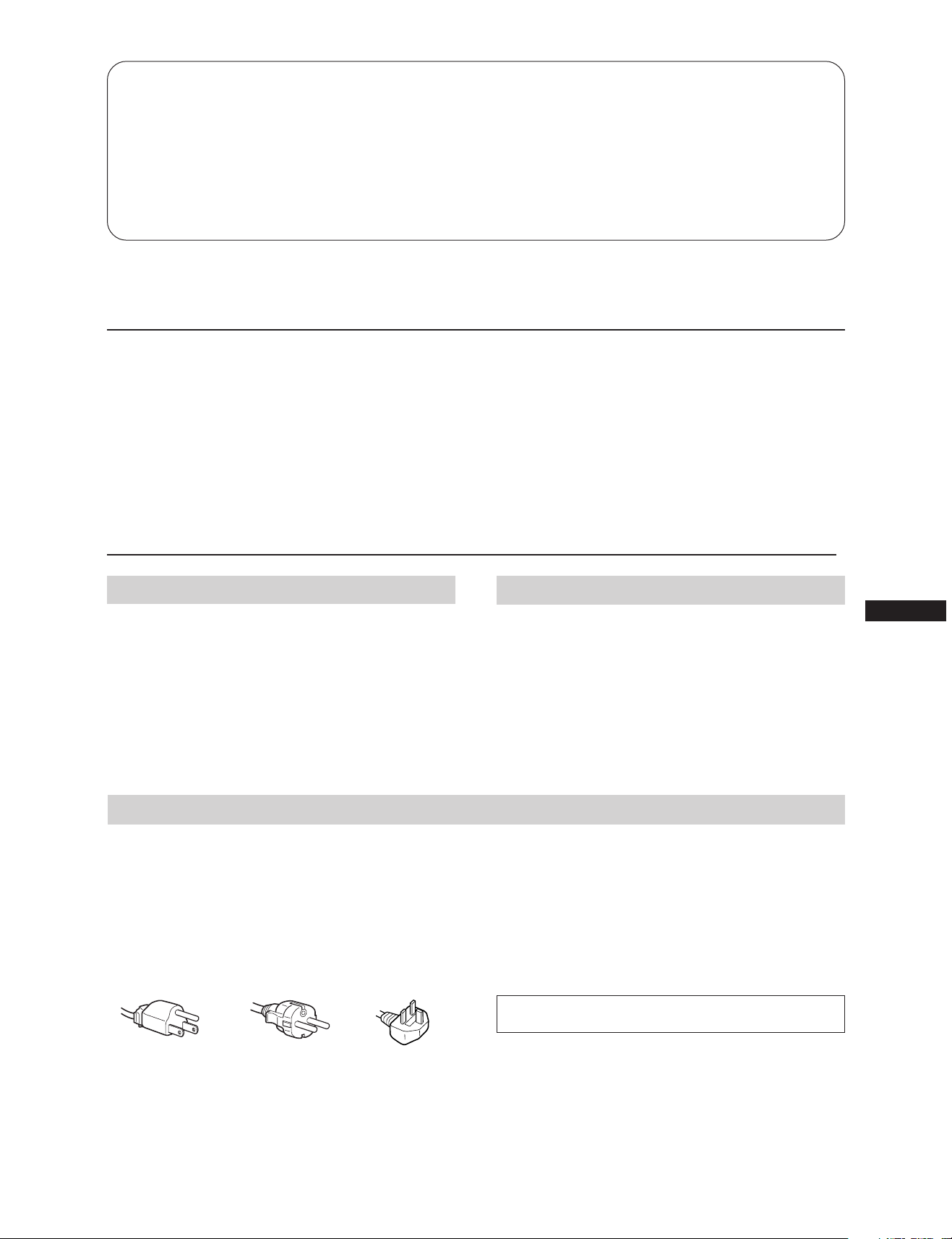
Table of Contents
Introduction ..............................................................................3
Precautions ...............................................................................3
Getting Started ......................................................................... 4
Using Your Monitor ................................................................ 4
Adjustments .............................................................................. 5
Entering New Timings ............................................................ 8
Introduction
Congratulations on your purchase of a Sony Multiscan SF
series monitor!
This monitor incorporates over 25 years of Sony experience
with Trinitron display technology, ensuring excellent
performance and outstanding reliability.
The advanced design of the SF series together with Digital
Multiscan Technology allows it to sync to any video mode
within its wide scan range. In addition, its three factory
Precautions
Power Saving Function ........................................................... 8
Plug and Play ........................................................................... 9
Use of the Tilt-Swivel .............................................................. 9
Damper Wire ............................................................................ 9
Specifications ............................................................................ 9
Troubleshooting ..................................................................... 10
preset color modes and three user adjustable color modes
give you unprecedented flexibility in matching on-screen
colors to hard copy print outs. Furthermore, this monitor
features digital controls with OSD (On Screen Display). It
delivers easier adjustment by visualizing your control
statement. All together, it delivers incredible performance
with the quality and support you can expect from Sony.
Installation
•Prevent internal heat build-up by allowing adequate air
circulation. Do not place the unit on surfaces (rugs,
blankets, etc.) nor near materials (curtains, draperies) that
may block the ventilation holes.
•Do not install the unit near heat sources such as radiators
or air ducts, nor in a place subject to direct sunlight,
excessive dust, mechanical vibration or shock.
•Do not place the unit near equipment which generates
magnetism, such as a converter or high voltage power
lines.
Warning on Power Connection
•Use a proper power cord for your local power supply.
For the customers in U.S.A.
If you do not do this, this monitor will not conform to
mandatory FCC standards.
For the customers in UK
If you use the monitor in UK, please use the supplied UK
cable with UK plug.
Examples of plug shape:
Maintenance
EN
•Clean the cabinet, panel and controls with a soft cloth
lightly moistened with a mild detergent solution. Do not
use any type of abrasive pad, alkaline cleaner, scouring
powder or solvent, such as alcohol or benzine.
•Do not rub, touch, or tap the surface of the screen with
sharp or abrasive items, like a ball point pen or a screw
driver. Otherwise, this type of contact may result in a
scratched picture tube.
•Before disconnecting the power cord, wait for at least 30
seconds after turning off the power switch to allow for the
discharging of static electricity on the CRT display surface.
•After the power has been turned on, the CRT is
demagnetized for approximately 5 seconds. This generates
a strong magnetic field around the bezel, which may affect
the data stored on magnetic tapes or disks near the bezel.
Place such magnetic recording equipment and tapes/disks
apart from this unit.
The socket-outlet should be installed near the equipment
and be easily accessible.
for 100 to 120 V AC
for 220 V to 240 V AC
for 240 V AC only
3
Page 4
Getting Started Using Your Monitor
This monitor will sync with any IBM or compatible system
equipped with VGA or greater graphics capability.
Although this monitor will sync to other platforms running
at horizontal frequencies between 30 and 85 kHz, including
Macintosh and Power Macintosh system, a cable adaptor is
required. Please consult your dealer for advice on which
adaptor is suitable for your needs.
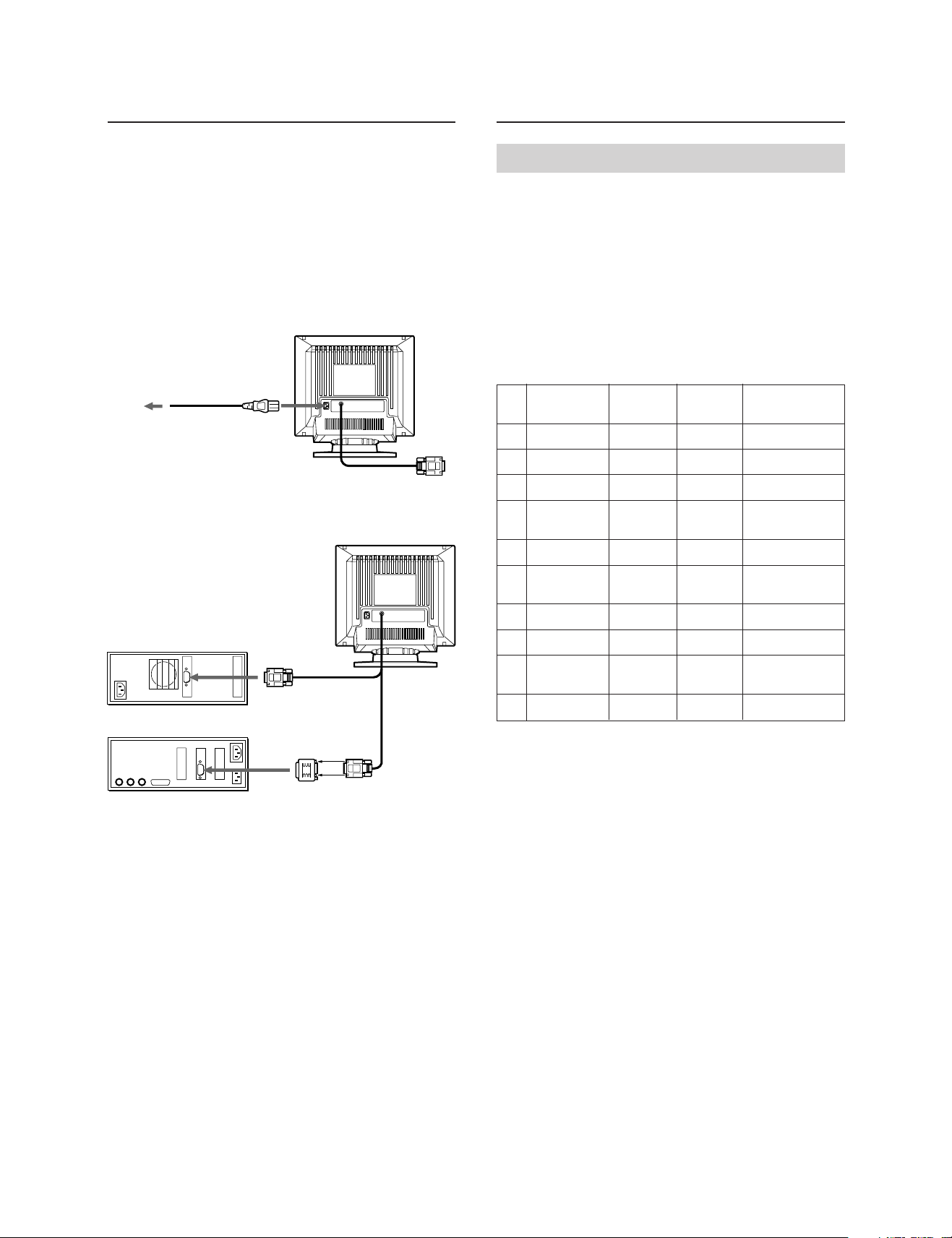
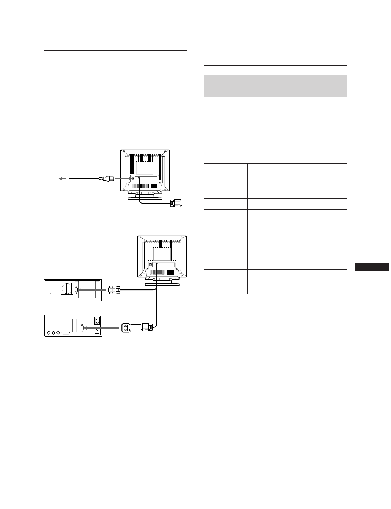
Step 1: With the monitor switched off, attach the power
cord to the monitor and the other end to a power
outlet.
Power cord (supplied)
to a power outlet
Step 2: With the computer switched off, attach the video
signal cable to the video output.
IBM or compatible computer
to video output
Apple computer
Macintosh Adapter
(supplied)
to video output
Preset and User Modes
The Multiscan 20sfII has factory preset modes for the 10
most popular industry standards for true “plug and play”
capability.
For less common modes, the Multiscan 20sfII’s Digital
Multiscan Technology will perform all of the complex
adjustments necessary to ensure a high quality picture for
any timing between 30 and 85␣ kHz.
However, due to the wide variety of video boards on the
market, it may be necessary for the user to fine tune the
vertical/horizontal size and centering.
Resolution
No.
(dots × lines)
640 × 480
1
720 × 400
2
640 × 480
3
832 × 624
4
800 × 600
5
1024 × 768
6
1280 × 1024
7
1024 × 768
8
1152 × 870
9
1280 × 1024
10
Note: For Windows
Horizontal
Frequency
31.5 kHz
31.5 kHz
43.3 kHz
49.7 kHz
53.7 kHz
60.0 kHz
64.0 kHz
68.7 kHz
68.7 kHz
80.0 kHz
® 4)
users, check your video board
Vertical
Frequency
60 Hz
70 Hz
85 Hz
75 Hz
85 Hz
75 Hz
60 Hz
85 Hz
75 Hz
75 Hz
manual or the utility program which comes with
your graphic board and select the highest available
refresh rate to maximize monitor performance.
Graphics Mode
VGA Graphic
VGA Text
VESA
1)
2)
Macintosh
16” Color
VESA
3)
2)
Macintosh
19” Color
VESA
VESA
3)
2)
2)
Macintosh
21” Color
VESA
3)
2)
1)
Step 3: Turn on the monitor and computer.
Step 4: If necessary, adjust the user controls according to
your personal preference.
The installation of your Multiscan 20sfII is complete. Enjoy
your monitor.
Note: Use HD15 (Female)-HD15 (Male without No.9 pin)
adaptor (supplied) for current DOS computer which
has no compliance of DDC 2AB and its No.9 pin is
disconverted.
4
Recommended horizontal timing conditions
Horizontal sync width should be: >4.8% of total horizontal
time.
Horizontal blanking width should be: >3.0 µsec.
1) VGA is a trademark of IBM Corporation.
2) VESA is a trademark of Video Electronics Standard
Association.
3) Macintosh is a trademark of Apple Computer Inc.
4) Windows
®
is a registered trademark of Microsoft.
Corporation in the United States and other countries.
Page 5
CENTER
CENTER
0 23
Adjustments
When one of the preset-type signals is input, no picture
adjustment is necessary.
You can, however, adjust the picture to your preferences by
the following procedure described below.
You can adjust the all items on the OSD (On Screen
Display). The item to be adjusted is indicated in white on
the OSD.
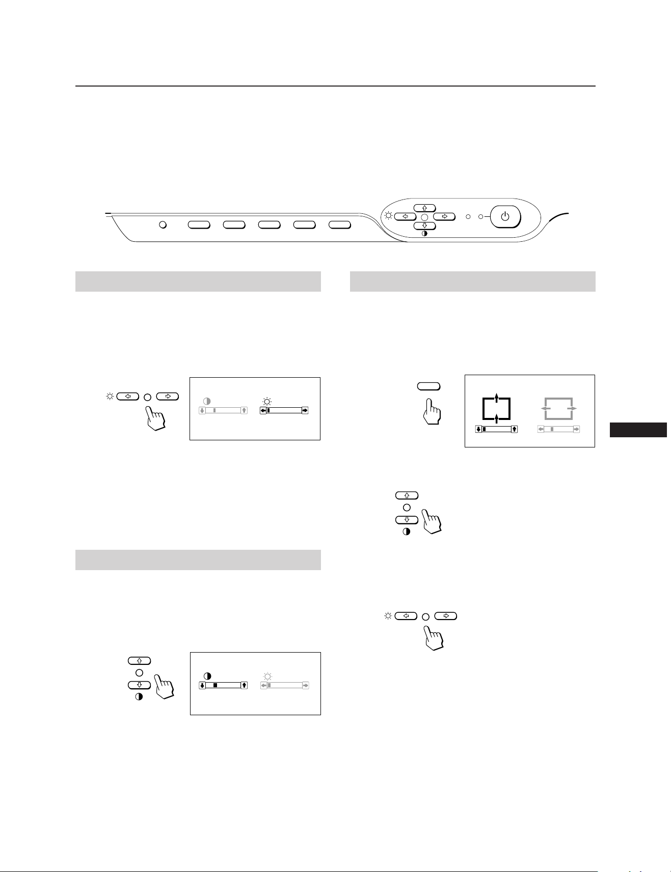
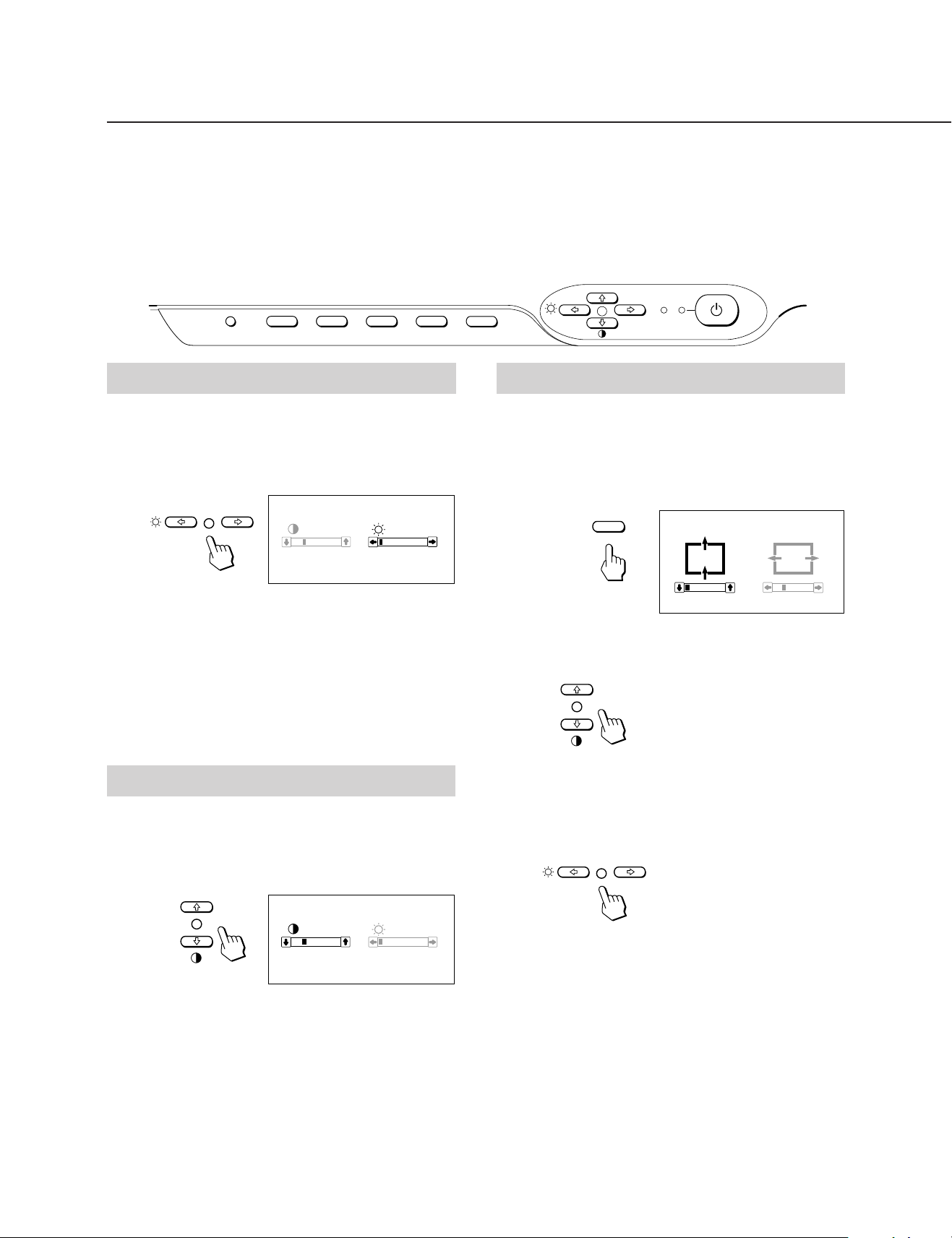
Control Panel
RESET
COLOR
CONV
GEOM
SIZE
Adjusting the Picture Brightness
The adjustment data becomes the common setting for all
input signal.
1 Press the ¨ ?// button.
The “CONTRAST/BRIGHTNESS” OSD (On Screen
Display) appears.
CONTRAST BRIGHTNESS
p Before adjusting the items, turn on the unit and feed the
video signal from the connected computer/work
station.
p Adjustments will be stored automatically.
POWER
CENTER
SAVING
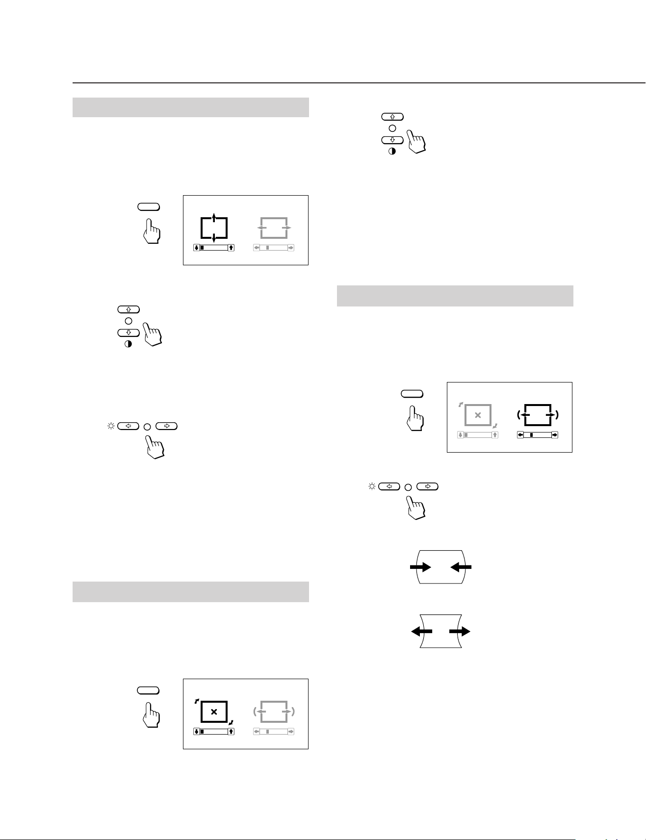
Adjusting the Picture Centering
The adjustment data becomes the unique setting for the
input signal received.
1 Press the CENTER button.
The “CENTER” OSD (On Screen Display) appears.
23
80.0
kHz/75Hz
0
2 Press the ¨ ?// buttons to adjust picture brightness.
? . . . for less brightness
/ . . . for more brightness
The “CONTRAST/BRIGHTNESS” OSD disappears 3
seconds after you release the buttons.
To reset, press RESET button while the OSD is on.
Adjusting the Picture Contrast
The adjustment data becomes the common setting for all
input signal.
1 Press the > >/. button.
The “CONTRAST/BRIGHTNESS” OSD (On Screen
Display) appears.
CONTRAST BRIGHTNESS
23
80.0
kHz/75Hz
2 Press the > >/. buttons to adjust picture contrast.
> . . . for more contrast
. . . . for less contrast
The “CONTRAST/BRIGHTNESS” OSD disappears 3
seconds after you release the buttons.
0
EN
2 For vertical picture adjustment
Press the > >/. buttons.
> . . . to move up
. . . . to move down
For horizontal picture adjustment
Press the ¨ ?// buttons.
? . . . to move left
/ . . . to move right
To erase the “CENTER” OSD, press the CENTER button
again.
The “CENTER” OSD automatically disappears 10 seconds
after you release the buttons.
To reset, press RESET button while the OSD is on.
To reset, press RESET button while the OSD is on.
5
Page 6
Adjustments
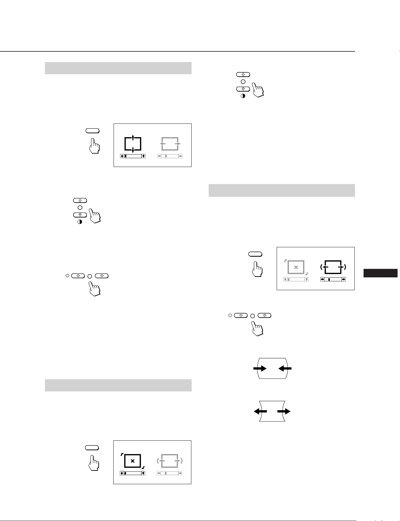
Adjusting the Picture Size
The adjustment data becomes the unique setting for the
input signal received.
1 Press the SIZE button.
The “SIZE” OSD (On Screen Display) appears.
SIZE
SIZE
0 23
2 For vertical picture adjustment
Press the > >/. buttons.
> . . . to enlarge
. . . . to diminish
For horizontal picture adjustment
Press the ¨ ?// buttons.
2 Press the > >/. buttons.
> . . .to rotate clockwise
. . . . to rotate counterclockwise
To erase the “GEOMETRY” OSD, press the GEOM button
again.
The “GEOMETRY” OSD automatically disappears 10
seconds after you release the buttons.
To reset, press RESET button while the OSD is on.
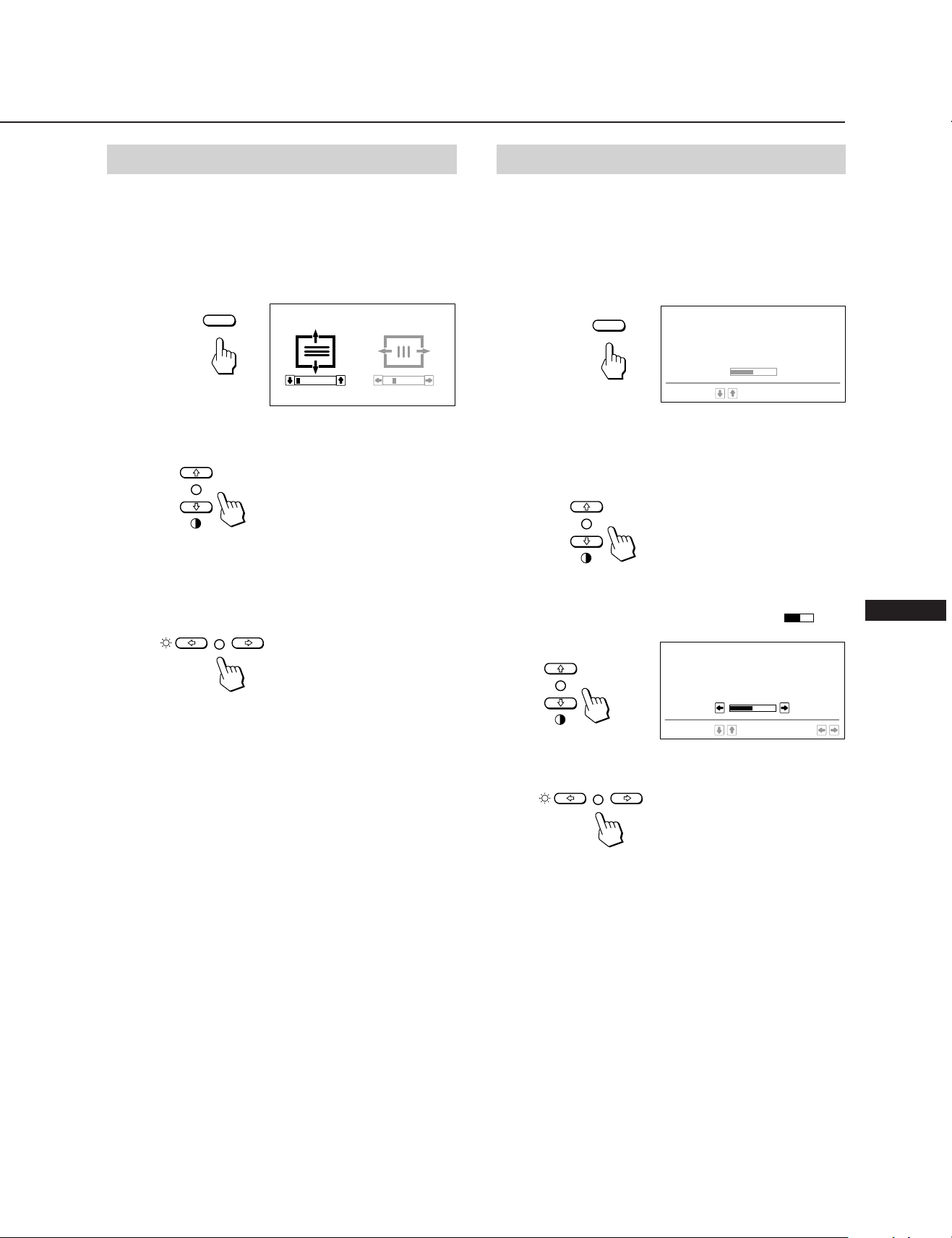
Adjusting the Pincushion
The adjustment data becomes the unique setting for the
input signal received.
1 Press the GEOM button.
The “GEOMETRY” OSD (On Screen Display) appears.
GEOMETRY
GEOM
? . . . to diminish
/ . . . to enlarge
To erase the “SIZE” OSD, press the SIZE button again.
The “SIZE” OSD automatically disappears 10 seconds after
you release the buttons.
To reset, press RESET button while the OSD is on.
Adjusting the Picture Rotation
The adjustment data becomes the common setting for all
input signal.
1 Press the GEOM button.
The “GEOMETRY” OSD (On Screen Display) appears.
GEOMETRY
GEOM
0 23
2 Press the ¨ ?// buttons.
? . . . to diminish the picture sides
/ . . . to expand the picture sides
To erase the “GEOMETRY” OSD, press the GEOM button
again.
The “GEOMETRY” OSD automatically disappears 10
seconds after you release the buttons.
To reset, press RESET button while the OSD is on.
6
0 23
Page 7
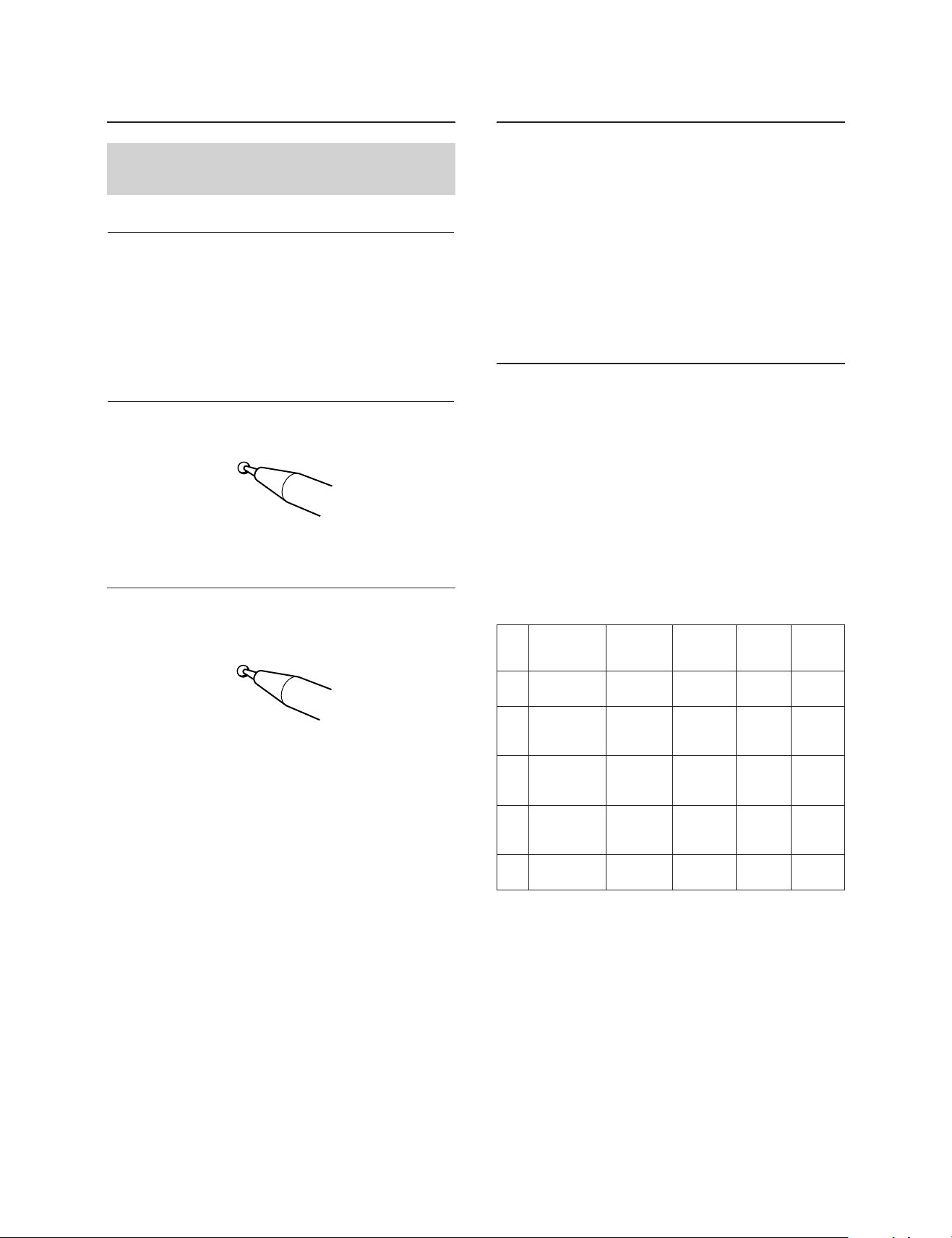
COLOR TEMPERATURE
9300K
6500K
5000K
SELECT
50
SET
Adjusting the Convergence
Setteing the Color Temperature
The adjustment data becomes the common setting for all
input signals.
1 Press the CONV button.
The “CONVERGENCE” OSD (On Screen Display)
appears.
CONVERGENCE
CONV
0 23
2 For vertical adjustment
Press the > >/. buttons.
> . . . to move Red up and Blue down
. . . . to move Red down and Blue up
For horizontal adjustment
Press the ¨ ?// buttons.
The selected color temperature becomes the common setting
for all input signals. (The factory presetting is 9300K.)
1 Press COLOR button.
The “COLOR TEMPERATURE” OSD (On Screen
Display) appears.
COLOR TEMPERATURE
COLOR
SELECT
9300K
6500K
5000K
50
2 Adjust with the > >/. and ¨ ?// buttons.
To select 9300K, 6500K, or 5000K
Press > >/. buttons.
To obtain the desired color temperature between
5000K and 9300K
1 Press > >/. buttons to select user mode (
).
EN
? . . . to move Red to the right and Blue to the left
/ . . . to move Red to the left and Blue to the right
To erase the “CONVERGENCE” OSD, press the CONV
button again.
The “CONVERGENCE” OSD automatically disappears
10 seconds after you release the buttons.
To reset, press RESET button while the OSD is on.
2 Press ¨ ?// buttons.
? . . . for lower temperature (to be reddish)
/ . . . for higher temperature (to be blueish)
Your most recent adjusted color temperature will be
recalled by pressing > >/. button.
The factory presetting is 6500K for the user adjustable
mode of color temperature.
To erase the “COLOR TEMPERATURE” OSD, press the
COLOR button again.
The “COLOR TEMPERATURE” OSD automatically
disappears 10 seconds after you release the buttons.
To reset, press RESET button while the OSD is on.
7
Page 8
Adjustments
Entering New Timings
Resetting the Adjustment
Data to Factory-preset Levels
To reset an adjustment item
Press the button of the adjustment item you want to reset,
and then press the RESET button before the OSD (On
Screen Display) disappears.
To reset the brightness, contrast, size,
center, pincushion, and color
temperature adjustment data at once (for
the received signal)
Press the RESET button with something like a pen for 1
second when no OSD is shown.
RESET
To reset all adjustment data to factorypreset levels
Press and hold the RESET button for more than 2 seconds.
All adjustment data including the brightness and contrast
are reset to factory-preset levels.
RESET
When using a video mode that is not one of the 10 factory
preset modes, some fine tuning may be required to optimize
the display to your preferences. Simply adjust the monitor
according to the preceding adjustment instructions. The
adjustments will be stored automatically and recalled
whenever that mode is used.
A total of 15 user-defined modes can be stored in memory.
If the 16th mode is entered, it will replace the first.
Power Saving Function
This monitor meets the power saving guidelines set by the
EPA Energy Star Program as well as the more stringent
TCO95 (NUTEK) guidelines. It is capable of reduced power
consumption when used with a computer equipped with
Display Power Management Signaling (DPMS). By sensing
the absence of the sync signal coming from the computer, it
will reduce the power consumption as follows:
CAUTION: The Power Saving function will automatically
put the monitor into Active-off state if the power
switch is turned on without any video signal
input. Once the horizontal and vertical syncs are
sensed, the monitor will automatically return to
its Normal operation state.
POWER
SAVING
indicator
off
orange on
orange on
orange on
u Power
indicator
green on
green on
green on
off
Mode
1
2
power saving)
3
power saving)
4
power saving)
State
Normal
operation
Standby
(1st step of
Suspend
(2nd step of
Active-off
(3rd step of
Power
consumption
100%
approx.
70%
approx.
10%
approx.
4%
Required
resumption
time
—
approx.
3 sec.
approx.
3 sec.
approx.
10 sec.
8
5
Power-off
0%
—
off
off
Page 9
Plug and Play
Specifications
This monitor complies with the DDC1, DDC2B and
DDC2AB which are the Display Data Channel (DDC)
standards of VESA.
When a DDC1 host system is connected, the monitor
synchronizes with the V. CLK in accordance with the VESA
standards and outputs the EDID (Extended Display
Identification) to the data line.
When a DDC2B or DDC2AB host system is connected, the
monitor automatically switches to each communication.
DDC is a trademark of Video Electronics Standard Association.
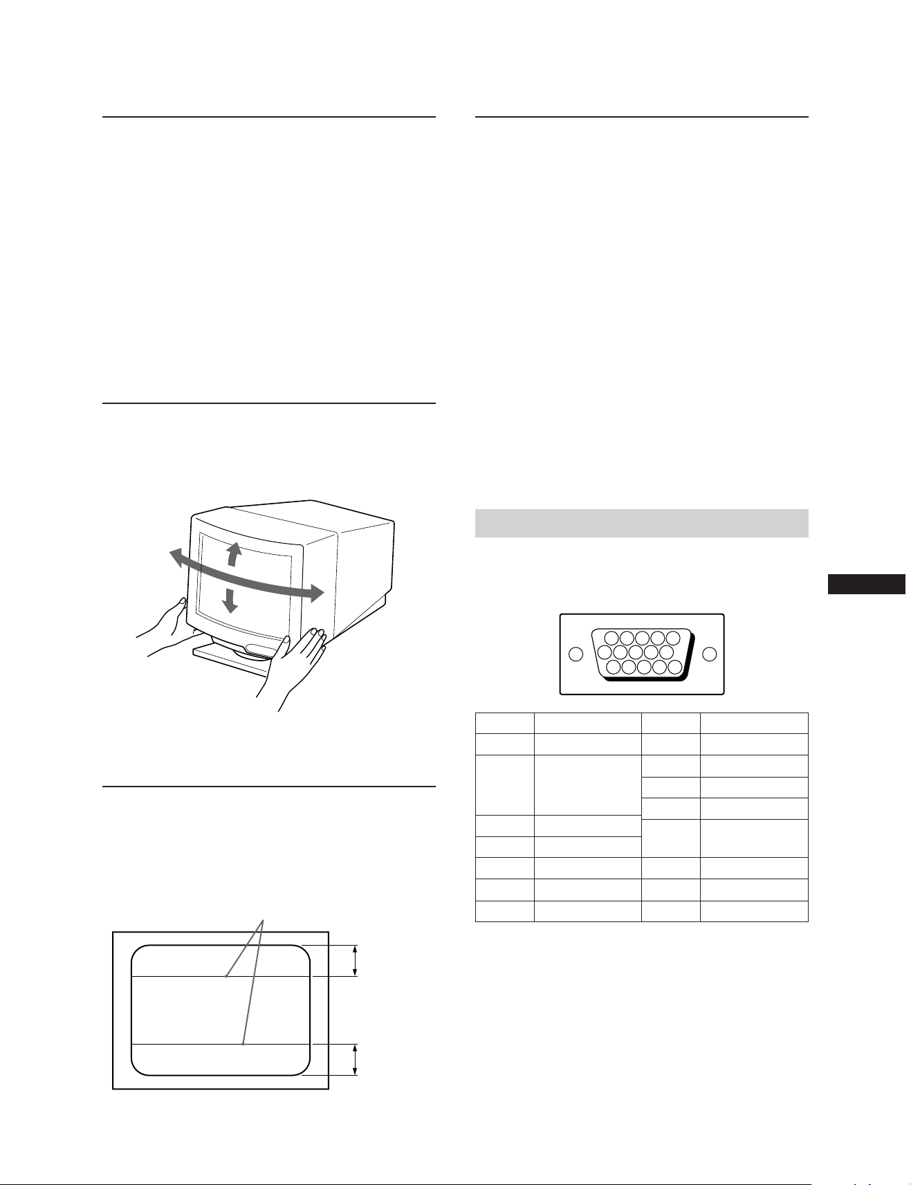
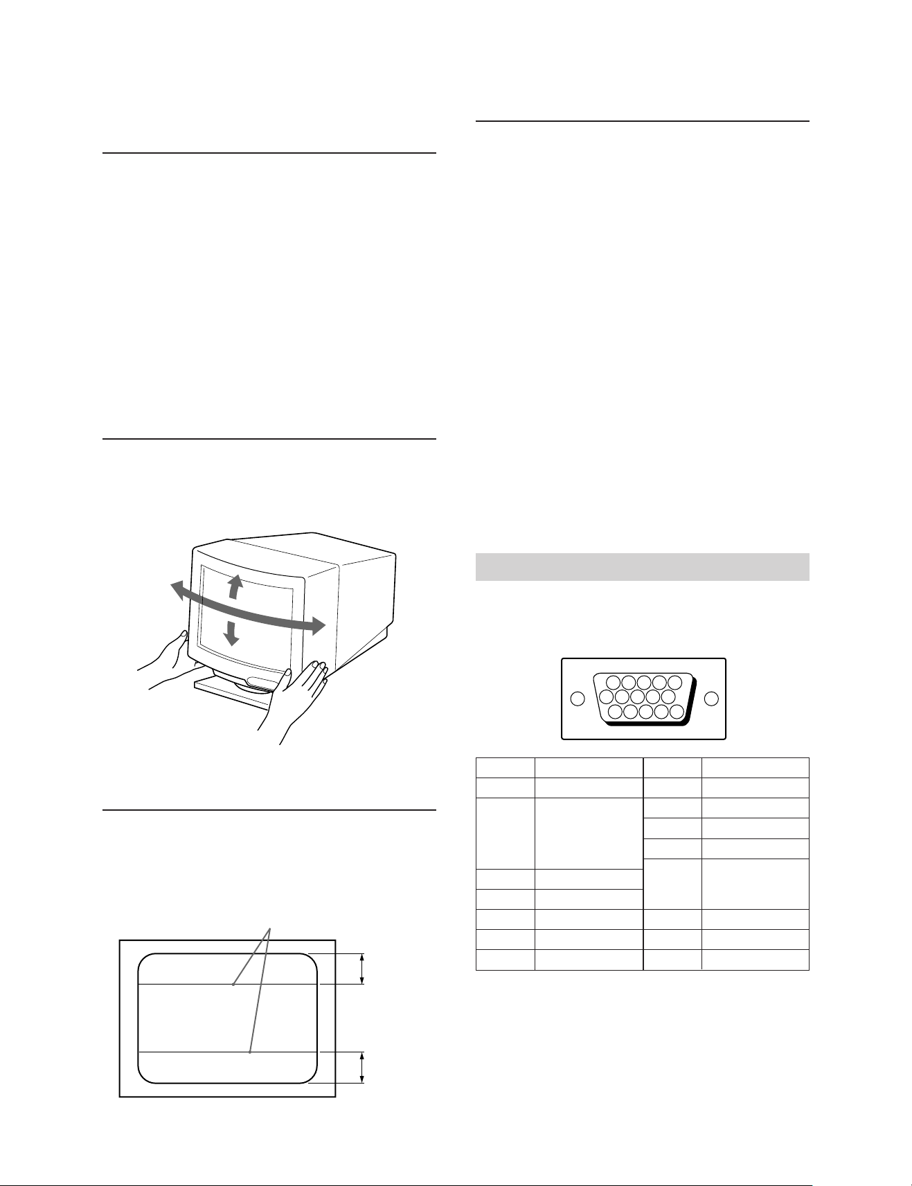
Use of the Tilt-Swivel
With the tilt-swivel, this unit can be adjusted to be viewed at
your desired angle within 90˚ horizontally and 20˚ vertically.
To turn the unit vertically and horizontally, hold it at its
bottom with both hands.
15°
45°
45°
Picture tube 0.30 mm aperture grille pitch
20␣ inches measured diagonally
90-degree deflection
Viewable image size Approx. 388 × 292 mm (w/h)
3
(15
19.1” viewing image
Resolution Horizontal: Max. 1280 dots
Vertical: Max. 1024 lines
Standard image area Approx. 373 × 280 mm (w/h)
3
(14
or
Approx. 350 × 280 mm (w/h)
7
(13
Deflection frequency Horizontal: 30 to 85 kHz
Vertical: 48 to 150 Hz
AC input voltage/current
100 to 120 V, 50/60 Hz, 1.7 A
220 to 240 V, 50 – 60 Hz, 1.2 A
Power consumption Max. 150 W
Dimensions Approx. 472 × 493.5 × 501 mm (w/h/d)
Mass Approx. 29.5 kg (65 lb 1 oz)
(18
5
1
/8
× 11
/2 inches)
1
/4 × 11
/8 × 11
/8 × 19 1/2 × 19
/8 inches)
1
/8 inches)
3
/4 inches)
Pin assignment
Video signal cable (HD15) (Male)
The cable accepts RGB video signals (0.714 Vp-p, positive),
and SYNC signals.
EN
5°
Damper Wire
Using a white background, very thin horizontal stripes on
the screen are visible as shown on the illustration. These
stripes are damper wires. These wires are attached to the
aperture grille inside the Trinitron tube and are there to
damp vibrations of the aperture grille in order to prevent
them from influencing to the picture quality.
Damper wire
Approx. 8 cm
876
5432
109
1514131211
Pin No.
8
9
10
11
12
13
14
15
Signal
Blue Ground
DDC + 5V*
Ground
—
Bi-Directional
Data (SDA)*
H. Sync
V. Sync
Data Clock (SCL)*
1
Pin No.
1
2
3
4
5
6
7
* Display Data Channel (DDC) Standard by VESA.
Design and specifications are subject to change without
notice.
Signal
Red
Green
(Composite
Sync on Green)
Blue
—
DDC Ground*
Red Ground
Green Ground
Approx. 8 cm
9
Page 10

Troubleshooting
This section may help you isolate a problem and as a result,
eliminate the need to contact technical support, allowing
continued productivity.
No picture
/ If neither the u (power) indicator nor the
POWER SAVING indicator is lit
— Check that the power cord is properly
connected.
— Check that the power switch is in the “ON”
position.
/ If the POWER SAVING indicator is lit
— Check that your computer power switch is
in the “ON” position.
— The monitor will recover when you press
any key on the keyboard of the computer.
— Check that the video cable is properly
connected.
— Ensure that no pins are bent or pushed in
the HD15 connector of the cable.
— Check that the video card is seated
completely in a proper bus slot.
— Check that the video sync signal is within
that specified for the monitor.
— If using a Mac system, check that a proper
HD15-D15 adaptor is provided to work
correctly with your Macintosh.
/ If you do the above procedures and the
monitor does not recover.
— Unplug the video cable (HD15) then press
and hold the ¨ + button for 2 seconds to
display the color bars. Then, turn the
monitor off and on by pressing the
u power switch.
If the monitor does not recover, the
monitor is out of order.
/ If the u (power) and/or the POWER SAVING
indicator is flashing
— Turn the monitor off and on. If the
indicator is not flashing, the monitor is in
the normal condition. If the indicator is still
flashing, there is a potential monitor
failure.
/ If your computer is a Macintosh system
— Check that micro switches are properly set
on the Macintosh adapter for your system.
(See the adapter manual.)
Picture is scrambled
/ Check your graphics board manual for the
proper monitor setting on your Multiscan
20sfII.
/ Check this manual and confirm that the
graphic mode and the frequency at which you
are trying to operate is supported. Even
within the proper range some video boards
may have a sync pulse that is too narrow for
the monitor to sync correctly.
Color is not uniform
/ Trip the power switch once to activate the
Auto-degauss cycle*.
White does not look white
/ Adjust the “COLOR TEMPERATURE” on the
OSD. (page 7)
/ If your computer is a Macintosh system, check
that micro switches are properly set on the
Macintosh adapter for your system. (See the
adapter manual.)
Screen image is not centered or sized properly
/ Adjust the “CENTER”, “SIZE”, or
“GEOMETRY” on the OSD (page 5, 6).
/ Some video modes do not fill the screen to the
edge of the monitor. There is no single answer
to solve the problem. There is a tendency to
have this problem on higher refresh timings
and Macintosh video timings.
Edges of the image are curved
/ Adjust pincushion using the “GEOMETRY”
OSD. (page 6)
White lines show red or blue shades at edges
/ Adjust the “CONVERGENCE” on the OSD.
(page 7)
Picture is fuzzy
/ Adjust the “CONTRAST” and
“BRIGHTNESS” on the OSD (page 5). We
have come across several brands of SVGA
boards that have an excessive video output
level which creates a fuzzy picture at max
contrast.
/ Trip the power switch once to activate the
Auto-degauss cycle*.
/ If red or blue shades are found at the edge of
images, adjust the “CONVERGENCE” on the
OSD. (page 7)
Picture bounces or has wavy oscillations
/ Isolate and eliminate any potential sources of
electric or magnetic fields. Common causes for
this symptom are electric fans, fluorescent
lighting, laser printers, and so on.
/ If you have another monitor close to this
monitor, increase the distance between them
to reduce the interference.
/ Try plugging the monitor into a different AC
outlet, preferably on a different circuit.
/ Try the monitor on a completely different
computer in a differnt room.
Picture appears to be ghosting
/ Eliminate the use of video cable extension
cables and/or video switch boxes if this
symptom occurs. Excessive cable length or
weak connections can produce this symptom.
Two fine horizontal lines (wires) are visible
/ These wires stabilize the vertically striped
Aperture Grille. This Aperture Grille allows
more light to pass through to the screen giving
the Trinitron CRT more color and brightness.
10
Page 11

Wavy or elliptical (moire) pattern is visible
/ Due to the relationship between resolution,
monitor dot pitch and the pitch of some image
patterns, certain screen backgrounds,
especially gray, sometimes show moire. This
can only be eliminated by changing your
desktop pattern.
*The Auto-degauss function demagnetizes the metal
frame of the CRT to obtain a neutral field for uniform
color reproduction. If a second degauss cycle is needed,
allow a minimum interval of 20 minutes for the best
result.
•If the problem persists, call your authorized Sony dealer
from a location near your monitor.
•Note the model name and the serial number of your
monitor. Also note the make and name of your computer
and video board.
EN
11
Page 12

Table des matières
Introduction ............................................................................12
Précautions .............................................................................12
Préparation .............................................................................13
Utilisation de votre moniteur ..............................................13
Réglages...................................................................................14
Introduction de nouvelles synchronisations.....................17
Introduction
Nous vous félicitons d’avoir fait l’acquisition d’un moniteur
Multiscan SF Sony !
Ce moniteur intègre plus de 25 années d’expérience de Sony
en matière de technologie d’affichage Trinitron, qui vous
garantit d’excellentes performances et une fiabilité
exceptionnelle.
La conception avancée des moniteurs SF et la technologie
Multiscan numérique lui permettent de se synchroniser sur
n’importe quel mode vidéo dans sa vaste plage de balayage.
Précautions
Economie d’énergie ............................................................... 17
Un moniteur prêt à l’emploi ................................................ 18
Utilisation du support pivotant .......................................... 18
Fil d’amortissement............................................................... 18
Spécifications .......................................................................... 18
Dépannage .............................................................................. 19
De plus, avec trois modes de couleur par défaut et trois
modes de couleur réglables par l’utilisateur, il assure une
flexibilité inégalée en matière de correspondance des
couleurs d’affichage et d’impression. Ce moniteur est par
ailleurs doté de commandes numériques et du système OSD
(menus d’affichage). Il se règle d’une façon très simple en
visualisant vos réglages. Bref, il allie des performances
exceptionnelles à la qualité et à la fiabilité que vous êtes en
droit d’attendre d’un Sony.
Installation
•Veillez à assurer une circulation d’air adéquate pour éviter
une surchauffe interne de l’appareil. Ne placez pas
l’appareil sur des surfaces textiles (tapis, couvertures, etc.)
ni à proximité de rideaux ou de draperies susceptibles
d’obstruer les orifices de ventilation.
•N’installez pas l’appareil à proximité de sources de
chaleur telles qu’un radiateur ou une conduite d’air chaud,
ni dans un endroit exposé à la lumière directe du soleil, à
des poussières excessives, à des vibrations ou à des chocs
mécaniques.
•N’installez pas l’appareil à proximité d’un équipement qui
génère un champ magnétique, comme un convertisseur ou
des lignes à haute tension.
Entretien
•Nettoyez le châssis, le panneau de verre et les commandes
à l’aide d’un chiffon doux légèrement imprégné d’une
solution détergente douce. N’utilisez jamais de tampons
abrasifs, d’ammoniaque, de poudre à récurer ni de
solvants tels que l’alcool ou le benzène.
•Ne frottez pas, ne touchez pas et ne tapotez pas la surface
de l’écran avec des objets abrasif ou aux arêtes vives
comme un stylo à bille ou un tournevis. Ce type de contact
risque en effet de rayer le tube image.
Avertissement: raccordement électrique
•Utilisez un cordon d’alimentation approprié à votre
secteur.
Pour les clients aux Etats-Unis
Si vous ne le faites pas, ce moniteur ne sera pas conforme
aux normes FCC en vigueur.
Pour les clients au Royaume-Uni
Si vous utilisez ce moniteur au Royaume-Uni, utilisez le
cordon et la fiche pour le Royaume-Uni, utilisez le cordon
et la fiche pour le Royaume-Uni fournis.
Exemples de formes de fiche
•Avant de débrancher le cordon d’alimentation, attendez a
moins 30 secondes après avoir actionné l’interrupteur
d’alimentation de manière à permettre la décharge de
l’électricité statique sur la surface de l’écran CRT.
•Après que le courant a été branché, le CRT est démagnétisé
pendant environ 5 secondes. Cela génère un puissant
champ magnétique autour de l’encadrement qui peut
affecter les données mémorisées sur une bande magnétique
ou des disquettes situées à proximité. Placez ces systèmes
d’enregistrement magnétique et ces bandes/ disquettes à
l’écart de cet appareil.
pour CA 100 à 120 V pour CA 240 V
pour CA 220 à 240 V
uniquement
12
La prise murale doit être installée à proximité de
l’équipement et être aisément accessible.
Page 13
Préparation
Ce moniteur se synchronise sur n’importe quel système
IBM ou compatible équipé d’une carte VGA ou de capacités
graphiques supérieures. Bien que ce moniteur se
synchronise à d’autres plate-forme fonctionnant sur des
fréquences horizontales comprises entre 30 et 85 kHz, y
compris Macintosh et Power Macintosh, un adaptateur de
câble est requis. Veuillez consulter votre distributeur pour
des conseils relatifs à l’adaptateur répondant à vos besoins.
1re étape: Le moniteur étant hors tension, raccordez le
cordon d’alimentation au moniteur et l’autre
extrémité à la prise de courant.
Utilisation de votre
moniteur
Modes par défaut et
utilisateur
Le Multiscan 20sfII comporte des modes par défaut pour les
10 normes industrielles les plus courantes qui le rendent
véritablement “prêt à l’emploi”.
Pour les modes moins courants, la technologie numérique
Multiscan du Multiscan 20sfII réalise tous les réglages
complexes nécessaires pour assurer une haute qualité
d’image pour n’importe quelle synchronisation entre 30 et
85 kHz.
cordon d’alimentation (fourni)
à la prise de courant
2e étape: L’ordinateur étant hors tension, branchez le
câble de signal vidéo à la sortie vidéo.
ordinateur IBM ou compatible
vers la sortie vidéo
ordinateur Apple
Adaptateur
Macintosh (fourni)
vers la sortie vidéo
Résolution
N°
(points × lignes)
640 × 480
1
720 × 400
2
640 × 480
3
832 × 624
4
800 × 600
5
1024 × 768
6
1280 × 1024
7
1024 × 768
8
1152 × 870
9
1280 × 1024
10
Remarque: Les utilisateurs Windows
Fréquence
horizontale
31.5 kHz
31.5 kHz
43.3 kHz
49.7 kHz
53.7 kHz
60.0 kHz
64.0 kHz
68.7 kHz
68.7 kHz
80.0 kHz
le manuel de leur carte vidéo ou le programme
utilitaire fourni avec la carte graphique et
sélectionner le taux de régénération le plus
élevé de manière à maximiser les performances
du moniteur.
Fréquence
verticale
60 Hz
70 Hz
85 Hz
75 Hz
85 Hz
75 Hz
60 Hz
85 Hz
75 Hz
75 Hz
Mode graphique
VGA Graphic
VGA Text
2)
VESA
Macintosh
16” Color
2)
VESA
Macintosh
19” Color
2)
VESA
2)
VESA
Macintosh
21" Color
2)
VESA
4)
doivent contrôler
1)
1)
3)
3)
F
3)
3e étape: Mettez le moniteur et l’ordinateur sous tension.
4e étape: Si nécessaire, réglez les commandes utilisateur
selon vos préférences personnelles.
L’installation de votre Multiscan 20sfII est terminée. Nous
vous souhaitons beaucoup de plaisir avec votre moniteur.
Remarque: Utilisez un adaptateur HD15 (femelle) - HD15
(mâle sans broche N°9) (fourni) pour
l'ordinateur DOS actuel qui n'est pas conforme
aux spécifications DDC 2AB et dont la broche
N°9 est déconnectée.
Conditions de synchronisation horizontale préconisées
Largeur de synchronisation horizontale : 4,8% de la durée
horizontale totale.
Largeur de neutralisation horizontale :␣ > 3,0 µs
1) VGA est une marque déposée de IBM Corporation.
2) VESA est une marque déposée de Vidéo Electronics
Standard Association.
3) Macintosh est une marque déposée de Apple Computer
Inc.
4) Windows
Corporation aux Etats-Unis d’Amérique et/ou dans
d’autres pays.
®
est une marque déposée de Microsoft
13
Page 14
CENTER
CENTER
0 23
Réglages
Si l’un des signaux présélectionnés est transmis, aucun
réglage n’est requis.
Vous pouvez cependant régler l’image en fonction de vos
préférences en appliquant la procédure décrite ci-dessous.
Vous pouvez régler tous les paramètres à l’aide des menus
d’affichage OSD. Le paramètre en cours de réglage est
affiché en blanc dans le menu.
Panneau de commande
RESET
COLOR
CONV
GEOM
SIZE
CENTER
Réglage de la luminosité de l’image
La valeur introduite devient le réglage commun à tous les
signaux d’entrée.
1 Appuyez sur la touche ¨ ?//.
Le menu “CONTRAST/BRIGHTNESS” apparaît.
CONTRAST BRIGHTNESS
23
80.0
kHz/75Hz
0
p Avant d’ajuster les différents paramètres, mettez
l’appareil sous tension et transmettez le signal vidéo de
l’ordinateur/poste de travail connecté.
p Les réglages sont mémorisés automatiquement.
POWER
SAVING
Réglage du centrage de l’image
La valeur introduite devient le réglage unique pour tous les
signaux d’entrée.
1 Appuyez sur la touche CENTER.
Le menu “CENTER” apparaît.
2 Appuyez sur les touches ¨ ?// pour régler la
luminosité de l’image.
? . . . pour moins de luminosité
/ . . . pour plus de luminosité
Le menu “CONTRAST/BRIGHTNESS” disparaît 3 secondes
après que vous avez relâché les touches.
Pour réinitialiser le réglage, appuyez sur la touche RESET
pendant que le menu est affiché.
Réglage du contraste de l’image
La valeur introduite devient le réglage commun à tous les
signaux d’entrée.
1 Appuyez sur la touche >> /..
Le menu “CONTRAST/BRIGHTNESS” apparaît.
CONTRAST BRIGHTNESS
23
80.0
kHz/75Hz
2 Appuyez sur les touches >> /. pour régler la
luminosité de l’image.
> . . . pour plus de contraste
. . . . pour moins de contraste
Le menu “CONTRAST/BRIGHTNESS” disparaît 3 secondes
après que vous avez relâché les touches.
0
2 Pour le réglage du centrage vertical.
Appuyez sur les touches > >/..
> . . . pour remonter l’image
. . . . pour abaisser l’image
Pour le réglage du centrage horizontal.
Appuyez sur les touches ¨ ?//.
? . . . pour déplacer l’image vers la gauche
/ . . . pour déplacer l’image vers la droite
Pour désactiver le menu “CENTER”, appuyez à nouveau
sur la touche CENTER.
Le menu “CENTER” disparaît automatiquement 10
secondes après que vous avez relâché les touches.
Pour réinitialiser le réglage, appuyez sur la touche RESET
pendant que le menu est affiché.
Pour réinitialiser le réglage, appuyez sur la touche RESET
pendant que le menu est affiché.
14
Page 15
Réglage de la taille de l’image
La valeur introduite devient le réglage unique pour tous les
signaux d’entrée.
1 Appuyez sur la touche SIZE
Le menu “SIZE” apparaît.
SIZE
SIZE
0 23
2 Pour le réglage de la taille verticale
Appuyez sur les touches > >/..
> . . . pour agrandir l’image
. . . . pour réduire la taille de l’image
Pour le réglage de la taille horizontale
Appuyez sur les touches ¨ ?//.
2 Appuyez sur les touches > >/. pour tourner l’image
>
. . . dans le sens des aiguilles d’une montre
. . . .
dans le sens contraire des aiguilles d’une
montre
Pour désactiver le menu “GEOMETRY”, appuyez à
nouveau sur la touche GEOM.
Le menu “GEOMETRY” disparaît 10 secondes après que
vous avez relâché les touches.
Pour réinitialiser le réglage, appuyez sur la touche RESET
pendant que le menu est affiché.
Réglage de la distorsion en coussin
La valeur introduite devient le réglage unique pour tous les
signaux d’entrée.
1 Appuyez sur la touche GEOM.
Le menu “GEOMETRY” apparaît.
GEOMETRY
GEOM
? . . . pour réduire la taille de l’image
/ . . . pour agrandir l’image
Pour désactiver le menu “SIZE”, appuyez à nouveau sur la
touche SIZE.
Le menu “SIZE” disparaît automatiquement 10 secondes
après que vous avez relâché les touches.
Pour réinitialiser le réglage, appuyez sur la touche RESET
pendant que le menu est affiché.
Réglage de la rotation de l’image
La valeur introduite devient le réglage commun à tous les
signaux d’entrée.
1 Appuyez sur la touche GEOM.
Le menu “GEOMETRY” apparaît.
GEOMETRY
GEOM
F
0 23
2 Appuyez sur les touches ¨ ?// pour tourner l’image
? . . . pour élargir les côtés de l’image
/ . . . pour comprimer les côtés de l’image
Pour désactiver le menu “GEOMETRY”, appuyez à
nouveau sur la touche GEOM.
Le menu “GEOMETRY” disparaît 10 secondes après que
vous avez relâché les touches.
0 23
Pour réinitialiser le réglage, appuyez sur la touche RESET
pendant que le menu est affiché.
15
Page 16

COLOR TEMPERATURE
9300K
6500K
5000K
SELECT
50
SET
Réglages
Réglage de la convergence
La valeur introduite devient le réglage commun à tous les
signaux d’entrée.
1 Appuyez sur la touche CONV.
Le menu “CONVERGENCE” apparaît.
CONVERGENCE
CONV
0 23
2 Pour le réglage de la convergence verticale
Appuyez sur les touches > >/..
> . . . pour décaler le rouge vers le haut et le bleu
vers le bas
. . . . pour décaler le rouge vers le bas et le bleu vers
le haut
Réglage de la température
des couleurs
La température de couleur sélectionnée devient le réglage
commun à tous les signaux d’entrée. (Le réglage en usine est
9300K)
1 Appuyez sur la touche COLOR.
Le menu “COLOR TEMPERATURE” apparaît.
COLOR TEMPERATURE
COLOR
SELECT
2 Sélectionnez la valeur de réglage à l’aide des touches
> >/. et ¨ ?//.
Pour sélectionner une température de 9300K, 6500K
ou 5000K
Appuyez sur les touches > >/..
La température de couleur sélectionnée est indiquée en
jaune.
9300K
6500K
5000K
50
Pour le réglage de la convergence horizontale
Appuyez sur les touches ¨ ?//.
? . . . pour décaler le rouge vers la droite et le bleu
vers la gauche
/ . . . pour décaler le rouge vers la gauche et le bleu
vers la droite
Pour désactiver le menu “CONVERGENCE”, appuyez à
nouveau sur la touche CONV.
Le menu “CONVERGENCE” disparaît automatiquement 10
secondes après que vous avez relâché les touches.
Pour réinitialiser le réglage, appuyez sur la touche RESET
pendant que le menu est affiché.
16
Pour obtenir la température de couleur voulue entre
5000K et 9300K
1 Appuyez sur les touches > >/. pour sélectionner
la valeur de réglage (
2 Appuyez sur les touches ¨ ?//.
? . . . pour diminuer la température (pour être
rougeâtre)
/ . . . pour augmenter la température (pour être
bleuâtre)
La température de couleur sélectionnée en dernier lieu
peut être restaurée en appuyant sur les touches > >/..
Le réglage par défaut de la température de couleur
réglable par l’utilisateur est de 6500K.
Pour désactiver le menu “COLOR TEMPERATURE”,
appuyez à nouveau sur la touche COLOR.
Le menu “COLOR TEMPERATURE” disparaît 10 secondes
après que vous avez relâché les touches.
Pour réinitialiser le réglage, appuyez sur la touche RESET
pendant que le menu est affiché.
).
Page 17
Restauration des valeurs par
défaut
Introduction de
nouvelles
synchronisations
Pour restaurer un réglage individuel
Appuyez sur la touche correspondant au réglage à
réinitialiser, puis appuyez sur la touche RESET avant que
l’OSD (On Screen Display) disparaisse.
Pour réinitialiser à la fois la luminosité,
le contraste, la taille, le centrage, la
distorsion en coussin et la température
des couleurs (pour le signal reçu)
Appuyez pendant 1 seconde sur la touche RESET avec la
pointe d’un stylo à bille lorsque aucun menu (OSD) n’est
affiché.
RESET
Pour réinitialiser à la fois tous les
réglages aux valeurs d'usine
Appuyez sur la touche RESET et maintenez-la enfoncée
pendant plus de 2 secondes. Tous les réglages, y compris la
luminosité et le contraste, sont réinitialisés aux valeurs
d’usine.
RESET
Si vous utilisez un mode vidéo qui ne fait pas partie des 10
modes par défaut, il est possible que vous deviez procéder à
une syntonisation fine manuelle de manière à optimiser
l’affichage en fonction de vos préférences. Il vous suffit pour
cela de régler le moniteur en appliquant les instructions de
réglage ci-dessus. Les réglages seront automatiquement
enregistrés et restaurés chaque fois que ce mode sera activé.
Au total, 15 modes utilisateur peuvent être enregistrés dans
la mémoire. Si vous enregistrez un seizième mode, il
remplacera le premier dans la mémoire.
Economies d’énergie
Ce moniteur répond aux directives de réduction de la
consommation reprises dans l’EPA Energy Star Program
ainsi qu’aux normes plus strictes TCO95 (NUTEK). Il est
capable de réduire la consommation d’énergie s’il est utilisé
avec un ordinateur équipé du Display Power Management
Signaling (DPMS). S’il détecte l’absence du signal de
synchronisation provenant de l’ordinateur, il réduit la
consommation électrique de la façon suivante:
ATTENTION: La fonction d’économie d’énergie met
automatiquement le moniteur en mode
inactif si l’interrupteur d’alimentation est
actionné sans qu’il y ait d’entrée de signal
vidéo. Dès que les synchronisations
horizontale et verticale sont détectées, le
moniteur revient automatiquement en mode
de fonctionnement normal.
F
Mode
Fonctionnement
1
(1re␣ étape de
2
l’économie
d’énergie)
Interruption
(2e étape de
3
l’économie
d’énergie)
Mode inactif
(3e étape de
4
l’économie
d’énergie)
Hors tension
5
Etat
normal
Veille
Consommation
électrique
100%
approx.
70%
approx.
10%
approx.
4%
0%
Temps de
reprise
requis
—
approx.
3 sec.
approx.
3 sec.
approx.
10 sec.
—
Indicateur
POWER
SAVING
éteint
orange
allumé
orange
allumé
orange
allumé
éteint
Indicateur
d’alimentation
u
vert
allumé
vert
allumé
vert
allumé
éteint
éteint
17
Page 18
Un moniteur prêt à
Spécifications
l’emploi
Cet écran est conforme aux spécifications DDC™1, DDC2B
et DDC2AB, qui sont les standard VESA DDC (Display Data
Channel).
Lorsqu’un système hôte DDC1 est raccordé, l’écran se
synchronise sur l’horloge verticale conformément aux
standard VESA et fournit l’EDID (Extended Display
Identification) sur la ligne de données.
Lorsqu’un système hôte DDC2 ou DDC2AB est raccordé,
l’écran bascule automatiquement vers la communication
respective.
DDC™ est une marque déposée de Video Electronics Standard
Association.
Utilisation du
support pivotant
Le support pivotant permet de régler le moniteur suivant
l’angle de vision voulu dans une plage horizontale de 90° et
verticale de 20°.
Pour faire tourner le moniteur sur les plans horizontal et
vertical, saisissez-le des deux mains par la base.
Tube image 0,30 mm de pas d’ouverture de grille,
20 pouces en diagonale
90˚ de déflexion
Taille de l’image affichée
Env. 388 × 292 mm (l/h)
3
(15
/8 × 11 1/2 pouces)
Image affichée de 19,1 pouces
Résolution Horizontale:␣ Max. 1280 points
Verticale:␣ Max. 1024 lignes
Taille standard de l’image
Env. 373 × 280 mm (l/h)
(14 3/4 × 11 1/8 pouces)
ou
Env. 350 × 280 mm (l/h)
7
(13
/8 × 11 1/8 pouces)
Fréquence de déflexion
Horizontale:␣ 30 à 85 kHz
Verticale:␣ 48 à 150 Hz
Tension/ courant d’entrée
CA 100 à 120 V, 50/60 Hz, 1,7 A
220 à 240 V, 50 – 60 Hz, 1,2 A
Consommation électrique
Max. 150 W
Dimensions Env. 472 × 493,5 × 501 mm (l/h/p)
Masse Env. 29,5 kg (65 lb 1 oz)
5
(18
/8 × 19 1/2 × 19 3/4 pouces)
15°
45°
45°
5°
Fil d’amortissement
Sur un fond blanc, il se peut que vous observiez sur l’écran
de très fines lignes horizontales comme dans l’illustration.
Il s’agit des fils d’amortissement. Ces fils sont fixés à la grille
d’ouverture à l’intérieur du tube Trinitron et sont destinés à
amortir les vibrations de la grille d’ouverture pour éviter
qu’elles n’altèrent la qualité de l’image.
Fil d’amortissement
Env. 8 cm
Attribution des broches
Câble de signaux vidéo (HD15) (mâle)
Ce type de cordon accepte les signaux vidéo RVB (0,714
Vp-p, positif) et les signaux SYNC.
876
5432
109
1514131211
Broche
8
9
10
11
12
13
14
15
Signal
Masse du bleu
DDC + 5 V*
Masse
—
Données
bidirectionnelles
(SDA)*
Sync H
Sync V
Horloge (SCL)*
1
Broche
1
2
3
4
5
6
7
* Standard VESA Display Data Channel (DDC)
Signal
Rouge
Vert
(synchronisation
composite sur le
vert)
Bleu
—
Masse DDC*
Masse du rouge
Masse du vert
18
La conception et les spécifications sont sujettes à
modifications sans préavis.
Env. 8 cm
Page 19

Dépannage
Cette section peut vous aider à localiser un problème et,
par conséquent, vous éviter de devoir consulter un service
technique, ce qui vous permet de ne pas interrompre votre
productivité.
Pas d’image
/ Les indicateurs u (alimentation) et POWER
SAVING ne sont pas allumés
— Vérifiez si le cordon d’alimentation est
correctement raccordé.
— Vérifiez si l’interrupteur d’alimentation est
en position “ON”.
/ L’indicateur POWER SAVING est allumé
— Vérifiez si l’interrupteur d’alimentation de
votre ordinateur est en position “ON”.
— L’écran sera réactivé lorsque vous
actionnerez une touche du clavier de
l’ordinateur.
— Vérifiez si le câble vidéo est correctement
raccordé.
— Assurez-vous qu’aucune broche n’est pliée
ou enfoncée dans le connecteur HD15 du
câble.
— Vérifiez si la carte vidéo est complètement
introduite dans la fente appropriée.
— Vérifiez si le signal de synchronisation
vidéo correspond à celui spécifié pour le
moniteur.
— Si vous utilisez un système Mac, assurez-
vous qu’un adaptateur HD15-D15 adéquat
est fourni pour travailler correctement avec
votre Macintosh.
/ Si vous procédez aux vérifications ci-dessus et
si le moniteur n’affiche toujours rien.
— Débranchez le câble vidéo (HD15) et
maintenez ensuite la touche ¨+ enfoncée
pendant 2 secondes de manière à afficher
les barres de couleur. Mettez ensuite le
moniteur hors et sous tension en appuyant
sur l’interrupteur d’alimentation u.
Si le moniteur ne repasse pas en mode actif,
c’est qu’il est hors d’état de marche.
/ Les indicateurs u (alimentation) et/ou
POWER SAVING clignotent
— Mettez le moniteur sous tension ou hors
tension, si l’indicateur est éteint, le
fonctionnement est normal. Si l'indicateur
clignote toujours, il se peut que le moniteur
soit défaillant.
/ Si votre ordinateur est un système Macintosh
— Vérifiez si les microcommutateurs sont
correctement réglés sur l’adaptateur
Macintosh pour votre système. (Consultez
le mode d’emploi de l’adaptateur.)
L’image vacille
/ Consultez le manuel de votre carte graphique
pour le réglage adéquat du moniteur pour
votre Multiscan 20sfII.
/ Consultez ce manuel et vérifiez si le mode
graphique et la fréquence que vous essayez
d’utiliser sont supportées. Certaines cartes
vidéo peuvent avoir une impulsion de
synchronisation trop étroite pour une
synchronisation correcte du moniteur, même
dans la plage adéquate.
La couleur n’est pas uniforme
/ Actionnez l’interrupteur d’alimentation une
fois pour activer le cycle Auto-degauss*.
Le blanc n’est pas blanc
/ Réglez le paramètre “COLOR
TEMPERATURE” via le menu d’affichage
(page 16).
/ Si votre ordinateur est un Macintosh, vérifiez
si les microcommutateurs sont correctement
réglés sur l’adaptateur Macintosh pour votre
système. (Consultez le mode d’emploi de
l’adaptateur.)
L’image écran n’est pas centrée ou correctement
dimensionnée
/ Réglez les paramètres “CENTER”, “SIZE” et
“GEOMETRY” via les menus d’affichage
(pages 14, 15).
/ Certains modes vidéo ne remplissent pas
l’écran jusqu’aux bords du moniteur. Aucun
remède à ce problème. Ce problème a
tendance à se manifester au niveau des
synchronisations de régénération supérieures
et des synchronisations vidéo Macintosh.
Les bords de l’image sont incurvés
/ Réglez la distorsion en coussin via le menu
d’affichage (page 15).
Des tons rouges ou bleus apparaissent sur le bord des
lignes blanches
/ Réglez le paramètre “CONVERGENCE” via le
menu d’affichage (page 16).
L’image est floue
/ Réglez les paramètres “CONTRAST” et
“BRIGHTNESS” via les menus d’affichage
(voir page 14). Nous avons constaté que
plusieurs marques de cartes SVGA présentent
un niveau de sortie vidéo excessif qui crée une
image floue lorsque le contraste est au
maximum.
/ Actionnez l’interrupteur d’alimentation une
fois pour activer le cycle Auto-degauss*.
/ Si des tons rouges ou bleus apparaissent au
bord des images, réglez la paramètres
“CONVERGENCE” via le menu d’affichage
(page 16).
L’image sautille ou oscille fortement
/ Isolez et éliminez toute source potentielle de
champ électrique ou magnétique. Ces champs
sont souvent créés par des ventilateurs
électriques, des éclairages fluorescents, des
imprimantes laser, etc.
/ Si vous avez installé un autre moniteur à
proximité de ce moniteur, écartez-les
davantage l’un de l’autre de manière à réduire
les interférences.
/ Essayez de brancher le moniteur sur une autre
prise murale, de préférence sur un autre
circuit.
/ Essayez le moniteur sur un ordinateur
différent dans une autre pièce.
Apparition d’images fantômes
/ Eliminez les câbles de prolongation vidéo et/
ou les boîtiers de commutation. Une longueur
de câble excessive ou des connexions faibles
peuvent provoquer ce problème.
F
19
Page 20

Dépannage
Deux fine lignes horizontales (fils) sont visibles
/ Ces fils stabilisent la Grille d’Ouverture rayée
verticalement. Cette Grille d’Ouverture
permet le passage de plus de lumière,
optimisant ainsi les couleurs et la brillance du
Trinitron CRT.
Une trame ondulatoire ou elliptique (moirée) est visible
sur l’écran
/ En fonction de la relation entre la résolution,
l’espacement des points du moniteur et
l’espacement des points de certaines trames
d’image, il est possible que l’arrière-plan
visible à l’écran, et plus particulièrement le
gris, soit moiré. Cet inconvénient ne peut être
éliminé qu’en changeant votre trame de
desktop.
*
La fonction Auto-degauss sert à démagnétiser le cadre
métallique du CRT de façon à obtenir un champ neutre
pour une reproduction uniforme des couleurs. Si un
second cycle degauss est nécessaire, laissez s’écouler un
intervalle d’au moins 20 minutes pour obtenir les meilleurs
résultats.
•Si le problème persiste, appelez votre distributeur Sony
agréé depuis un téléphone situé à proximité de votre
moniteur.
•Inscrivez la désignation du modèle et le numéro de série
de votre moniteur, de même que la marque et la
désignation de votre ordinateur et de la carte vidéo.
20
Page 21

Inhalt
Einführung ..............................................................................21
Sicherheitsmaßnahmen ........................................................21
Vorbereitungen ......................................................................22
Arbeiten mit dem Monitor ...................................................22
Einstellen des Geräts .............................................................23
Eingeben neuer Einstellungen .............................................26
Einführung
Herzlichen Glückwunsch zum Kauf dieses Monitors aus der
Multiscan SF-Serie von Sony!
In diesen Monitor sind 25 Jahre Erfahrung mit der TrinitronTechnology, einer Entwicklung von Sony, eingegangen.
Herausragende Qualität und außerordentliche
Zuverlässigkeit sind bei diesem Monitor eine
Selbstverständlichkeit!
Dank des hochmodernen Designs sowie der Digital
Multiscan-Technologie, die bei den Monitoren der SF-Serie
zur Anwendung kommt, können sich die Geräte auf eine
Vielzahl von Videomodi innerhalb eines sehr weiten
Energiesparfunktion .............................................................26
Plug and Play .........................................................................27
Dreh- und neigbarer Ständer...............................................27
Die Dämpfungsdrähte ..........................................................27
Technische Daten ...................................................................27
Fehlerbehebung .....................................................................28
Abtastbereichs einstellen. Darüber hinaus verfügt das Gerät
über drei werkseitig voreingestellte Farbmodi und über drei
vom Benutzer einstellbare Modi, mit deren Hilfe Sie die
Bildschirmfarben und die Farben auf Ihren Ausdrucken
perfekt aufeinander abstimmen können. Eingestellt wird
dieser Monitor digital über Bildschirmanzeigen, auf denen
Sie den Wert direkt beim Einstellen ablesen können - eine
außerordentlich bequeme und einfache Möglichkeit, die
Bildqualität zu optimieren. Die Leistungsstärke des
Monitors, seine Qualität und die Unterstützung, die Sie von
Sony erwarten können, werden gewiß auch Sie überzeugen.
Sicherheitsmaßnahmen
Aufstellung
•Sorgen Sie für ausreichende Belüftung des Geräts, um
einen internen Hitzestau zu vermeiden. Stellen Sie das
Gerät nicht auf Oberflächen wie Teppichen, Decken u. ä.
oder nahe bei Materialien wie Vorhängen u. ä. auf, die die
Lüftungsschlitze blockieren könnten.
•Stellen Sie das Gerät nicht in der Nähe von Wärmequellen
wie Heizkörpern oder Warmluftauslässen oder an Orten
auf, an denen es direkter Sonneneinstrahlung, viel Staub
oder mechanischen Vibrationen oder Erschütterungen
ausgesetzt ist.
•Stellen Sie das Gerät nicht in der Nähe von Geräten auf,
die Magnetfelder erzeugen, wie. z. B. Stromrichter oder
Hochspannungsleitungen.
Achtung bei der Netzverbindung!
•Verwenden Sie ein für die Stromversorgung in Ihrem
Land geeignetes Netzkabel.
Für Kunden in den USA:
Andernfalls, entspricht das Gerät nicht den
obligatorischen FCC-Standards.
Für Kunden in Großbritannien:
Wenn Sie das Gerät in Großbritannien benutzen,
verwenden Sie bitte die mitgelieferte Kombination aus
Netzkabel und Netzstecker.
Beispiele für Steckertypen:
Wartung
•Reinigen Sie das Gehäuse, die Scheibe und die
Bedienelemente mit einem weichen Tuch, das Sie leicht
mit einem milden Reinigungsmittel anfeuchten.
Verwenden Sie kein grobes Scheuertuch, keine alkalischen
Reinigungsmittel, Scheuerpulver oder organische
Lösungsmittel wie Alkohol oder Benzin.
•Berühren Sie den Bildschirm nicht mit harten oder spitzen
Gegenständen wie Kugelschreibern oder
Schraubenziehern. Andernfalls könnte die Scheibe
zerkratzt werden.
•Warten Sie mindestens 30 Sekunden lang nach dem
Ausschalten des Geräts, und lösen Sie erst dann das
Netzkabel, damit sich die statische Ladung der CRTBildschirmoberfläche entladen kann.
•Nach dem Einschalten des Geräts wird die
Kathodenstrahlröhre (CRT) für ca. 5 Sekunden
entmagnetisiert. Dadurch wird ein starkes magnetisches
Feld um den Metallrand der Röhre erzeugt, das Daten auf
Magnetbändern oder Disketten, die in der Nähe liegen,
beschädigen könnte. Magnetaufnahmegeräte und Bänder/
Disketten sollten Sie nicht nahe bei diesem Gerät ablegen.
D
für 100 bis 120 V
Wechselstrom
für 220 bis 240 V
Wechselstrom
Die Netzsteckdose sollte sich in der Nähe des Geräts
befinden und problemlos zugänglich sein.
für 240 V
Wechselstrom
21
Page 22

Vorbereitungen
Arbeiten mit dem
Der Monitor eignet sich für alle IBM-Rechner oder
Kompatible, die mit VGA oder höherer Grafikleistung
ausgestattet sind. Dieser Monitor eignet sich zwar auch für
andere Plattformen, die mit horizontalen Frequenzen
zwischen 30 und 85 kHz arbeiten, wie z. B. Macintosh und
Power Macintosh, allerdings benötigen Sie hierfür einen
Kabeladapter. Bitte wenden Sie sich an Ihren Händler, wenn
Sie weitere Informationen darüber benötigen, welcher Adapter
Ihren spezifischen Bedürfnissen gerecht wird.
Schritt 1: Schließen Sie bei ausgeschaltetem Monitor das
Schritt 2:
IBM-Rechner oder Kompatibler
Netzkabel an den Monitor und an die
Netzsteckdose an.
Netzkabel
(mitgeliefert)
an Netzsteckdose
Schließen Sie bei ausgeschaltetem Rechner das
Monitorsignalkabel an den Bildschirmausgang an.
an Bildschirmausgang
Apple-Rechner
Macintosh-Adapter
(mitgeliefert)
Monitor
Voreinstellungen und
Benutzereinstellungen
Der Multiscan 20sfII verfügt über werkseitig eingestellte
Modi für die 10 verbreitetsten Industriestandards, damit Sie
ihn problemlos im „Plug-and-Play“-Verfahren anschließen
können.
Bei weniger verbreiteten Modi sind mit der DigitalMultiscan-Technologie des Multiscan 20sf
Anpassungen möglich, die erforderlich sind, um ein Bild
von hoher Qualität für eine beliebige Frequenz zwischen 30
und 85 kHz zu erzeugen.
Aufgrund der Vielzahl der erhältlichen Videokarten kann es
jedoch vorkommen, daß Sie Bildhöhe, Bildbreite und die
Zentrierung feineinstellen müsssen.
Auflösung
Nr.
(Punkte × Zeilen)
640 × 480
1
720 × 400
2
640 × 480
3
832 × 624
4
800 × 600
5
1024 × 768
6
1280 × 1024
7
1024 × 768
8
1152 × 870
9
1280 × 1024
10
Horizontale
Frequenz
31,5 kHz
31,5 kHz
43,3 kHz
49,7 kHz
53,7 kHz
60,0 kHz
64,0 kHz
68,7 kHz
68,7 kHz
80,0 kHz
Vertikale
Frequenz
60 Hz
70 Hz
85 Hz
75 Hz
85 Hz
75 Hz
60 Hz
85 Hz
75 Hz
75 Hz
II
alle komplexen
Grafikmodus
VGA Grafik
VGA Text
VESA
Macintosh
16 Zoll Farbe
VESA
Macintosh
19 Zoll Farbe
VESA
VESA
Macintosh
21 Zoll Farbe
VESA
1)
1)
2)
2)
2)
2)
2)
3)
3)
3)
an Bildschirmausgang
Schritt 3: Schalten Sie den Monitor und den Rechner ein.
Schritt 4: Stellen Sie gegebenenfalls die Bedienelemente
Die Installation Ihres Multiscan 20sf
Nun wünschen wir Ihnen viel Freude an Ihrem Monitor!
Hinweis: Für heute übliche DOS-Computer, die nicht DDC
nach Ihren Wünschen ein.
II
ist abgeschlossen.
2AB-konform sind und deren Stift 9 nicht belegt
ist, verwenden Sie bitte den mitgelieferten HD15HD15-Adapter. Dieser verbindet einen
weiblichen HD15-Anschluß mit einem
männlichen HD15-Anschluß ohne Stift 9.
22
Hinweis: Wenn Sie mit Windows
Empfohlene Werte für das horizontale Timing
Horizontales Synchronbreitenverhältnis: > 4,8% der
gesamten horizontalen Ablenkzeit
Horizontale Austastbreite: > 3,0 µsek.
1) VGA ist ein Warenzeichen der IBM Corporation.
2) VESA ist ein Warenzeichen der Video Electronics
Standard Association.
3) Macintosh ist ein Warenzeichen von Apple Computer
Inc.
4) Windows
Microsoft Corporation in den Vereinigten Staaten von
Amerika und anderen Ländern.
der Dokumentation oder im Dienstprogramm zu
Ihrer Videokarte nach, welches die höchste
Auffrischungsrate ist, und wählen Sie diese aus,
um die Leistung des Geräts zu optimieren.
®
ist ein eingetragenes Warenzeichen der
® 4)
arbeiten, sehen Sie in
Page 23

CENTER
CENTER
0 23
Einstellen des Geräts
Wird eins der voreingestellten Signale eingespeist, braucht
das Bild nicht gesondert eingestellt zu werden.
Sie können das Bild jedoch anhand des unten erläuterten
Verfahrens Ihren Wünschen gemäß einstellen.
Dabei nehmen Sie sämtliche Einstellungen mit Hilfe der
Bildschirmmenüs vor. Die Option, die Sie gerade einstellen,
wird dabei weiß angezeigt.
Bedienfeld
RESET
COLOR
CONV
GEOM
SIZE
Einstellen der Bildhelligkeit
Der eingestellte Wert gilt für alle Eingangssignale.
1 Drücken Sie die Taste ¨ ?//.
Das Menü „CONTRAST/BRIGHTNESS“ erscheint.
CONTRAST BRIGHTNESS
23
80.0
kHz/75Hz
0
p Bevor Sie die Einstellungen vornehmen, schalten Sie das
Gerät ein, und speisen Sie das Videosignal vom
angeschlossenen Computer bzw. der Workstation ein.
p Die Einstellungen werden automatisch gespeichert.
POWER
CENTER
SAVING
Einstellen der
Bildzentrierung
Der eingestellte Wert gilt nur für das gerade eingespeiste
Eingangssignal.
1 Drücken Sie die Taste CENTER.
Das Menü „CENTER“ erscheint.
2
Stellen Sie die Bildhelligkeit mit den Tasten ¨ ?// ein.
Mit ? stellen Sie das Bild dunkler ein.
Mit / stellen Sie das Bild heller ein.
Drei Sekunden, nachdem Sie die Tasten wieder losgelassen
haben, wird das Menü „CONTRAST/BRIGHTNESS“
ausgeblendet.
Um den Wert zurückzusetzen, drücken Sie RESET, solange
die Bildschirmanzeige zu sehen ist.
Einstellen des Bildkontrasts
Der eingestellte Wert gilt für alle Eingangssignale.
1 Drücken Sie die Taste > >/..
Das Menü „CONTRAST/BRIGHTNESS“ erscheint.
CONTRAST BRIGHTNESS
23
80.0
kHz/75Hz
2 Stellen Sie den Bildkontrast mit den Tasten > >/. ein.
Mit > stellen Sie härtere Kontraste ein.
Mit . stellen Sie weichere Kontraste ein.
0
2 Die vertikale Bildposition stellen Sie mit den Tasten
> >/. ein.
D
Mit > verschieben Sie das Bild nach oben.
Mit . verschieben Sie das Bild nach unten.
Die horizontale Bildposition stellen Sie mit den Tasten
¨ ?// ein.
Mit ? verschieben Sie das Bild nach links.
Mit / verschieben Sie das Bild nach rechts.
Wenn Sie die Taste CENTER noch einmal drücken,
verschwindet das Menü „CENTER“.
Es wird jedoch auch automatisch ausgeblendet, und zwar 10
Sekunden, nachdem Sie die Tasten wieder losgelassen
haben.
Drei Sekunden, nachdem Sie die Tasten wieder losgelassen
haben, wird das Menü „CONTRAST/BRIGHTNESS“
ausgeblendet.
Um den Wert zurückzusetzen, drücken Sie RESET, solange
die Bildschirmanzeige zu sehen ist.
Um den Wert zurückzusetzen, drücken Sie RESET, solange
die Bildschirmanzeige zu sehen ist.
23
Page 24

Einstellen des Geräts
Einstellen der Bildgröße
Der eingestellte Wert gilt nur für das gerade eingespeiste
Eingangssignal.
1 Drücken Sie die Taste SIZE.
Das Menü „SIZE” erscheint.
SIZE
SIZE
0 23
2 Die Bildhöhe
Stellen Sie mit den Tasten > >/. ein.
Mit > vergrößern Sie das Bild in vertikaler Richtung.
Mit . verkleinern Sie das Bild in vertikaler Richtung.
Die Bildbreite
Stellen Sie mit den Tasten ¨ ?// ein.
2 Stellen Sie die Bildrotation mit den Tasten > >/. ein.
Mit >
drehen Sie das Bild im Uhrzeigersinn.
Mit . drehen Sie das Bild gegen den Uhrzeigersinn.
Wenn Sie die Taste GEOM noch einmal drücken,
verschwindet das Menü „GEOMETRY“.
Es wird jedoch auch automatisch ausgeblendet, und zwar 10
Sekunden, nachdem Sie die Tasten wieder losgelassen haben.
Um den Wert zurückzusetzen, drücken Sie RESET, solange
die Bildschirmanzeige zu sehen ist.
Korrigieren der
Kissenverzeichnung
Der eingestellte Wert gilt nur für das gerade eingespeiste
Eingangssignal.
.
1 Drücken Sie die Taste GEOM.
Das Menü „GEOMETRY” erscheint.
GEOMETRY
GEOM
Mit ? stellen Sie das Bild schmaler ein.
Mit / stellen Sie das Bild breiter ein.
Wenn Sie die Taste SIZE noch einmal drücken,
verschwindet das Menü „SIZE“.
Es wird jedoch auch automatisch ausgeblendet, und zwar
10 Sekunden, nachdem Sie die Tasten wieder losgelassen
haben.
Um den Wert zurückzusetzen, drücken Sie RESET, solange
die Bildschirmanzeige zu sehen ist.
Einstellen der Bildrotation
Der eingestellte Wert gilt für alle Eingangssignale.
1 Drücken Sie die Taste GEOM.
Das Menü „GEOMETRY“ erscheint.
GEOMETRY
GEOM
0 23
2 Korrigieren Sie die Kissenverzeichnung mit den Tasten
¨ ?//.
Mit ? korrigieren Sie ein nach außen gewölbtes Bild.
Mit / korrigieren Sie ein nach innen gewölbtes Bild.
Wenn Sie die Taste GEOM noch einmal drücken,
verschwindet das Menü „GEOMETRY“.
Es wird jedoch auch automatisch ausgeblendet, und zwar 10
Sekunden, nachdem Sie die Tasten wieder losgelassen
haben.
24
0 23
Um den Wert zurückzusetzen, drücken Sie RESET, solange
die Bildschirmanzeige zu sehen ist.
Page 25

COLOR TEMPERATURE
9300K
6500K
5000K
SELECT
50
SET
Einstellen der Konvergenz
Der eingestellte Wert gilt für alle Eingangssignale.
1 Drücken Sie die Taste CONV.
Das Menü „CONVERGENCE“ erscheint.
CONVERGENCE
CONV
0 23
2 Die vertikale Konvergenz
Stellen Sie mit den Tasten > >/. ein.
Mit > verschieben Sie die Rotkomponente nach oben
und die Blaukomponente nach unten.
Mit . verschieben Sie die Rotkomponente nach
unten und die Blaukomponente nach oben.
Die horizontale Konvergenz
Stellen Sie mit den Tasten ¨ ?// ein.
Einstellen der
Farbtemperatur
Der eingestellte Wert gilt für alle Eingangssignale.
Werkseitig sind 9300K eingestellt.
1 Drücken Sie die Taste COLOR.
Das Menü „COLOR TEMPERATURE“ erscheint.
COLOR TEMPERATURE
COLOR
SELECT
2 Stellen Sie die Farbtemperatur mit den Tasten > >/.
und ¨ ?// ein.
Die Farbtemperatur 9300K, 6500K oder 5000K
Wählen Sie mit den Tasten > >/..
Einstellen einer Farbtemperatur zwischen 5000K und
9300K:
1 Wählen Sie mit den Tasten > >/. den
Benutzermodus (
) aus.
9300K
6500K
5000K
50
Mit ? verschieben Sie die Rotkomponente nach
rechts und die Blaukomponente nach links.
Mit / verschieben Sie die Rotkomponente nach
links und die Blaukomponente nach rechts.
Wenn Sie die Taste CONV noch einmal drücken,
verschwindet das Menü „CONVERGENCE“.
Es wird jedoch auch automatisch ausgeblendct, und zwar 10
Sekunden, nachdem Sie die Tasten wieder losgelassen
haben.
Um den Wert zurückzusetzen, drücken Sie RESET, solange
die Bildschirmanzeige zu sehen ist.
D
2 Stellen Sie die Farbtemperatur mit den Tasten ¨
?// ein.
Mit ? wählen Sie eine niedrigere Temperatur aus.
(Rotkomponente wird verstärkt)
Mit / wählen Sie eine höhere Temperatur aus.
(Blaukomponente wird verstärkt)
Die zuletzt eingestellte Farbtemperatur können Sie mit
den Tasten > >/. wieder aufrufen.
Der werkseitig voreingestellte Wert für die vom
Benutzer einstellbare Farbtemperatur beträgt 6500K.
Wenn Sie die Taste COLOR noch einmal drücken,
verschwindet das Menü „COLOR TEMPERATURE“. Es
wird jedoch auch automatisch ausgeblendet, und zwar 10
Sekunden, nachdem Sie die Tasten wieder losgelassen
haben.
Um den Wert zurückzusetzen, drücken Sie RESET, solange
die Bildschirmanzeige zu sehen ist.
25
Page 26
Einstellen des Geräts Eingeben neuer
Einstellungen
Zurücksetzen der
Monitoreinstellungen auf die
werkseitigen Werte
So können Sie den Wert für eine Option zurücksetzen.
Drücken Sie die Taste zu der entsprechenden Option, und
drücken Sie dann die Taste RESET, solange die
Bildschirmanzeige noch auf dem Bildschirm zu sehen ist.
So können Sie Helligkeit, Kontrast,
Bildgröße, Zentrierung,
Kissenverzeichnung und Korrektur der
Farbtemperatur auf einmal zurücksetzen
(für das eingespeiste Eingangssignal)
Wenn Sie mit einem anderen als einem der 10 werkseitig
voreingestellten Videomodi arbeiten, sind zur
Feineinstellung der Bildqualität gegebenenfalls einige
Korrekturen erforderlich. Stellen Sie den Monitor in diesem
Fall einfach wie auf den vorangegangenen Seiten erläutert
ein. Die Einstellungen werden automatisch gespeichert und
benutzt, wenn der entsprechende Modus wieder eingestellt
wird.
Auf diese Weise können Sie bis zu 15 Benutzermodi im
Gerät speichern. Wenn Sie danach noch einen 16. Modus
speichern, ersetzt dieser den ersten Modus.
Energiesparfunktion
Drücken Sie die Taste RESET mit einem Stift 1 Sekunde
lang, wenn keine Bildschirmanzeige zu sehen ist.
RESET
So können Sie alle Einstellungen auf die
werkseitigen Werte zurücksetzen
Halten Sie die Taste RESET mehr als 2 Sekunden lang
gedrückt. Alle Monitoreinstellungen einschließlich
Helligkeit und Kontrast werden auf die werkseitigen Werte
zurückgesetzt.
RESET
Dieser Monitor entspricht den Energiesparrichtlinien des
Programms EPA Energy Star Program sowie den strengeren
Richtlinien nach NUTEK TCO95. Reduzierte
Leistungsaufnahme ist möglich, wenn er mit einem Rechner
verwendet wird, der mit DPMS (Display Power Management
Signaling) arbeitet. Wenn der Monitor feststellt, daß kein
Synchronisationssignal vom Rechner eingeht, reduziert er die
Leistungsaufnahme folgendermaßen:
HINWEIS: Die Energiesparfunktion schaltet den Monitor
automatisch in den Status Deaktiviert, wenn das
Gerät eingeschaltet wird, aber keine
Videosignale eingehen. Wenn horizontale und
vertikale Synchronisationssignale festgestellt
werden, kehrt der Monitor automatisch in den
Status Normalbetrieb zurück.
Anzeige
POWER
SAVING
leuchtet
—
—
nicht
leuchtet
orange
leuchtet
orange
leuchtet
orange
leuchtet
nicht
Modus
1
2
3
4
5
Status
Normalbetrieb
Bereitschaftsmodus
(1. Stufe der
Energiesparfunktion)
Unterbrechungsmodus
(2. Stufe der
Energiesparfunktion)
Deaktivierter
Modus
(3. Stufe der
Energiesparfunktion)
Ausgeschaltet
Leistungs-
aufnahme
100%
ca. 70%
ca. 10%
ca. 4%
0
%
Zeit für
Reaktivierung
ca. 3
Sekunden
ca. 3
Sekunden
ca. 10
Sekunden
u
Netzanzeige
leuchtet
grün
leuchtet
grün
leuchtet
grün
leuchtet
nicht
leuchtet
nicht
26
Page 27
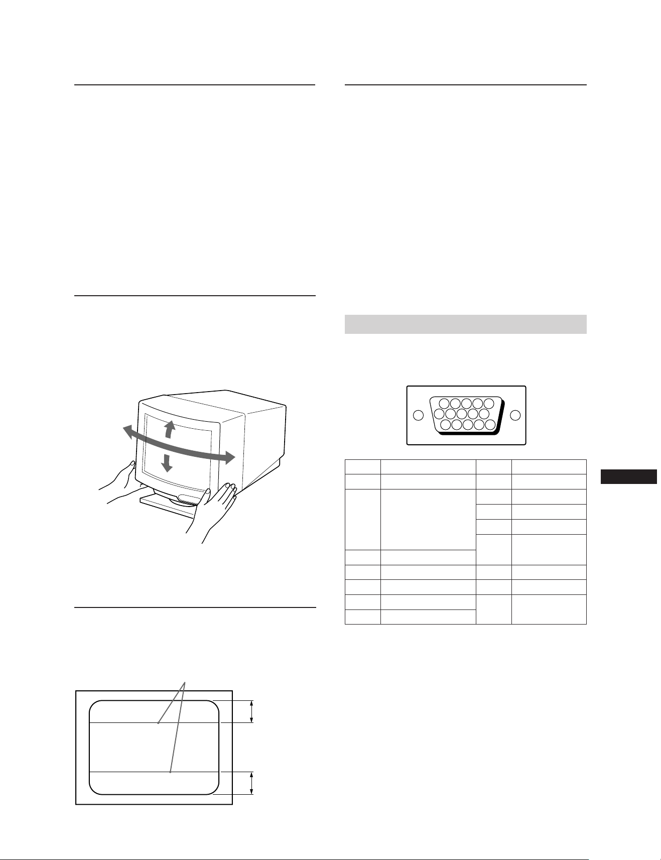
Technische DatenPlug and Play
Dieser Monitor entspricht den DDC-Standards (DDC =
Display Data Channel) DDC1, DDC2B und DDC2AB der
VESA. Ist das Gerät an ein DDC1-Hostsytem angeschlossen,
wird es gemäß dem VESA-Standard mit V.CLK
synchronisiert und gibt EDID-Signale (Extended Display
Identification) an die Datenleitung aus.
Ist das Gerät an ein DDC2B- oder DDC2AB-Hostsystem
angeschlossen, schaltet es automatisch auf den
entsprechenden Kommunikationsmodus um.
DDC™ ist ein Warenzeichen der Video Electronics Standard
Association.
Dreh- und
neigbarer Ständer
Mit dem dreh- und neigbaren Ständer können Sie das Gerät
in eine Position bringen, die Ihnen angenehm ist. Sie
können es horizontal um 90 Grad und vertikal um 20 Grad
schwenken bzw. neigen.
Stützen Sie das Gerät beim Einstellen der Position mit
beiden Händen an der Unterseite ab.
Bildröhre 0,30-mm-Streifenmaske,
53 cm diagonal gemessen
(max. 48,5 cm sichtbar) ,
90-Grad-Deflektion
Sichtbare Bildgröße ca. 388 × 292 mm (B/H)
Auflösung Horizontal: max. 1280 Punkte
Vertikal: max. 1024 Linien
Standard-Bildfläche ca. 373
Deflektionsfrequenz Horizontal: 30 bis 85 kHz
Eingangsspannung 220 bis 240 V Wechselstrom,
Leistungsaufnahme max. 150 W
Abmessungen ca. 472 × 493,5 × 501 mm (B/H/T)
Gewicht ca. 29,5 kg
×
280 mm (B/H)
oder
ca. 350
×
280 mm (B/H)
Vertikal: 48 bis 150 Hz
50 – 60 Hz, 1,2 A
Anschlußbelegung
Videosignalkabel (HD15-Anschluß)
Über das Kabel werden RGB-Videosignale (0,714 Vp-p,
positiv) und SYNC-Signale eingespeist.
15°
45°
45°
5°
Die
Dämpfungsdrähte
Bei einem weißen Hintergrund sind wie auf der Abbildung gezeigt
sehr dünne, horizontale Streifen auf dem Bildschirm zu sehen. Bei
diesen Streifen handelt es sich um Dämpfungsdrähte der
Streifenmaske im Inneren der Trinitron-Röhre. Sie dämpfen
Vibrationen der Streifenmaske und verhindern damit eine
Beeinträchtigung der Bildqualität.
Dämpfungsdrähte
876
5432
109
1514131211
Stift Nr.
8
9
10
11
12
13
14
15
Signal
Masse Blau
DDC + 5V*
Masse
–
Bidirektionaldaten
(SDA)*
H. Sync.
V. Sync.
Datenzeitgeber
*
(SCL)
1
Stift Nr.
1
Rot
2
Grün
(zusammengesetztes
Synchronisationssignal
auf Grün)
3
4
5
DDC Masse*
6
Masse Rot
7
Masse Grün
* DDC = Display Data Channel (VESA-Standard)
Änderungen an Design und technischen Daten bleiben
vorbehalten.
Signal
Blau
–
D
ca. 8 cm
ca. 8 cm
27
Page 28

Fehlerbehebung
Der folgende Abschnitt soll es Ihnen ermöglichen, eine
Fehlerursache selbst zu erkennen und den Fehler zu beheben.
Damit können Sie gegebenenfalls auf den technischen
Kundendienst verzichten und brauchen Ihre Arbeit nicht allzu
lange zu unterbrechen.
Kein Bild
/ Die Netzanzeige u und die Anzeige POWER
SAVING leuchten nicht.
— Das Netzkabel muß richtig angeschlossen
sein.
— Der Netzschalter muß auf „ON“ stehen.
/ Die Anzeige POWER SAVING leuchtet.
— Der Netzschalter des Rechners muß auf
„ON“ stehen.
— Sobald Sie eine Taste auf der Tastatur Ihres
Computers drücken, erscheint wieder ein
Bild auf dem Monitorbildschirm.
— Das Videokabel muß ordnungsgemäß
angeschlossen sein.
— Die Stifte im HD15-Anschluß des Kabels
dürfen nicht gebogen oder gedrückt sein.
— Die Videokarte muß korrekt in einem
geeigneten Bussteckplatz installiert sein.
— Das Videosynchronisationssignal muß für
den Monitor geeignet sein.
— Wenn Sie mit einem Macintosh-System
arbeiten, müssen Sie einen geeigneten
HD15-D15-Adapter verwenden.
/ Wenn Sie die oben angegebenen
Abhilfemaßnahmen durchführen, der Monitor
aber nicht in den normalen Betriebsmodus
schaltet.
— Lösen Sie das Videokabel vom HD15-
Anschluß, und halten Sie dann die Taste ¨
+ 2 Sekunden lang gedrückt, bis die
Farbbalken angezeigt werden. Schalten Sie
dann den Monitor am Netzschalter u aus
und wieder ein.
Wenn nun kein Bild auf dem
Monitorbildschirm erscheint, ist der
Monitor defekt.
/ Wenn die Netzanzeige u und/oder die
Energiesparanzeige POWER SAVING beide
blinken
— Schalten Sie den Monitor aus und wieder
ein. Blinken die Anzeigen nicht mehr,
befindet sich das Gerät im normalen
Betriebsmodus. Blinken sie noch, liegt
möglicherweise ein Defekt am Monitor vor.
/ Wenn Sie einen Macintosh-Computer
verwenden
— Prüfen Sie, ob die Mikroschalter am
Macintosh-Adapter Ihres Systems richtig
eingestellt sind. (siehe Dokumentation zum
Adapter).
Das Bild ist verzerrt.
/ Schlagen Sie in der Dokumentation zu Ihrer
Grafikkarte die geeignete Monitoreinstellung
für den Multiscan 20sfII nach.
/ Lesen Sie in dieser Anleitung nach, ob der
Grafikmodus und die Frequenz, mit der Sie
arbeiten möchten, unterstützt werden. Selbst
im geeigneten Bereich können einige
Videokarten einen Synchronisationsimpuls
haben, der für den Monitor zu kurz ist.
Die Farbe ist nicht gleichmäßig.
/ Betätigen Sie einmal den Netzschalter, um den
Entmagnetisierungszyklus zu aktivieren*.
Weiß sieht nicht weiß aus.
/ Stellen Sie über die Bildschirmanzeige mit den
Einstelloptionen die Farbtemperatur ein
(Seite 25).
/ Wenn Sie mit einem Macintosh-System
arbeiten, überprüfen Sie, ob die Mikroschalter
am Macintosh-Adapter korrekt auf ihr System
eingestellt sind (siehe Dokumentation zum
Adapter).
Das Bild auf dem Bildschirm ist nicht ordnungsgemäß
zentriert, oder die Größe stimmt nicht.
/ Stellen Sie die Werte mit Hilfe der Menüs
„CENTER“, „SIZE“ und „GEOMETRY“
korrekt ein (Seiten 23, 24).
/ Bei einigen Videomodi wird der Bildschirm
nicht bis zum Rand des Monitors ausgefüllt.
Für dieses Problem sind mehrere Faktoren
verantwortlich. Dieses Problem tritt in der
Regel bei hohen Auffrischungs-Timings und
bei Macintosh-Video-Timings auf.
Bildränder gekrümmt
/ Korrigieren Sie über die Bildschirmanzeige
"GEOMETRY" die Kissenverzeichnung (Seite
24).
Rote oder blaue Schatten an den Rändern weißer Linien
/ Stellen Sie über die Bildschirmanzeige
"CONVERGENCE"die Konvergenz ein (Seite
25).
Das Bild ist unscharf.
/ Stellen Sie die Werte mit Hilfe der Menüs
„CONTRAST“ und „BRIGHTNESS“ korrekt
ein (Seite 23). Die SVGA-Karten einiger
Hersteller haben einen zu hohen
Videoausgangspegel, der bei maximalem
Kontrast ein verschwommenes Bild erzeugt.
/ Betätigen Sie einmal den Netzschalter, um den
Entmagnetisierungszyklus zu aktivieren*.
/ Sind an den Bildrändem rote oder blaue
Schatten zu sehen, stellen Sie über die
Bildschirmanzeige die Konvergenz ein
(Seite 25).
Das Bild springt oder zittert.
/ Sie sollten Störquellen entfernen oder
abschirmen. Als Störquellen kommen alle
Geräte, von denen elektrische Strahlen oder
Magnetfelder ausgehen (z.B. elektrische
Ventilatoren, Leuchtstoffröhren und
Laserdrucker), in Frage.
/ Wenn sich in der Nähe dieses Monitors ein
anderer Monitor befindet, müssen Sie den
Abstand zwischen den beiden Monitoren
erhöhen, um die Interferenz zu verringern.
/ Sie sollten den Monitor versuchsweise an eine
andere Steckdose (möglichst innerhalb eines
anderen Stromkreises) anschließen.
/ Sie sollten den Monitor versuchsweise an
einen anderen Computer in einem anderen
Zimmer anschließen.
28
Page 29

Doppelte Konturen, Geisterbilder
/ Verwenden Sie keine
Videoverlängerungskabel und/oder VideoUmschaltgeräte. Solche Störungen könnnen
beispielsweise durch lange Kabel oder
schlechte Kontakte verursacht werden.
Zwei feine horizontale Linien werden angezeigt.
/ Diese Linien sind Dämpfungsdrähte und
stabilisieren die vertikal gestreifte
Streifenmaske. Diese Streifenmaske läßt mehr
Licht für den Bildschirm passieren, so daß die
Trinitron-Röhre mehr Farbe und Helligkeit
empfängt.
Ein Wellen- oder Ellipsen-Muster (Moiré-Muster)
erscheint.
/ Wegen der Zusammenwirkung von
Auflösung, Bildpunktdichte des Monitors und
Bildpunktdichte einiger Bildmuster kann bei
bestimmten Hintergrundeinstellungen,
besonders bei einem grauen Hintergrund, auf
dem Bildschirm ein Wellen- oder MoiréMuster erscheinen. Dies können Sie nur
beheben, indem Sie Ihr Desktop-Muster
ändern.
*
Mit der Entmagnetisierungsfunktion wird der
Metallrahmen der Kathodenstrahlröhre entmagnetisiert,
um ein neutrales Feld für einheitliche Farberzeugung zu
schaffen. Wenn ein zweiter
erforderlich ist, warten Sie mindestens 20 Minuten.
•Wenn Sie den Fehler nicht beheben können, rufen Sie
Ihren autorisierten Sony-Händler an. Sie sollten während
des Gesprächs Zugang zu dem Monitor haben.
•Notieren Sie die Modell- und Seriennummer Ihres
Monitors sowie Marke und Modell Ihres Rechners und
Ihrer Videokarte.
Entmagnetisierungszyklus
D
29
Page 30
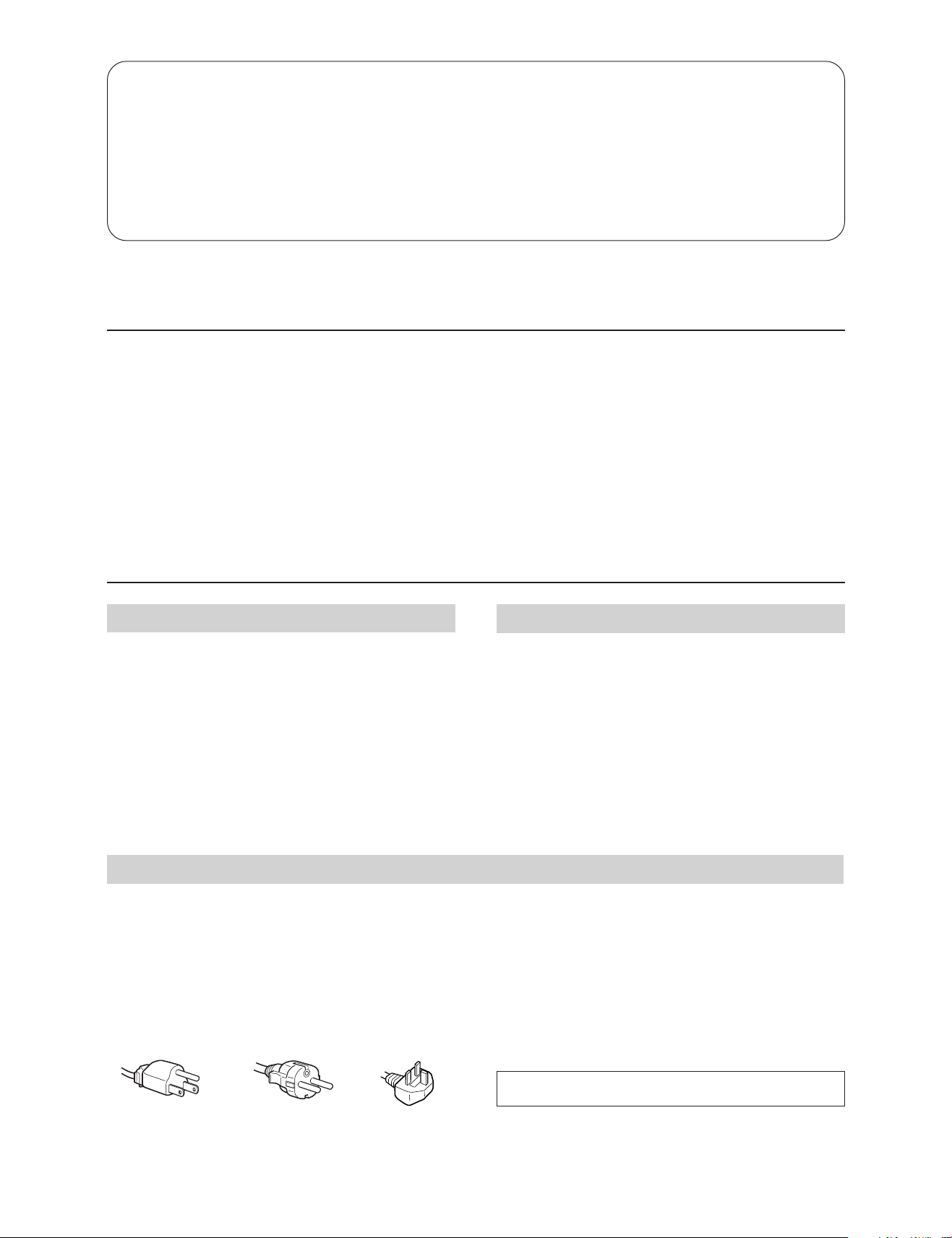
Indice
Introducción ...........................................................................30
Precauciones ...........................................................................30
Procedimientos iniciales .......................................................31
Uso del monitor .....................................................................31
Ajustes .....................................................................................32
Introducción de nuevos valores ..........................................35
Introducción
Enhorabuena por la adquisición del monitor de exploración
múltiple de la serie SF de Sony.
Este monitor incorpora 25 años de experiencia de Sony en
tecnología de pantallas Trinitron, garantizando un excelente
rendimiento, así como una notable fiabilidad.
El avanzado diseño de la serie SF junto con la tecnología
digital de exploración múltiple, permiten la sincronización
con cualquier modo de vídeo dentro de un amplio margen
de exploración. Además, los tres modos de color
Función de ahorro de energía.............................................. 35
Función Plug and Play ..........................................................36
Soporte basculante giratorio ................................................36
Hilos de amortiguación ........................................................36
Especificaciones ..................................................................... 36
Solución de problemas.......................................................... 37
predefinidos de fábrica y ajustables por el usuario
proporcionan una flexibilidad sin precedentes para obtener
en las impresiones los mismos colores que aparecen en
pantalla. Este monitor también se caracteriza por controles
digitales con la función OSD (indicación en pantalla).
Mediante la visualización del estado de control, es posible
realizar ajustes con facilidad. Todas estas características
proporcionan un alto rendimiento con la calidad y el
respaldo de Sony.
Precauciones
Instalación
•Coloque la unidad en un lugar debidamente ventilado
para evitar el recalentamiento interno. No sitúe la unidad
sobre superficies (alfombras, mantas, etc.) o cerca de
materiales (cortinas, tapices) que puedan bloquear los
orificios de ventilación.
•No instale la unidad cerca de fuentes de calor, como
radiadores o tubos de ventilación, ni la exponga a la luz
directa del sol, a polvo excesivo, o a vibraciones o
sacudidas mecánicas.
•Mantenga la unidad alejada de equipos que generen
campos magnéticos, como transformadores o líneas
eléctricas de alto voltaje.
Advertencia sobre la conexión de la alimentación
•Utilice un cable de alimentación adecuado al suministro
eléctrico local.
Para los usuarios de EE UU.
En caso contrario, este monitor no cumplirá las normas
FCC obligatorias.
Para los usuarios del R.U.
Si utiliza el monítor en el R.U., utilice el cable UK
suministrado con el enchufe UK.
Ejemplos de formas de enchufes:
Mantenimiento
•Limpie el exterior, el panel y los controles con un paño
suave ligeramente humedecido en una solución detergente
poco concentrada. No utilice ningún tipo de estropajo
abrasivo, limpiadores alcalinos, detergentes abrasivos ni
disolventes, como alcohol o bencina.
•Procure no friccionar, tocar ni golpear la superficie de la
pantalla con objetos puntiagudos o abrasivos, como un
bolígrafo o un destornillador. De lo contrario, este tipo de
contacto puede causar que el tubo de imagen se arañe.
•Tras apagar el monitor, espere al menos 30 segundos antes
de desconectar el cable de alimentación para permitir la
descarga de la electricidad estática acumulada en la
superficie del TRC.
•Tras acitivar la alimentación, el TRC se desmagnetiza
durante 5 segundos aproximadamente. Este proceso
genera un intenso campo magnético que puede alterar los
datos contenidos en las cintas o discos magnéticos situados
en las proximidades. Por ello, es aconsejable situar tales
materiales magnéticos lejos del monitor.
para tensiones de
100 a 120 V CA
30
para tensiones de
220 a 240 V CA
La toma de corriente debe instalarse en las proximidades
del monitor y ser fácilmente accesible.
Sólo para
240 V CA
Page 31
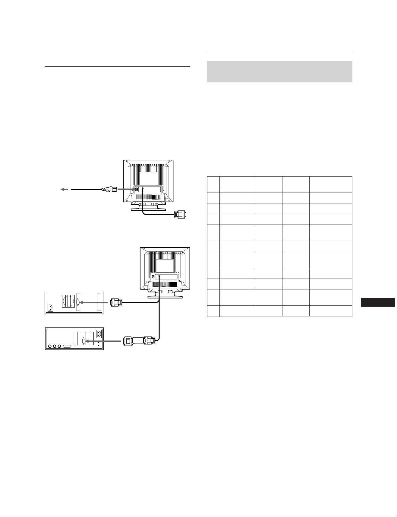
Procedimientos
Iniciales
Este monitor puede sincronizarse con cualquier sistema IBM
o compatible equipado con una tarjeta gráfica VGA o
superior. Aunque también puede sincronizare a otras
plataformas que utilicen frecuencias de barrido horizontal
comprendidas entre 30 y 85 kHz, incluidos los equipos
Macintosh y el sistema Power Macintosh, para ello se
precisa un cable adaptador. Consulte a su proveedor acerca
del adaptador que mejor se ajuste a sus necesidades.
Paso 1: Con el monitor apagado, enchufe el cable de
alimentación al monitor y el otro extremo a una
toma de corriente.
Uso del monitor
Modos predefinidos y de
usuario
El monitor Multiscan 20sfII cuenta con modos predefinidos
de fábrica para 10 de los más comunes estándares del sector,
lo que permite utilizarlo inmediatamente (plug and play).
Si utiliza un modo menos común, la tecnología de
multiexploración digital del Multiscan 20sfII realiza todos
los ajustes necesarios para garantizar una imagen de
máxima calidad con cualquier frecuencia de barrido
comprendida entre 30 y 85 kHz.
Sin embargo, debido a la amplia gama de tarjetas de vídeo
existente en el mercado, puede ser necesaria la sintonización
de precisión del centrado y tamaño vertical y horizontal.
Cable de alimentación
(suministrado)
a una toma de
corriente
Paso 2: Con el ordenador apagado, enchufe el cable de
señal de vídeo a la salida de vídeo.
Ordenador IBM o compatible
a la salida de vídeo
Ordenador Apple
Paso 3: Encienda el monitor y el ordenador.
Paso 4: En caso necesario, ajuste los controles de usuario
según sus preferencias.
Así se completa la instalación del Multiscan 20sfII.
Nota: Utilice el adaptador de conectores HD15 (hembra) -
HD15 (macho sin contacto núm. 9) (suministrado)
para un ordenador con DOS normal que no esté de
acuerdo con DDC2AB y que tenga el contacto núm. 9
sin conversión.
Adaptador Macintosh
(suministrado)
a la salida de vídeo
Resolución
Nº.
(puntos × líneas)
640 × 480
1
720 × 400
2
640 × 480
3
832 × 624
4
800 × 600
5
1024 × 768
6
1280 × 1024
7
1024 × 768
8
1152 × 870
9
1280 × 1024
10
Nota: Para usuarios de Windows
la tarjeta de vídeo o el programa de utilidades que
acompaña a la tarjeta gráfica para seleccionar la
mayor velocidad de regeneración de imagen
disponible, con el fin de obtener un rendimiento
óptimo del monitor.
Condiciones recomendadas de sincronización horizontal
El ancho de sincronización horizontal debe ser >4,8% del
tiempo horizontal total.
El ancho de supresión horizontal debe ser >3,0 µseg.
1) VGA es una marca comercial de IBM Corporation.
2) VESA es una marca comercial de Video Electronics
Standard Association.
3) Macintosh es una marca comercial de Apple Computer
Inc.
4) Windows® es una marca registrada de Microsoft
Corporation en los Estados Unidos de América y otros
países.
Frecuencia
horizontal
31.5 kHz
31.5 kHz
43.3 kHz
49.7 kHz
53.7 kHz
60.0 kHz
64.0 kHz
68.7 kHz
68.7 kHz
80.0 kHz
Frecuencia
vertical
60 Hz
70 Hz
85 Hz
75 Hz
85 Hz
75 Hz
60 Hz
85 Hz
75 Hz
75 Hz
®4)
Modo de
gráficos
VGA Graphic
VGA Text
VESA
Macintosh
16” Color
VESA
Macintosh
19” Color
VESA
VESA
Macintosh
21” Color
VESA
consulte el manual de
1)
2)
3)
2)
3)
2)
2)
3)
2)
1)
ES
31
Page 32

CENTER
CENTER
0 23
Ajustes
Al introducir una de las señales programadas, no es
necesario ajustar la imagen.
No obstante, puede ajustar la imagen según sus
preferencias. Para ello, realice el procedimiento que se
describe a continuación. Es posible ajustar todas las
opciones en OSD (indicación en pantalla). La opción
seleccionada aparecerá en OSD en color blanco.
Panel de control
RESET
COLOR
CONV
GEOM
Ajuste del brillo de la imagen
Los datos de ajuste se convierten en el ajuste común para
todas las señales de entrada.
1 Pulse el botón ¨ ?//.
Aparece la indicación “CONTRAST/BRIGHTNESS”
OSD (indicación pantalla).
CONTRAST BRIGHTNESS
23
80.0
kHz/75Hz
0
SIZE
p Antes de ajustar las opciones, active la unidad y
alimente la señal de vídeo del ordenador/estación de
trabajo conectado.
p Los ajustes se almacenarán automáticamente.
POWER
CENTER
SAVING
Ajuste de la posición de
centrado de la imagen
Los datos de ajuste se convierten en el ajuste único de la
señal de entrada recibida.
1 Pulse el botón CENTER.
Aparece la indicación “CENTER” OSD (indicación en
pantalla).
2 Pulse los botones ¨ ?// para ajustar el brillo de la
imagen.
? . . . para reducir el brillo
/ . . . para aumentar el brillo
La indicación “CONTRAST/BRIGHTNESS” OSD
desaparece 3 segundos después de soltar los botones.
Para reajustar, pulse el botón RESET mientras la función
OSD esté activada.
Ajuste del contraste de la
imagen
Los datos de ajuste se convierten en el ajuste común para
todas las señales de entrada.
1 Pulse el botón > >/..
Aparece la indicación “CONTRAST/BRIGHTNESS”
OSD (indicación en pantalla).
CONTRAST BRIGHTNESS
23
80.0
kHz/75Hz
0
2 Pulse los botones > >/. para ajustar el contraste de la
imagen.
> . . . para aumentar el contraste
. . . . para reducir el contraste
La indicación “CONTRAST/BRIGHTNESS” OSD
desaparece 3 segundos después de soltar los botones.
Para reajustar, pulse el botón RESET mientras la función
OSD esté activada.
32
2 Para realizar el ajuste vertical de la imagen
Pulse los botones > >/..
> . . . para desplazar la imagen hacia arriba
. . . . para desplazar la imagen hacia abajo
Para realizar el ajuste horizontal de la imagen
Pulse los botones ¨ ?//.
? . . . para desplazar la imagen a la izquierda
/ . . . para desplazar la imagen a la derecha
Para borrar la indicación “CENTER” OSD, vuelva a pulsar
el botón CENTER.
La indicación “CENTER” OSD desaparece automáticamente
10 segundos después de soltar los botones.
Para reajustar, pulse el botón RESET mientras la función
OSD esté activada.
Page 33

Ajuste del tamaño de la
imagen
Los datos de ajuste se convierten en el ajuste único de la
señal de entrada recibida.
1 Pulse el botón SIZE.
Aparece la indicación “SIZE” OSD (indicación en
pantalla).
SIZE
SIZE
2 Pulse los botones > >/..
> . . . para girar a la derecha
. . . . para girar a la izquierda
Para borrar la indicación “GEOMETRY” OSD, vuelva a
pulsar el botón GEOM.
La indicación “GEOMETRY” OSD desaparece
automáticamente 10 segundos después de soltar los
botones.
0 23
2 Para realizar el ajuste vertical de la imagen
Pulse los botones > >/..
> . . . para ampliar
. . . . para reducir
Para realizar el ajuste horizontal de la imagen
Pulse los botones ¨ ?//.
? . . . para reducir
/ . . . para ampliar
Para borrar la indicación “SIZE” OSD, vuelva a pulsar el
botón SIZE.
La indicación “SIZE” OSD desaparece automáticamente 10
segundos después de soltar los botones.
Para reajustar, pulse el botón RESET mientras la función
OSD esté activada.
Ajuste de la distorsión de
imagen
Los datos de ajuste se convierten en el ajuste único de la
señal de entrada recibida.
1 Pulse el botón GEOM.
Aparece la indicación “GEOMETRY” OSD (indicación
en pantalla).
GEOMETRY
GEOM
0 23
2 Pulse los botones ¨ ?//.
ES
Para reajustar, pulse el botón RESET mientras la función
OSD esté activada.
Ajuste de la rotación de la
imagen
Los datos de ajuste se convierten en el ajuste común para
todas las señales de entrada.
1 Pulse el botón GEOM.
Aparece la indicación “GEOMETRY” OSD (indicación
en pantalla).
GEOMETRY
GEOM
0 23
? . . . para reducir los lados de la imagen
/ . . . para aumentar los lados de la imagen
Para borrar la indicación “GEOMETRY” OSD, vuelva a
pulsar el botón GEOM.
La indicación “GEOMETRY” OSD desaparece
automáticamente 10 segundos después de soltar los
botones.
Para reajustar, pulse el botón RESET mientras la función
OSD esté activada.
33
Page 34

Ajustes
COLOR TEMPERATURE
9300K
6500K
5000K
SELECT
50
SET
Ajuste de la convergencia
Los datos de ajuste se convierten en el ajuste común para
todas las señales de entrada.
1 Pulse el botón CONV.
Aparece la indicación “CONVERGENCE” OSD
(indicación en pantalla).
CONVERGENCE
CONV
0 23
2 Para realizar el ajuste vertical
Pulse los botones > >/..
> . . . para desplazar el rojo (R) hacia arriba y el azul
(B) hacia abajo
. . . . para desplazar el rojo (R) hacia abajo y el azul
(B) hacia arriba
Para realizar el ajuste horizontal
Pulse los botones ¨ ?//.
Ajuste de la temperatura del
color
Los datos de ajuste seleccionados se convierten en el ajuste
común para todas las señales de entrada. (El ajuste de
fábrica es 9300K)
1 Pulse el botón COLOR.
Aparece la indicación “COLOR TEMPERATURE” OSD
(indicación en pantalla).
COLOR TEMPERATURE
COLOR
SELECT
2 Realice el ajuste con los botones > >/. y ¨ ?//.
Para seleccionar 9300K, 6500K o 5000K
Pulse los botones > >/..
Para obtener la temperatura de color que desee
comprendida entre 5000K y 9300K
1 Pulse los botones > >/. para seleccionar el modo
de usuario (
).
9300K
6500K
5000K
50
? . . . para desplazar el rojo (R) hacia la derecha y el
azul (B) hacia la izquierda
/ . . . para desplazar el rojo (R) hacia la izquierda y
el azul (B) hacia la derecha
Para borrar la indicación “CONVERGENCE” OSD, vuelva a
pulsar el botón CONV.
La indicación “CONVERGENCE” OSD desaparece
automáticamente 10 segundos después de soltar los
botones.
Para reajustar, pulse el botón RESET mientras la función
OSD esté activada.
34
2 Pulse los botones ¨ ?//.
? . . . menos temperatura (rojizo)
/ . . . más temperatura (azulado)
Si pulsa el botón > >/., obtendrá el último ajuste
introducido de la temperatura de color.
El ajuste de fábrica de la temperatura de color que puede
modificar el usuario es 6500K.
Para borrar la indicación “COLOR TEMPERATURE” OSD,
vuelva a pulsar el botón COLOR.
La indicación “COLOR TEMPERATURE” OSD desaparece
automáticamente 10 segundos después de soltar los
botones.
Para reajustar, pulse el botón RESET mientras la función
OSD esté activada.
Page 35

Restauración de los valores
predefinidos de fábrica
Restauración de una opción de ajuste
Pulse el botón correspondiente a la opción que quiere
recuperar, y antes de que desaparezca OSD (indicación en
pantalla), pulse RESET.
Restauración simultánea de los datos de
ajuste de brillo, contraste, tamaño,
centrado, distorsión de la imagen y
temperatura del color (para la señal
recibida)
Introducción de
nuevos valores
Si utiliza un modo de vídeo distinto de los 10 modos
predefinidos de fábrica, es posible que sea preciso realizar
una sintonización de precisión para optimizar la imagen
según sus preferencias. Para ello, basta ajustar el monitor
siguiendo las instrucciones anteriormente descritas. Los
ajustes se almacenarán automáticamente y se restaurarán
siempre que utilice dicho modo.
Es posible almacenar en memoria un total de 15 modos
definidos por el usuario. Si se introduce un decimosexto
modo, éste sustituirá al primero.
Función de ahorro
Pulse el botón RESET con algún objeto puntiagudo, como
un bolígrafo, durante 1 segundo cuando no se muestre
ninguna indicación OSD.
RESET
Restauración de todos los datos de ajuste
según los valores predefinidos de fábrica
Mantenga pulsado el botón RESET durante más de 2
segundos. De esta forma, todos los datos de ajuste, incluidos
el brillo y el contraste, recuperarán los valores predefinidos
de fábrica.
RESET
de energía
El monitor cumple las directrices de ahorro de energía
establecidas por EPA (Energy Star Program), así como la
normativa más exigente TCO95 (NUTEK). Puede reducir el
consumo de energía si se utiliza juntamente con un
ordenador equipado con Display Power Management
Signaling (DPMS). Cuando detecta la ausencia de señal de
sincronización procedente del ordenador, el monitor reduce
el consumo de energía de la siguiente forma:
PRECAUCION: Si se contraste el interruptor de corriente sin
que exista una señal de video de entrada, la
función de ahorro de energía situará al
monitor en estado activo-inactivo. En el
momento en que el monitor detecte señales
de sincronismo horizontal y vertical, se
situará automáticamente en estado de
funcionamiento normal.
Modo
Funcionamiento
1
(primer paso de
2
ahorro de energía)
(segundo paso de
3
ahorro de energía)
Activo-inactivo
(tercer paso de
4
ahorro de energía)
5
Estado
normal
En espera
Reposo
Apagado
Consumo
de energía
100%
Aprox. 70%
Aprox. 10%
Aprox. 4%
0%
Tiempo de
reanudación
necesario
—
Aprox. 3 seg.
Aprox. 3 seg.
Aprox. 10
seg.
—
Indicador
POWER
SAVING
apagado
naranja
iluminado
naranja
iluminado
naranja
iluminado
apagado
Indicador de
alimentación
u
verde
iluminado
verde
iluminado
verde
iluminado
apagado
apagado
ES
35
Page 36

EspecificacionesFunción Plug and
Play
Este monitor cumple las normas DDC™1, DDC2B y
DDC2AB, que son las normas de Canal de Datos de
Visualización (DDC) de VESA.
Cuando se conecta un sistema central DDC1, el monitor se
sincroniza con V.CLK de acuerdo con las normas VESA y
transmite la Identificación de Visualización Extendida
(EDID) a la línea de datos.
Cuando se conecta un sistema central DDC2B o DDC2AB, el
monitor conmuta automáticamente a cada una de las
comunicaciones.
DDC™ es una marca registrada de Video Electronics Standard
Association.
Soporte basculante
giratorio
Con el soporte basculante giratorio, es posible ajustar el
ángulo de visualización de esta unidad (90° horizontalmente
y 20° verticalmente).
Para girar la unidad vertical y horizontalmente, sujétela por
la parte inferior con las dos manos.
15°
45°
45°
Tubo de imagen con un Paso de rejilla de apertura de
0,30mm; 20 pulgadas en diagonal,
deflexión, 90 grados
Tamaño de imagen de visualizable
388 × 292 mm (an/al) aprox.
Imagen de visualización de 19,1”
Resolución Horizontal: Máx. 1280 puntos
Vertical: Máx. 1024 líneas
Área estándar de la imagen
373 × 280 mm (an/al) aprox.
o
350 × 280 mm (an/al) aprox.
Frecuencia de deflexión
Horizontal: 30 a 85 kHz
Vertical: 48 a 150 Hz
Tensión/intensidad de entrada CA
100 a 120 V, 50/60 Hz, 1,7 A
220 a 240 V, 50 – 60 Hz, 1,2 A
Consumo de energía Máx. 150 W
Dimensiones 472 × 493,5 × 501 mm (an/al/prf)
aprox.
Masa 29,5 kg aprox.
Asignación de terminales
Cable de señal de vídeo (HD15) (macho)
El cable acepta señales de vídeo RGB (0,714 Vp-p, positivas),
y señales de sincronización.
5°
Hilos de
amortiguación
Si utiliza un fondo blanco, en la pantalla aparecen estrías
horizontales muy finas como se muestra a continuación.
Estas estrías son hilos de amortiguación que están
conectados a la rejilla de apertura dentro del tubo Trinitron
y que sirven para absorber las vibraciones de la rejilla de
apertura con el fin de evitar que afecten a la calidad de la
imagen.
Hilos de amortiguación
8 cm aprox.
876
N°. de
terminal
8
9
10
11
12
13
14
15
5432
109
1514131211
Señal
Masa de azul
+5V de DDC*
Masa
—
Datos
bidireccionales
(SDA)*
Sincronización
horizontal
Sincronización
vertical
Reloj de datos
(SLC)*
1
N°. de
terminal
1
2
3
4
5
6
7
Norma de Canal de Datos de Visualización (DDC) por
*
VESA
Señal
Rojo
Verde
(sincronización
compuesta de
verde)
Azul
—
Masa de DDC*
Masa de rojo
Masa de verde
36
8 cm aprox.
Diseño y especificaciones sujetos a cambio sin previo aviso.
Page 37

Solución de problemas
Esta sección le ayudará a identificar los posibles problemas,
para que no tenga necesidad de ponerse en contacto con el
servicio técnico e interrumpir así su productividad.
No aparece ninguna imagen
/ Si no se iluminan los indicadores u
(alimentación) ni POWER SAVING
— Compruebe si el cable de alimentación está
debidamente conectado.
— Compruebe si el interruptor de corriente se
encuentra en la posición “ON”.
/ Si se ilumina el indicador POWER SAVING
— Compruebe si el interruptor de corriente
del ordenador se encuentra en la posición
“ON”.
— El monitor se recuperá al pulsar cualquier
tecla del teclado del ordenador.
— Compruebe si el cable de vídeo se encuentra
debidamente conectado.
— Compruebe que el conector HD15 del cable
no tenga clavijas torcidas o arrancadas.
— Compruebe si la tarjeta de vídeo se
encuentra correctamente conectada a la
ranura de bus.
— Compruebe si la señal de sincronización de
vídeo se encuentra en el margen
especificado para el monitor.
— Si utiliza un sistema Macintosh, compruebe
si utiliza un adaptador HD15-D15 adecuado
para dicho sistema.
/ Si una vez realizados los procedimientos
anteriores el monitor no se recupera
— Desenchufe el cable de vídeo (HD15) y, a
continuación, mantenga pulsado el botón
¨+ durante 2 segundos para que aparezcan
las barras de color. Después, apague y
vuelva a encender el monitor pulsando el
interruptor de alimentación u.
Si el monitor no se recupera significa que
está estropeado.
/ Si parpadean los indicadores u (alimentación)
y/o POWER SAVING
— Apague y vuelva a encender el monitor. Si
el indicador no parpadea, el monitor se
encuentra en estado normal.
Si el indicador parpadea todavia, se ha
producido un fallo potencial del monitor.
/ Si su ordenador es de sistema Macintosh
— Compruebe que los microinterruptores
estén correctamente ajustados en el
adaptador Macintosh de su sistema.
(Consulte el manual del adaptador.)
El color no es uniforme
/ Pulse una vez el interruptor de corriente para
iniciar el ciclo de desmagnetización
automática*.
El color blanco no parece blanco
/ Ajuste la temperatura del color con la
indicación “COLOR TEMPERATURE”en OSD
(página 34).
/ Si su ordenador es de sistema Macintosh,
compruebe que los microinterruptores estén
ajustados correctamente en el adaptador.
Macintosh de su sistema. (Consulte el manual
del adaptador.)
La imagen no está centrada en la pantalla o tiene un
tamaño incorrecto
/ Realice el ajuste con las indicaciones
“CENTER”, “SIZE” y “GEOMETRY” en OSD
(páginas 32, 33).
/ Algunos modos de vídeo no llenan
completamente la pantalla hasta el borde. No
hay una respuesta única para resolver este
problema, que suele estar relacionado con
altas frecuencias de barrido y con las
frecuencias de vídeo de los sistemas
Macintosh.
Los bordes de la imagen son curvos
/ Ajuste la distorsión con la
indicación“GEOMETRY” en OSD (página 33).
Las líneas blancas muestran sombras rojas o azules en
los bordes
/ Ajuste la convergencia con la indicación
“CONVERGENCE” en OSD (página␣ 34).
La imagen aparece borrosa
/ Ajuste el contraste y el brillo con las
indicaciones “CONTRAST” y “BRIGHTNESS”
en OSD (página 32). Hemos descubierto que
las tarjetas de vídeo de algunas marcas
utilizan un nivel de salida de video excesivo,
el cual da origen a imágenes borrosas con
máximo contraste*.
/ Pulse una vez el interruptor de corriente para
iniciar la ciclo de desmagnetización
automática*.
/ Si en los bordes de la imagen aparecen
sombras rojas o azules, ajuste la convergencia
con la indicación “CONVERGENCE” en OSD
(página 34).
E
Aparecen rayas en la imagen
/ Consulte en el manual de la tarjeta gráfica el
ajuste adecuado para el monitor Multiscan
20sfII.
/ Consulte este manual y compruebe si se
admite el modo gráfico y la frecuencia que
está tratando de utilizar. Aun funcionando
dentro del margen adecuado, algunas tarjetas
de vídeo utilizan un impulso de sincronía
demasiado corto para que el monitor se
sincronice debidamente.
La imagen salta o sufre oscilaciones
/ Aisle y elimine cualquier fuente que pueda
emitir campos eléctricos o magnéticos. Las
causas comunes de este síntoma son
ventiladores eléctricos, lámparas
fluorescentes, impresoras láser, etc.
/ Si tiene instalado otro monitor en las
inmediaciones de este, aumente la distancia
entre ambos para reducir las interferencias.
/ Pruebe a enchufar el monitor en un
tomacorriente de CA diferente, a ser posible
de un circuito diferente.
/ Pruebe a utilizar el monitor con un ordenador
o en una sala diferentes.
37
Page 38

Solución de problemas
La imagen se ve con imágenes fantasma
/ Cuando se produzca este síntoma, no utilice
cables prolongadores de vídeo ni cajas
conmutadoras. La longitud excesiva de los
cables o una conexión débil puede producir
este síntoma.
Se observan dos líneas horizontales finas
/ Estas líneas sirven para estabilizar la rejilla de
apertura vertical. La rejilla de apertura admite
el paso de mayor cantidad de luz a través de la
pantalla, aumentando así la intensidad del
color y el brillo del TRC de Trinitron.
Se observa en la imagen una trama ondulada o elíptica
(efecto muaré)
/ Debido a la relación entre la resolución, la
densidad de punto del monitor y algunas
tramas de imagen, determinados fondos de
pantalla, especialmente los de color gris,
muestran a veces un efecto muaré. La única
forma de eliminarlo es cambiar la trama del
escritorio.
*La finalidad de esta función es desmagnetizar el
bastidor metálico del TRC para obtener un campo
neutro que uniformiza la reproducción de los colores. Si
necesita iniciar un segundo ciclo de desmagnetización
automática, deje que transcurran al menos 20 minutos.
•Si el problema continúa, póngase en contacto con el
distribuidor autorizado de Sony más próximo.
•Tome nota del modelo y número de serie de su monitor,
asi como de la marca y modelo del ordenador y la tarjeta
de vídeo.
38
Page 39

Indice
Introduzione ...........................................................................39
Precauzioni .............................................................................39
Per iniziare ..............................................................................40
Uso del monitor .....................................................................40
Regolazioni .............................................................................41
Nuove sincronizzazioni ........................................................44
Introduzione
Complimenti per l’acquisto di un monitor Multiscan serie
SF della Sony!
Questo monitor incorpora oltre 25 anni di esperienza della
Sony con la tecnologia dei display Trinitron assicurando
resa e affidabilità eccellenti.
Il design all’avanguardia della serie SF insieme alla
tecnologia Digital Multiscan permettono la sincronizzazione
con qualsiasi modo video entro la sua ampia gamma di
scansione. Inoltre, i tre modi colore preimpostati dalla
Precauzioni
Funzione di risparmio energetico .......................................44
Uso immediato del monitor .................................................45
Uso del sistema di orientamento ........................................45
Cavi di smorzamento ............................................................45
Specifiche ................................................................................45
Soluzione dei problemi .........................................................46
fabbrica e i tre modi colore regolabili dall’utente offrono una
flessibilità senza precedenti nell’ottenere grossa somiglianza
tra i colori su schermo e quelli sugli stampati. Questo
monitor è inoltre dotato di comandi digitali con indicazioni
a schermo. La regolazione è facilitata dalla visualizzazione
dell’istruzione dei comandi. Questo monitor racchiude
complessivamente prestazioni incredibili e la qualità e il
supporto tipici dalla Sony.
Installazione
•Consentire un’adeguata circolazione d’aria per prevenire il
surriscaldamento interno dell’apparecchio. Non collocare
l’apparecchio su superfici (come tappeti e coperte) o vicino
a tessuti (tende, drappeggi, ecc.) che possano ostruire le
prese di ventilazione.
•Non installare l’apparecchio in prossimità di fonti di
calore, come termosifoni o condotti d’aria calda, oppure in
luoghi esposti alla luce diretta del sole, eccessivamente
polverosi o soggetti a vibrazioni meccaniche o scosse.
•Non collocare l’apparecchio in prossimità di dispositivi
che generano campi magnetici, come ad esempio
adattatori o linee di alta tensione.
Manutenzione
•Pulire il rivestimento, il pannello di vetro ed i comandi con
un panno morbido leggermente inumidito con una blanda
soluzione detergente. Non usare alcun tipo di straccio
graffiante, pulitore alcalino, polvere abrasiva o solventi
come alcool o benzina.
•Non strofinare, toccare o picchiettare sulla superficie dello
schermo con oggetti appuntiti o abrasivi, come una penna
a sfera o un cacciavite. Altrimenti tali tipi di contatto
possono causare graffiature sul cinescopio.
Avvertenza sui collegamenti per l’alimentazione
•Usare il cavo di alimentazione in dotazione.
Per la clientela negli U.S.A.
Se non si utilizza il cavo in dotazione, il monitor non sarà
conforme agli standard FCC obbligatori.
Per la clientela nel Regno Unito
Se si utilizza il monitor nel Regno Unito, utilizzare il cavo
in dotazione con una spina per il Regno Unito.
per CA da 100-120 V per CA da 220-240 V solo per CA da 240 V
•Prima di scollegare il cavo di alimentazione, attendere
almeno 30 secondi dallo spegnimento dell’apparecchio per
consentire la dispersione dell’elettricità statica sulla
superficie del tubo catodico.
•Appena l’apparecchio viene acceso, il tubo catodico viene
smagnetizzato per cinque secondi circa. Questa
operazione determina un forte campo magnetico attorno
alla lunetta che può danneggiare i dati di dischi o nastri
magnetici situati nelle immediate vicinanze. Allontanare
l’apparecchio di registrazione magnetica e i nastri/dischi
da questo monitor.
La presa di rete deve essere situata in prossimità
dell’apparecchio e deve essere facilmente accessibile.
I
39
Page 40

Per iniziare
Uso del monitor
Questo monitor può sincronizzarsi con qualsiasi sistema
IBM o compatibile in grado di utilizzare la capacità grafica
VGA o superiore. Inoltre, questo monitor può sincronizzarsi
con sistemi di piattaforme diverse a frequenze orizzontali
comprese tra 30 e 85 kHz, inclusi i sistemi Macintosh e
Power Macintosh; tuttavia, è necessario l’uso di un
adattatore del cavo. Rivolgersi al proprio rivenditore per
farsi consigliare sul tipo di adattatore più conforme alle
proprie esigenze.
Punto 1: con il monitor spento, collegare il cavo di
alimentazione al monitor e l’altro capo alla presa
di rete.
Cavo di alimentazione
(in dotazione)
alla presa di rete
Punto 2: con il computer spento, collegare il cavo del
segnale video all’uscita video.
Computer IBM o compatibile
all’uscita video
Modi preimpostati e modi utente
Il Multiscan 20sfII dispone di modi preimpostati dalla
fabbrica relativi ai 10 standard industriali che consentono
l’uso immediato dell’apparecchio.
Per quanto riguarda i modi meno comuni, la tecnologia
Digital Multiscan del Multiscan 20sfII effettua tutte le
impostazioni più complesse necessarie ad assicurare un’alta
qualità d’immagine a qualsiasi frequenza compresa tra 30 e
85 kHz.
Data la varietà delle schede video presenti sul mercato, può
essere necessario che l’utente
sintonizzi la centratura e le dimensioni verticali/orizzontali.
Risoluzione
N.
(punti × righe)
640 × 480
1
720 × 400
2
640 × 480
3
832 × 624
4
800 × 600
5
1024 × 768
6
1280 × 1024
7
1024 × 768
8
1152 × 870
9
1280 × 1024
10
Frequenza
orizzontale verticale
31,5 kHz
31,5 kHz
43,3 kHz
49,7 kHz
53,7 kHz
60,0 kHz
64,0 kHz
68,7 kHz
68,7 kHz
80,0 kHz
Frequenza
60 Hz
70 Hz
85 Hz
75 Hz
85 Hz
75 Hz
60 Hz
85 Hz
75 Hz
75 Hz
Modo grafico
VGA Graphic
VGA Text
VESA
Macintosh
16” a colori
VESA
Macintosh
19” a colori
VESA
VESA
Macintosh
21” a colori
VESA
1)
2)
3)
2)
3)
2)
2)
3)
2)
1)
Computer Apple
Adattatore per il
Macintosh
(in dotazione)
all’uscita video
Punto 3: accendere il monitor e il computer.
Punto 4: se occorre, regolare i controlli dell’utente
secondo le proprie esigenze.
L’installazione del Multiscan 20sfII è così completata. Il
monitor è pronto all’uso.
Nota: Usare l’adattatore HD15 (femmina)-HD15(maschio
senza pin n. 9) (in dotazione) per computer DOS che
non siano conformi con DDC 2AB e con il pin n. 9
scollegato.
®4)
Nota: E necessario che gli utenti di Windows
consultino
il manuale della scheda video o il programma di
utilità fornito insieme alla scheda e selezionino il
valore di rinfresco più alto per sfruttare al meglio le
prestazioni del monitor.
Condizioni di sincronizzazione orizzontale raccomandate
L’ampiezza di sincronizzazione orizzontale deve essere:
>4,8% della sincronizzazione orizzontale totale.
L’ampiezza di oscuramento orizzontale deve essere:
>3,0 µsec.
1) VGA è un marchio registrato della IBM Corporation.
2) VESA è un marchio registrato della Video Electronics
Standard Association.
3) Macintosh è un marchio registrato della Apple Computer
Inc.
4) Windows
®
è un marchio registrato della Microsoft
Corporation negli Stati Uniti e/o negli altri paesi.
40
Page 41
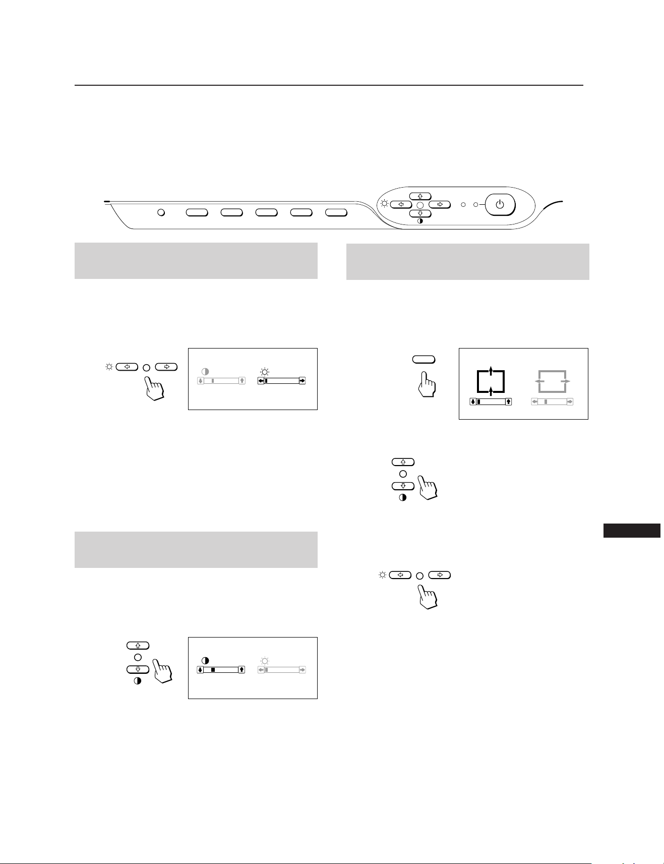
CENTER
CENTER
0 23
Regolazioni
Quando uno dei segnali di preselezione viene inserito, non è
necessaria alcuna regolazione.
È possibile tuttavia regolare l’immagine secondo le proprie
preferenze seguendo la procedura indicata di seguito.
Tutti gli elementi possono essere regolati sull’OSD (On
Screen Display). Nella visualizzazione a schermo la voce che
si desidera regolare viene indicata in bianco.
Pannello di controllo
RESET
COLOR
CONV
GEOM
SIZE
Regolazione della luminosità
dell’immagine
I dati della regolazione diventano l’impostazione comune di
tutti i segnali d’ingresso.
1 Premere il tasto ¨ ?//.
Il controllo “CONTRAST/BRIGHTNESS” OSD appare.
CONTRAST BRIGHTNESS
23
80.0
kHz/75Hz
0
p Prima di regolare gli elementi, accendere l’apparecchio
e alimentare il segnale del video dal computer o dalla
stazione di lavoro ad esso collegati.
p Tutte le regolazioni vengono memorizzate
automaticamente.
POWER
CENTER
SAVING
Regolazione della centratura
dell’immagine
I dati della regolazione diventano l’unica impostazione per
il segnale di ingresso ricevuto.
1 Premere il tasto CENTER.
Il controllo “CENTER” OSD appare.
2 Premere i tasti ¨ ?//. Per regolare la luminosità
dell’immagine.
? . . . per ridurre la luminosità
/ . . . per aumentare la luminosità
Il controllo “CONTRAST/BRIGHTNESS” OSD scompare 3
secondi dopo il rilascio del tasto.
Per reimpostare, premere il tasto RESET mentre il controllo
a schermo è attivo.
Regolazione del contrasto
dell’immagine
I dati della regolazione diventano l’impostazione comune di
tutti i segnali d’ingresso.
1 Premere il tasto > >/..
Il controllo “CONTRAST/BRIGHTNESS” OSD appare.
CONTRAST BRIGHTNESS
23
80.0
kHz/75Hz
2 Premere i tasti > >/.. Per regolare il contrasto
dell’immagine.
> . . . per aumentare il contrasto
. . . . per ridurre il contrasto
0
2 Per la regolazione verticale
Premere i tasti > >/..
> . . . per alzare l’immagine
. . . . per abbassare l’immagine
Per la regolazione orizzontale
Premere i tasti ¨ ?//.
? . . . per spostare l’immagine a sinistra
/ . . . per spostare l’immagine a destra
Per eliminare il controllo “CENTER” OSD, premere di
nuovo il tasto CENTER.
Il controllo “CENTER” OSD scompare automaticamente 10
secondi dopo il rilascio dei tasti.
Per reimpostare, premere il tasto RESET mentre il controllo
a schermo è attivo.
I
Il controllo “CONTRAST/BRIGHTNESS” OSD scompare 3
secondi dopo il rilascio del tasto.
Per reimpostare, premere il tasto RESET mentre il controllo
a schermo è attivo.
41
Page 42
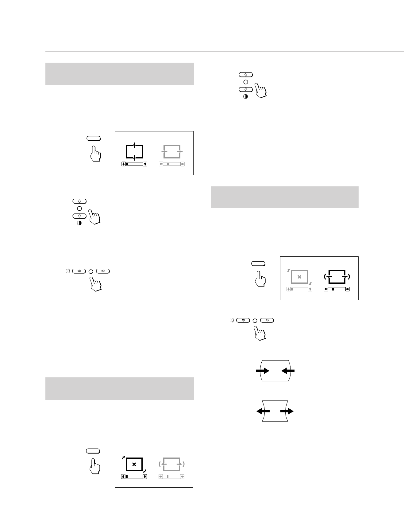
Regolazioni
Regolazione della
dimensione dell’immagine
I dati della regolazione diventano l’unica impostazione per
il segnale di ingresso ricevuto.
1 Premere il tasto SIZE.
Il controllo “SIZE” OSD appare.
SIZE
SIZE
0 23
2 Per la regolazione verticale
Premere i tasti > >/..
> . . . per ingrandire
. . . . per diminuire
Per la regolazione orizzontale
Premere i tasti ¨ ?//.
2 Premere i tasti > >/..
> . . . per una rotazione in senso orario
. . . . per una rotazione in senso antiorario
Per eliminare il controllo “GEOMETRY” OSD, premere di
nuovo il tasto GEOM.
Il controllo “GEOMETRY” OSD scompare automaticamente
10 secondi dopo il rilascio dei tasti.
Per reimpostare, premere il tasto RESET mentre il controllo
a schermo è attivo.
Regolazione della distorsione
dell’immagine a cuscino
I dati della regolazione diventano l’unica impostazione per
il segnale di ingresso ricevuto.
1 Premere il tasto GEOM.
Il controllo “GEOMETRY” OSD appare.
GEOMETRY
GEOM
? . . . per diminuire
/ . . . per ingrandire
Per eliminare il controllo “SIZE” OSD, premere di nuovo il
tasto SIZE.
Il controllo “SIZE” OSD scompare automaticamente 10
secondi dopo il rilascio dei tasti.
Per reimpostare, premere il tasto RESET mentre il controllo
a schermo è attivo.
Regolazione della rotazione
dell’immagine
I dati della regolazione diventano l’impostazione comune
per tutti i segnali di ingresso.
1 Premere il tasto GEOM.
Il controllo “GEOMETRY” OSD appare.
GEOMETRY
GEOM
0 23
0 23
2 Premere i tasti ¨ ?//.
? . . . per restringere i bordi dell’immagine
/ . . . per espandere i bordi dell’immagine
Per eliminare il controllo “GEOMETRY” OSD, premere di
nuovo il tasto GEOM.
Il controllo “GEOMETRY” OSD scompare automaticamente
10 secondi dopo il rilascio dei tasti.
Per reimpostare, premere il tasto RESET mentre il controllo
a schermo è attivo.
42
Page 43
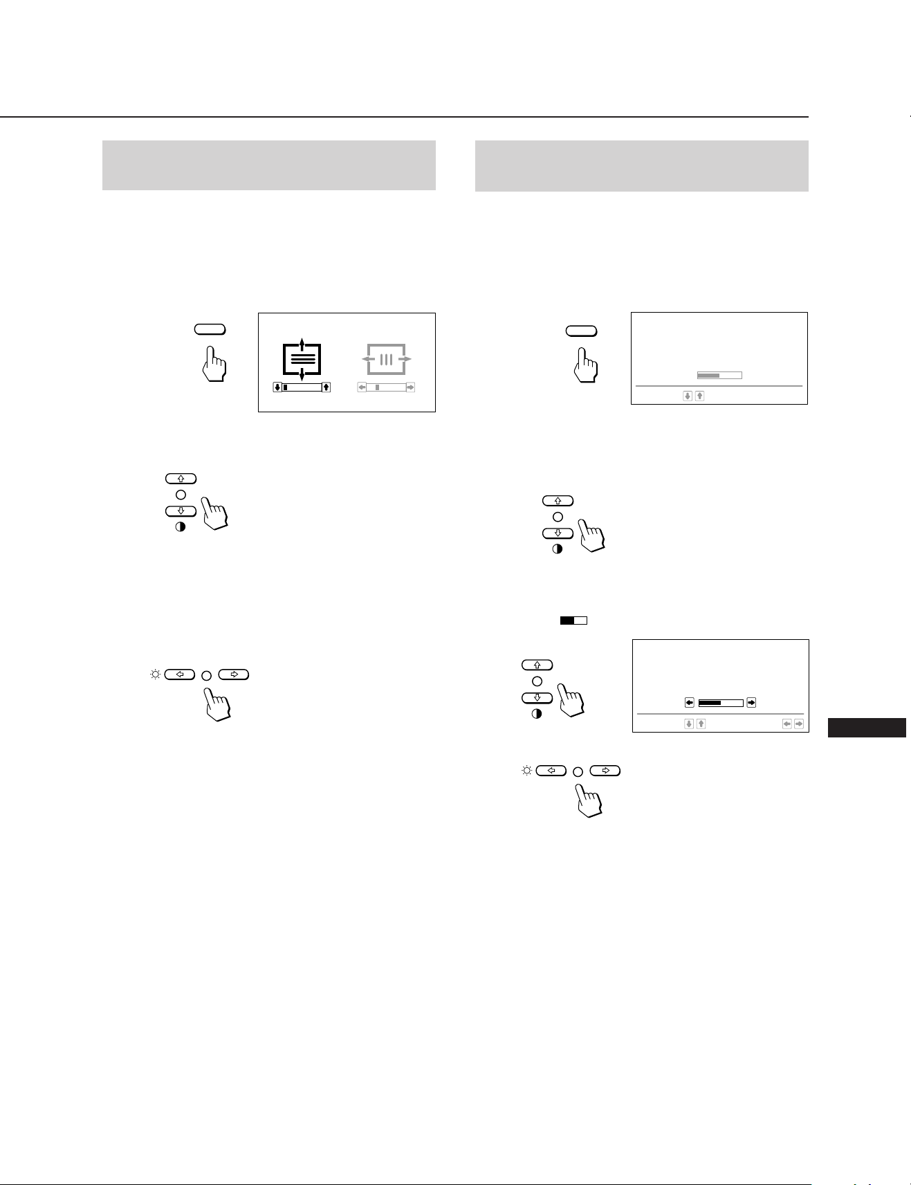
COLOR TEMPERATURE
9300K
6500K
5000K
SELECT
50
SET
Regolazione della
convergenza
Impostazione della
temperatura di colore
I dati della regolazione diventano l’impostazione commune
per tutti i segnali.
1 Premere il tasto CONV.
Sullo schermo compare il controllo “CONVERGENCE”
OSD appare.
CONVERGENCE
CONV
0 23
2 Per la regolazione verticale
Premere il tasti > >/..
> . . . Per spostare Red (R) verso il l’alto e Blue verso
basso (B).
. . . . Per spostare Red (R) verso basso e Blue (B)
verso il l’alto.
Per la regolazione orizzontale
Premere il tasti ¨ ?//.
La temperatura di colore selezionata diventa l’impostazione
comune per tutti i segnali di ingresso. (L’impostazione di
fabbrica è 9300K)
1 Premere il tasto COLOR.
Il controllo “COLOR TEMPERATURE” OSD appare.
COLOR TEMPERATURE
COLOR
SELECT
9300K
6500K
5000K
50
2 Regolare tramite i tasti > >/. e ¨ ?//.
Per selezionare 9300K, 6500K o 5000K
Premere i tasti > >/..
Per ottenere la temperatura di colore desiderata
compresa fra i valori 5000K e 9300K
1 Premere i tasti > >/. per selezionare il modo
utente (
).
? . . . Per spostare Red (R) a destra e Blue (B) a
sinistra.
/ . . . Per spostare Red (R) a sinistra e Blue (B) a
destra.
Per eliminare il controllo “CONVERGENCE” OSD, premere
di nuovo il tasto CONV.
Il controllo “CONVERGENCE” OSD scompare
automaticamente 10 secondi dopo il rilascio dei tasti.
Per reimpostare, premere il tasto RESET mentre il controllo
a schermo è attivo.
I
2 Premere i tasti ¨ ?//.
? . . . per temperature più basse (tendente al rosso)
/ . . . per temperature più alte (tendente al blu)
L’ultima temperatura di colore che è stata definita viene
ripristinata premendo il tasto > >/..
La preselezione di fabbrica è 6500K per la temperatura
di colore regolabile dall’utente.
Per eliminare il controllo “COLOR TEMPERATURE” OSD,
premere di nuovo il tasto COLOR.
Il controllo “COLOR TEMPERATURE” OSD scompare
automaticamente 10 secondi dopo il rilascio dei tasti.
Per reimpostare, premere il tasto RESET mentre il controllo
a schermo è attivo.
43
Page 44

Regolazioni
Nuove sincronizzazioni
Ripristino delle impostazioni
di fabbrica
Premere il tasto corrispondente al dato desiderato, poi
premere il tasto RESET prima che scompaia l’indicazione a
schermo.
Per reimpostare i dati di regolazione
della luminosità, del contrasto, della
dimensione, dellacentratura poi
temperatura di colore in una sola
operazione (per il segnale ricevuto)
Premere il tasto RESET con la punta di una penna, ad
esempio, per 1 secondo quando sullo schermo non è
presente nessuna indicazione.
RESET
Per ripristinare tutti i dati di regolazione
di fabbrica
Quando viene utilizzato un modo video diverso dai 10 modi
impostati dalla fabbrica, si può rivelare necessario effettuare
alcune regolazioni di messa a punto per ottimizzare la
visualizzazione secondo le personali preferenze. Limitarsi
alla configurazione dei monitor in base alle precedenti
istruzioni. Le regolazioni verranno memorizzate
automaticamente e potranno essere utilizzate durante un
successivo utilizzo del modo.
La memoria può contenere fino a 15 modi definiti
dall’utente. Se viene inserito un sedicesimo modo, esso
prenderà il posto del primo.
Funzione di risparmio
energetico
Questo monitor è conforme alle direttive dell’EPA (Energy
Star Program), nonché alle più rigorose direttive TCO95
(NUTEK). È in grado di ridurre il consumo di energia
elettrica se utilizzato con un computer dotato di DPMS
(Display Power Management Signalling). Rilevando
l’assenza del segnale di sincronizzazione proveniente dal
computer, il monitor riduce il consumo di energia elettrica
nel seguente modo:
Tenere premuto il tasto RESET per più di 2 secondi. Tutti i
dati di regolazione di fabbrica,
compresi la luminosità e il contrasto, vengono ripristinati.
RESET
ATTENZIONE: la funzione di risparmio energetico
determina automaticamente lo stato
attivo-spento del monitor qualora
l’interruttore di accensione sia attivato e non
vi sia alcun ingresso di segnale video.
Appena vengono rilevate sincronizzazioni
orizzontali e verticali, il monitor ritornerà
automaticamente allo stato di
funzionamento normale.
—
10
—
Indicatore di
sec.
risparmio
energetico
spento
acceso
arancione
acceso
arancione
acceso
arancione
spento
Modo
Funzionamento
1
Modo attesa
(1a fase del
2
risparmio
energetico)
sospensione
(2a fase del
3
risparmio
energetico)
Modo attivo-
(3a fase del
4
risparmio
energetico)
Spegnimento
5
Stato
normale
Modo
spento
Consumo
100%
circa 70%
circa 10%
circa 4%
0
%
Tempi di
ripresa
necessari
circa 3 sec.
circa 3 sec.
circa
Indicatore di
u
accensione
verde
acceso verde
acceso verde
acceso verde
spento
spento
44
Page 45

SpecificheUso immediato del
monitor
Questo monitor è conforme agli standard DDC™1, DDC2B
e DDC2AB di canale di visualizzazione dati (Display Data
Channel) del marchio VESA.
Quando è collegato un sistema ospite DDC1, il monitor si
sincronizza con il V.CLK secondo gli standard VESAed
emette l’EDID (Extended Display Identification) alla linea
dati.
Quando è collegato un sistema ospite DDC2B o DDC2AB, il
monitor passa automaticamente alla relativa
comunicazione.
DDC™ è un marchio registrato della Video Electronics Standard
Association.
Uso del sistema di
orientamento
Il monitor è dotato di un sistema che consente il suo
orientamento entro un massimo di 90° orizzontalmente e
20° verticalmente.
Durante l’orientamento in senso verticale e orizzontale,
afferrare l’apparecchio dalla parte inferiore con entrambe le
mani.
Cinescopio 0,30 mm griglia di apertura,
20 pollici misurati diagonalmente,
deviazione da 90 gradi
Dimensione dell’immagine visibile
Circa 388 × 292 mm (l/a)
Immagine visibile 19,1”
Risoluzione Orizzontale: Max. 1280 punti
Verticale: Max. 1024 righe
Area dell’immagine standard
Circa 373 × 280 mm (l/a)
o
Circa 350 × 280 mm (l/a)
Frequenza di deviazione
Orizzontale: da 30 a 85 kHz
Verticale: da 48 a 150 Hz
Tensione/corrente di ingresso CA
100 – 120 V, 50/60 Hz, 1,7 A
220 – 240 V, 50 – 60 Hz, 1,2 A
Consumo energetico Max. 150 W
Dimensioni Circa 472 × 493,5 × 501 mm (l/a/p)
Peso Circa 29,5 kg
Assegnazione dei pin
Cavo del segnale video (HD15)
15°
45°
45°
5°
Cavi di smorzamento
Se si utilizza uno sfondo bianco, sullo schermo sono visibili
strisce orizzontali molto sottili, mostrate nell’illustrazione.
Tali strisce sono cavi di smorzamento; questi cavi sono
collegati alla griglia di apertura all’interno del tubo
Trinitron ed hanno la funzione di smorzare le vibrazioni
della griglia di apertura per impedire che queste influenzino
la qualità dell’immagine.
Cavi di smorzamento
Circa 8 cm
Il cavo accetta i segnali video RGB (0,714 Vp-p, positivo) e i
segnali SYNC.
876
5432
109
1514131211
N. pin.
8
9
10
11
12
13
14
15
Segnale
Fondo blu
DDC + 5V
Fondo
Dati bidirezionali
(SDA)
Sinc .H
Sinc .V
Orologio dati (SCL)
*
—
*
1
N. pin.
1
2
3
4
5
6
7
* DDC (Display Data Channel) standard per VESA
Il disegno e le specifiche sono soggetti a modifica senza
preavviso.
Segnale
Rosso
Verde
(Sinc. composito su
verde)
Blu
—
Fondo DDC
Fondo rosso
Fondo verde
*
I
*
Circa 8 cm
45
Page 46

Soluzione dei problemi
Questa sezione può rivelarsi utile per identificare un
problema e di conseguenza eliminare la necessità di
rivolgersi a un centro di assistenza tecnica, senza quindi
dover interrompere la produttività.
Non si vede alcuna immagine
/ Se l’indicatore u (accensione) e l’indicatore
POWER SAVING non si illuminano
— Verificare che il cavo di alimentazione sia
saldamente collegato.
— Verificare che l’interruttore principale sia
nella posizione “ON”.
/ Se l’indicatore POWER SAVING è illuminato
— Verificare che l’interruttore principale del
computer sia nella posizione “ON”.
— Il monitor riprenderà a funzionare
premendo qualsiasi tasto sulla tastiera del
computer.
— Verificare che il cavo del segnale video sia
correttamente collegato.
— Controllare che nel connettore HD15 del
cavo non vi siano terminali piegati.
— Controllare che la scheda video sia installata
a fondo nell’apposito alloggiamento del bus.
— Verificare che il segnale di
sincronizzazione video sia compreso tra
quelli specificati per il monitor.
— Se viene usato un sistema Macintosh,
controllare che sia utilizzato il corretto
adattatore HD15-D15.
/ Se sono stati eseguiti i suddetti controlli ed il
monitor non riprende a funzionare.
— Scollegare il cavo del video (HD15) quindi
premere e tenere premuto il tasto ¨ + per
2 secondi per visualizzare le barre del
colore. Quindi, spegnere il monitor e
riaccenderlo premendo l’interruttore u.
Se il monitor non riprende a funzionare,
potrebbe essersi verificato un guasto.
/ Se l’indicatore u (accensione) e/o gli
indicatori POWER SAVING lampeggiano.
— Accendere e spegnare il monitor. Se
l’indicatore è spento, il monitor è nella
posizione normale. Se l’indicatore
lampeggia, può essersi verificato un guasto
al monitor.
/ Se il computer impiegato è un sistema
Macintosh – Controllare che i
microinterruttori dell’adattatore Macintosh
per il sistema usato siano impostati
correttamente. (Vedere il manuale
dell’adattatore.)
L’immagine è confusa
/ Consultare il manuale della scheda grafica per
vedere la corretta impostazione per il
Multiscan 20sfII.
/ Consultare questo manuale per sapere con
certezza se il modo grafico e la frequenza
impostati possano essere utilizzati. Talvolta,
anche all’interno della corretta gamma alcune
schede video potrebbero avere un impulso di
sincronizzazione troppo stretto affinché il
monitor possa sincronizzarsi correttamente.
Il colore non è uniforme
/ Spegnere una volta l’interruttore principale
del monitor per attivare il ciclo di
autosmagnetizzazione*.
46
Il colore bianco non è perfetto
/ Regolare la temperatura di colore usando le
indicazioni a schermo (pag. 43).
/ Se il computer è un sistema Macintosh,
controllare che i micro interruttori
sull’adattatore Macintosh per il sistema siano
impostati correttamente. (Vedere il manuale
dell’adattatore.)
L’immagine sullo schermo non è centrata o non è
proporzionata correttamente
/ Regolare il “CENTER”, “SIZE” e
“GEOMETRY” sull' OSD (pagine 41, 42).
/ Alcuni modi video non riempiono lo schermo
per tutta la grandezza del monitor. Per
risolvere questo problema, le soluzioni sono
molteplici. Questo problema tende a verificarsi
con i tempi di rinfresco immagine più alti e con
i tempi di rinfresco dei Macintosh.
L’immagine presenta una distorsione a cuscino
/ Eseguire la regolazione della distorsione a
cuscino usando le indicazioni a schermo
(pag. 42).
Le linee bianche presentano sfumature rosse o blu ai
bordi
/ Regolare la convergenza usando le indicazioni
a schermo (pag. 43).
L’immagine è sfocata
/ Regolare il “CONTRAST” e “BRIGHTNESS”
sull' OSD (pagina 41). Ci sono varie marche di
schede SVGA che determinano un eccessivo
livello di uscita che crea immagini sfocate con
il massimo contrasto.
/ Spegnere una volta l’interruttore per attivare il
ciclo di autosmagnetizzazione*.
/ Se l’immagine presenta delle sfumature rosse
o blu, regolare la convergenza usando le
indicazioni a schermo (pag. 43).
L’immagine salta o ondeggia
/ Isolare ed eliminare potenziali fonti di campi
elettrici o magnetici. Le cause più comuni che
generano questi sintomi sono ventilatori
elettrici, luci fluorescenti, stampanti laser, e
così via.
/ Se vi è un altro monitor in prossimità di
questo monitor, aumentare la distanza tra i
due apparecchi per ridurre l’interferenza.
/ Provare a collegare il monitor ad una presa
CA diversa, preferibilmente su un circuito
diverso.
/ Provare il monitor su un computer
completamente diverso in una stanza diversa.
L’immagine sembra essere doppia
/ Eliminare l’uso di prolunghe per cavi video
e/o di cassette di interruttori video se si
presenta questo sintomo. Una lunghezza
eccessiva dei cavi o dei collegamenti deboli
possono dar luogo a questo sintomo.
È visibile una piccola riga orizzontale
/ Questa riga stabilizza la griglia di apertura
verticale. Questa apertura consente l’accesso
di più luce attraverso lo schermo conferendo
al tubo catodico Trinitron più colore e
luminosità.
Page 47

L’immagine è disturbata da strisce ondeggianti o
ellittiche (effetto moiré)
/ A causa del rapporto tra la risoluzione, la
distanza tra i punti luminosi del monitor e
quella di alcuni tipi di immagini, certi sfondi
dello schermo (soprattutto il grigio)
determinano talvolta l’effetto moiré. Questo
problema può essere eliminato modificando il
motivo del desktop.
*La funzione di autosmagnetizzazione consente di
smagnetizzare il telaio metallico del tubo catodico in modo
da ottenere un campo neutrale per la riproduzione
uniforme dei colori. Se occorre un secondo ciclo, attendere
almeno 20 minuti prima di procedere.
•Se il problema persiste, rivolgersi a un rivenditore Sony
autorizzato.
•Prendere nota del nome del modello e del numero di serie
del monitor, nonché del nome del computer e della scheda
video.
47
I
Page 48

Sony Corporation Printed in U.K.
 Loading...