

Sony CPD-201VS User Manual
3-864-163-13 (1)
Trinitron Multimedia
Computer Display
Operating Instructions
CPD-101VS
CPD-201VS
1998 by Sony Corporation
Owner’s Record
The model and serial numbers are located
at the rear of the unit. Record the serial
number in the space provided below. Refer
to these numbers whenever you call upon
your dealer regarding this product.
Model No.
Serial No.
WARNING
To prevent fire or shock hazard, do
not expose the unit to rain or
moisture.
Dangerously high voltages are
present inside the set. Do not open
the cabinet. Refer servicing to
qualified personnel only.
FCC Notice
This equipment has been tested and found
to comply with the limits for a Class B
digital device, pursuant to Part 15 of the
FCC Rules. These limits are designed to
provide reasonable protection against
harmful interference in a residential
installation. This equipment generates,
uses, and can radiate radio frequency
energy and, if not installed and used in
accordance with the instructions, may
cause harmful interference to radio
communications. However, there is no
guarantee that interference will not occur
in a particular installation. If this
equipment does cause harmful interference
to radio or television reception, which can
be determined by turning the equipment
off and on, the user is encouraged to try to
correct the interference by one or more of
the following measures:
– Reorient or relocate the receiving
antenna.
– Increase the separation between the
equipment and receiver.
– Connect the equipment into an outlet on
a circuit different from that to which the
receiver is connected.
– Consult the dealer or an experienced
radio/TV technician for help.
You are cautioned that any changes or
modifications not expressly approved in
this manual could void your authority to
operate this equipment.
NOTICE
This notice is applicable for USA/
Canada only.
If shipped to USA/Canada, install
only a UL LISTED/CSA LABELLED
power supply cord meeting the
following specifications:
SPECIFICATIONS
Plug Type Nema-Plug 5-15p
Cord Type SVT or SJT,
minimum 3 × 18 AWG
Length Maximum 15 feet
Rating Minimum 7 A, 125 V
NOTICE
Cette notice s’applique aux Etats-Unis
et au Canada uniquement.
Si cet appareil est exporté aux EtatsUnis ou au Canada, utiliser le cordon
d’alimentation portant la mention UL
LISTED/CSA LABELLED et
remplissant les conditions suivantes:
SPECIFICATIONS
Type de fiche Fiche Nema 5-15
broches
Cordon Type SVT ou SJT,
minimum 3 × 18 AWG
Longueur Maximum 15 pieds
As an ENERGY STAR Partner, Sony
Corporation has determined that this
product meets the ENERGY STAR
guidelines for energy efficiency.
ENERGY STAR is a U.S. registered
mark.
2
Declaration of Conformity
Model Number : CPD-101VS
CPD-201VS
Trade Name : SONY
Responsible party :
Sony Electronics Inc.
Address :
1 Sony Drive, Park Ridge,
New Jersey 07656 U.S.A.
Telephone number :
201-930-6970
This device complies with Part 15 of the
FCC Rules. Operation is subject to the
following two conditions: (1) This device
may not cause harmful interference, and
(2) this device must accept any
interference received, including
interference that may cause undesired
operation.
INFORMATION
This product complies with Swedish
National Council for Metrology (MPR)
standards issued in December 1990 (MPR
II) for very low frequency (VLF) and
extremely low frequency (ELF).
Dieses Garät entspricht den folgenden
europäischen EMV-Vorschriften für Betrieb
in Wohngebieten, gewerblicher Gebleten
und Leichtindustriegebieten.
EN55022/1994 Klasse B
EN50082-1/1992
EN61000-3-2/1995
Hinweise
• Aus ergonomischen Gründen wird
empfohlen, die Grundfarbe Blau nicht
auf dunklem Untergrund zu
verwenden (schlechte Erkennbarkeit,
Augenbelastung bei zu geringem
Zeichenkontrast).
• Aus ergonomischen Gründen
(flimmern) sollten nur Darstellungen
bei Vertikalfrequenzen ab 70 Hz (ohne
Zeilensprung) verwendet werden.
• Die Konvergenz des Bildes kann sich
auf Grund des Magnetfeldes am Ort
der Aufstellung aus der korrekten
Grundeinstellung verändern. Zur
Korrektur empfiehlt es sich deshalb,
die Regler an der Frontseite für
Konvergenz so einzustellen, daß die
getrennt sichtbaren Farblinien für Rot,
Grün und Blau bei z.B. der
Darstellung eines Buchstabens zur
Deckung (Konvergenz) gelangen.
Siehe hierzu auch die Erklärungen zu
Konvergenz.
INFORMATION
Ce produit est conforme aux normes du
Swedish National Council for Metrology
de décembre 1990 (MPR II) en ce qui
concerne les fréquences très basses (VLF) et
extrêmement basses (ELF).
Hinweis
Dieses Gerät erfüllt bezüglich
tieffrequenter (very low frequency) und
tiefstfrequenter (extremely low frequency)
Strahlung die Vorschriften des „Swedish
National Council for Metrology (MPR)“
vom Dezember 1990 (MPR II).
INFORMACIÓN
Este producto cumple las normas del
Consejo Nacional Sueco para Metrología
(MPR) emitidas en diciembre de 1990 (MPR
II) para frecuencias muy bajas (VLF) y
frecuencias extremadamente bajas (ELF).
この装置は、情報処理装置等電波障害自
主規制協議会(
クラスB情報技術装置です。この装置
は、家庭環境で使用することを目的とし
ていますが、この装置がラジオやテレビ
ジョン受信機に近接して使用されると、
受信障害を引き起こすことがあります。
取扱説明書に従って正しい取り扱いをし
てください。
本製品は、「高調波ガイドライン適合
品」であり、通商産業省資源エネルギー
庁公益事業部作成の家電・汎用品高調波
抑制対策ガイドラインを満たしていま
す。
本製品は社団法人日本電子工業振興協会
が定めた「表示装置の静電気および低周
波電磁界」に関するガイドラインに適合
しております。
)の基準に基づく
VCCI
3

4

Table of Contents
Introduction .................................................................................6
Plug and play............................................................................................... 6
Precautions...................................................................................7
Functions of Controls .................................................................. 9
Getting Started .......................................................................... 11
Installation ................................................................................................. 12
Using Your Display .................................................................... 14
Preset and user modes.............................................................................. 14
Using the tilt-swivel.................................................................................. 15
Damper wire .............................................................................................. 16
Adjustments............................................................................... 17
Introducing the On-Screen Display........................................................ 17
Adjusting the sound volume................................................................... 19
Adjusting the picture contrast................................................................. 21
Adjusting the picture brightness ............................................................ 21
Adjusting the picture centering .............................................................. 22
Adjusting the picture size ........................................................................ 23
Adjusting the geometry ........................................................................... 24
Selecting the color temperature .............................................................. 25
Adjusting the convergence (CPD-201VS only)..................................... 26
Adjusting the screen moiré...................................................................... 27
Activating screen degauss ....................................................................... 28
Changing the OSD position..................................................................... 29
Selecting the OSD language .................................................................... 30
Resetting ..................................................................................................... 31
Graphic Picture Enhancement (GPE).........................................32
Available GPE modes ............................................................................... 32
Selecting the GPE mode ........................................................................... 33
Power Saving Function .............................................................34
Specifications ............................................................................. 35
Troubleshooting.........................................................................37
Self-diagnosis function .............................................................. Back cover
5

Introduction
Congratulations on your purchase of a Sony Multimedia CPD-101VS/
201VS display!
This display incorporates over 25 years of Sony experience with Trinitron
display technology, ensuring excellent performance and outstanding
reliability.
This display’s wide scan range (30 – 70 kHz), together with Digital
Multiscan Technology, allows it to sync to any video mode from
standard VGA through VESA 1024 × 768 at 85 Hz (VESA 1280 × 1024 at
60 Hz).
In addition, its four factory-preset color modes give you unprecedented
flexibility in matching on-screen colors to hard copy printouts.
Furthermore, it features:
• Graphic Picture Enhancement function
improves monitor performance to match the application that you are
running.
With the GPE AUTO MODE, you can use “IntelliLight” compatible
software which will maximize the color and brightness of a window
running a multimedia presentation without affecting the brightness
and contrast of text based applications.
• Integrated stereo speakers with Bass Boost
enables you to enjoy excellent sound reproduction via 3.0 W stereo
speakers.
All together, CPD-101VS/201VS delivers incredible performance with
the quality and support you can expect from Sony.
Plug and play
This display complies with DDC™1 and DDC2B which are the Display
Data Channel (DDC) standards of VESA.
When a DDC1 host system is connected, the display synchronizes with
the V. CLK in accordance with the VESA standards and outputs the
EDID (Extended Display Identification Data) to the data line.
When a DDC2B host system is connected, the display automatically
switches to DDC2B communication.
DDC™ is a trademark of Video Electronics Standard Association.
Introduction
6

Precautions
Installation
• Prevent internal heat build-up by allowing adequate air circulation.
Do not place the unit on surfaces (rugs, blankets, etc.) or near
materials (curtains, draperies) that may block the ventilation holes.
• Do not install the unit near heat sources such as radiators or air ducts,
nor in a place subject to direct sunlight, excessive dust, mechanical
vibration or shock.
• Do not place the unit near equipment which generates magnetism,
such as a converter or high voltage power lines.
Maintenance
• Clean the cabinet, glass panel and controls with a soft cloth lightly
moistened with a mild detergent solution. Do not use any type of
abrasive pad, scouring powder or solvent, such as alcohol or benzine.
• Do not rub, touch, or tap the surface of the screen with sharp or
abrasive items, like a ball point pen or a screwdriver, as this type of
contact may result in a scratched picture tube.
Transportation
• Do not discard the carton and packing materials. When transporting
the unit, use these packing materials so that the unit is properly
packaged.
• When carrying the unit, be careful not to get your hands caught
between the display and the tilt-swivel.
Continued to the next page ➔
Precautions
7
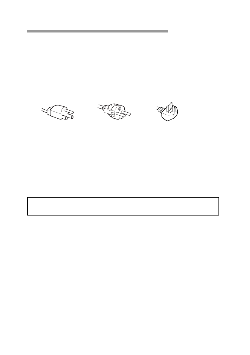
Warning on Power Connection
• Use the supplied power cord.
For the customers in U.S.A.
If you do not do this, this display will not conform to mandatory FCC
standards.
For the customers in UK.
If you use the display in the UK, please use the supplied UK cable
with the UK plug.
for 100 to 120 V AC for 220 to 240 V AC for 240 V AC only
• Before disconnecting the power cord, wait at least 30 seconds after
turning off the power switch to discharge static electricity from the
CRT display surface.
• After the power has been turned on, the CRT is demagnetized for
approximately 5 seconds. This generates a strong magnetic field
around the bezel which may affect the data stored on magnetic tape or
disks near the bezel. Place such magnetic recording equipment and
tapes/disks at a distance from this unit.
The socket-outlet shall be installed near the equipment and shall be
easily accessible.
8
Precautions
Functions of Controls
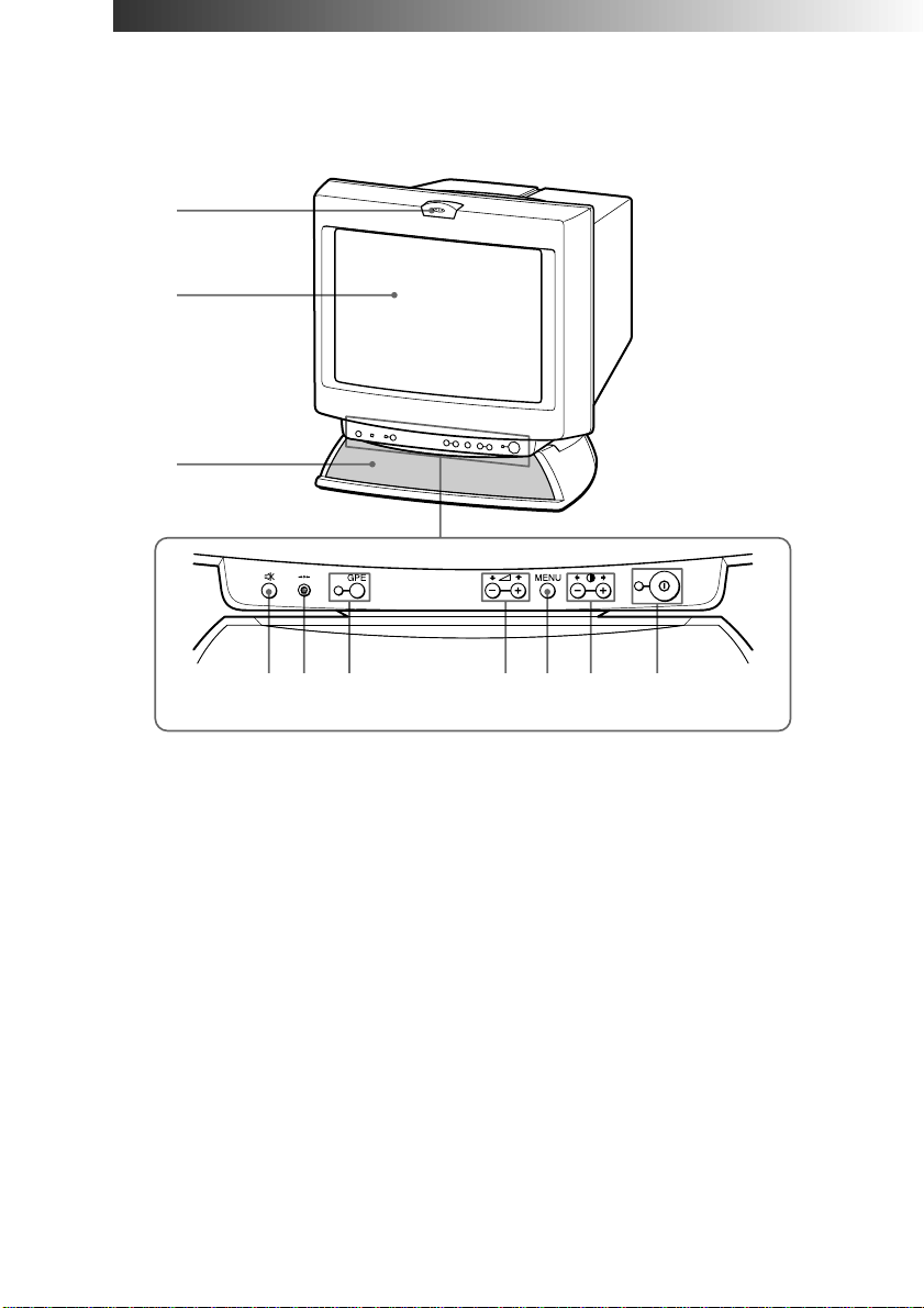
Front
1
2
3
45 6 7 8 9 !º
1
Microphone
Screen
2
Stereo speakers
3
¤ Mute button
4
? Reset switch
5
GPE button and
6
indicator
7
. Volume +/–
buttons
8
MENU button
9
> +/– Contrast
buttons
!º
U Power switch
and indicator
—
—
—
Mutes sound (page 20).
Resets adjustments to factory setting (page 31).
Sets GPE mode (page 32).
Adjust speaker volume (page 19). Use to select
items in an OSD.
Displays the OSD menu.
Adjust picture contrast (page 21). Use to adjust
items in an OSD.
Turns the display on and off.
Functions of Controls
9
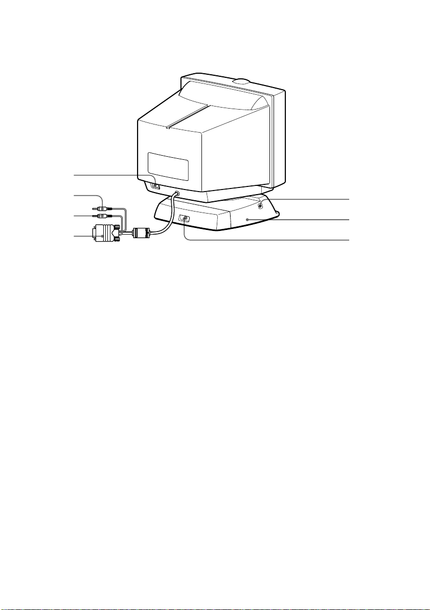
Rear
!¡
!™
!£
!¢
!¡
AC IN connector
!™
2 Audio plug (green)
h MIC plug (red)
!£
; Video signal cable
!¢
(blue)
2 Headphones jack
!∞
Tilt-Swivel
!§
Subwoofer output
!¶
jack
!∞
!§
!¶
Connect the supplied power cord (page 13).
Connect to the computer’s audio output
(page 12).
Connect to the computer’s microphone input
(page 12).
Connect to the computer’s video output
(page 12).
Connect standard mini-plug headphones (not
supplied). The speakers are turned off when
headphones are connected.
Adjusts the angle of the display (page 15).
Connect to a subwoofer’s input (not supplied).
Functions of Controls
10

Getting Started
Before using this display, please make sure that the following items are
included in your package:
• Multimedia computer display (1)
• Power cord (1)
• Warranty card (1)
• Operating instructions manual (1)
• Windows Monitor Information Disk and its instruction manual (1)
✎ Tip
This display will sync with any IBM or compatible system equipped with VGA1) or greater
graphics capability. Although this display will sync to other platforms running at horizontal
frequencies between 30 and 70 kHz, including Macintosh
cable adapter is required. Please consult Sony Technical Support for advice on which adapter is
suitable for your needs.
1) VGA is a trademark of IBM Corporation.
2) Macintosh is a trademark of Apple Computer Inc.
2)
and Power Macintosh systems, a
Continued to the next page ➔
Getting Started
11
AL
LINE OUT
USB
CONTR
LINE IN
MIC
MONITOR
PRINTER
2
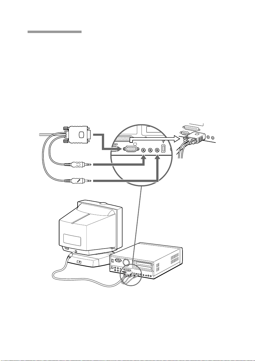
Installation
p Step 1: Connect the computer
With the computer switched off, connect the video signal cable to the
display (VGA) connector on your computer. If your computer supports
the DDC plug-and-play standard, this connection will enable DDC
communication between the display and the computer.
The video signal cable is combined with audio and microphone cables.
If your computer is equipped with sound capability, connect the audio
(green) and microphone (red) plugs to appropriate jacks located on your
computer.
Blue (to monitor
connector)
Fasten the
screw of the
Green (to LINE OUT
connector)
Red (to microphone
connector)
blue plug.
Computer
✔Note on handling the video signal cable
Do not touch the pins of the video signal cable.
12
Getting Started
 Loading...