

Sony CPD-2003GT Service Manual
CPD-2003GT
CPD-2003GT
SERVICE MANUAL
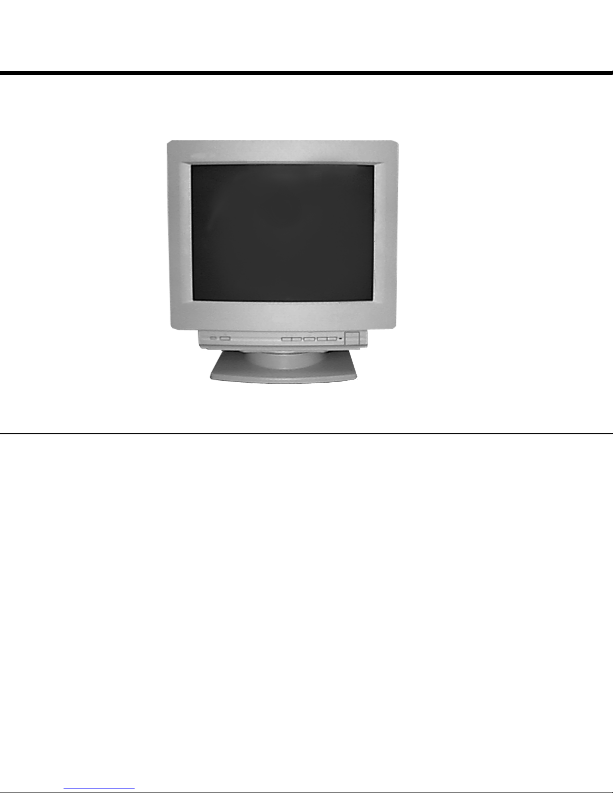
CPD-2003GT
US Model
Canadian Model
Chassis No. SCC-L07N-A
Picture tube
Viewable image size
Logical Resolution
Standard image area
SPECIFICATIONS
0.25 mm aperture grill pitch
17 inches measured diagonally
90-degree deflection
Approx. 327 x 243 mm (w/h)
7/8
5/8
x 9
x 9
inches)
1/4
inches)
(12
16.0" viewing image
Horizontal: Max. 1280 dots
Vertical: Max. 1024 lines
Approx. 312 x 234 mm (w/h)
3/8
(12
D-1H
Deflection frequency
AC input voltage / current
Dimensions
Mass
Design and specifications are subject to change without notice.
Horizontal: 30 to 85 KHz
Vertical: 50 to120 Hz
100 to 240 V, 50-60 Hz, 1.8 - 1.1 A
406 x 432 x 420 mm (w/h/d)
(16 x 17
Approx. 18.0 kg (39 lb 11 oz)
CHASSIS
1/8
5/8
x 16
inches)
COLOR COMPUTER DISPLAY
— 1 —
CPD-2003GT
(
µ
)
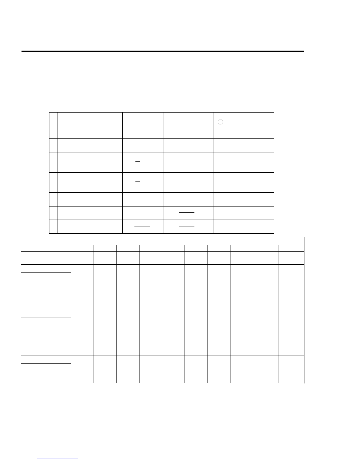
POWER SAVING FUNCTION
This monitor has three Power Saving modes.
By sensing the absence of a video signal from the
computer, it reduces power consumption as follows:
State Power Required Power Indicator
Consumption recovery time
1 Normal Operation
2 Standby (1st mode)
3 Suspend (2nd mode)
4 Active-off (3rd mode)
< 110W Green on
< 15W approx. 3 sec. Green and orange
< 15W approx. 3 sec. Green and orange
< 8W approx. 10 sec. Orange
5 Power-off 0W Off
6 Failure mode Orange flashing
NOTE:
If no video signal is input to the monitor, the
"NO INPUT SIGNAL" mesage appears. After
about 30 seconds, the Power Saving function
automatically puts the monitor into active-off
mode and the indicator lights up orange. Once
the monitor detects horizontal and vertical
sync signals, the monitor automatically resumes normal operation mode.
alternate
alternate
TIMING SPECIFICATION
MODE 12345678 9 10
Resolution (H x V) 640 x 480 720 X 400 640 X 480 800 x 600 800 x 600 1024 X 768 1024 x 768 1024 x 768 1280 X 1024 1280 x 1024
Dot Clock (MHz) 25.175 28.322 36.000 49.500 56.250 65.000 78.750 94.500 108.000 135.000
HORIZONTAL
Hor. Freq. (kHz) 31.469 31.469 43.269 46.875 53.674 48.363 60.023 68.677 63.981 79.976
H-Total 31.778 31.777 23.111 21.333 18.631 20.677 16.660 14.561 15.630 12.504
H-Blanking 6.356 6.355 5.333 5.172 4.409 4.923 3.657 3.725 3.778 3.022
H-Front Porch 0.636 0.636 1.556 0.323 0.569 0.369 0.203 0.508 0.444 0.119
H-Sync. 3.813 3.813 1.556 1.616 1.138 2.092 1.219 1.016 1.037 1.067
H-Back Porch 1.907 1.907 2.222 3.232 2.702 2.462 2.235 2.201 2.296 1.837
H-Active 25.422 25.422 17.778 16.162 14.222 15.754 13.003 10.836 11.852 9.481
sec
VERTICAL
Ver. Freq. (Hz) 59.940 70.087 85.008 75.000 85.061 60.004 75.029 84.997 60.020 75.025
V-Total 5 25 449 5 09 6 25 6 31 806 8 00 8 08 1066 1066
V-Blanking 4 5 49 2 9 25 3 1 3 8 32 4 0 4 2 4 2
V-Front Porch 1 0 12 111311 1 1
V-Sync. 22333633 3 3
V-Back Porch 3 3 3 5 2 5 2 1 2 7 2 9 2 8 3 6 3 8 3 8
V-Active 4 80 4 00 4 80 600 6 00 7 68 7 68 768 1024 1024
(lines)
SYNC.
Ext (H/V)/Polarity Yes -/- Yes -/+ Yes -/- Yes +/+ Yes +/+ Yes -/- Yes +/+ Yes +/+ Yes +/+ Yes +/+
Ext (CS)/Polarity No No No No No No No No No No
Int (G) No No No No No No No No No No
Int/Non Int Non Int Non Int Non Int Non Int Non Int Non Int Non Int Non Int Non Int Non Int
— 2 —
SAFETY CHECK-OUT
CPD-2003GT
After correcting the original service problem, perform
the following safety checks before releasing the set to the
customer:
1.Check the area of your repair for unsoldered or
poorly-soldered connections. Check the entire board
surface for solder splashes and bridges.
2.Check the interboard wiring to ensure that no wires
are “pinched” or contact high-wattage resistors.
3.Check that all control knobs, shields, covers, ground
straps, and mounting hardware have been replaced.
Be absolutely certain that you have replaced all the
insulators.
4.Look for unauthorized replacement parts,
particularly transistors, that were installed during
a previous repair. Point them out to the customer
and recommend their replacement.
5.Look for parts which, though functioning, show
obvious signs of deterioration. Point them out to
the customer and recommend their replacement.
6.Check the line cords for cracks and abrasion.
Recommend the replacement of any such line cord
to the customer.
7.Check the B+ and HV to see if they are specified
values. Make sure your instruments are accurate;
be suspicious of your HV meter if sets always have
low HV.
8.Check the antenna terminals, metal trim,
“metallized" knobs, screws, and all other exposed
metal parts for AC Leakage. Check leakage as
described below.
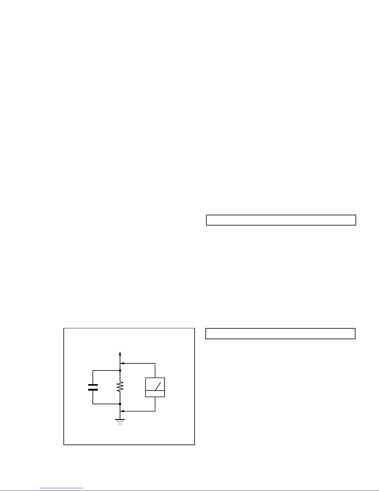
LEAKAGE TEST
The AC leakage from any exposed metal part to earth ground
and from all exposed metal parts to any exposed metal part having
a return to chassis, must not exceed 0.5 mA (500 microampere).
Leakage current can be measured by any one of three methods.
1.A commercial leakage tester, such as the Simpson 229 or
RCA WT-540A. Follow the manufacturers' instructions to
use these instructions.
2.A battery-operated AC milliammeter. The Data Precision
245 digital multimeter is suitable for this job.
3.Measuring the voltage drop across a resistor by means of
a VOM or battery-operated AC voltmeter. The "limit"
indication is 0.75 V, so analog meters must have an accurate
low voltage scale. The Simpson's 250 and Sanwa
SH-63Trd are examples of passive VOMs that are suitable.
Nearly all battery operated digital multimeters that have a
2V AC range are suitable. (See Fig. A)
WARNING!!WARNING!!
WARNING!!
WARNING!!WARNING!!
NEVER TURN ON THE POWER IN A CONDITION IN WHICH THE
DEGAUSS COIL HAS BEEN REMOVED.
SAFETY-RELATED COMPONENT WARNING!!
COMPONENTS IDENTIFIED BY SHADING AND MARK ¡ ON
THE SCHEMATIC DIAGRAMS, EXPLODED VIEWS AND IN THE
PARTS LIST ARE CRITICAL FOR SAFE OPERATION. REPLACE
THESE COMPONENTS WITH SONY PARTS WHOSE PART
NUMBERS APPEAR AS SHOWN IN THIS MANUAL OR IN
SUPPLEMENTS PUBLISHED BY SONY. CIRCUIT ADJUSTMENTS
THAT ARE CRITICAL FOR SAFE OPERATION ARE IDENTIFIED
IN THIS MANUAL. FOLLOW THESE PROCEDURES WHENEVER
CRITICAL COMPONENTS ARE REPLACED OR IMPROPER
OPERATION IS SUSPECTED.
To Exposed Metal
Parts on Set
0.15 µF
1.5 k
W
Earth Ground
AC
Voltmeter
(0.75 V)
AVERTISSEMENT!!
NE JAMAIS METTRE SOUS TENSION QUAND LA BOBINE DE
DEMAGNETISATION EST ENLEVEE.
ATTENTION AUX COMPOSANTS RELATIFS A LA
SECURITE!!
LES COMPOSANTS IDENTIFIES PAR UNE TRAME ET PAR UNE
MARQUE ¡ SUR LES SCHEMAS DE PRINCIPE, LES VUES
EXPLOSEES ET LES LISTES DE PIECES SONT D'UNE
IMPORTANCE CRITIQUE POUR LA SECURITE DU
FONCTIONNEMENT. NE LES REMPLACER QUE PAR DES
COMPOSANTS SONY DONT LE NUMERO DE PIECE EST
INDIQUE DANS LE PRESENT MANUEL OU DANS DES SUPPLEMENTS PUBLIES PAR SONY. LES REGLAGES DE CIRCUIT
DONT L'IMPORTANCE EST CRITIQUE POUR LA
SECURITE DU FONCTIONNEMENT SONT IDENTIFIES DANS
LE PRESENT MANUEL. SUIVRE CES PROCEDURES LORS DE
CHAQUE REMPLACEMENT DE COMPOSANTS CRITIQUES, OU
LORSQU'UN MAUVAIS FONTIONNEMENT SUSPECTE
— 3 —
.

CPD-2003GT
TABLE OF CONTENTS
Section Title Page
1. GENERAL ................................................................................... 5
2. DISASSEMBLY
2-1. Cabinet Removal ............................................................10
2-2. Service Position .............................................................. 10
2-3. D and A Board Removal................................................ 10
2-4. Picture Tube Removal ................................................... 11
3. SAFETY RELA TED ADJUSTMENT................................. 12
4. ADJUSTMENTS ........................................................................13
5. DIAGRAMS
5-1. Block Diagram ................................................................15
5-2. Circuit Boards Location ................................................. 18
5-3. Schematic Diagrams and Printed Wiring Boards ...... 18
1. D Board - Schematic Diagram .................................19
2. A Board - Schematic Diagram ................................. 23
5-4. Semiconductors ..............................................................27
6. EXPLODED VIEWS
6-1. Chassis ............................................................................ 29
6-2. Packing Materials .......................................................... 30
7. ELECTRICAL PARTS LIST ................................................ 31
— 4 —
— 5 —
CPD-2003GT
SECTION 1
GENERAL
The instructions given here are partial abstracts from the Operating Instruction
Manual. The page numbers shown reflect those of the Operating Instruction Manual.
4
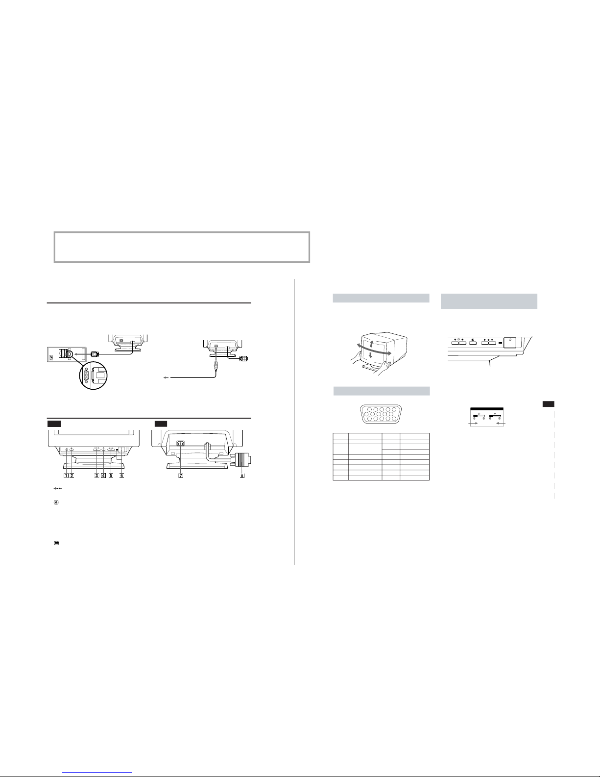
Parts and Controls
Rear
1 (RESET) button (pages 6 and 9)
Resets the adjustments to the factory settings.
2 Video Enhancement Mode button
(page 10)
Selects the Video Enhancement Mode.
3 ¨ (BRIGHTNESS) ./> buttons (page 5)
Adjust the picture brightness.
Operate as the ./> buttons when adjusting other
items.
4 (MENU) button (pages 6 and 10)
Displays the MENU OSD.
5 > (CONTRAST) ?// buttons (page 5)
Adjust the contrast.
Operate as the ?// buttons when adjusting other
items.
6 u (POWER) switch and indicator (page 11)
Turns the monitor on and off.
The indicator lights up green when the monitor is on,
and lights up green and orange when the monitor is in
Power Saving mode.
7 AC IN connector
Provides AC power to the monitor.
8 Video input connector (HD15)
Inputs RGB video signals and SYNC signals
Front
Getting Started
Step 2 Make sure the monitor is switched off and attach the
power cord to the monitor. Then, attach the other end
of the power cord to a power outlet.
Step 3 Switch on the monitor and computer.
Step 4 Adjust the user controls according to your personal
preference.
Installation is complete.
Power cord
to a power outlet
Setup
Connect the monitor to your computer system.
This monitor will sync to platforms running at horizontal frequencies between 30 and 85 kHz.
Step 1 Make sure the computer system is switched off and
attach the video signal cable to the video output of the
computer.
to the video output
Computer
5
Getting Started
ES
F
EN
D
I
RF
PL
SI
H
CZ
Video Connector
Pin No. Signal
1 Red
2 Green (Composite
Sync on Green)
3 Blue
4 Ground
5 CPU Sense
6 Red Ground
7 Green Ground
Pin No. Signal
8 Blue Ground
9 Not used
(no pin)
10 Ground
11 Ground
12 SDA
(serial data)
13 Horizontal Sync
14 Vertical Sync
15 SCL
(serial clock)
Use of the Tilt/Swivel
With the tilt/swivel, you can adjust this monitor to any desired
angle within 180° horizontally and 20° vertically.
To turn the monitor vertically and horizontally, hold it at the
bottom with both hands as shown below.
15°
90°
90°
5°
6
11 12 13 14 15
12345
78910
Getting Started
Customizing Your Monitor
Adjusting the Picture Brightness and
Contrast
1
Press the ¨ (BRIGHTNESS) ./> or
> (CONTRAST) ?// buttons.
The BRIGHTNESS/CONTRAST OSD appears.
2
To adjust the brightness
Press the ¨ (BRIGHTNESS) ./> buttons.
To adjust the contrast
Press the > (CONTRAST) ?// buttons.
Horizontal
frequency
Vertical
frequency
BRIGHTNESS/CONTRAST
26 26
60.0kHz/ 85Hz
— 6 —
CPD-2003GT
6
MENU
EXIT
CENTER
SIZE
GEOM
COLOR
LANG
ZOOM
SCREEN
OPTION
OK
MENU
ENGLISH
FRANÇAIS
DEUTSCH
ESPAÑOL
LANGUAGE
SIZE
26
73
CENTER
26
73
ZOOM
73V
66H
ROTATION
GEOMETRY
26
9300K
5000K
COLOR
MANUAL DEGAUSS
OPTION
ON
H CONVERGENCE
SCREEN
26
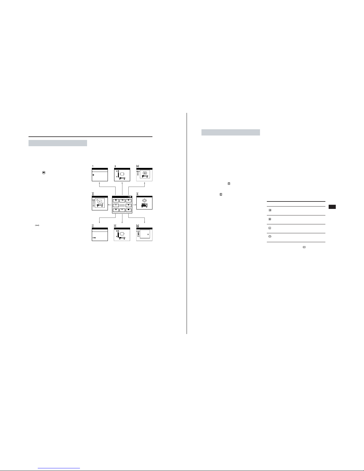
The OSD (On-screen Display) System
Introducing the OSD System
You can adjust most of the monitor’s settings using the OSDs
(On-screen Display). All of the OSDs numbered in this
illustration are described on the following pages in order. You
can access any of these OSDs from the MENU OSD. To adjust
monitor settings using the OSDs, follow the steps below:
Basic controls:
• Use the
(MENU) button to display the MENU OSD
and to select menu items.
• Use the ¨ (BRIGHTNESS) ./> and > (CONTRAST)
?// buttons to highlight menu items and to adjust
settings.
To adjust the monitor settings:
1 Press the MENU button to display the MENU OSD.
2 Highlight the desired OSD using the BRIGHTNESS and
CONTRAST buttons and press the MENU button again.
3 If necessary, use the BRIGHTNESS buttons to select a
specific item.
4 Adjust the monitor setting using the BRIGHTNESS and
CONTRAST buttons.
• To reset the current item to its original setting, press the
(RESET) button while the item’s adjustment OSD
is displayed.
5 When you finish adjusting the setting, press the MENU
button to return to the MENU OSD.
Press the MENU button twice to return to normal viewing.
• Resetting: If you press the RESET button while an OSD is
displayed, only the current adjustment item is reset. For
additional information on using the reset function, see
the “Resetting the Adjustments” section on page 9.
• The OSD automatically disappears after 30 seconds.
COLOR CENTER
SCREEN
GEOMETRY ZOOM
LANGUAGE OPTIONSIZE
Customizing Your Monitor
7
Getting Started
ES
F
EN
D
I
RF
PL
SI
H
CZ
1 Using the COLOR OSD
You can adjust the monitor’s color temperature using the
COLOR OSD. For example, you can adjust the monitor to
match the colors of a printed picture.
You can adjust the color temperature from 9300K (blue-white)
to 5000K (warm red).
This setting is stored in memory for all input signals.
1 Press the MENU button to display the MENU OSD.
2 Highlight the COLOR OSD using the BRIGHTNESS and
CONTRAST buttons and press the MENU button again.
3 Press the ¨ (BRIGHTNESS) ./> buttons to select either the
9300K, 5000K or variable
option.
• The 9300K and 5000K options display accurate preset
color temperatures.
• The variable
option allows you to adjust the monitor
using the full range of color temperatures. Adjust to the
desired color temperature using the CONTRAST
buttons.
4 Press the MENU button once to return to the MENU OSD,
or press it twice to return to normal viewing.
Note
If you are using one of the Video Enhancement Modes, you can
only adjust the color temperature from 11,000K to 9,300K.
For more information on Video Enhancement Mode, refer to
page 10.
2 Using the CENTER OSD
You can adjust the picture centering using the CENTER OSD.
This setting is stored in memory for the current input signal.
1 Press the MENU button to display the MENU OSD.
2 Highlight the CENTER OSD using the BRIGHTNESS and
CONTRAST buttons and press the MENU button again.
3 To adjust vertical centering, press the ¨ (BRIGHTNESS)
./> buttons.
4 To adjust horizontal centering, press the > (CONTRAST)
?// buttons.
5 Press the MENU button once to return to the MENU OSD,
or press it twice to return to normal viewing.
3 Using the SCREEN OSD
You can adjust the convergence of the picture and cancel the
picture’s moire using the SCREEN OSD.
Convergence is the alignment of the Red, Green and Blue
electron beams on the screen. When convergence is not aligned,
red or blue shadows may be noticeable (especially with text)
which can affect the clarity or focus of the image.
Moire is a wavy or elliptical pattern which may appear on the
screen. The moire cancel adjustment is provided to eliminate
moire.
This setting is stored in memory for all input signals.
1 Press the MENU button to display the MENU OSD.
2 Highlight the SCREEN OSD using the BRIGHTNESS and
CONTRAST buttons and press the MENU button again.
3 Press the ¨ (BRIGHTNESS) ./> buttons to select the
desired adjustment item.
4 Press the > (CONTRAST) ?// buttons to adjust the item.
5 Press the MENU button once to return to the MENU OSD,
or press it twice to return to normal viewing.
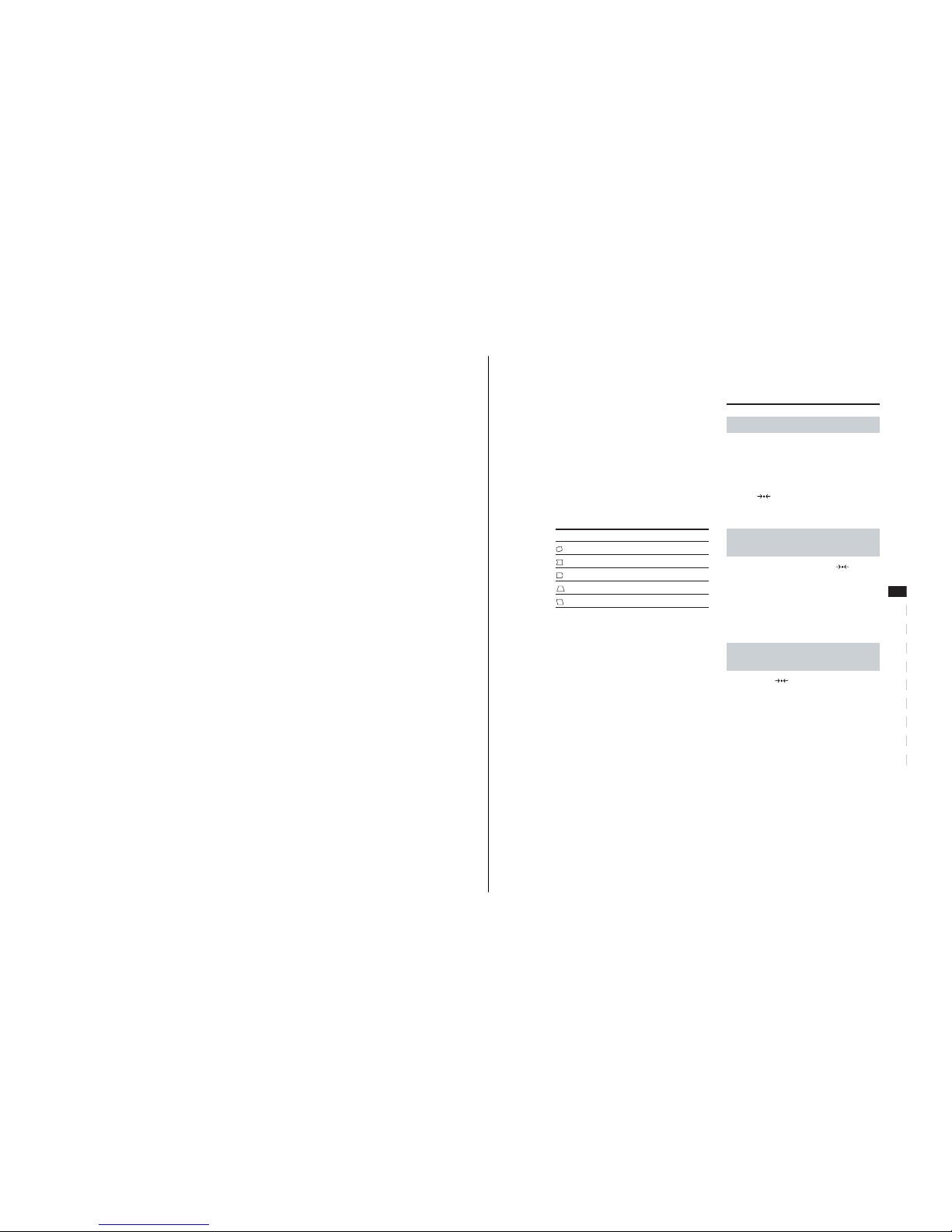
Adjusting the Settings
To
adjust the horizontal convergence
adjust the vertical convergence
eliminate elliptical or wavy lines on
the screen
adjust the degree of moire
cancellation
* CANCEL MOIRE must be “ON” for “
(MOIRE ADJUST)” to
appear on the screen. MOIRE ADJUST operates only for
Horizontal input signals greater than 43 kHz.
Select
H CONVERGENCE
V CONVERGENCE
CANCEL MOIRE
*
MOIRE ADJUST
Customizing Your Monitor
— 7 —
CPD-2003GT
8
Customizing Your Monitor
7 Using the LANGUAGE OSD
You can set the OSD language to English, German, French,
Spanish or Japanese using the LANGUAGE OSD.
To reset to English, press the RESET button while the
LANGUAGE OSD is displayed.
1 Press the MENU button to display the MENU OSD.
2 Highlight the LANGUAGE OSD using the BRIGHTNESS
and CONTRAST buttons and press the MENU button again.
3 Press the ¨ (BRIGHTNESS) ./> buttons to select the
desired language.
4 Press the MENU button once to return to the MENU OSD,
or press it twice to return to normal viewing.
5 Using the OPTION OSD
You can manually degauss (demagnetize) the CRT, move the
OSD position and lock the user controls using the OPTION
OSD.
1 Press the MENU button to display the MENU OSD.
2 Highlight the OPTION OSD using the BRIGHTNESS and
CONTRAST buttons and press the MENU button again.
3 Press the ¨ (BRIGHTNESS) ./> buttons to select the
desired adjustment item.
4 Press the > (CONTRAST) ?// buttons to activate the
manual degauss, move the OSD position or lock the user
controls.
5 Press the MENU button once to return to the MENU OSD,
or press it twice to return to normal viewing.
Degauss: If a second degauss cycle is needed, allow a minimum
interval of 20 minutes for the best result.
OSD Position Change: To change the OSD position, press the
¨ (BRIGHTNESS) ./> buttons to select the direction
(horizontal or vertical), then press the > (CONTRAST)
?// buttons to move the OSD in the selected direction.
User Control Lock: Once you select “ON” to lock the user
controls, you cannot select any item except “EXIT” and
“OPTION” in the MENU OSD. If you try to access any other
OSD, the H mark appears on the screen.
To cancel the Control Lock: Repeat the above procedure and
set Control Lock to “OFF.”
6 Using the SIZE OSD
You can adjust the picture size using the SIZE OSD.
This setting is stored in memory for the current input signal.
1 Press the MENU button to display the MENU OSD.
2 Highlight the SIZE OSD using the BRIGHTNESS and
CONTRAST buttons and press the MENU button again.
3 To adjust the vertical size press the ¨ (BRIGHTNESS) ./>
buttons.
4 To adjust the horizontal size press the > (CONTRAST)
?// buttons.
5 Press the MENU button once to return to the MENU OSD,
or press it twice to return to normal viewing.
4 Using the ZOOM OSD
You can enlarge or reduce the picture size using the ZOOM
OSD.
This setting is stored in memory for the current input signal.
1 Press the MENU button to display the MENU OSD.
2 Highlight the ZOOM OSD using the BRIGHTNESS and
CONTRAST buttons and press the MENU button again.
3 Press the > (CONTRAST) ?// buttons to enlarge or
reduce the picture size.
4 Press the MENU button once to return to the MENU OSD,
or press it twice to return to normal viewing.
Note
You can enlarge or reduce the picture size until either the
horizontal or vertical size reaches its maximum or minimum
value.
9
Getting Started
ES
F
EN
D
I
RF
PL
SI
H
CZ
Resetting the Adjustments
Resetting all of the adjustments for
the current input signal
While there is no OSD displayed, press the
(RESET)
button.
All of the adjustments for the current input signal are reset to
the factory settings.
Adjustments not affected by changes in the input signal (such
as OSD language, OSD position and the Control Lock function)
are not reset to the factory settings.
Resetting all of the adjustments for
all input signals
Press and hold the (RESET) button for more than two
seconds.
All of the adjustments, including the brightness and contrast,
are reset to the factory settings.
Resetting a specific adjustment:
1 Press the MENU button to display the MENU OSD
2 Highlight the OSD containing the adjustment you want to
reset using the BRIGHTNESS and CONTRAST buttons and
press the MENU button again.
3 Press the ¨ (BRIGHTNESS) ./> buttons to select the
adjustment you want to reset.
4 Press the
(RESET) button to reset this specific
adjustment.
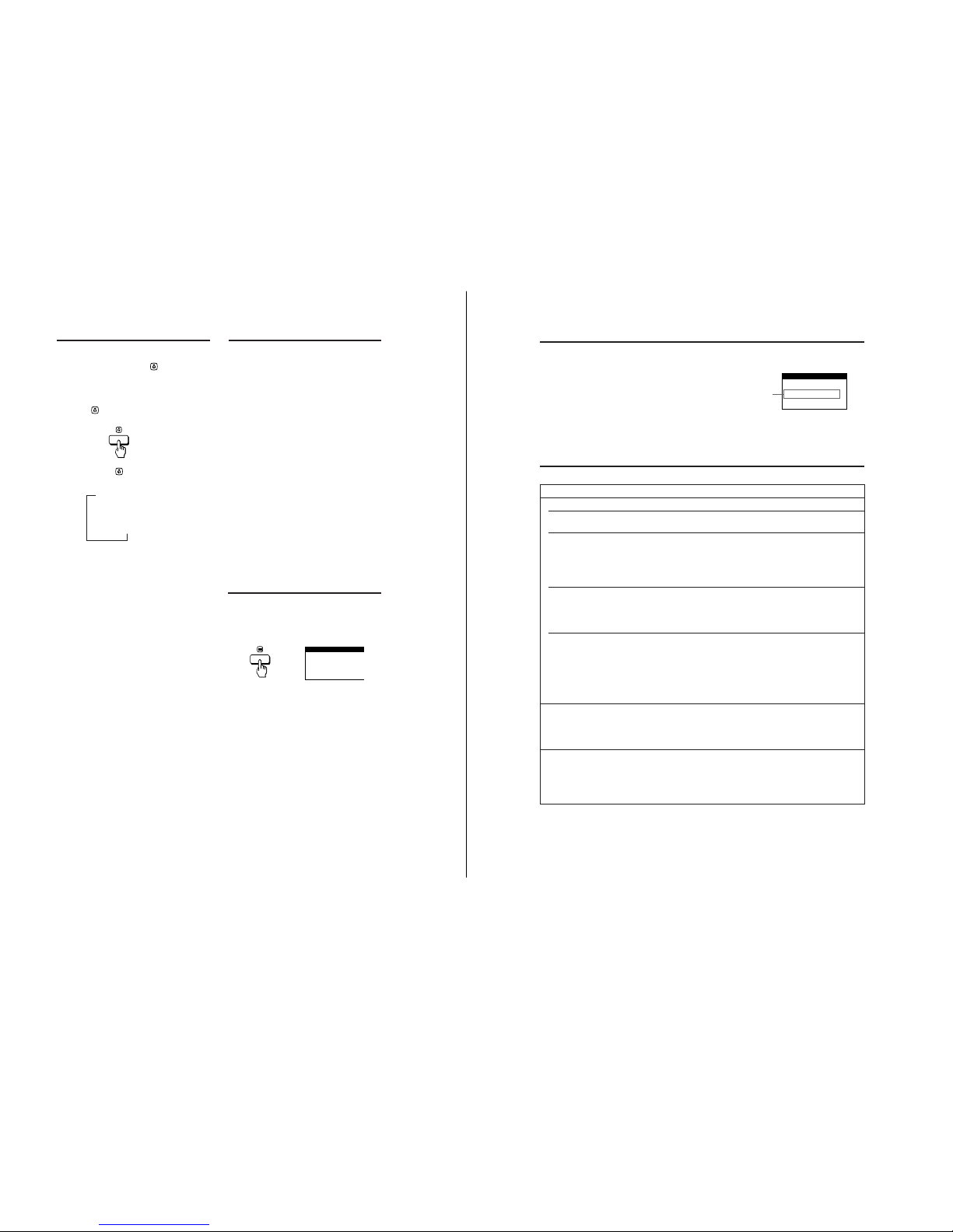
8 Using the GEOMETRY OSD
You can adjust the picture’s geometry using the GEOMETRY
OSD.
This setting is stored in memory for the current input signal.
1 Press the MENU button to display the MENU OSD.
2 Highlight the GEOMETRY OSD using the BRIGHTNESS
and CONTRAST buttons and press the MENU button again.
3 Press the ¨ (BRIGHTNESS) ./> buttons to select the
desired geometry adjustment.
4 Press the > (CONTRAST) ?// buttons to adjust the
geometry.
5 Press the MENU button once to return to the MENU OSD,
or press it twice to return to normal viewing.
Select
ROTATION
PINCUSHION
PIN BALANCE
KEYSTONE
KEY BALANCE
To
adjust the picture rotation
adjust the picture sides
adjust the picture side balance
adjust the trapezoidal distortion
adjust the picture shape balance
Customizing Your Monitor
— 8 —
CPD-2003GT
10
Monitor Information
You can display the model name, serial number and year of
manufacture using the INFORMATION OSD.
Press and hold the MENU button for 5 seconds.
The INFORMATION OSD appears.
The INFORMATION OSD includes the model name, serial
number and year of manufacture.
The OSD automatically disappears after about 30 seconds.
INFORMATION
SER NO : 1234567
MODEL : CPD-2003GT
MANUFACTURED
: 1998
Technical Features
Specifications
Picture tube 0.25 mm aperture grill pitch,
17 inches measured diagonally,
90 degree deflection
Viewable image size Approx. 327 × 243 mm (w/h)
(12
7
/8 × 9 5/8 in.)
16.0” viewing image
Resolution
Horizontal Max. 1280 dots
Vertical Max. 1024 lines
Display picture size Approx. 312 × 234 mm (w/h)
(12
3
/8 × 9 1/
4
in.)
Deflection frequency
Horizontal 30 to 85 kHz
Vertical 50 to 120 Hz
AC input voltage/current
100 to 120 V, 50/60 Hz, 1.8 A
220 to 240 V, 50/60 Hz, 1 A
Dimensions 406 × 432 × 420 mm (w/h/d)
(16 × 17
1
/8 × 16 5/8 in.)
Mass Approx. 18 kg (39 lb 11 oz)
Design and specifications are subject to change without notice.
Video Enhancement Mode
You can automatically change the characteristics of the picture
to match the way you use your monitor with the Video
Enhancement Mode. Simply press this
button to cycle
through the three modes.
1
Turn on the monitor and computer.
2
Press this button to set the mode.
Each time you press the
Video Enhancement Mode button,
the mode changes and appears on the screen as follows.
The STANDARD MODE is ideal for spreadsheets, word
processing, and other text oriented applications.
The PRESENTATION MODE is useful for presentation
programs that require vivid colors.
The GRAPHICS/VIDEO MODE gives movies and games
enhanced visual appeal by increasing the sharpness and
brightness.
The selected mode indication appears on the screen for about
three seconds.
If the screen appears too white, adjust the color temperature
(see “Using the COLOR OSD” on page 7).
Note
The PRESENTATION MODE and GRAPHICS/VIDEO MODE may
produce ghost images when displaying text oriented applications.
These modes change the brightness of the picture dynamically
according to changes in moving pictures. If ghost images appear,
set the Video Enhancement Mode to STANDARD MODE.
Customizing Your Monitor
n
nn
STANDARD MODE
PRESENTATION MODE
GRAPHICS/VIDEO MODE
12
Additional Information
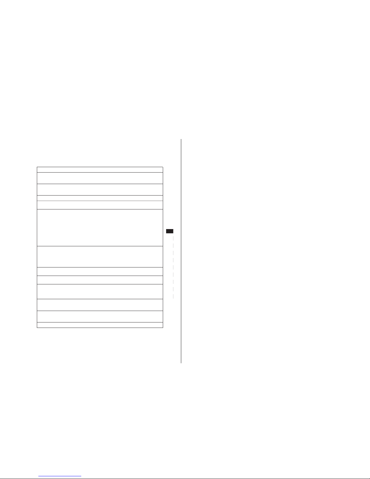
Troubleshooting
This section may help you isolate the cause of a problem and as a result, eliminate the need to contact technical support.
Symptom Check these items
No picture
If the u indicator is not lit
If the “NO INPUT SIGNAL”
message appears on the screen, or
if the u indicator is either orange
or alternating between green and
orange
If the “OUT OF SCAN RANGE”
message appears on the screen
If no message is displayed and
the u indicator is green or
flashing orange
Picture is scrambled
Color is not uniform
Warning Messages
If there is something wrong with the input signal, one of the following messages appears.
Input signal condition
• Make sure the power cord is properly connected.
• Make sure the u (POWER) switch is in the “ON” position.
• Try pressing any key on the computer keyboard.
• Make sure your computer is turned on.
• Make sure the video signal cable is properly connected and all plugs are firmly seated in
their sockets.
• Make sure none of the HD15 video input connector pins are bent or pushed in.
• Make sure the video board is completely seated in the proper bus slot.
• Make sure the video frequency range is within that specified for the monitor.
Horizontal: 30 – 85 kHz
Vertical: 50 – 120 Hz
Refer to your computer system’s instruction manual to adjust the video frequency range.
• If you are using a video signal cable adapter, make sure it is the correct type.
• Run the SELF TEST function:
1. Turn off the monitor and disconnect the video cable from the computer.
2. Turn on the monitor and wait five seconds. The “NO INPUT SIGNAL” message
should appear with a color bar pattern. The message and pattern are
displayed for 30 seconds.
If the monitor displays White, Red, Green and Blue colors, the monitor is
functioning properly.
• Make sure none of the HD15 video input connector pins are bent or pushed in.
• Check your video board manual for the proper monitor setting.
• Check this manual and make sure the monitor supports the graphics mode and the
frequency at which you are trying to operate. Even if the frequency is within the proper
range, some video boards may have a sync pulse that is too narrow for the monitor to
sync correctly.
• Degauss the monitor (page 8).
If you place equipment which generates a magnetic field, such as a loudspeaker, near the
monitor, or you change the direction of the monitor, the color may not be uniform.
The degauss function demagnetizes the metal frame of the CRT to obtain a neutral field
for uniform color reproduction. If a second degauss cycle is needed, allow a minimum
interval of 20 minutes for the best result.
INFORMATION
OUT OF SCAN RANGE
The input signal condition
“OUT OF SCAN RANGE” indicates that the input signal
is not supported by the monitor’s specifications.
“NO INPUT SIGNAL” indicates that no signal is input.
The message disappears after about 30 seconds.
To solve these problems, see the “Troubleshooting” section
below.
— 9 —
CPD-2003GT
13
Getting Started
ES
F
EN
D
I
RF
PL
SI
H
CZ
Symptom Check these items
You cannot adjust the monitor
with the buttons on the front
panel
Screen image is not centered or
sized properly
Edges of the image are curved
White lines show red or blue
shadows at edges
Picture is fuzzy
Picture bounces or has wavy
oscillations
Picture is flickering
Picture appears to be
ghosting
Wavy or elliptical (moire) pattern
is visible
Two fine horizontal lines (wires)
are visible
Hum is heard right after the
power is turned on
White does not look white
• If the Control Lock function is set to “ON,” set it to “OFF” using the OPTION OSD (page 8).
• Adjust the size (page 8) or centering (page 7).
• Some video modes do not fill the screen to the edges. This problem tends to occur with
certain video boards.
• Adjust the geometry (page 9).
• Adjust the convergence using the SCREEN OSD (page 7).
• Adjust the contrast and brightness (page 5).
• Degauss the monitor using the OPTION OSD (page 8).
If you place equipment which generates a magnetic field, such as a loudspeaker, near the
monitor, or you change the direction of the monitor, the color may not be uniform.
The degauss function demagnetizes the metal frame of the CRT to obtain a neutral field for
uniform color reproduction. If a second degauss cycle is needed, allow a minimum interval
of 20 minutes for the best result.
• If red or blue shadows appear along the edges of images, adjust the convergence using the
SCREEN OSD (page 7).
• If the moire is cancelled, the picture may become fuzzy. Decrease the moire cancellation
effect using the SCREEN OSD (page 7).
• Isolate and eliminate any potential sources of electric or magnetic fields. Common causes
for this symptom are electric fans, fluorescent lighting and laser printers.
• If you have another monitor close to this monitor, increase the distance between them to
reduce the interference.
• Try plugging the monitor into a different AC outlet, preferably on a different circuit.
• Try using the monitor with a different computer in a different room.
• Refer to your computer system’s manual and change your display refresh rate settings so
they match the monitor’s capabilities.
• Eliminate the use of video cable extensions and/or video switch boxes. Excessive cable
length or a weak connection can produce this symptom.
• Cancel the moire using the SCREEN OSD (page 7).
The moire may be modified depending on the connected computer.
• Due to the relationship between resolution, monitor dot pitch and the pitch of some image
patterns, certain screen backgrounds sometimes show moire. Change your desktop pattern.
• These wires stabilize the vertically striped aperture grille (page 11). This aperture grille
allows more light to pass through to the screen giving the Trinitron CRT more color and
brightness.
• When the power is turned on, the auto-degauss cycle is activated. While the auto-degauss
cycle is activated, a hum may be heard. The same hum is heard when the monitor is
manually degaussed. This is not a malfunction.
• Adjust the color temperature using the COLOR OSD (page 7).
Additional Information
CPD-2003GT
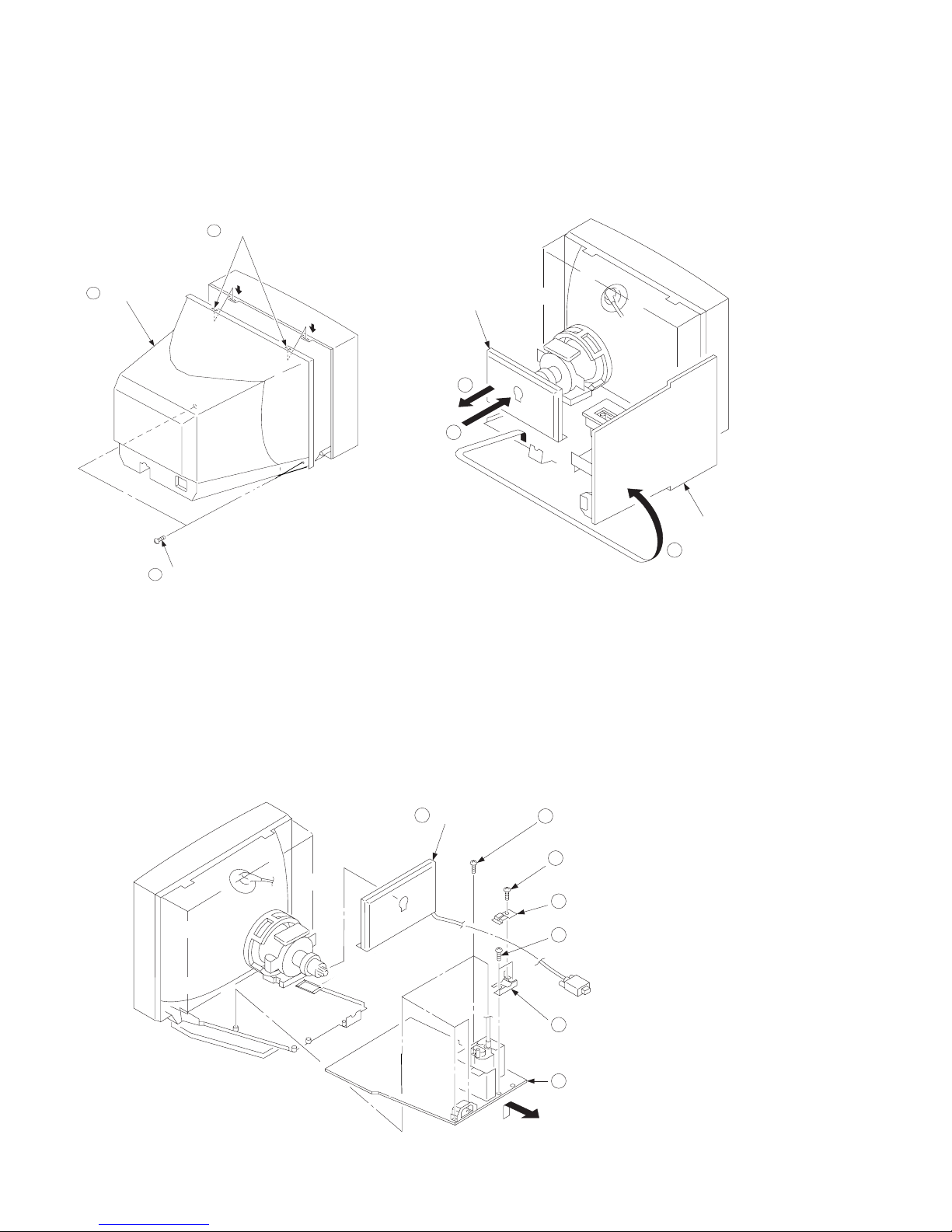
SECTION 2
DISASSEMBLY
2-1. CABINET REMOVAL
Two claws
3
Cabinet
4
Two screws
1
(BVTP 4 x 16)
PUSH
2-2. SERVICE POSITION
A board
PUSH
1
3
2
Two audio jacks**
**Caution: To avoid breakage, gently pull
sides of cabinet out and over the audio
jacks when removing cabinet from
chassis.
D board
2
2-3. D and A BOARD REMOVAL
A board
2
J board
— 10 —
1
3
Five screws
(BVTP 3 x 12)
4
One screw
(BVTT 4 x 8)
5
Cable stopper
6
Two screws
(BVTP 3 x 12)
7
Cable bracket
8
D board
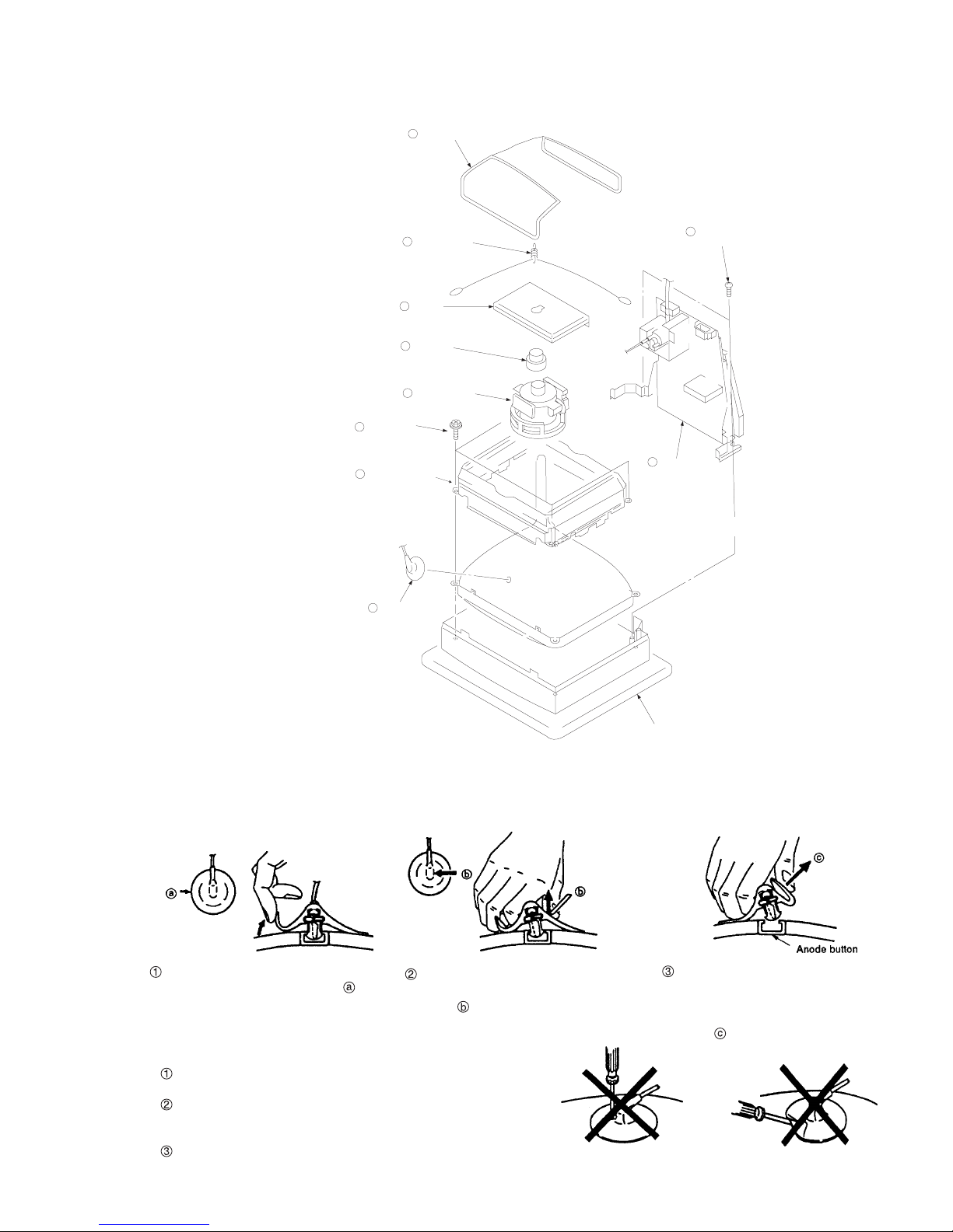
CPD-2003GT
2-4. PICTURE TUBE REMOVAL
3
Four screws
(Tapping screw 5)
Picture tube shield
2
8
Demagnetization coil
7
Tension spring
6
A board
5
Neck assy
4
Deflection yoke
9
Two screws
10
Stand assy
(D board)
(BVTP 4 x 16)
1
Anode cap
Cushion
REMOVAL OF THE ANODE-CAP
NOTE: Short circuit the anode of the picture tube and the anode cap to the metal chassis, CRT shield or carbon painted on the CRT, after
removing the anode.
REMOVAL PROCEDURES
Turn up one side of the rubber cap in
the direction indicated by arrow .
Use your thumb to pull the rubber cap
firmly in the direction indicated by
arrow .
HOW TO HANDLE AN ANODE-CAP
Do not use sharp objects which may cause damage to the surface
of the anode-cap.
Do not squeeze the rubber covering too hard to avoid damaging
the anode-cap. A material fitting called a shatter-hook terminal is
built into the rubber.
Do not force turn the foot of the rubber cover. This may cause the
shatter-hook terminal to protrude and damage the rubber.
When one side of the rubber cap sepa-
rates from the anode button, the anodecap can be removed by turning the rubber cap and pulling it in the direction of
arrow .
— 11 —
 Loading...