

Sony CNA-1 Operation Manual

CAMERA CONTROL NETWORK ADAPTOR
CNA-1
OPERATION MANUAL
[English]
1st Edition (Revised 1)

Table of Contents
Overview ...............................................................................3
Features ..........................................................................3
Examples of system configurations..................................4
Supported devices ..........................................................8
Location and function of parts ............................................8
Front panel ......................................................................8
Rear panel .....................................................................10
Starting and stopping the CNA-1 ......................................11
Menu operation ...................................................................11
Menu operation from a web browser .............................11
Menu configuration ........................................................12
Transport Converting Function Setting ...........................18
Transport converting with LAN ......................................18
Transport converting with RS232/422 ...........................23
HD Cutout Control Function Setting ................................24
About the USB controller ...............................................27
About the Gateway function ..............................................28
Specifications .....................................................................28
Notice Concerning Software Governed by the GNU GPL/
LGPL .............................................................................30
Table of Contents
2

Overview
Features
The CNA-1 is a network device for
expansion of the Sony camera network
system.
You can build a flexible camera network
system by using the Master device
function, CCA-LAN converting function,
or transport converting function. The
remote control function for the HD
Cutout function of the BPU (Baseband
Processor Unit) allows you to control
the HD Cutout frame by connecting the
USB controller to the CNA-1.
Also, the CNA-1 supports the Gateway
function. This extension allows you to
expand the camera network system by
adding a control panel or camera that
conforms to the simple protocol
provided from the CNA-1 to the camera
network system.
Transport converting
Using the two CNA-1s converts the
network protocol between a camera
and control panel, and allows you to
operate in a network environment with
many delays or operate using the
RS232/422 connection.
HD Cutout control function
You can control the HD Cutout frame of
the BPU with the USB controller that is
connected to the CNA-1 by connecting
the CNA-1 to the BPU via LAN.
Gateway function
The CNA-1 can convert the protocol of
the camera network system to a simpler
protocol.
This protocol allows you to develop
various applications easily and add
them to the camera network system.
Master device function
By working the CNA-1 as the master
device of the camera network system,
you can operate the MCS (multicamera system) without using the MSU.
CCA to LAN converting
If you connect the CNA-1 to the camera
network system via a LAN, and connect
the CCU or RCP device to the CNA-1
with the CCA cable, you can add the
CCU or RCP device easily to the
camera network system without
including them on the LAN.
Overview
3
Examples of system configurations
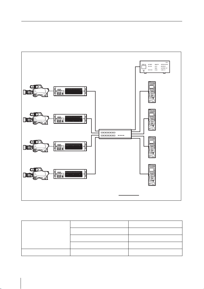
Example for the master device function
The CNA-1 works as the master device for the MCS.
CNA-1
Camera head
Camera head
Camera head
Camera head
CCU
MCS Mode: Client
CCU
MCS Mode: Client
CCU
MCS Mode: Client
CCU
MCS Mode: Client
Network hub
: LAN cable
CNA-1 setup
For details of the following setting items, see “Menu items” (page 12).
RCP
MCS Mode:
Client
RCP
MCS Mode:
Client
RCP
MCS Mode:
Client
RCP
MCS Mode:
Client
CNS Configuration CNS Mode MCS
Master Mode Enable
Master IP Address Variable
Target IP Address Variable
Gateway Configuration Gateway Mode Disable
Overview
4
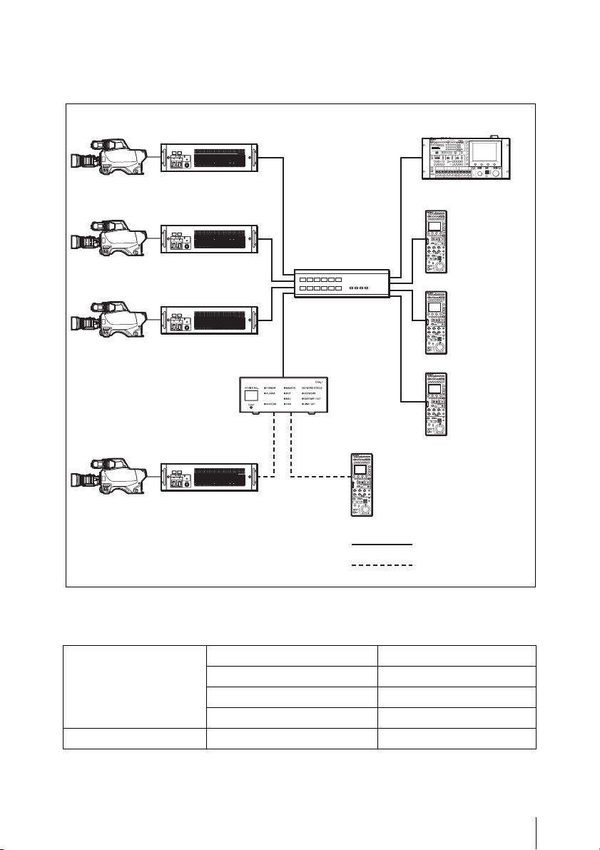
Example for CCA to LAN converting
This connection allows you to connect to the MCS with the CCA-5 interface .
Camera head
Camera head
Camera head
Camera head
CCU
MCS Mode: Client
CCU
MCS Mode: Client
CCU
MCS Mode: Client
CCU
CCU
CCA-5 I/F
Network hub
CNA-1
AUX
MSU
MCS Mode: Master
RCP
MCS Mode:
Client
RCP
MCS Mode:
Client
RCP
MCS Mode:
Client
RCP
CCA-5 I/F
: LAN cable
: CCA-5 cable
CNA-1 setup
For details of the following setting items, see “Menu items” (page 12).
CNS Configuration CNS Mode MCS
Master Mode Disable
Master IP Address Master MSU’s IP address
Target IP Address Variable
Gateway Configuration Gateway Mode Disable
Overview
5
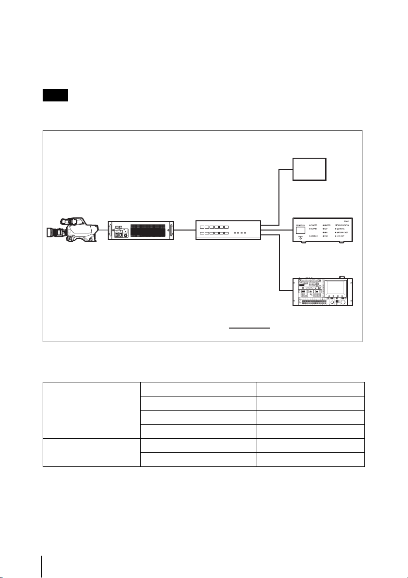
Example for the Gateway function
When controlling the Sony’s camera from the expansion control panel
This is the MCS connection via the LAN.
Note
The expansion control panel needs to be compatible with the simple protocol
provided from the CNA-1.
Expansion
control panel
Camera head
CCU
MCS Mode: Client
Network hub
CNA-1
MSU
MCS Mode:
Master
: LAN cable
CNA-1 setup
For details of the following setting items, see “Menu items” (page 12).
CNS Configuration CNS Mode MCS
Master Mode Disable
Master IP Address Master MSU’s IP address
Target IP Address Variable
Gateway Configuration Gateway Mode Enable
Emulation Mode RCP
6
Overview

When controlling a expansion camera from the Sony’s control panel (MSU,
RCP)
This is the MCS connection via the LAN.
Note
The expansion camera needs to be compatible with the simple protocol provided
from the CNA-1.
RCP
MCS Mode:
Client
Expansion camera
Network hub
: LAN cable
CNA-1 setup
For details of the following setting items, see “Menu items” (page 12).
CNS Configuration CNS Mode MCS
Master Mode Disable
Master IP Address Master MSU’s IP address
Target IP Address Variable
Gateway Configuration Gateway Mode Enable
Emulation Mode CAM
CNA-1
MSU
MCS Mode:
Master
Overview
7
Supported devices
This unit supports connection of the
following devices.
• HDC2000/2500
• HDCU2000/2500
• HDC1000(R)/1500(R)/3300(R)
• HDCU1000/1500/3300(R)
•HSC-300
• HSCU-300
• HDC-P1
• RCP-1500/1501/1530
• MSU-1000/1500
•HZC-CSM10
• BPU4000/8000
Note
The BPU4000/8000 is compatible with
the HD Cutout control function only.
Location and function of parts
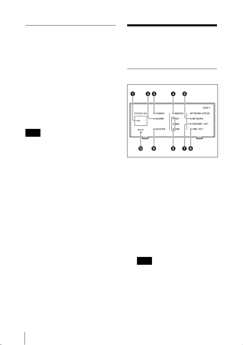
Front panel
Indicators
a DEVICE NO. indicator
Indicates the CNA-1’s device
number.
Location and function of parts
8
b ALARM indicator
Indicates the CNA-1’s operating
status.
Flashing: The CNA-1 is updating
the firmware, or cannot boot
properly.
Off: The CNA-1 is working
normally.
Note
If the ALARM indicator flashes
even though the CNA-1 is not
updating, immediately stop using
the CNA-1, and consult your Sony
Service Center.

c POWER indicator
Indicates the CNA-1’s power
status.
On: Power is being supplied.
Off: Power is not being supplied.
d MASTER indicator
Indicates the master mode status
of the CNA-1.
On: The CNA-1 is working in the
master mode.
Off: The CNA-1 is not working in
the master mode.
e NETWORK indicator
Indicates the network connection
status.
On: The CNA-1 is connected to the
network properly.
Flashing: If the CNS setting of the
CNA-1 is set to the MCS mode, the
CNA-1 is connected to the master
device properly, but there is no
destination (camera or CCU) or the
CNA-1 has failed to connect to it.
Off: If the CNA-1 is set to the MCS
mode, there is no master device or
the CNA-1 has failed to connect to
it. If the CNA-1 is set to the Bridge
mode, there is no destination
(CCU, RCP, or MSU) or the CNA-1
has failed to connect to it. If the
CNA-1 is set to legacy mode, the
CNA-1 has failed to connect to the
Gateway client device or the
CNA-1 has failed to connect to it.
f LINK / ACT indicator
Indicates the LAN communication
status of the CNA-1.
On: The CNA-1 is linked properly.
Flashing: The CNA-1 is linked
properly and data is being
exchanged.
Off: The CNA-1 is not linked.
g GATEWAY / ACT indicator
Indicates the communication status
between the Gateway client device
and the CNA-1.
On: The communication is
established.
Flashing: The communication is
established and data is being
exchanged.
Off: The communication is not
established.
h RCP, MSU, CAM indicator
Indicates the Gateway Emulation
mode status of the CNA-1. One of
the RCP, MSU, CAM indicators
turns on, or all indicators turn off.
On: The CNA-1 is working in the
Gateway Emulation mode
according to the indicator turned on
(RCP, MSU, or CAM Emulation
mode).
Off: The CNA-1 is not working in
the Gateway Emulation mode.
Note
The MSU indicator works only if the
HZC-MSCN1 optional software is
installed. This indicator usually
does not turn on.
i ACCESS indicator
Indicates the status of the internal
memory or connected USB mass
storage device.
On: The USB mass storage device
is connected.
Flashing: Read-write access is
being performed on the internal
memory or USB mass storage
device.
Off: Read-write access is not being
performed, or the USB mass
storage device is not connected.
Location and function of parts
9
Note
87
Do not disconnect a USB mass
storage device while the ACCESS
indicator is flashing.
Switch
c Network link status indicator
SPEED (green)
On: The CNA-1 is linked to a 100
Mbps network.
Off: The CNA-1 is linked to a 10
Mbps network, or a network cable
is not connected.
j RESET switch
Press and hold for 10 seconds to
reset the CNA-1 to the default
setting.
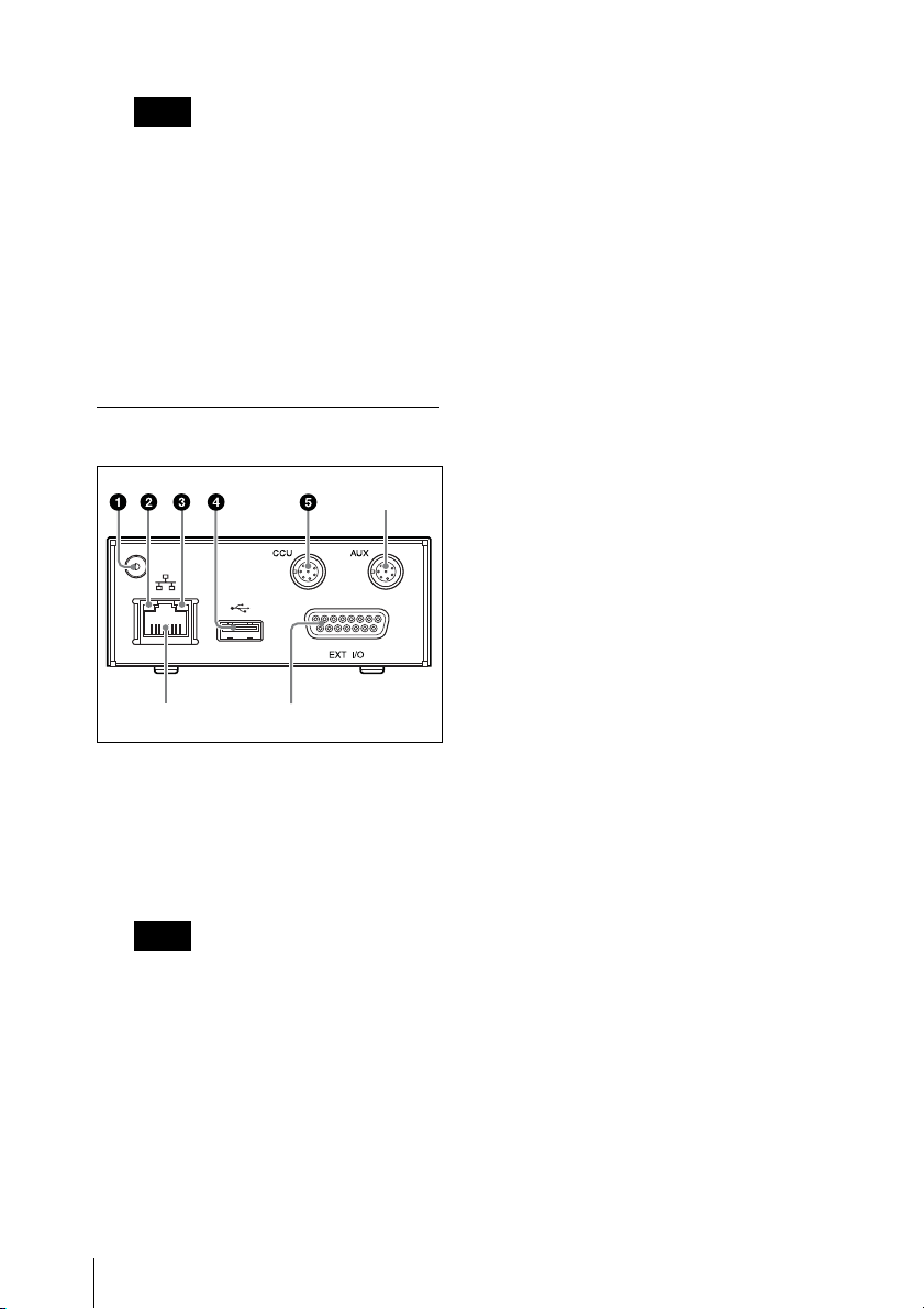
Rear panel
a Earth terminal
Connect to a safety ground.
To connect a ground terminal, use
the following screw.
• Thread Size: M3, Length (L): 6
(7-682-547-04 equivalent)
Note
When receiving power from the
PoE device, make sure to ground
the CNA-1 to earth.
6
d USB connector
Connect a USB controller for the
HD Cutout control function or a
USB flash drive for maintenance.
Do not connect a device other than
the above.
e CCU REMOTE connector (8-pin,
multi-connector, female
terminal)
Connect to the RCP/CNU
connector of the CCU.
f AUX REMOTE connector (8-pin,
multi-connector, female
terminal)
Preliminary connector.
g EXT I/O connector (D-sub 15-pin,
female terminal)
Connects the external interface.
h Network connector (RJ-45 8-pin)
Used for network connection.
Connect to the 100BASE-TX hub
with a network cable (shield type,
category 5 or higher). This
connecter can receive the power
from a power supply (PoE) device
that conforms to the IEEE802.3af
standard.
b Network link status indicator
LINK / ACT (orange)
On: The CNA-1 detects a valid link.
Flashing: The CNA-1 senses
transmit or receive activity.
Off: The CNA-1 could not detect a
valid link.
Location and function of parts
10
 Loading...