

Page 1

DISPLAY UNIT
CLX101ASA
ZRD-1
ZRD-2
DISPLAY CONTROLLER
CLF101AKA
ZRCT-100
Manual for Color Uniformity Alignment Software
1st Edition (Revised 2)
Page 2

!警告
このマニュアルは,サービス専用です。
お客様が,このマニュアルに記載された設置や保守,点検,修理などを行うと感電や火災,
人身事故につながることがあります。
危険をさけるため,サービストレーニングを受けた技術者のみご使用ください。
! WARNING
This manual is intended for qualified service personnel only.
To reduce the risk of electric shock, fire or injury, do not perform any servicing other than that
contained in the operating instructions unless you are qualified to do so. Refer all servicing to
qualified service personnel.
! WARNUNG
Die Anleitung ist nur für qualifiziertes Fachpersonal bestimmt.
Alle Wartungsarbeiten dürfen nur von qualifiziertem Fachpersonal ausgeführt werden. Um die
Gefahr eines elektrischen Schlages, Feuergefahr und Verletzungen zu vermeiden, sind bei
Wartungsarbeiten strikt die Angaben in der Anleitung zu befolgen. Andere als die angegeben
Wartungsarbeiten dürfen nur von Personen ausgeführt werden, die eine spezielle Befähigung
dazu besitzen.
! AVERTISSEMENT
Ce manual est destiné uniquement aux personnes compétentes en charge de l’entretien. Afin
de réduire les risques de décharge électrique, d’incendie ou de blessure n’effectuer que les
réparations indiquées dans le mode d’emploi à moins d’être qualifié pour en effectuer d’autres.
Pour toute réparation faire appel à une personne compétente uniquement.
CLX101ASA/ZRD-1/ZRD-2/CLF101AKA/ZRCT-100
Page 3

Table of Contents
Manual Structure
Purpose of this manual ............................................................ 2 (E)
Related manuals ...................................................................... 2 (E)
Trademarks .............................................................................. 2 (E)
Screenshots in this manual ...................................................... 2 (E)
1. Overview
1-1. Preparation ................................................................1-1 (E)
1-1-1. Required Items .................................................1-1 (E)
1-1-2. Connection .......................................................1-1 (E)
1-1-3. Installing Color Uniformity Alignment
Software ........................................................... 1-2 (E)
1-1-4. Setting NFS (Network File System) ................ 1-2 (E)
1-2. Starting Color Uniformity Alignment Software ........ 1-3 (E)
1-3. Features of Screen ..................................................... 1-5 (E)
1-3-1. Data Screen ...................................................... 1-6 (E)
1-3-2. Uniformity Screen............................................1-8 (E)
1-3-3. Uniformity (Manual) Screen
(Version 1.10 and Later) ..................................1-9 (E)
1-3-4. Gap Correction Screen ...................................1-11 (E)
1-3-5. Gap Correction (Cell) Screen
(Version 1.10 and Later) ................................1-12 (E)
1-3-6. Control Screen ...............................................1-13 (E)
1-3-7. Information Screen ........................................1-15 (E)
3. Operation in Servicing
3-1. Displaying Error Information and
System Information ...................................................3-1 (E)
3-1-1. Checking Information of
Display Controller............................................3-1 (E)
3-1-2. Checking Information of Display Unit ............ 3-3 (E)
3-2. Operations in Replacing Cell Assembly....................3-4 (E)
3-2-1. Reading Data in a USB Memory ..................... 3-4 (E)
3-2-2. Gap Correction of Cell
(Version 1.10 and Later) ..................................3-5 (E)
3-3. Operations in Replacing UC Board ...........................3-7 (E)
3-4. Operations in Replacing CPU Board ........................3-8 (E)
3-5. Adjusting 12 Cells of Display Unit ...........................3-9 (E)
3-6. Visually Adjusting Display Units and Cells
(Version 1.10 and Later) .......................................... 3-10 (E)
Revision History
2. Operation in Array Installation
2-1. Preparation ................................................................2-1 (E)
2-1-1. Required Items .................................................2-1 (E)
2-1-2. Connection .......................................................2-1 (E)
2-2. Starting Color Uniformity Alignment Software ........ 2-1 (E)
2-3. Backing Up the Data ................................................. 2-2 (E)
2-4. Uniformity Adjustment .............................................2-4 (E)
2-5. Joint Correction (Gap Correction).............................2-8 (E)
2-6. Only Measuring Luminance and Chromaticity ........2-9 (E)
2-7. Restoring Measurement Data .................................. 2-10 (E)
2-8. Adjusting Display Unit with Unevenness
Separately ................................................................ 2-11 (E)
2-9. Adjusting Cell with Unevenness Separately ........... 2-11 (E)
2-10. Storing the Data of Display Unit .............................2-12 (E)
CLX101ASA/ZRD-1/ZRD-2/CLF101AKA/ZRCT-100
1 (E)
Page 4

Purpose of this manual
Related manuals
Manual Structure
This is a manual for Color Uniformity Alignment Software that is the software for
service.
This manual describes the information on operations using Color Uniformity Alignment Software in installing and servicing.
. CLX101ASA/CLF101AKA Installation Manual (available on request)
. ZRD-1/ZRD-2/ZRCT-100 Installation Manual (available on request)
This manual describes the information on installing this system.
. CLX101ASA Service Manual (available on request)
. CLF101AKA Service Manual (available on request)
. ZRD-1/ZRD-2 Service Manual (available on request)
. ZRCT-100 Service Manual (available on request)
This manual describes the information on the premise of providing the block level
service such as service overview, troubleshooting, replacement of parts, software
update, circuit description, and spare parts.
Trademarks
Screenshots in this manual
Trademarks and registered trademarks used in this manual are as follows.
. Windows is trademarks or registered trademarks of Microsoft Corporation in the
United States and the other countries.
Other system names, product names, and company names appearing in this manual
are trademarks or registered trademarks of their respective holders.
The screenshots of version 1.10 and later are used for explanations in this manual.
2 (E)
CLX101ASA/ZRD-1/ZRD-2/CLF101AKA/ZRCT-100
Page 5

Section 1
Overview
1-1. Preparation
For obtaining the Color Uniformity Alignment Software, contact your local Sony Sales Office/Service
Center.
1-1-1. Required Items
. Personal computer (hereafter referred to as “PC”)
- OS:
. Windows 7 Enterprise or Ultimate
. Windows 8.1 Enterprise
. Windows 10 Enterprise
n
Windows 8 and Edition other than the above (such as Professional) are not supported.
. Ethernet cable (category 5)
For adjusting the uniformity of the array and the display units, some devices besides the above are required. (Refer to Section 2-1-1.)
1-1-2. Connection
Array (Display units)
Refer to Section 5 in the
Installation Manual.
Display controller
Ethernet cable (category 5)
PC on which the Color
Uniformity Alignment
Software is installed
For adjusting the uniformity of the array and the display units, the connection of some devices besides the
above is required. (Refer to Section 2-1-2.)
CLX101ASA/ZRD-1/ZRD-2/CLF101AKA/ZRCT-100
1-1 (E)
Page 6
1-1-3. Installing Color Uniformity Alignment Software
Extract the file on PC. The installation procedure is over.
File to be extracted: CAS_vXXX.zip
(In XXX, the version is displayed.)
You can place the extracted folder anywhere in the C: drive on the PC.
n
Do not use a space in the file path (in the folder names under C: drive).
1-1-4. Setting NFS (Network File System)
This procedure needs to be done only once when Color Uniformity Alignment Software is used on the PC
first. In the case of using the Color Uniformity Alignment Software on the PC in the second and subsequent times, this procedure is not required.
t
The following procedures are explained using Windows 7 as an example.
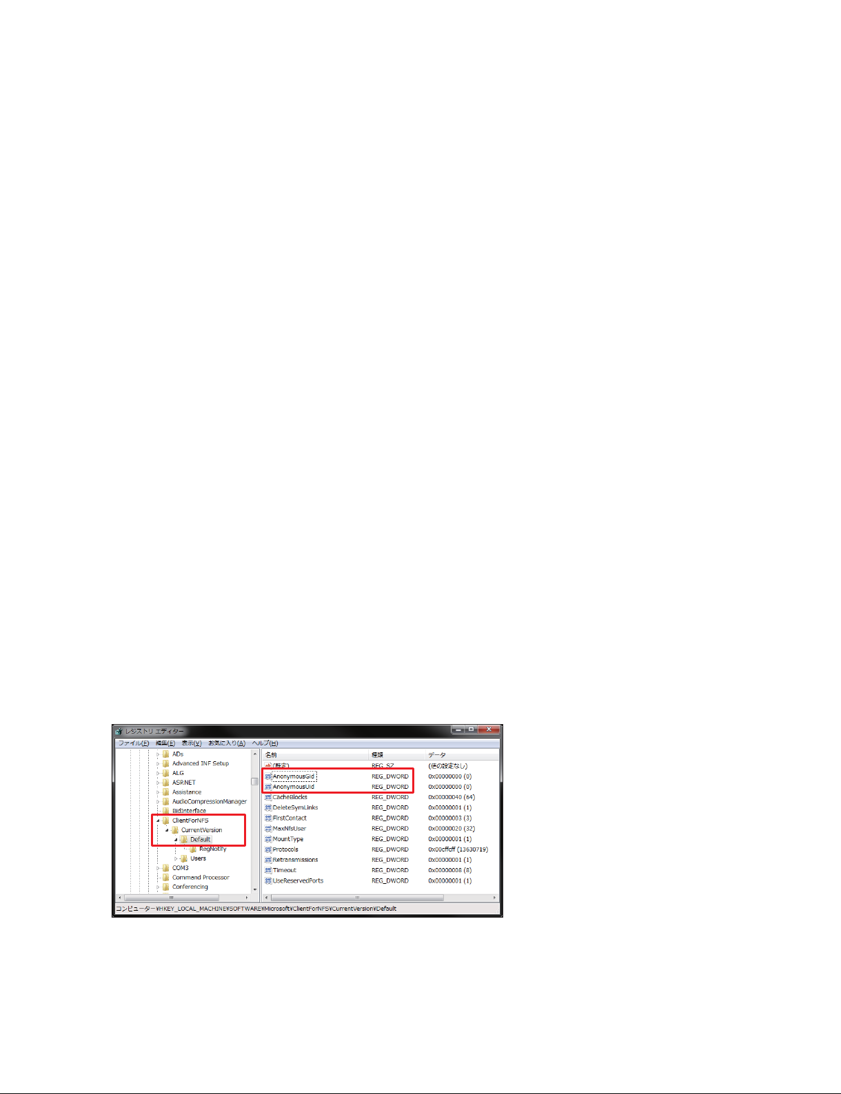
1. Enable the NFS client in the following procedures.
(1) Click on the Start button, click [Control Panel], click [Uninstall or change a program], and then
click [Turn Windows features on or off].
(2) In the Windows Features list, place a check mark in [Services for NFS], and then place a check
mark in [NFS client].
(3) Click [OK].
2. Set the group ID and the user ID in the following procedures.
(1) Click on the Start button, and then click [Run].
(2) Enter “regedit”, and then click [OK].
(3) Click the folder in the following sequence.
[HKEY_LOCAL_MACHINE], [SOFTWARE], [Microsoft], [ClientForNFS], [CurrentVersion],
[Default]
(4) Add the following keys to the [Default] folder.
AnonymousGid = 0 (DWORD 32bit)
AnonymousUid = 0 (DWORD 32bit)
(5) Restart the PC. Registry is enabled.
1-2 (E)
CLX101ASA/ZRD-1/ZRD-2/CLF101AKA/ZRCT-100
Page 7
1-2. Starting Color Uniformity Alignment Software
n
Remove all network connections from the PC before starting Color Uniformity Alignment Software.
(1) Click “Computer” or “This PC”.
t
Depending on the OS, open Windows Explorer and click “This PC”.
(2) When any drives are displayed in “Network Location”, select “Map Network Drive”, then select
“Disconnect Network Drive”. Remove all network connections.
When you activate Color Uniformity Alignment Software first time in the system, or when
a profile that was used in the previous adjustment cannot be read
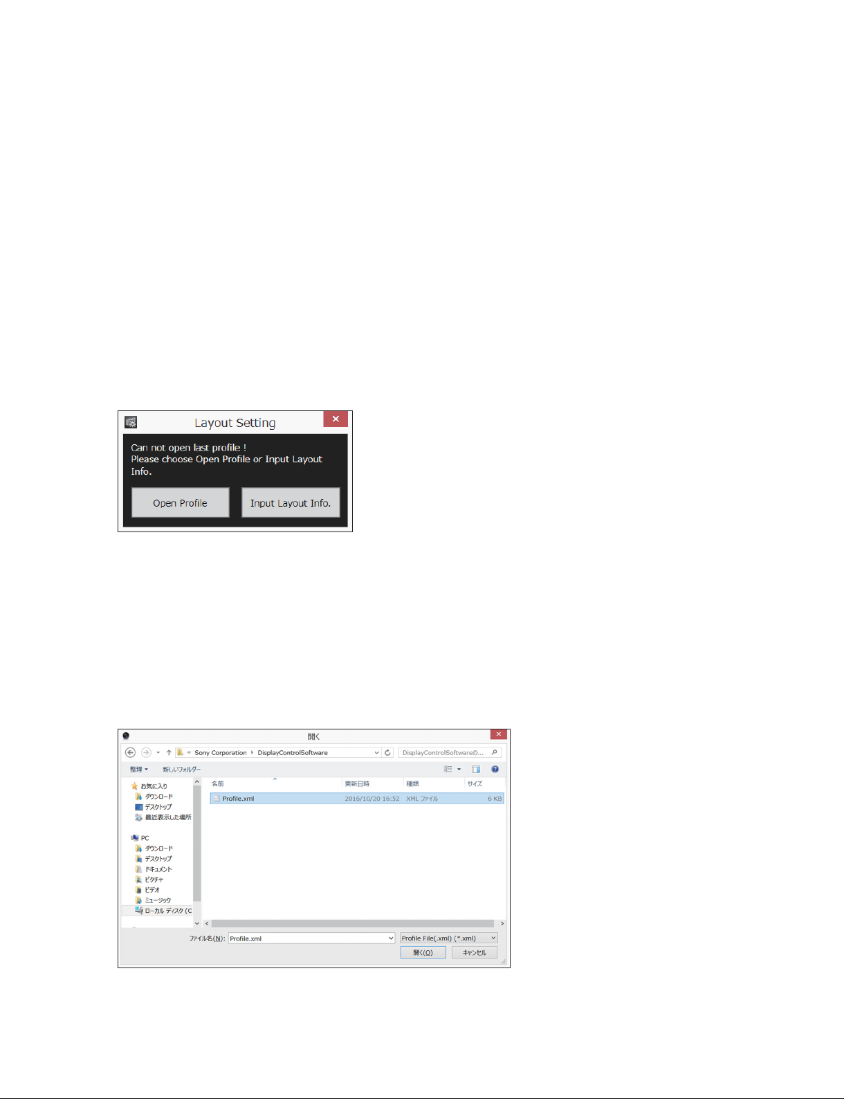
1. Double-click “CAS.exe”.
The following dialog is displayed.
The operation of step 2 and later varies depending on the Profile that you want to use.
When you use the Profile (Profile.xml) saved in the Display Control Software
2. Click [Open Profile].
The file selection screen is displayed.
3. Select “Profile.xml”, and then click [OK].
Folder in which Profile.xml file is placed:
C: \Users\<User>\AppData\Roaming\Sony Corporation\DisplayControlSoftware\Profile.xml
(In <User>, an individual name is displayed.)
CLX101ASA/ZRD-1/ZRD-2/CLF101AKA/ZRCT-100
1-3 (E)
Page 8
In the case that a folder is not displayed
Click on the Start button, click [Control Panel], and then click [Folder Options]. In the [View] tab,
place a check mark in [Show hidden files, folders, and drives].
The Data screen is displayed. (Refer to Section 1-3.)
When you create the Profile from the display controller
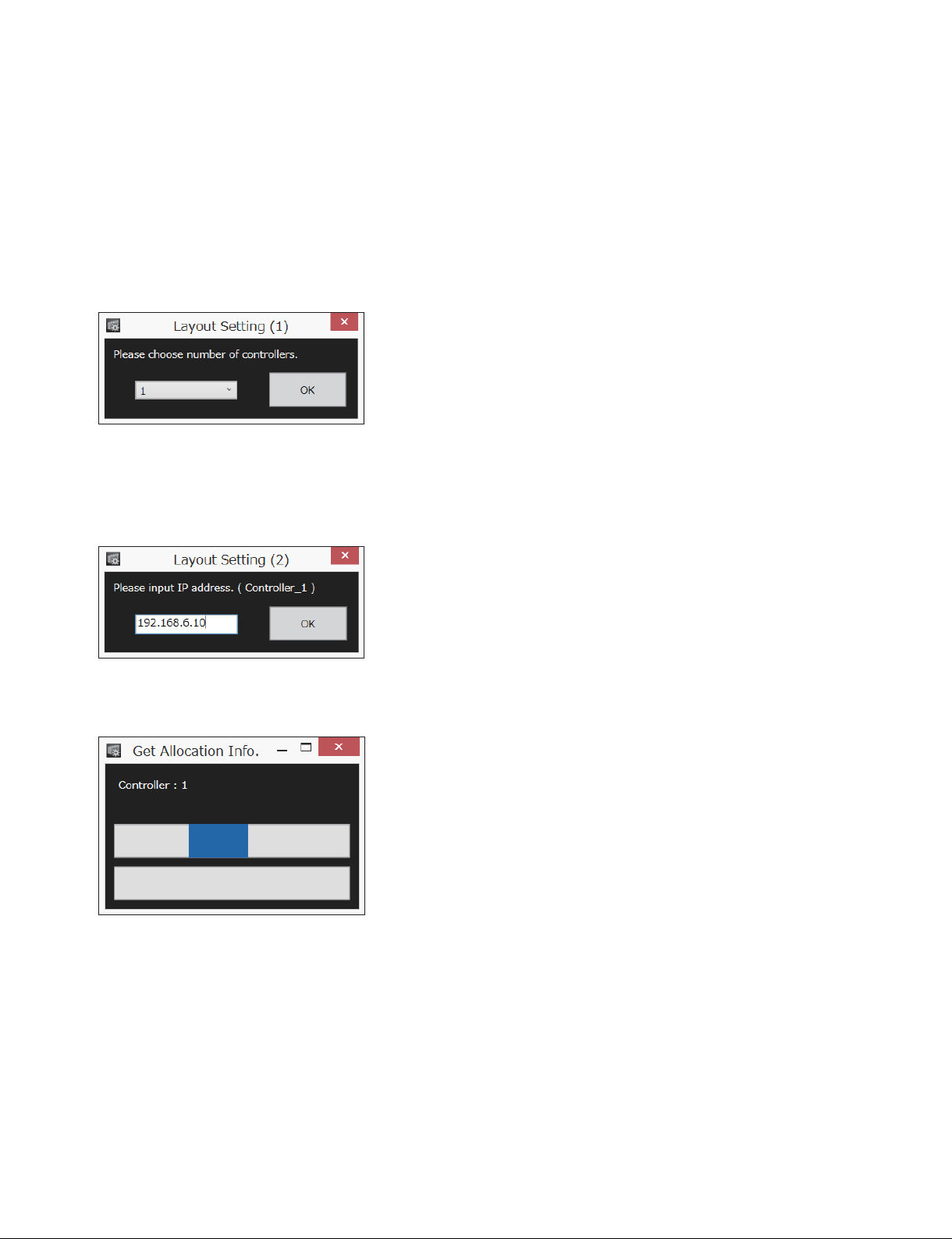
2. Click [Input Layout Info.].
The following dialog is displayed.
3. Select the number of the display controllers, and then click [OK].
4. Type the IP address of the display controller, and then click [OK].
In the case of the system using two or more display controllers, there is no problem to type the IP
address in any order.
The following dialog is displayed. It takes approximately two or three minutes until the Data screen is
displayed.
When the system connection is completed, the Data screen is displayed. (Refer to Section 1-3.)
5. On the menu bar, click [File], and then click [Save]. Select the [Profile] folder, and then type a file
name. Click [OK].
1-4 (E)
CLX101ASA/ZRD-1/ZRD-2/CLF101AKA/ZRCT-100
Page 9
When a profile that was used in the previous adjustment can be read
1. Double-click “CAS.exe”.
Color Uniformity Alignment Software is activated.
The Data screen that was displayed when the Color Uniformity Alignment Software is activated in
the previous time is displayed. (Refer to Section 1-3.)
To change the unit layout information after activation
On the menu bar, click [File].
[New]: Refer to “When you create the Profile from the display controller” described above.
[Open]: Refer to “When you use the Profile (Profile.xml) saved in the Display Control Software” de-
scribed above.
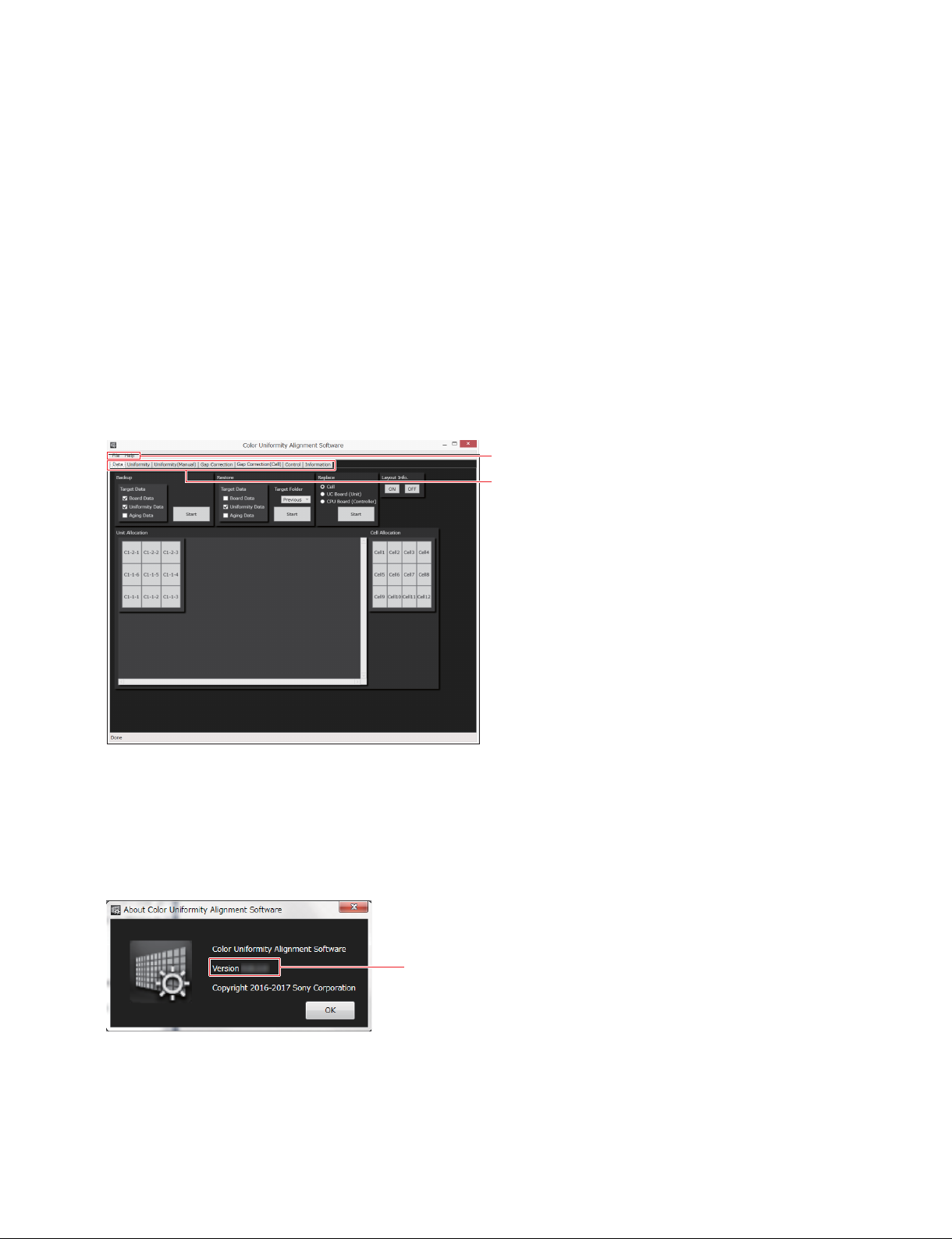
1-3. Features of Screen
Menu bar
Tab
t
In the screen and a message on the dialog, Color Uniformity Alignment Software may be abbreviated as
“CAS”.
To confirm the version of Color Uniformity Alignment Software (Version 1.10 and later)
On the menu bar, click [Help], and then click [About Color Uniformity Alignment Software].
Version
CLX101ASA/ZRD-1/ZRD-2/CLF101AKA/ZRCT-100
1-5 (E)
Page 10
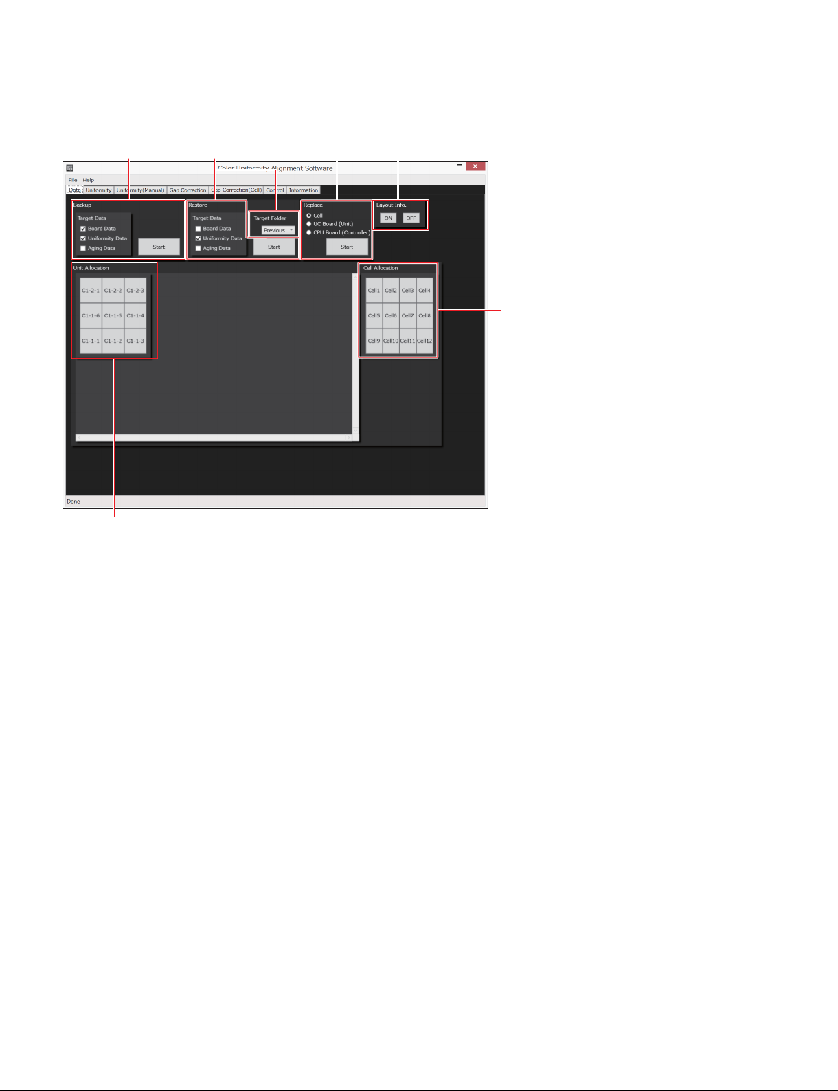
1-3-1. Data Screen
4
21
3 6
5
1 [Backup]
For reading the data from the display unit for backup
The all display units connecting to the display controller are the target to be read. You can not specify a
particular display unit.
When you back up an initial data, you do not select [Aging Data] because the total display time is 0.
[Target Data]: Target data to be read
. [Board Data]: Board adjustment data
. [Uniformity Data]: Uniformity correction data
. [Aging Data]: Total display time data
2 [Restore]
For restoring the data on a PC to the display unit
Specify the target display unit in [Unit Allocation].
From the following data (folder) in the [Backup] folder on the PC, select the data to be restored.
[Target Folder]: Select the target folder to be restored in the pull-down.
. [Initial] folder: The data when the display unit is backed up first time
The data in this folder is not overwritten.
. [Previous] folder: The data when the display unit is adjusted in previous time
Select this folder when you want to return the data of the display unit because of
adjustment failure.
. [Temporary] folder: The temporary data in correcting
Select this folder when the data restoration into the display unit is failed, or after
you perform [Installation (Measure Only)].
1-6 (E)
CLX101ASA/ZRD-1/ZRD-2/CLF101AKA/ZRCT-100
Page 11
[Target Data]: Target data to be read
. [Board Data]: Board adjustment data
. [Uniformity Data]: Uniformity correction data
. [Aging Data]: Total display time data
3 [Replace]
. [Cell]: The item to be used after a cell is replaced
Reads a correction data from a USB memory, and then writes the data to the
display unit.
. [UC Board (Unit)]: The item to be used when a UC board is replaced
Reads the data in the UC board before replacement, and then writes the
data in the UC board after replacement. Perform the actions in sequence
from before replacement to after replacement.
. [CPU Board (Controller): The item to be used after a CPU board is replaced
Writes the serial number of the display controller into the CPU board.
4 [Unit Allocation]
Specify the target display unit. The color of the specified display unit changes to blue on the map.
5 [Cell Allocation]
Specify the target cell after you specify the display unit in [Unit Allocation]. The color of the specified
cell changes to blue on the map.
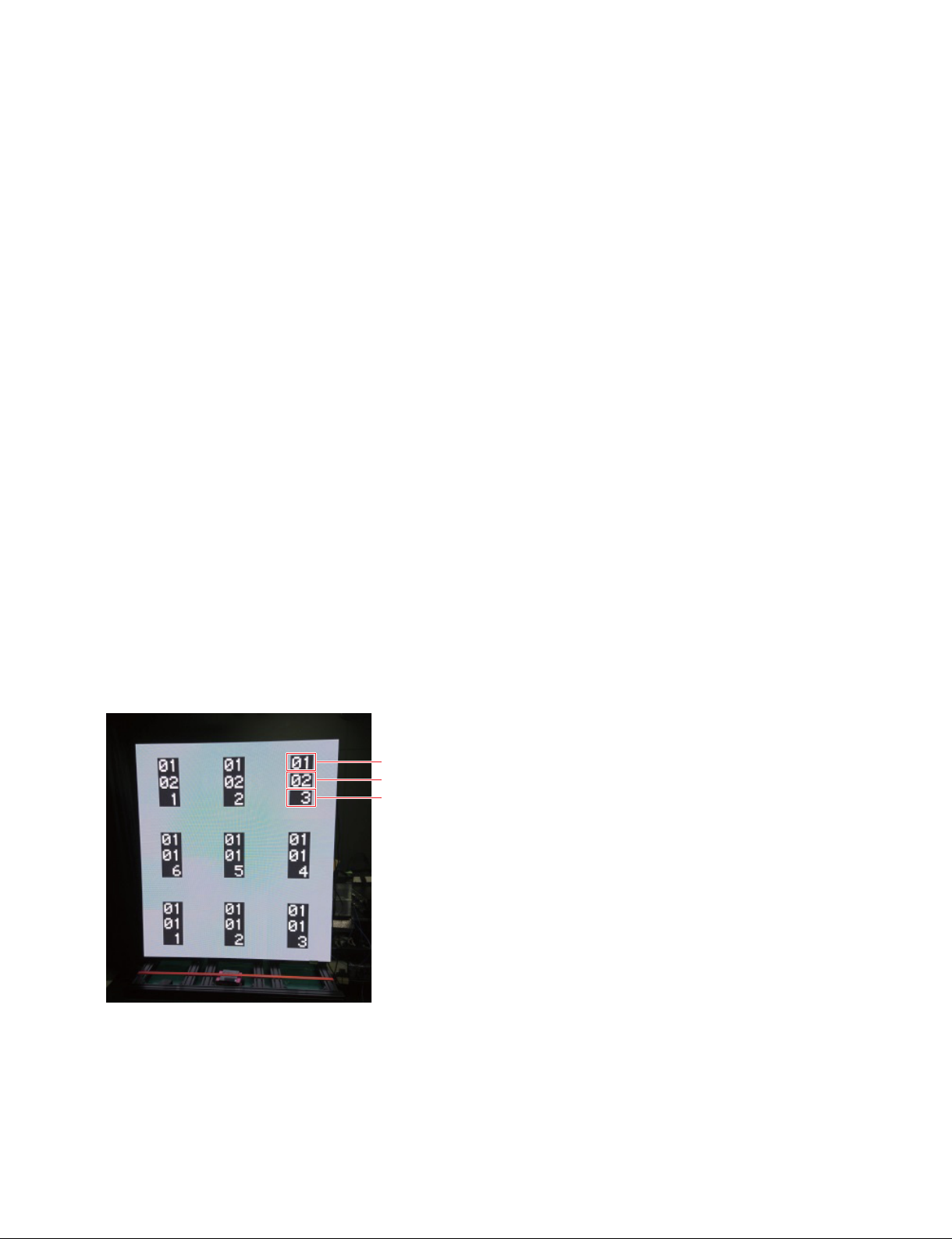
6 [Layout Info.] (Version 1.10 and later)
Displays the unit layout address of the display units on the array. The unit layout addresses are displayed
when you select “ON”, and the addresses are cleared when you select “OFF”.
The unit layout addresses can be displayed even when a test pattern or an external video signal is displayed.
Top : Controller No. (01-20)
Middle : Port No. (01-12)
Bottom : Unit No. (1-6)
CLX101ASA/ZRD-1/ZRD-2/CLF101AKA/ZRCT-100
1-7 (E)
Page 12
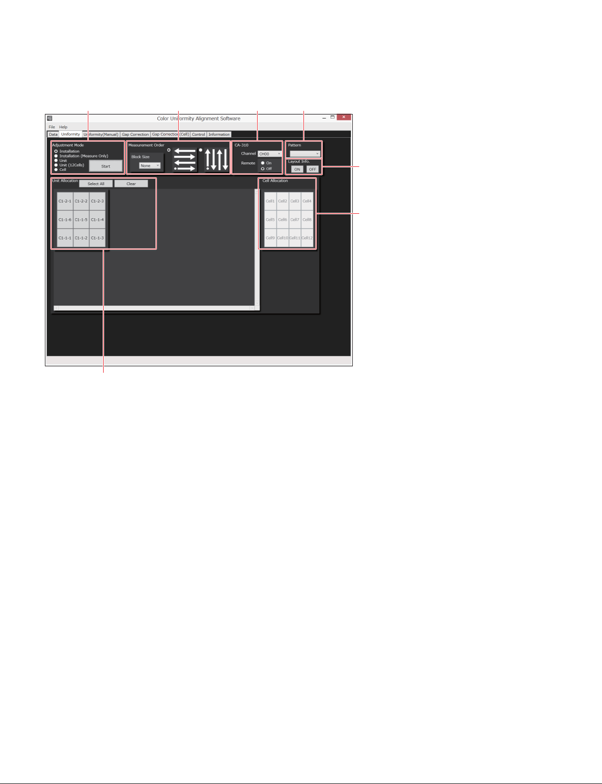
1-3-2. Uniformity Screen
5
21
3 4
7
6
1 [Adjustment Mode]
Select the adjustment mode.
. [Installation]: For uniformity adjustment in installation
Adjusts the whole array.
. [Installation (Measure Only)]: Only measures the uniformity in the whole array. Measure the unifor-
mity in several times, and then restore the data in [Restore] on the Data
screen at the end of adjustment because it takes time to restore the data.
. [Unit]: Mode that the target display unit is matched to the adjacent display
units. Use this mode in UC board replacement mainly.
. [Unit (12Cells)]: In [Unit (12Cells)], adjusts the all 12 cells, while in [Installation], the
four points are measured. Mode for fine adjustment
. [Cell]: Mode that the target cell is matched to the adjacent cells. Use this
mode in the cell replacement mainly.
2 [Measurement Order]
Select the direction of the measurement flow and the measurement block size shifting to the next block.
3 [CA-310]
Sets Color Analyzer CA-310.
. [Channel]: Select the channel that you want to use in measurement. Usually, “CH00” is used. When
you want to use the customized setting of CH01 or later of CA-310, select the channel.
. [Remote]: Set a remote mode of CA-310. Usually, the remote mode is set to “On” automatically when
you click [Start]. In the “On” mode, the measurement value is not displayed on CA-310.
Therefore, when you want to see the measurement value of luminance and chromaticity, set
to “Off”. The “Off” setting is kept until you click [Start] next time.
4 [Pattern]
Select a test pattern to be output.
1-8 (E)
CLX101ASA/ZRD-1/ZRD-2/CLF101AKA/ZRCT-100
Page 13
5 [Unit Allocation]
Specify the target display unit. The color of the specified display unit changes to blue on the map.
. [Select All]: Selects the all display units in the [Unit Allocation] map.
. [Clear]: Clears the selection of the all display units.
6 [Cell Allocation]
Specify the target cell after you specify the display unit in [Unit Allocation]. The color of the specified
cell changes to blue on the map.
7 [Layout Info.] (Version 1.10 and later)
Displays the unit layout address of the display units on the array. The unit layout addresses are displayed
when you select “ON”, and the addresses are cleared when you select “OFF”.
For the details on the display, refer to “6 Layout Info.” in “1-3-1. Data Screen”.
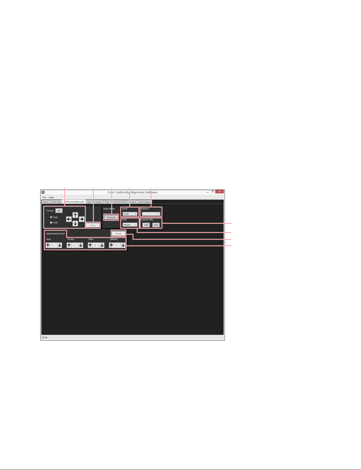
1-3-3. Uniformity (Manual) Screen (Version 1.10 and Later)
1
2 3 4 5
6
7
8
9
1 [Cursor]
Displays a cursor for selecting the adjustment point. The cursor is displayed when you select “On”, and
the cursor is cleared when you select “On” again.
. [Unit]: Select it to shift a cursor between the display units.
. [Cell]: Select it to shift a cursor between the cells in the display unit selected using [Unit].
. [ ↑ ][ ↓ ] [ ← ] [ → ]: Shift a cursor.
2 [Select]
Determinates the adjustment point. The cursor is cleared when you click [Select]. To see which display
unit or cell is selected, click [On] in [Cursor].
CLX101ASA/ZRD-1/ZRD-2/CLF101AKA/ZRCT-100
1-9 (E)
Page 14

3 [Execute]
Writes the adjusted luminance data in the display unit. Writes the data of all the display units or all the
cells whose luminance is changed.
4 [Level]
Selects a luminance of the array in the adjustment. 20%, 50%, or 100%. The default setting is 20%.
5 [Pattern]
Selects a test pattern to be output.
6 [Layout Info.] (Version 1.10 and later)
Displays the unit layout address of the display units on the array. The unit layout addresses are displayed
when you select “ON”, and the addresses are cleared when you select “OFF”.
For the details on the display, refer to “6 Layout Info.” in “1-3-1. Data Screen”.
7 [Color]
Selects the color on the array in the adjustment. White, Red, Green, or Blue. The default setting is White.
8 [Reset]
Returns the display unit not adjusted.
9 [Adjustment level]
Adjusts a luminance of selected display unit or selected cell.
When you adjust in [Red], [Green], or [Blue], the color of red, green, or blue changes separately. When
you adjust in [White], the colors of red, green, and blue change simultaneously in the same step.
You can select a step from five levels of [1] (0.5%) to [5] (2.5%) for each grade of change by 0.5%.
1-10 (E)
CLX101ASA/ZRD-1/ZRD-2/CLF101AKA/ZRCT-100
Page 15
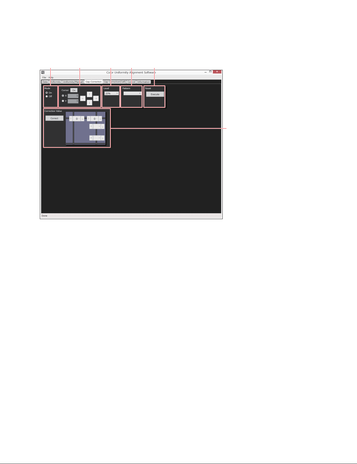
1-3-4. Gap Correction Screen
21
3 4 5
6
1 [Mode]
Switches the joint correction mode. Usually, “On” is used. When you want to check the effect of a joint
correction, switch between “Off” (setting before correction) and “On” (setting after correction).
2 [Cursor]
Displays a cursor for selecting the correction point. The cursor is displayed when you select “On”, and the
cursor is cleared when you select “On” again.
. [X]: Displays a cursor of horizontal line. Corrects a joint between the upper display unit
and the lower display unit.
. [Y]: Displays a cursor of vertical line. Corrects a joint between the right display unit and
the left display unit.
. [↑][↓] [←] [→]: Shifts a cursor.
3 [Level]
Selects a luminance of the array. 5%, 20%, or 50%. The default setting is 20%.
4 [Pattern]
Selects a test pattern to be output.
5 [Reset]
Returns the display unit not corrected. (Correction Value: All 0)
6 [Correction Value]
Corrects the target point. When you lick [Correct], the cursor is cleared and the correction is enabled.
CLX101ASA/ZRD-1/ZRD-2/CLF101AKA/ZRCT-100
1-11 (E)
Page 16
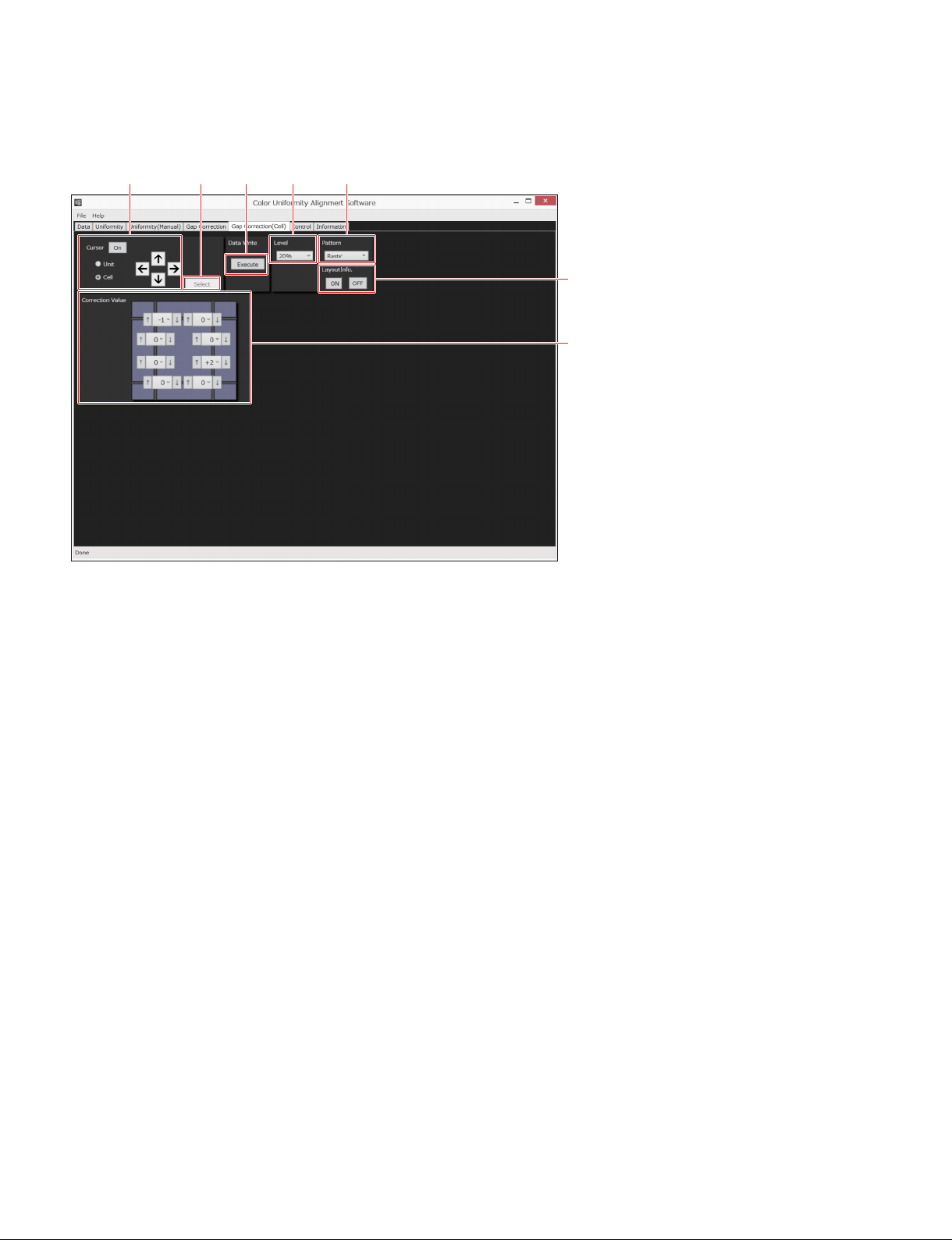
1-3-5. Gap Correction (Cell) Screen (Version 1.10 and Later)
21
435
6
7
1 [Cursor]
Displays a cursor for selecting the correction point. The cursor is displayed when you select “On”, and the
cursor is cleared when you select “On” again.
. [Unit]: Select it to shift a cursor between the display units.
. [Cell]: Select it to shift a cursor between the cells in the display unit selected using [Unit].
. [↑][↓][←][→]: Shift a cursor.
2 [Select]
Determinates the correction point. The cursor is cleared when you click [Select]. To see which cell is
selected, click [On] in [Cursor].
3 [Execute]
Writes the corrected luminance data in the display unit. Writes the data of the cell whose luminance is
changed.
4 [Level]
Selects a luminance of the array in the correction. 20%, 50%, or 100%. The default setting is 20%.
5 [Pattern]
Selects a test pattern to be output.
6 [Layout Info.]
Displays the unit layout address of the display units on the array. The unit layout addresses are displayed
when you select “ON”, and the addresses are cleared when you select “OFF”.
For the details on the display, refer to “6 Layout Info.” in “1-3-1. Data Screen”.
7 [Correction Value]
Corrects the target point.
1-12 (E)
CLX101ASA/ZRD-1/ZRD-2/CLF101AKA/ZRCT-100
Page 17
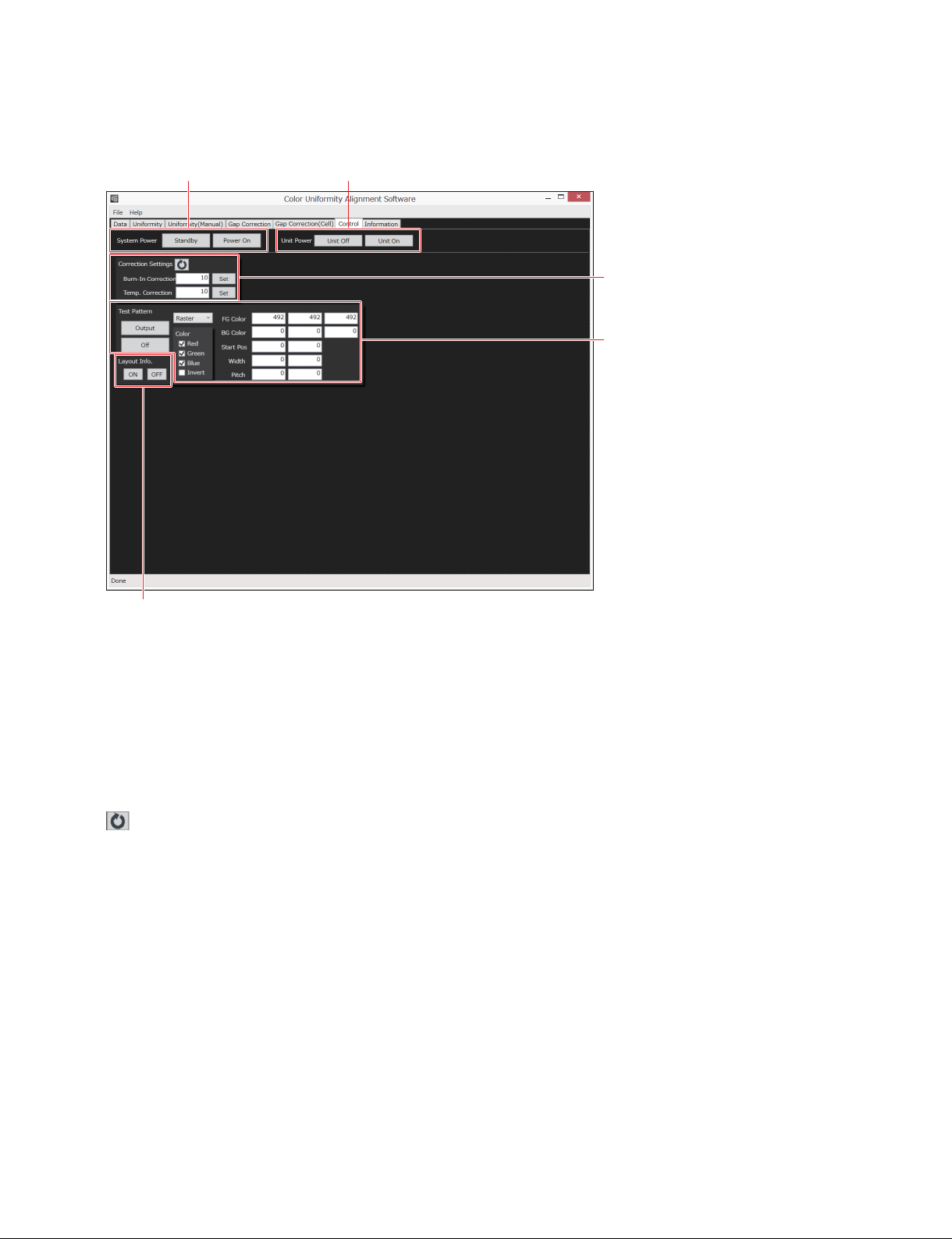
1-3-6. Control Screen
21
3
4
5
1 [System Power]
Turns on the system or turns off the system.
[System Power] of Color Uniformity Alignment Software has the same function as [System Power] of
Display Control Software and as the power switch of the display controller.
2 [Unit Power]
Turns on the display unit or turns off the display unit.
3 [Correction Settings]
: Reads the values of [Burn-In Correction] and [Temp. Correction] that are set in
the display controller.
[Burn-In Correction]: Sets a reference darkness level (0 to 10) to correct a burn-in. Usually, the default
value (10) is used. When you want to change the level, click [Reload] to read the
current value, type the value by the numeric keys on the PC, and then click [Set].
[Temp. Correction]: Absorbs a color difference that occurs by the temperature difference between the
display units. Set a correction level (0 to 10) against the adjacent display units.
Usually, the default value (10) is used. When you want to change the level, click
[Reload] to read the current value, type the value by the numeric keys on the PC,
and then click [Set].
CLX101ASA/ZRD-1/ZRD-2/CLF101AKA/ZRCT-100
1-13 (E)
Page 18

4 [Test Pattern]
Select an internal test pattern of the display controller in the pull-down.
[Output]: Displays the test pattern to the array.
[Off]: Clears the test pattern display on the array, and then displays the video from the source equip-
ment.
You can change the following settings.
. [Color]: Color combinations of a test pattern
. [FG Color]: Gradation of color to be displayed in front ground
t
[492]: 20%
[747]: 50%
. [BG Color]: Gradation of color to be displayed in back ground
t
[492]: 20%
[747]: 50%
. [Start Pos]: Display starting coordinate
. [Width]
. [Pitch]
5 [Layout Info.] (Version 1.10 and later)
Displays the unit layout address of the display units on the array. The unit layout addresses are displayed
when you select “ON”, and the addresses are cleared when you select “OFF”.
For the details on the display, refer to “6 Layout Info.” in “1-3-1. Data Screen”.
1-14 (E)
CLX101ASA/ZRD-1/ZRD-2/CLF101AKA/ZRCT-100
Page 19
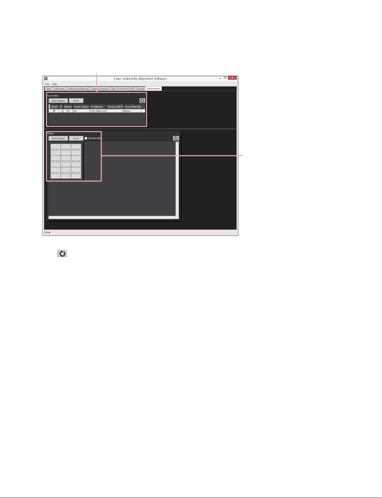
1-3-7. Information Screen
1
2
1 [Controller]
Click to update the information. The information is not read automatically.
. [Information]: Obtains the board information and the firmware version, and displays them.
. [Error]: Obtains the error data and the warning data, and displays them.
. [Error/Warning]: Displays the error or the warning, if it occurs.
2 [Panel]
The map of the all display units connecting to the system is displayed. A display unit that has an error is
displayed in red. A display unit that has a warning is displayed in yellow.
. [Information]: Displays the board information and the firmware version that was backed up. When you
want to see the latest data, click [Reload info].
. [Error]: Obtains the error data and the warning data, and displays them.
. [Reload info]: Reads the data from the display controller. Select when the data of the display unit was
not backed up.
CLX101ASA/ZRD-1/ZRD-2/CLF101AKA/ZRCT-100
1-15 (E)
Page 20

Page 21
Section 2
Operation in Array Installation
A display unit is shipped from the factory after adjustment. But it is recommended to adjust the uniformity
of the array after the system (array) is installed, so that a joint is invisible.
2-1. Preparation
2-1-1. Required Items
. PC
- OS:
. Windows 7 Enterprise or Ultimate
. Windows 8.1 Enterprise
. Windows 10 Enterprise
n
Windows 8 and Edition other than the above (such as Professional) are not supported.
- Wireless mouse is recommended.
. Display Color Analyzer CA-310 (Konica Minolta), or equivalent
Install the CA-310’s driver software and the color analyzer’s PC software CA-SDK on PC. The driver
software and CA-SDK are stored in a CD-ROM supplied with CA-310.
. USB cable (type A - type B)
. Ethernet cable (category 5)
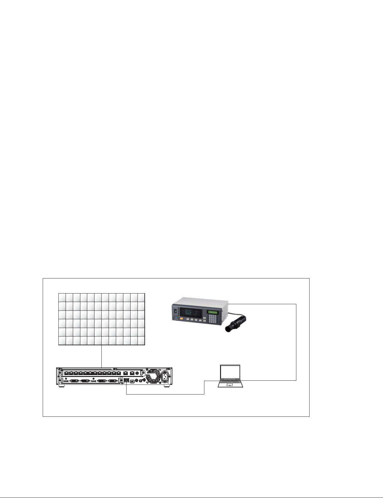
2-1-2. Connection
Array (Display units)
Refer to Section 5 in the
Installation Manual.
Display controller
Ethernet cable (category 5)
Display Color Analyzer CA-310
Probe
PC on which the Color
Uniformity Alignment
Software is installed
2-2. Starting Color Uniformity Alignment Software
USB cable
(type A - type B)
Refer to Section 1-2. The Data screen is displayed.
CLX101ASA/ZRD-1/ZRD-2/CLF101AKA/ZRCT-100
2-1 (E)
Page 22
2-3. Backing Up the Data
This procedure needs to be done only once when you adjust the uniformity in first time after the array is
installed. Be sure to back up the data so as to obtain the individual initial data of the all display units.
In the second and subsequent times, this procedure is not required.
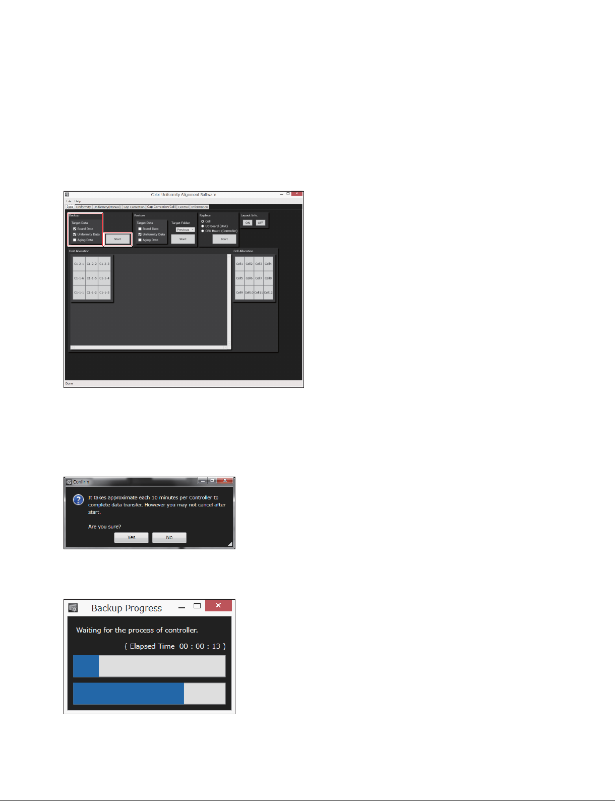
1. On [Target Data] of [Backup] in the Data screen, place a check mark in [Board Data] and [Uniformity
Data]. Clear a check mark in [Aging Data].
2. Click [Start] of [Backup].
The following dialog is displayed.
n
The backup takes approximately 20 seconds per display unit. The backup time increases as the num-
ber of display units increases.
3. Click [Yes].
The following dialog is displayed.
2-2 (E)
CLX101ASA/ZRD-1/ZRD-2/CLF101AKA/ZRCT-100
Page 23
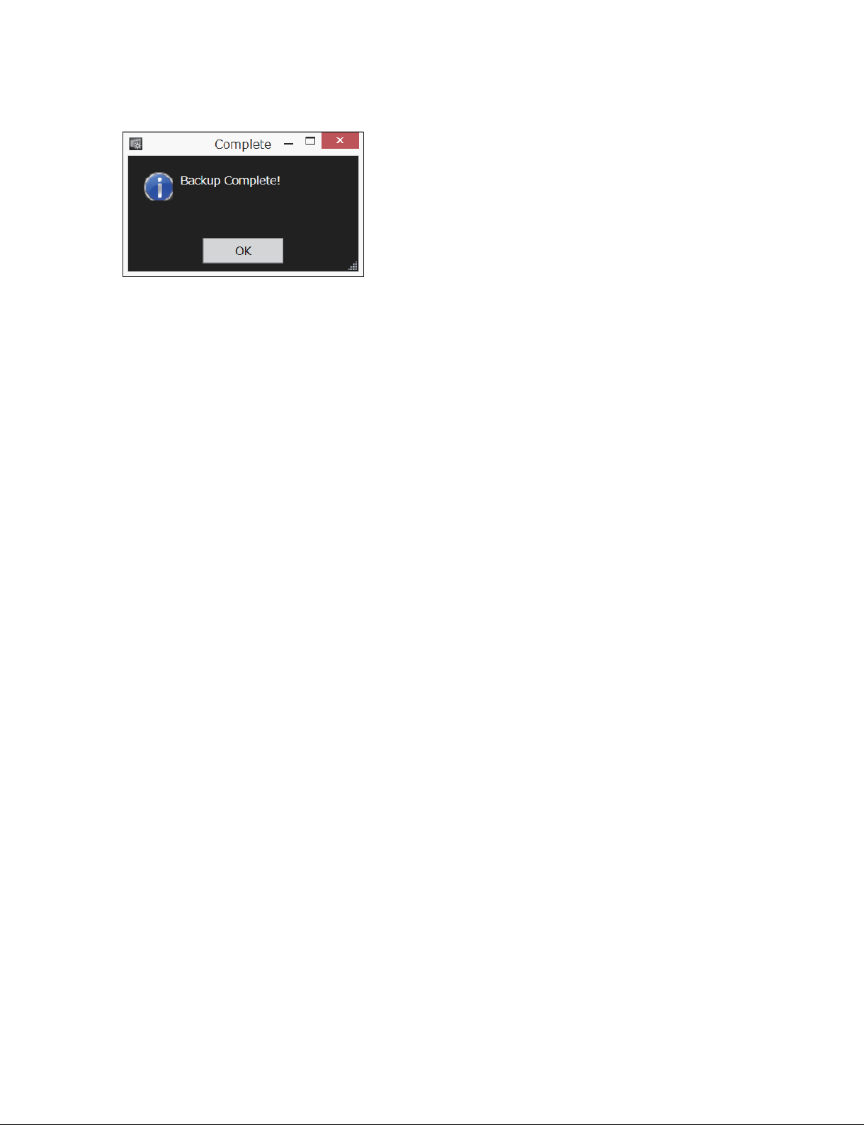
When the backup is completed, the following dialog is displayed.
4. Click [OK].
The display returns to the Data screen.
About the backup data
The backup data is stored in the [Backup] folder in the PC.
In the [Backup] folder, the following three generation data are stored.
. [Initial] folder: The data when the display unit is backed up first time. The data in this folder is not
overwritten.
. [Previous] folder: The data when the display unit is adjusted in previous time.
. [Latest] folder: The latest data written in the display unit
t
The [Temporary] folder is created when you perform [Installation (Measure Only)] or when the data
restoration into the display unit is interrupted. The data up to the middle is stored. For the restoration of
the data in the [Temporary] folder, refer to “2-7. Restoring Measurement Data”.
CLX101ASA/ZRD-1/ZRD-2/CLF101AKA/ZRCT-100
2-3 (E)
Page 24
2-4. Uniformity Adjustment
n
In the case of the system using two or more display controllers, be sure to adjust the uniformity under the
condition that the display controllers are linked each other.
1. Connect a PC to Display Color Analyzer CA-310. (Refer to Section 2-1-2.)
2. Start the CA-310, and then execute the 0-calcuration. For details on how to operate the 0-calcuration,
refer to an instructions of CA-310.
n
After the 0-calcuration is completed, set the probe to [Measure].
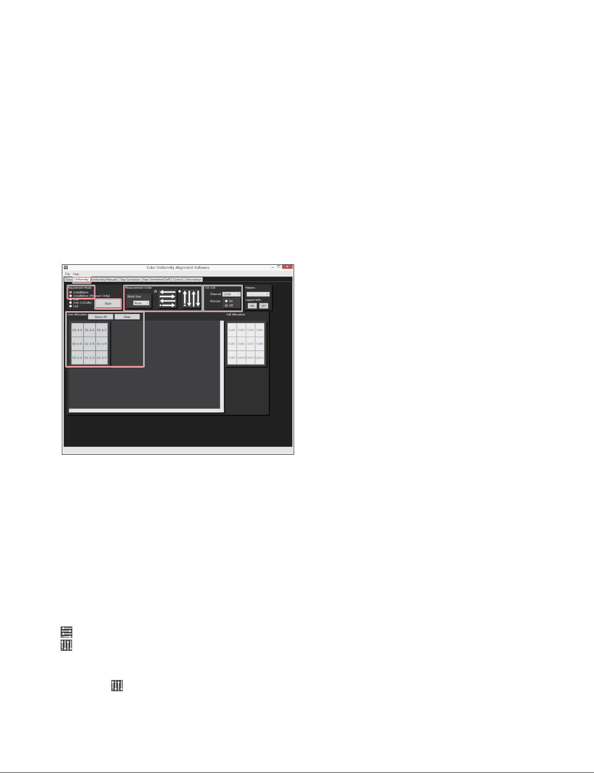
3. On the Data screen, click the [Uniformity] tab.
The Uniformity screen is displayed.
4. Click [Installation] in [Adjustment Mode].
t
In the case that [Installation] is selected, it executes in sequence from a measurement of the luminance
and chromaticity to a restoring the measurement results.
When you want to execute the restoring the measurement results separately from a measurement of
the luminance and chromaticity, refer to Section 2-6 and Section 2-7.
5. Click the display units that you want to adjust in [Unit Allocation].
The color of the specified display unit changes to blue on the map.
[Select All]: Selects all display units in the [Unit Allocation] map.
[Clear]: Clears the selection of all display units.
6. Select the block size and the direction of shift in [Measurement Order].
: Suitable for the landscape-oriented screen.
: Suitable for the portrait-oriented screen such as using a lifter
[Block Size]: Select the measurement size (block) to shift in the horizontal direction or in the vertical
direction.
If you select
and “3x3” block, for example, the measurement target display unit is shifted in the
vertical direction every time the measurement of 3x3 block has been completed.
2-4 (E)
CLX101ASA/ZRD-1/ZRD-2/CLF101AKA/ZRCT-100
Page 25
7. Set the following item as required.
. [Channel] in [CA-310]: Usually, “CH00” is used when CA-310 is not customized. If you want to
use the customized setting, select the channel that that customized setting
is registered in.
t
It is not necessary to set [Remote] and [Pattern] in [CA-310]. The setting of [Remote] in [CA-310]
operates as “On” and the setting of [Pattern] operates as [Raster] automatically.
8. Click [Start].
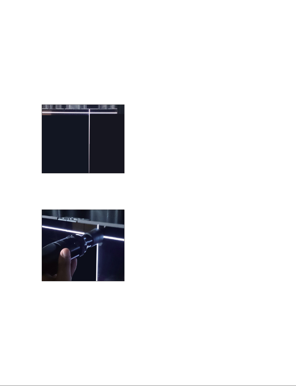
The dialog is displayed on the display of the PC. A cross-cursor is displayed on the array.
9. Touch the probe of the CA-310 to the cross-cursor. While touching the probe, click the mouse.
n
. Touch the center of the probe to the intersection of the cross-cursor.
. Touch the probe softly and vertically against the cross-cursor.
The chromaticity is measured automatically in the following sequence: R, G, B.
When a point is measured, the cross-cursor will shift to the next measurement point.
t
When you want to stop the measurement, press the [Esc] key on the PC. The data up to the middle is
stored in the [Temporary] folder in the [Backup] folder. For the restoration of the data in the [Temporary] folder, refer to “2-7. Restoring Measurement Data”.
CLX101ASA/ZRD-1/ZRD-2/CLF101AKA/ZRCT-100
2-5 (E)
Page 26
10. Repeat the operation of step 9.
When the measurement is completed, the cross-cursor will disappear.
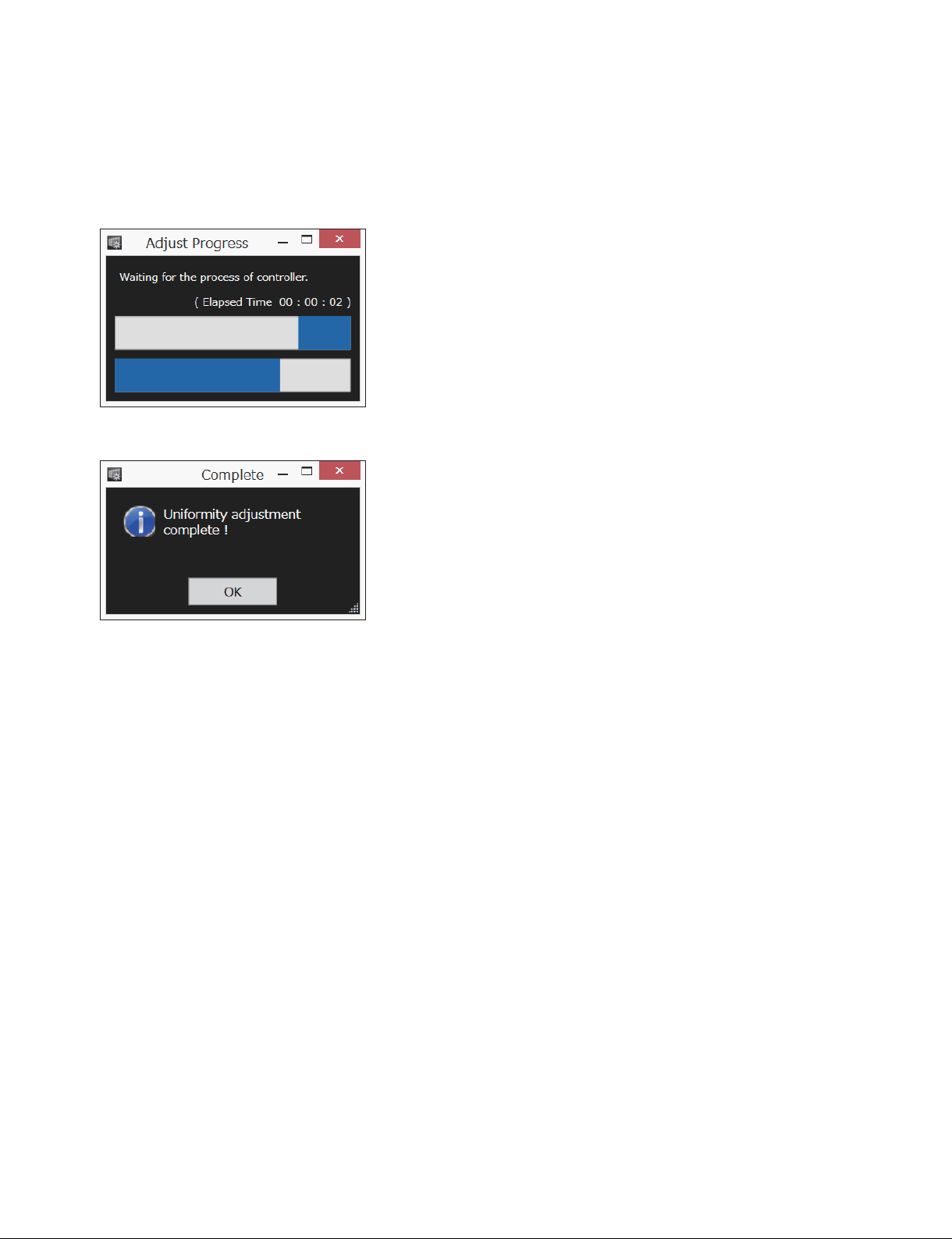
The restoration of the measurement data starts. The following dialog is displayed.
The restoration takes approximately 50 seconds per display unit. The restoration for the array in the
FHD size (18 display units), for example, takes approximately 15 minutes.
When the restoration is completed, the following dialog is displayed.
11. Click [OK].
A raster image (a white screen) is displayed in the array.
12. Check the array visually. If there is no unevenness on the array, select “Off” in [Pattern].
A video signal that is input from the external equipment is displayed on the array.
In the case that there is unevenness on the array
Adjust the uniformity of a display unit or a cell with unevenness separately. (Refer to Section 2-8 and
Section 2-9.)
To see a value of the luminance and chromaticity of the adjusted array
1. Select a test pattern in [Pattern] on the Uniformity screen.
2. Set [Remote] to “Off” in [CA-310].
3. Touch the probe of CA-310 to the display unit or the cell that you want to see the value.
The value of the luminance and chromaticity is displayed on the indication window of CA-310.
2-6 (E)
CLX101ASA/ZRD-1/ZRD-2/CLF101AKA/ZRCT-100
Page 27
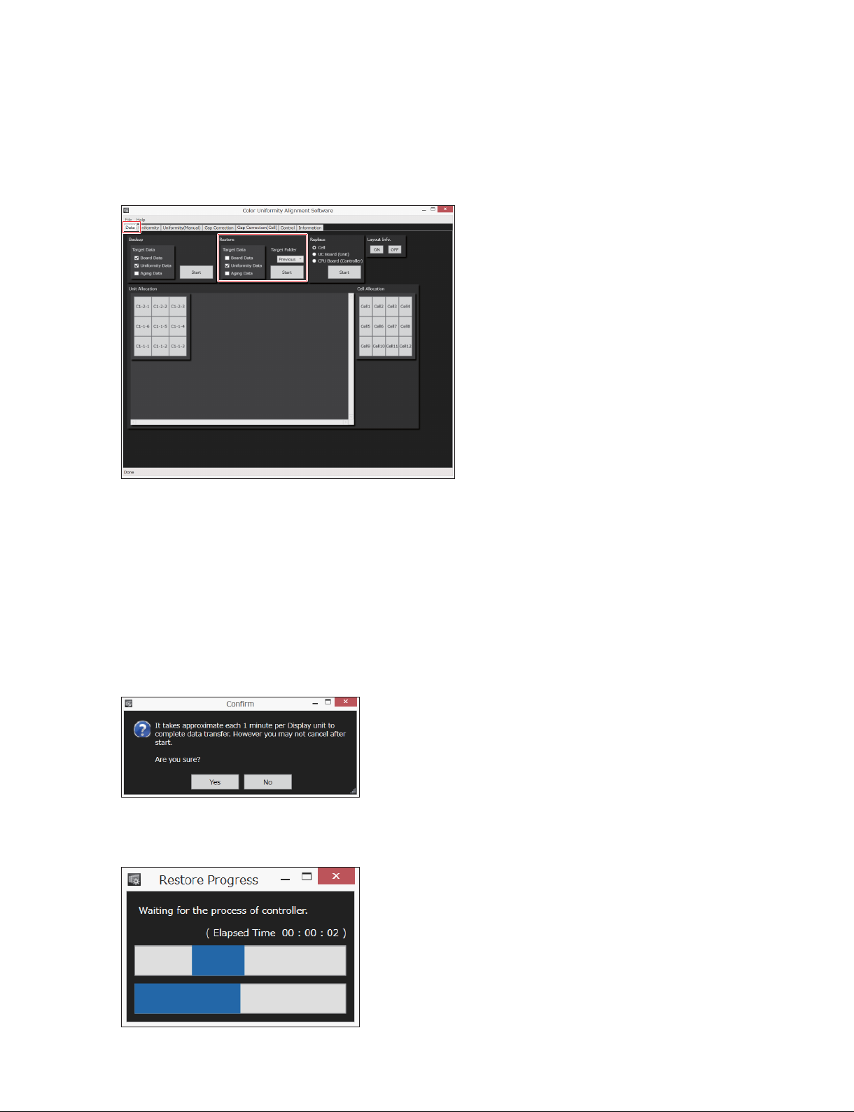
To return to the array before the adjustment
You can return the data for each display unit.
1. Click the [Data] tab.
The Data screen is displayed.
2. On [Target Data] of [Restore], place a check mark in [Uniformity Data]. Clear a check mark in [Board
Data] and [Aging Data].
3. Select the [Previous] folder in [Target Folder].
4. Click the display unit in [Unit Allocation], that you want to return the data.
The color of the specified display unit changes to blue on the map.
5. Click [Start] of [Restore].
The following dialog is displayed.
n
The restoration takes approximately 50 seconds per display unit. The restoration time increases as the
number of display units increases.
6. Click [Yes].
The following dialog is displayed.
CLX101ASA/ZRD-1/ZRD-2/CLF101AKA/ZRCT-100
2-7 (E)
Page 28
When the restoration is completed, the following dialog is displayed.
7. Click [OK].
The display returns to the Data screen.
2-5. Joint Correction (Gap Correction)
The joint correction enables the joint (seam) between the display units to be less conspicuous.
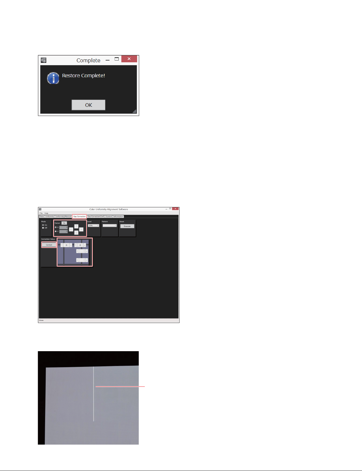
1. Click the [Gap Correction] tab in the Data screen.
The Gap Correction screen is displayed.
2. Set [Cursor] to “On”.
A cursor is displayed on the array.
2-8 (E)
Cursor
CLX101ASA/ZRD-1/ZRD-2/CLF101AKA/ZRCT-100
Page 29

3. Select the luminance of the array as required.
[5%]: Dark
[20%]: Standard bright (default)
[50%]: Bright
4. Shift the cursor to the position that you want to correct by using the arrow keys.
To correct a joint in the horizontal direction, place a check mark in [X]. To correct a joint in the
vertical direction, place a check mark in [Y].
5. Click [Correct].
6. Change the correction value (_12 to +12) displayed next to [Correct]. Default: 0 (no correction)
When you select the setting value in the pull-down or when you set it by the arrow keys, the setting
value is transmitted to the array. In the arrow keys, the setting value is transmitted every time you
press the arrow key.
It takes approximately 6 seconds until the setting value is reflected to the array.
The setting value after changing is stored in the display controller automatically.
To check the correction result
Set [Mode] to “Off” and “On” alternately. When “Off” is selected, the display before correction appears
on the array, and when “On” is selected, the display after correction appears on the array.
2-6. Only Measuring Luminance and Chromaticity
It takes time to restore the data. In the big size of array, it is difficult to measure the whole area of the
array at once. You can control the working time by dividing the array for several areas, measuring them,
and restoring the values of the data together at the end.
1. Display the Uniformity screen. (Refer to step 1 to step 3 in “2-4. Uniformity Adjustment”.)
2. Click [Installation (Measure Only)] in [Adjustment Mode].
3. Measure the luminance and chromaticity. (Refer to step 5 to step 10 in “2-4. Uniformity Adjustment”.)
When the measurement of the specified display unit is completed, the following dialog is displayed.
4. Click [OK].
5. Measure the next area. (Refer to step 3 and step 4,)
6. After measuring all areas, select “Off” in [Pattern].
The display on the array changes to the picture that is input from the external equipment.
7. Restore the data. (Refer to Section 2-7.)
CLX101ASA/ZRD-1/ZRD-2/CLF101AKA/ZRCT-100
2-9 (E)
Page 30
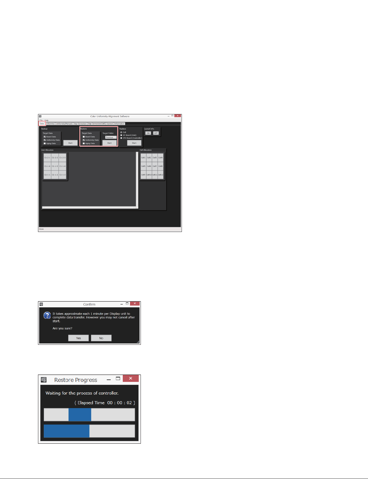
2-7. Restoring Measurement Data
Restore data in the [Temporary] folder to the display unit. Perform the following operations when you
want to execute the restoration of the measurement results separately from a measurement of the luminance and chromaticity or when the data restoration into the display unit is interrupted.
1. Click the [Data] tab.
The Data screen is displayed.
2. On [Target Data] in [Restore], place a check mark in [Uniformity Data]. Clear a check mark in [Board
Data] and [Aging Data].
3. Select [Temporary] in the pull-down in [Target Folder].
The following dialog is displayed.
n
The restoration takes approximately 50 seconds per display unit. The restoration time increases as the
number of display units increases.
4. Click [Yes].
The following dialog is displayed.
2-10 (E)
CLX101ASA/ZRD-1/ZRD-2/CLF101AKA/ZRCT-100
Page 31
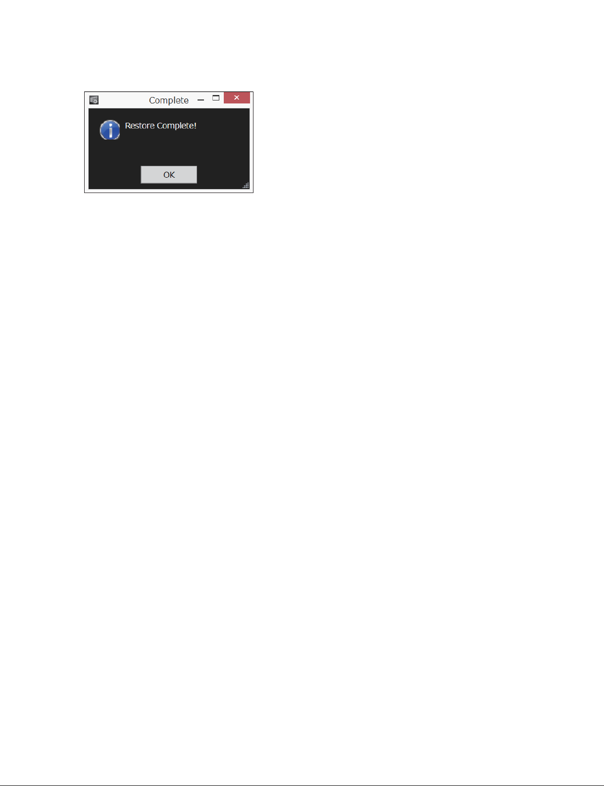
When the restoration is completed, the following dialog is displayed.
5. Click [OK].
The display returns to the Data screen.
2-8. Adjusting Display Unit with Unevenness Separately
Match the luminance and chromaticity of the display unit to be adjusted to the adjacent display units.
1. Display the Uniformity screen. (Refer to step 1 to step 3 in “2-4. Uniformity Adjustment”.)
2. Click [Unit] in [Adjustment Mode].
3. Click the display units that you want to adjust in [Unit Allocation].
The color of the specified display unit changes to blue on the map.
4. Adjust the uniformity. (Refer to step 8 to step 12 in “2-4. Uniformity Adjustment”.)
t
In the version 1.10 and later, you can adjust a display unit visually with ease if you have to adjust it in a
hurry. (Refer to Section 3-6.)
2-9. Adjusting Cell with Unevenness Separately
Match the luminance and chromaticity of the cell to be adjusted to the adjacent cells.
1. Display the Uniformity screen. (Refer to step 1 to step 3 in “2-4. Uniformity Adjustment”.)
2. Click [Cell] in [Adjustment Mode].
3. Click the display units that you want to adjust in [Unit Allocation].
The color of the specified display unit changes to blue on the map.
4. Click the cell that you want to adjust in [Cell Allocation].
The color of the specified cell changes to blue on the map.
5. Adjust the uniformity. (Refer to step 8 to step 12 in “2-4. Uniformity Adjustment”.)
t
In the version 1.10 and later, you can adjust a cell visually with ease if you have to adjust it in a hurry.
(Refer to Section 3-6.)
CLX101ASA/ZRD-1/ZRD-2/CLF101AKA/ZRCT-100
2-11 (E)
Page 32
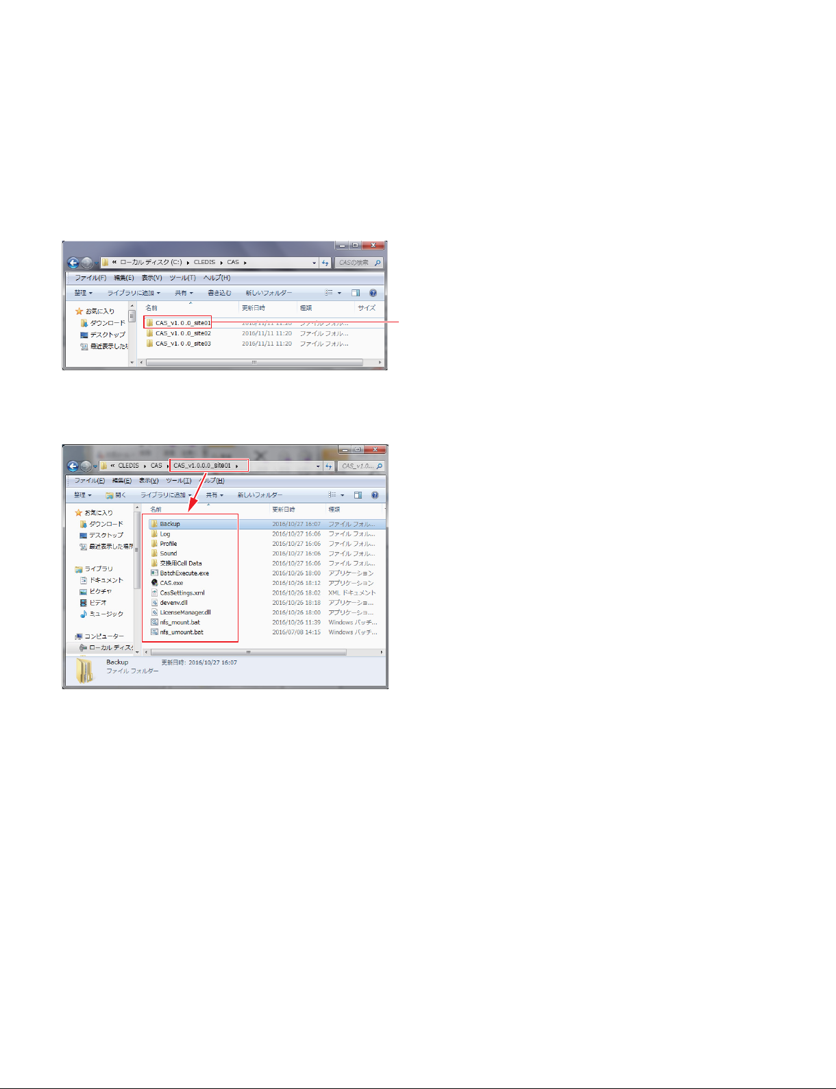
2-10. Storing the Data of Display Unit
Store all data including the [Backup] folder.
The data is necessary in the servicing to maintain the luminance and chromaticity of the array.
In the case that the multiple arrays are operated, add the identification code at the end of a folder name for
storage and management.
Example) “_site01”, “_site02”, “_site03”
Store each folder.
t
The data including the [Backup] folder is stored.
2-12 (E)
CLX101ASA/ZRD-1/ZRD-2/CLF101AKA/ZRCT-100
Page 33
Section 3
Operation in Servicing
3-1. Displaying Error Information and System Information
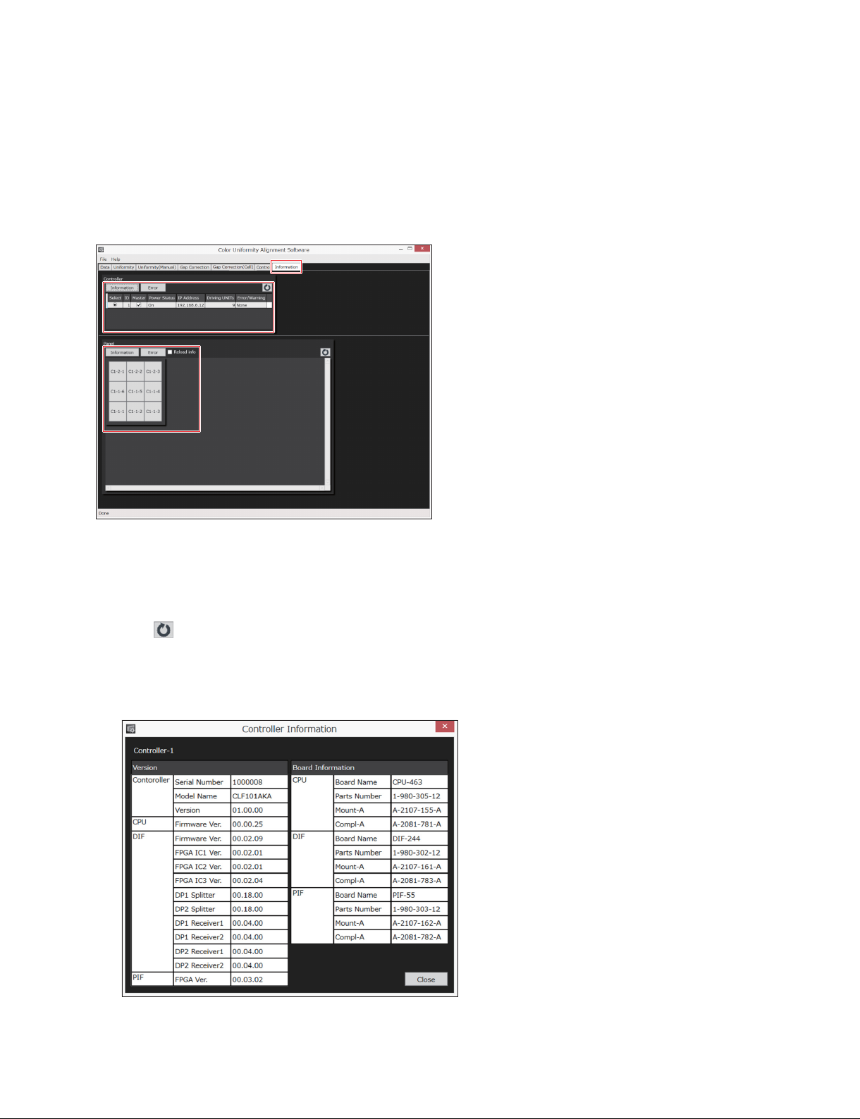
You can see the system information (such as board information and firmware version) and error information of a display controller and a display unit.
The Information screen is used.
3-1-1. Checking Information of Display Controller
1. Click in [Controller].
The list of all display controllers connecting the system is displayed.
2. In the [Select] column, select the display controller that you want to check the information.
3. To check the system information, click [Information].
The board information and the firmware version are displayed.
CLX101ASA/ZRD-1/ZRD-2/CLF101AKA/ZRCT-100
3-1 (E)
Page 34
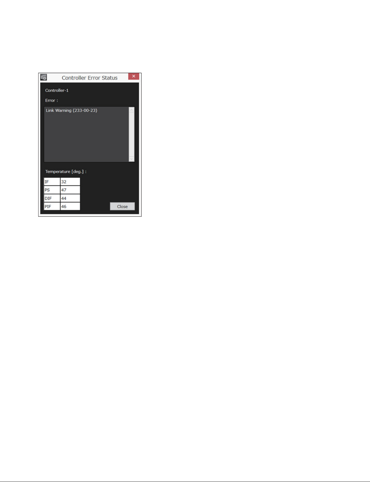
4. To check the error information, click [Error].
The error information is displayed.
For details of the error code, refer to the Service Manual of the display controller.
5. Click [Close].
3-2 (E)
CLX101ASA/ZRD-1/ZRD-2/CLF101AKA/ZRCT-100
Page 35
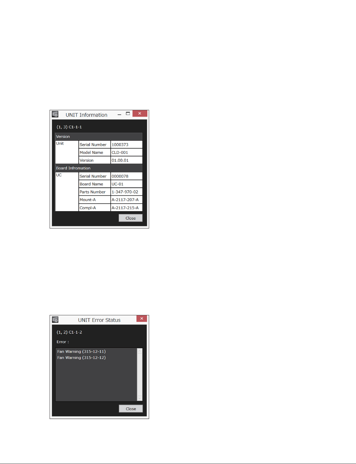
3-1-2. Checking Information of Display Unit
In [Panel], a map of the display units connecting to the system is displayed. An error display unit is indicated in red. A warning display unit is indicated in yellow.
1. Click the display unit that you want to check the information.
2. To check the system information, click [Information].
The board information and the firmware version are displayed.
In the case that [Information] is grayed out
It shows that the board information is not stored as the backup data. Place a check mark in [Reload
info]. The information of all display units is read from the display controller. The reading of the data
takes approximately 10 seconds per display unit. The reading time increases as the number of display
units increases.
3. To check the error information, Click [Error].
The error information is displayed.
For details of the error code, refer to the Service Manual of the display unit.
4. Click [Close].
CLX101ASA/ZRD-1/ZRD-2/CLF101AKA/ZRCT-100
3-3 (E)
Page 36
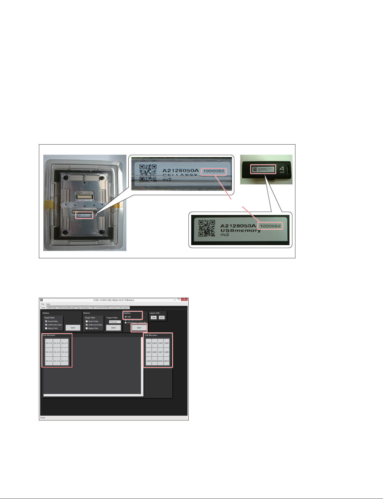
3-2. Operations in Replacing Cell Assembly
For the replacement procedure of a cell assembly, refer to the Service Manual of the display unit.
After replacing the cell assembly, adjust the uniformity in the following procedure.
For the required items for the uniformity adjustment, refer to Section 2-1-1.
3-2-1. Reading Data in a USB Memory
1. Check that the serial number indicated on a USB memory supplied with the cell assembly (RP)
matches with the serial number indicated on the rear of the cell assembly (RP).
Serial number
2. Insert the USB memory to the PC.
3. Start the Color Uniformity Alignment Software. (Refer to Section 1-2.)
4. On [Replace] in the Data screen, click [Cell].
5. Click the display units with replaced cell in [Unit Allocation].
The color of the specified display unit changes to blue on the map.
6. Click the replaced cell in [Cell Allocation].
The color of the specified cell changes to blue on the map.
7. Click [Start] of [Replace].
3-4 (E)
CLX101ASA/ZRD-1/ZRD-2/CLF101AKA/ZRCT-100
Page 37
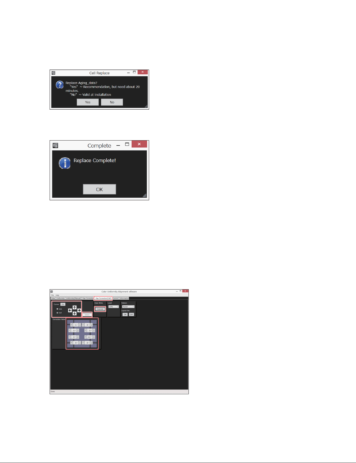
8. Select the file of the USB memory, and then click [Open].
The data in the USB memory is read.
In the process of the reading, the following dialog is displayed. Click [Yes].
When the reading of the file is completed, the following dialog is displayed. A raster image (a white
screen) is displayed in the array.
9. Adjust the uniformity of the cell. (Refer to “2-9. Adjusting Cell with Unevenness Separately”.)
3-2-2. Gap Correction of Cell (Version 1.10 and Later)
If there is any conspicuous joint (seam) between the cells after replacement of a cell assembly, correct the
joint using the Gap Correction (Cell) function.
1. Click the [Gap Correction(Cell)] tab.
The Gap Correction(Cell) screen is displayed.
2. In [Pattern], select a test pattern to be output.
3. In [Level], select a luminance of the array in the correction as required. The default setting is 20%.
CLX101ASA/ZRD-1/ZRD-2/CLF101AKA/ZRCT-100
3-5 (E)
Page 38

4. Select the correction point in the following procedures.
(1) Select [Unit] in [Cursor], and then click [On] in [Cursor].
A cursor by display unit is displayed on the screen.
(2) Shift the cursor to the display unit including the cell that you want to correct using the arrow
keys.
(3) Select [Cell] in [Cursor].
A cursor by cell is displayed on the screen.
(4) Shift the cursor to the cell that you want to correct using the arrow keys.
t
The cursor shifts within a display unit. The cursor cannot shift to the cell in another display unit.
5. Click [Select].
The cursor is cleared.
t
To see which cell is selected, click [On] in [Cursor] again. To clear the cursor, click [Select] again.
6. Change the correction value (_12 to +12) displayed in [Correct Value]. Default: 0 (no correction)
When you select the setting value in the pull-down or when you set it by the arrow keys, the setting
value is transmitted to the array. In the arrow keys, the setting value is transmitted every time you
press the arrow key.
7. When the setting is completed, click [Execute] in [Data Write].
The setting data is written in the display controller.
n
You cannot write the setting data of multiple cells at the same time. Even if you want to correct the
multiple cells, repeat the setting and [Execute] for each cell.
3-6 (E)
CLX101ASA/ZRD-1/ZRD-2/CLF101AKA/ZRCT-100
Page 39

3-3. Operations in Replacing UC Board
Before replacing a UC board in the display unit, perform the following operations.
1. Start the Color Uniformity Alignment Software. (Refer to Section 1-2.)
2. On [Replace] in the Data screen, click [UC Board (Unit)].
3. Click the display units with replaced UC board in [Unit Allocation].
The color of the specified display unit changes to blue on the map.
4. Click [Start] of [Replace].
5. Hereafter, operate in accordance with the instructions in the dialog.
By operating in accordance with the instructions in the dialog, the data is read before replacing the
board, and then the data is written after replacing the board. In the process of the operations, the
instruction to replace the UC board is displayed on the PC. For the replacement procedure of UC
board, refer to the Service Manual of the display unit.
In the case that there is unevenness on the array
Adjust the uniformity of a display unit or a cell with unevenness separately. (Refer to Section 2-8 and
Section 2-9.)
CLX101ASA/ZRD-1/ZRD-2/CLF101AKA/ZRCT-100
3-7 (E)
Page 40
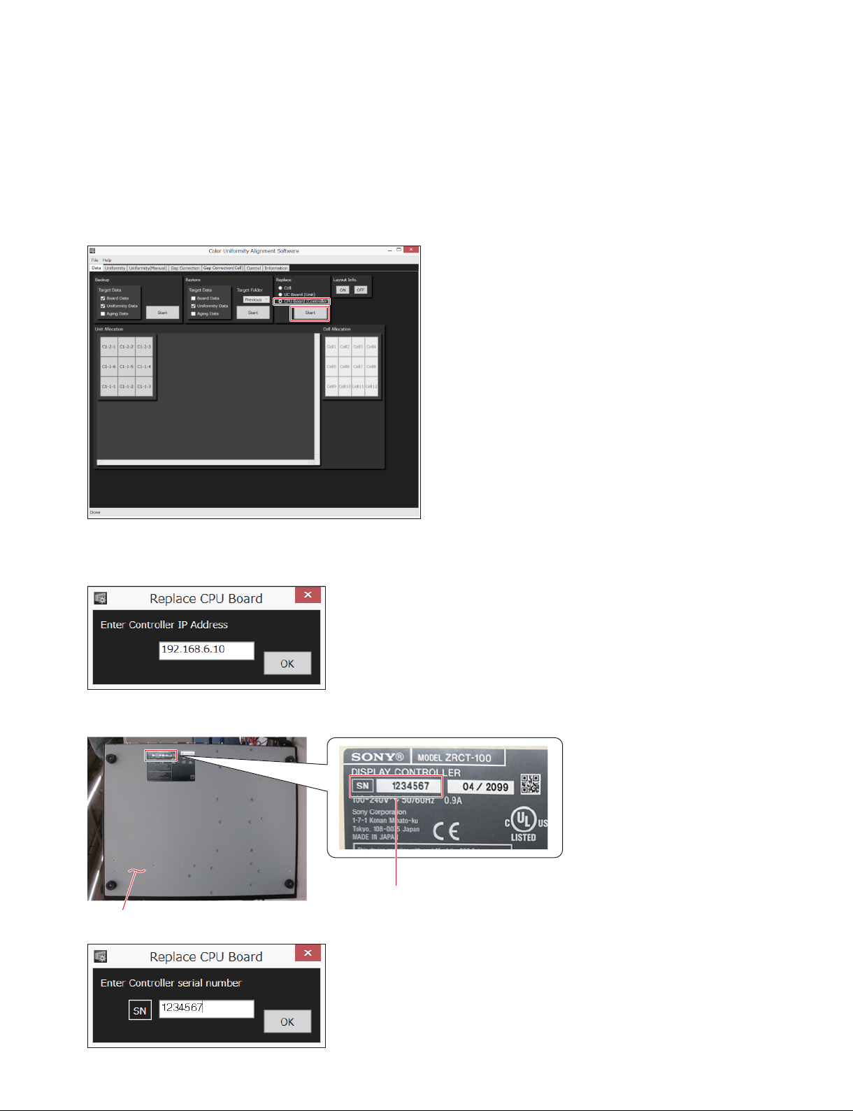
3-4. Operations in Replacing CPU Board
After you replace the CPU board of a display controller, write the serial number of the display controller
to the CPU board.
1. Start the Color Uniformity Alignment Software. (Refer to Section 1-2.)
2. On [Replace] in the Data screen, click [CPU Board (Controller)].
3. Click [Start] of [Replace].
4. Type the IP address, and then click [OK].
5. Type the serial number indicated on the bottom of the display controller, and then click [OK].
Serial number
Bottom of display controller
3-8 (E)
CLX101ASA/ZRD-1/ZRD-2/CLF101AKA/ZRCT-100
Page 41
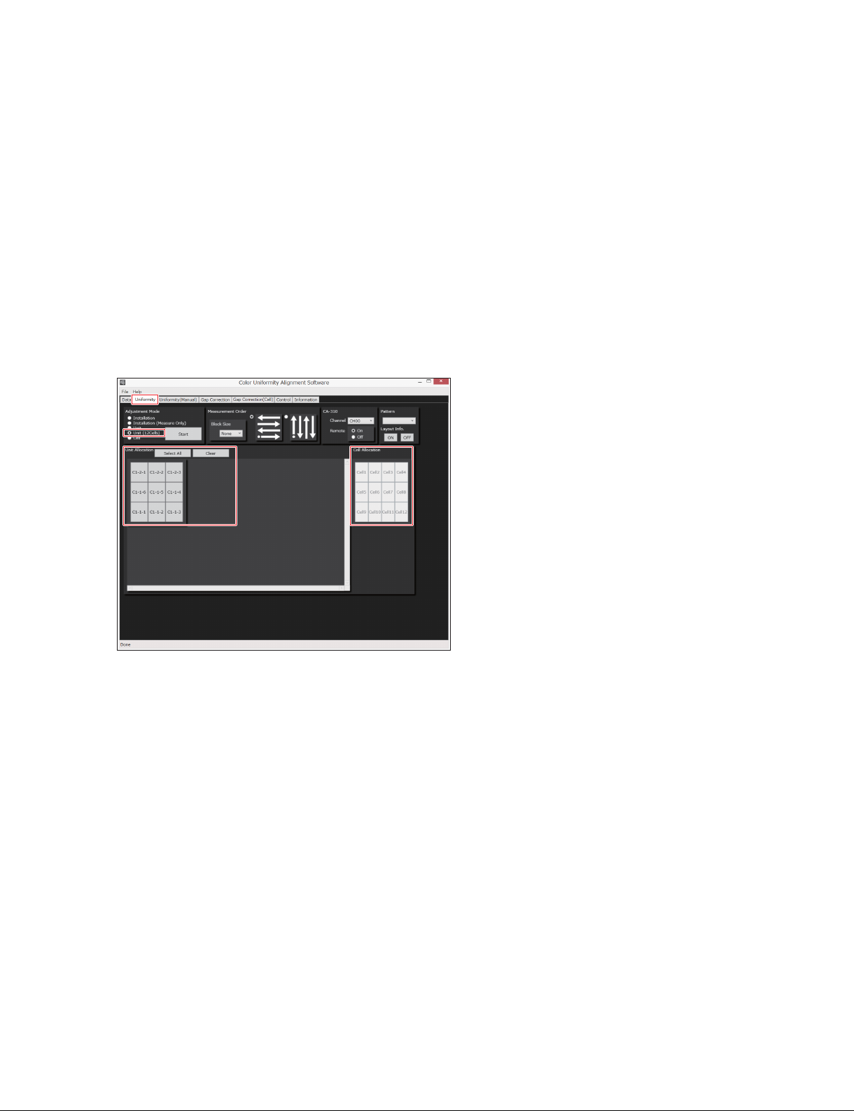
3-5. Adjusting 12 Cells of Display Unit
Adjust the uniformity among the 12 cells of a display unit. After adjusting the luminance and chromaticity
in the display unit, adjust the uniformity to the adjacent display units.
For the required items for the uniformity adjustment, refer to Section 2-1-1.
1. Connect a PC to Display Color Analyzer CA-310. (Refer to Section 2-1-2.)
2. Start the CA-310, and then execute the 0-calcuration. For details on how to operate the 0-calcuration,
refer to an instructions of CA-310.
n
After the 0-calcuration is completed, set the probe to [Measure].
3. Start the Color Uniformity Alignment Software. (Refer to Section 1-2.)
4. Click the [Uniformity] tab.
5. Click [Unit (12Cells)] in [Adjustment Mode].
6. Click the display units that you want to adjust in [Unit Allocation].
You can select the multiple display units.
The color of the specified display unit changes to blue on the map.
t
When [Unit (12Cells)] is selected in [Adjustment Mode], [Cell Allocation] is grayed out. The cell
selection is not necessary because all 12 cells are measured.
7. Adjust the uniformity. (Refer to step 8 to step 11 in “2-4. Uniformity Adjustment”.)
8. Adjust so as to match the display unit to the adjacent display units. (Refer to step 2 to step 4 in “2-8.
Adjusting Display Unit with Unevenness Separately”.)
CLX101ASA/ZRD-1/ZRD-2/CLF101AKA/ZRCT-100
3-9 (E)
Page 42
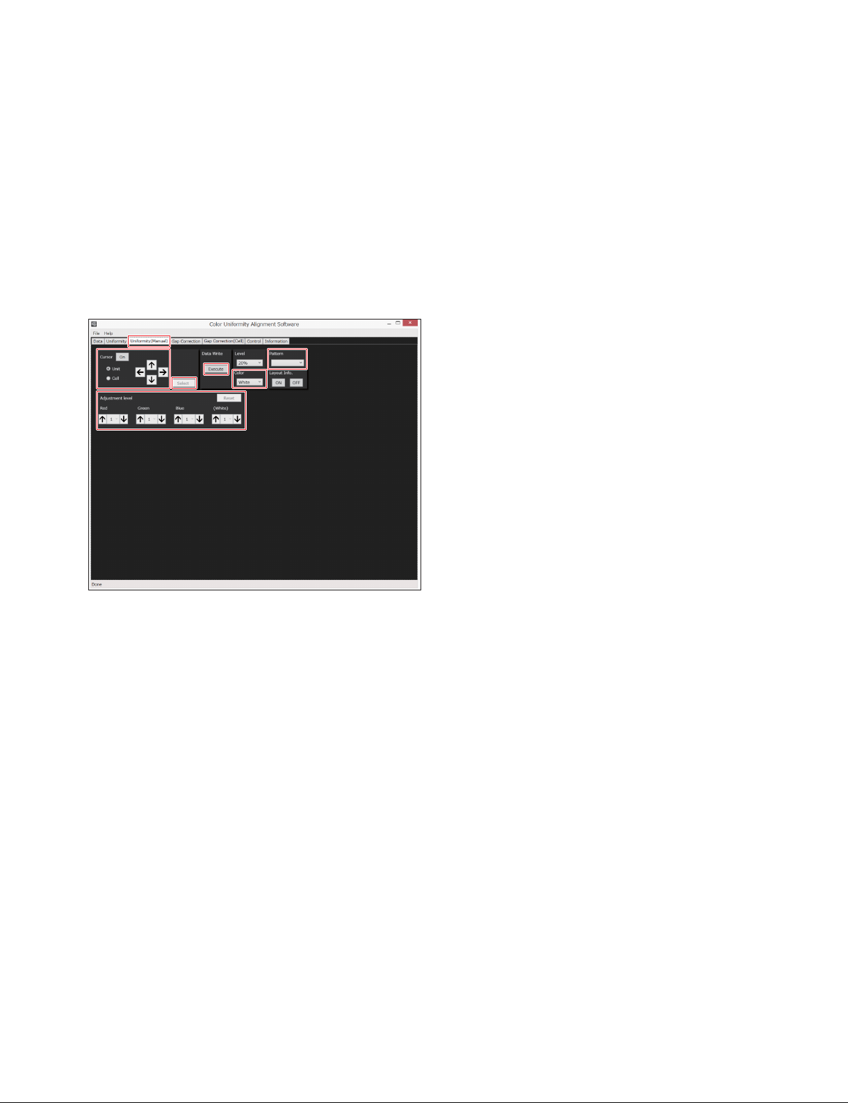
3-6. Visually Adjusting Display Units and Cells (Version 1.10 and Later)
If you have to adjust a display unit and a cell in a hurry, you can adjust them visually without using Digital Color Analyzer.
n
Because of visual adjustment, this adjustment is less precise than the adjustment using Digital Color
Analyzer.
1. Start the Color Uniformity Alignment Software. (Refer to Section 1-2.)
2. Click the [Uniformity (Manual)] tab.
The Uniformity (Manual) screen is displayed.
3. In [Pattern], select a test pattern to be output.
4. In [Level], select a luminance of the array in the adjustment as required. The default setting is 20%.
5. Select the adjustment point in the following procedures.
(1) Select [Unit] in [Cursor], and then click [On] in [Cursor].
A cursor by display unit is displayed on the screen.
(2) Shift the cursor to the display unit that you want to adjust using the arrow keys.
When you want to adjust the display unit, step (3) and step (4) are unnecessary. Proceed to step 6.
(3) When you want to adjust a cell, select [Cell] in [Cursor] after the cursor reaches the display unit
to be adjusted in step (1) and step (2).
A cursor by cell is displayed on the screen.
(4) Shift the cursor to the cell that you want to adjust using the arrow keys.
t
The cursor shifts within a display unit. The cursor cannot shift to the cell in another display unit.
6. Click [Select].
The cursor is cleared.
t
To see which display unit or the cell is selected, click [On] in [Cursor] again. To clear the cursor, click
[Select] again.
7. Select [Red] in [Color].
8. Adjust a luminance of the display unit or the cell using the arrow keys of [Red] in [Adjustment level].
You can select a step from five levels of [1] (0.5%) to [5] (2.5%) for each grade of change by 0.5%.
3-10 (E)
CLX101ASA/ZRD-1/ZRD-2/CLF101AKA/ZRCT-100
Page 43
9. Select [Green] in [Color].
10. Adjust a luminance of the display unit or the cell using the arrow keys of [Green] in [Adjustment
level].
You can select a step from five levels of [1] (0.5%) to [5] (2.5%) for each grade of change by 0.5%.
11. Select [Blue] in [Color].
12. Adjust a luminance of the display unit or the cell using the arrow keys of [Blue] in [Adjustment
level].
You can select a step from five levels of [1] (0.5%) to [5] (2.5%) for each grade of change by 0.5%.
13. Select [White] in [Color].
14. If the color does not match with the adjacent display units or cells, adjust the luminance of the display
unit or the cell using the arrow keys of each color.
You can select a step from five levels of [1] (0.5%) to [5] (2.5%) for each grade of change by 0.5%.
Color of the display unit or the cell How to adjust
Red Lower the luminance in [Red].
Green Lower the luminance in [Green].
Blue Lower the luminance in [Blue].
Cyan Increase the luminance in [Red].
Magenta Increase the luminance in [Green].
Yellow Increase the luminance in [Blue].
To return the luminance to the level before adjustment
Click [Reset].
15. After the colors of the display unit or the cell match to that of the adjacent display units or cells on a
white screen, adjust the luminance of the display unit or the cell using the arrow keys of [White] in
[Adjustment level].
You can select a step from five levels of [1] (0.5%) to [5] (2.5%) for each grade of change by 0.5%.
When you change in [White], the colors of red, green, and blue change simultaneously in the same
step.
16. If you have another display unit or cell to be adjusted, repeat step5 through step 15.
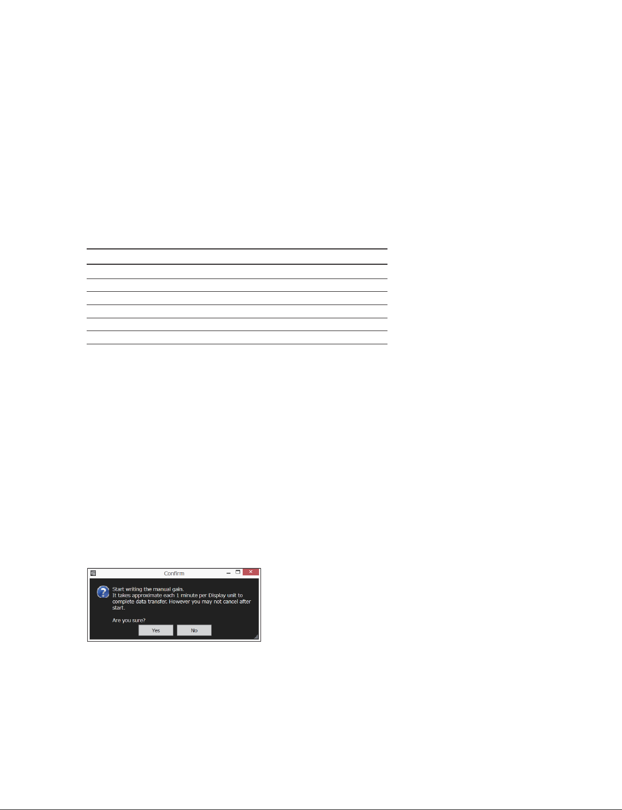
17. When the adjustment is completed, click [Execute].
The following dialog is displayed.
n
The writing takes approximately 1 minute per display unit. The writing time increases as the number
of display units that are changed increases.
CLX101ASA/ZRD-1/ZRD-2/CLF101AKA/ZRCT-100
3-11 (E)
Page 44
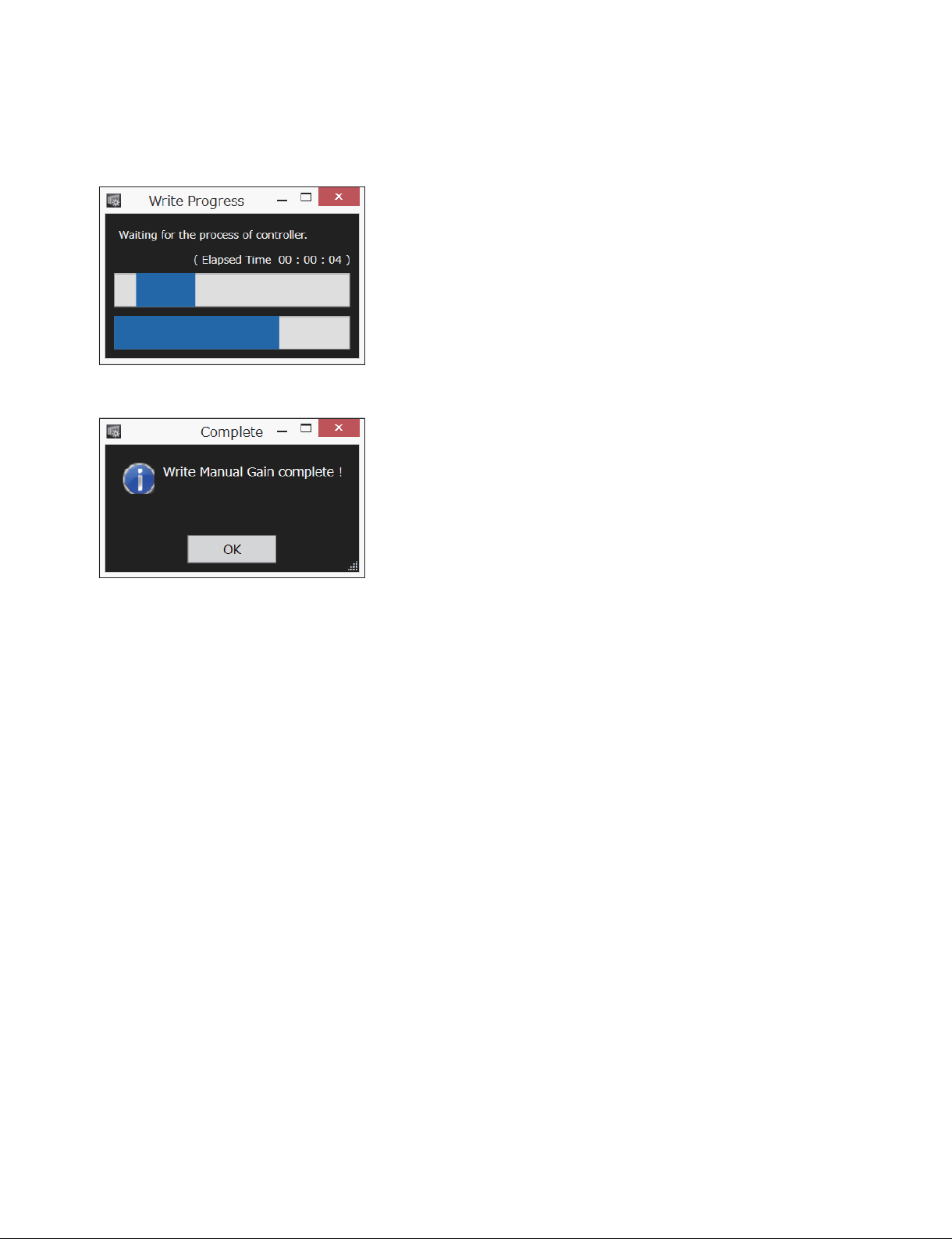
18. Click [Yes].
The following dialog is displayed.
The data of all the display units or all the cells that is changed is written in the display unit.
When the writing is completed, the following dialog is displayed.
19. Click [OK].
The display returns to the Uniformity (Manual) screen.
To display the unit layout address of the display units on the array
Click [ON] in [Layout Info.]. To clear the unit layout address, click [OFF].
For the details on the display, refer to “6 Layout Info.” in “1-3-1. Data Screen”.
3-12 (E)
CLX101ASA/ZRD-1/ZRD-2/CLF101AKA/ZRCT-100
Page 45
Revision History
Date History Contents
2016. 11 1st Edition
9-932-530-01
2017. 5 Revised 1
9-932-530-02
2017. 9 Revised 2
9-932-530-03
―
Added the information on version 1.10.
Modified the all screenshots.
. Modifications:
1-1-2. Connection
1-2. Starting Color Uniformity Alignment Software
1-3. Features of Screen
2-1-2. Connection
2-3. Backing Up the Data
2-4. Uniformity Adjustment
2-5. Joint Correction (Gap Correction)
2-6. Only Measuring Luminance and Chromaticity
2-7. Restoring Measurement Data
2-8. Adjusting Display Unit with Unevenness Separately
2-9. Adjusting Cell with Unevenness Separately
3. Operation in Servicing
. Additions:
1-3-3. Uniformity (Manual) Screen (Version 1.10 and Later)
3-6. Visually Adjusting Display Units and Cells (Version 1.10 and Later)
Added the models: CLX101ASA, ZRD-2, and CLF101AKA
Added the feature of Gap Correction (Cell).
Modified the screenshots.
. Modifications:
1-1-3. Installing Color Uniformity Alignment Software
1-1-4. Setting NFS (Network File System)
1-2. Starting Color Uniformity Alignment Software
1-3. Features of Screen
2-1-1. Required Items
2-3. Backing Up the Data
2-4. Uniformity Adjustment
2-5. Joint Correction (Gap Correction)
2-7. Restoring Measurement Data
3. Operation in Servicing
. Additions:
1-3-5. Gap Correction (Cell) Screen (Version 1.10 and Later)
3-2-2. Gap Correction of Cell (Version 1.10 and Later)
CLX101ASA/ZRD-1/ZRD-2/CLF101AKA/ZRCT-100
i
Page 46

Page 47

Page 48

CLX101ASA (SY)
CLX101ASA (CN)
ZRD-1 (SY)
ZRD-1 (CN)
ZRD-2 (SY)
ZRD-2 (CN)
CLF101AKA (SY)
CLF101AKA (CN)
ZRCT-100 (SY)
ZRCT-100 (CN) J, E
9-932-530-03
Sony Corporation
Printed in Japan
2017. 9 32
©2016
 Loading...