

Sony CFD-S36 Service manual
CFD-S36
SERVICE MANUAL
Ver 1.0 2001. 01
Photo: White
CD
Section
TC
Section
US Model
Model Name Using Similar Mechanism CFD-S32
CD Mechanism Type KSM-213CDP
Optical Pick-up Name KSS-213C
Model Name Using Similar Mechanism CFD-V5
Tape Transport Mechanism Type MF-V5-117
AUDIO POWER SPECIFICATIONS
POWER OUTPUT AND TOTAL
HARMONIC DISTORTION
With 3.2-ohm loads, both channels driven from
150 - 6,300 Hz; rated 1.8 W per channelminimum RMS power, with no more than 10%
total harmonic distortion in AC operation.
Other Specifications
CD player section
System
Compact disc digital audio system
Laser diode properties
Material: GaAlAs
Wave length: 780 nm
Emission duration: Continuous
Laser output: Less than 44.6 µW
(This output is the value measured at a distance of
about 200 mm from the objective lens surface on
the optical pick-up block with 7 mm aperture.)
Spindle speed
200 r/min (rpm) to 500 r/min (rpm) (CLV)
Number of channels
2
Frequency response
20 - 20,000 Hz +1/–2 dB
Wow and flutter
Below measurable limit
SPECIFICATIONS
Radio section
Frequency range
FM: 87.6 - 108 MHz
AM: 530 - 1,710 kHz
TV: 2 - 13 CH
WEATHER: 1 - 7 CH
Antennas
FM/TV/WEATHER: Telescopic antennas
AM: Built-in ferrite bar antennas
Cassette-corder section
Recording system
4-track 2 channel stereo
Fast winding time
Approx. 120 sec. with Sony cassette C-60
Frequency response
TYPE I (normal): 80 - 10,000 Hz
General
Speaker
Full range: 10 cm dia.,
3.2 ohms, cone type (2)
Outputs
Headphones jack (stereo minijack)
For 16 - 68 ohms impedance headphones
– Continued on next page –
9-873-061-11
2001A0400-1
© 2001. 1
CD RADIO CASSETTE-CORDER
Sony Corporation
Audio Entertainment Group
General Engineering Dept.
1

CFD-S36
Power output
2.3 W + 2.3 W (at 3.2 ohms, 10 %
harmonic distortion in AC operation)
Power requirements
For CD radio cassette-corder:
120 V AC, 60 Hz
9 V DC, 6 size D (R20) batteries
For remote control
3 V DC, 2 size AA (R6) batteries
Power consumption
AC 20 W
Battery life
For CD radio cassette-corder:
FM recording
Sony R20P: approx. 13.5 h
Sony alkaline LR20: approx. 20 h
Tape playback
Sony R20P: approx. 7.5 h
Sony alkaline LR20: approx. 15 h
CD playback
Sony R20P: approx. 2.5 h
Sony alkaline LR20: approx. 7 h
Dimensions
Approx. 420 × 159 × 284 mm (w/h/d)
5/8 × 6 3/8 × 11 1/4 inches) (incl. projecting parts)
(16
Mass
Approx. 3.8 kg (8 lb. 6 oz.) (incl. batteries)
Supplied accessories
AC power cord (1)
Remote control RMT-CS36WA (1)
Design and specifications are subject to change without
notice.
CAUTION
Use of controls or adjustments or performance of procedures other than those specified herein may result in hazardous radiation exposure.
Flexible Circuit Board Repairing
• Keep the temperature of the soldering iron around 270˚C during
repairing.
• Do not touch the soldering iron on the same conductor of the
circuit board (within 3 times).
• Be careful not to apply force on the conductor when soldering
or unsoldering.
Notes on Chip Component Replacement
• Never reuse a disconnected chip component.
• Notice that the minus side of a tantalum capacitor may be dam-
aged by heat.
NOTES ON HANDLING THE OPTICAL PICK-UP BLOCK
OR BASE UNIT
The laser diode in the optical pick-up block may suffer electrostatic
breakdown because of the potential difference generated by the
charged electrostatic load, etc. on clothing and the human body.
During repair, pay attention to electrostatic breakdown and also use
the procedure in the printed matter which is included in the repair
parts.
The flexible board is easily damaged and should be handled with
care.
NOTES ON LASER DIODE EMISSION CHECK
The laser beam on this model is concentrated so as to be focused on
the disc reflective surface by the objective lens in the optical pickup block. Therefore, when checking the laser diode emission,
observe from more than 30 cm away from the objective lens.
SAFETY-RELATED COMPONENT WARNING!!
COMPONENTS IDENTIFIED BY MARK 0 OR DOTTED LINE
WITH MARK 0 ON THE SCHEMATIC DIAGRAMS AND IN
THE PARTS LIST ARE CRITICAL TO SAFE OPERATION.
REPLACE THESE COMPONENTS WITH SONY PARTS WHOSE
PART NUMBERS APPEAR AS SHOWN IN THIS MANUAL OR
IN SUPPLEMENTS PUBLISHED BY SONY.
2
CFD-S36
SAFETY CHECK-OUT
After correcting the original service problem, perform the following
safety check before releasing the set to the customer:
Check the antenna terminals, metal trim, “metallized” knobs, screws,
and all other exposed metal parts for AC leakage. Check leakage as
described below.
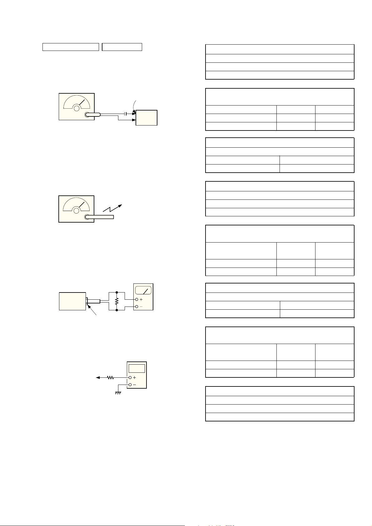
LEAKAGE TEST
The AC leakage from any exposed metal part to earth ground and
from all exposed metal parts to any exposed metal part having a
return to chassis, must not exceed 0.5 mA (500 microamperes).
Leakage current can be measured by any one of three methods.
1. A commercial leakage tester, such as the Simpson 229 or RCA
WT-540A. Follow the manufacturers’ instructions to use these
instruments.
2. A battery-operated AC milliammeter. The Data Precision 245
digital multimeter is suitable for this job.
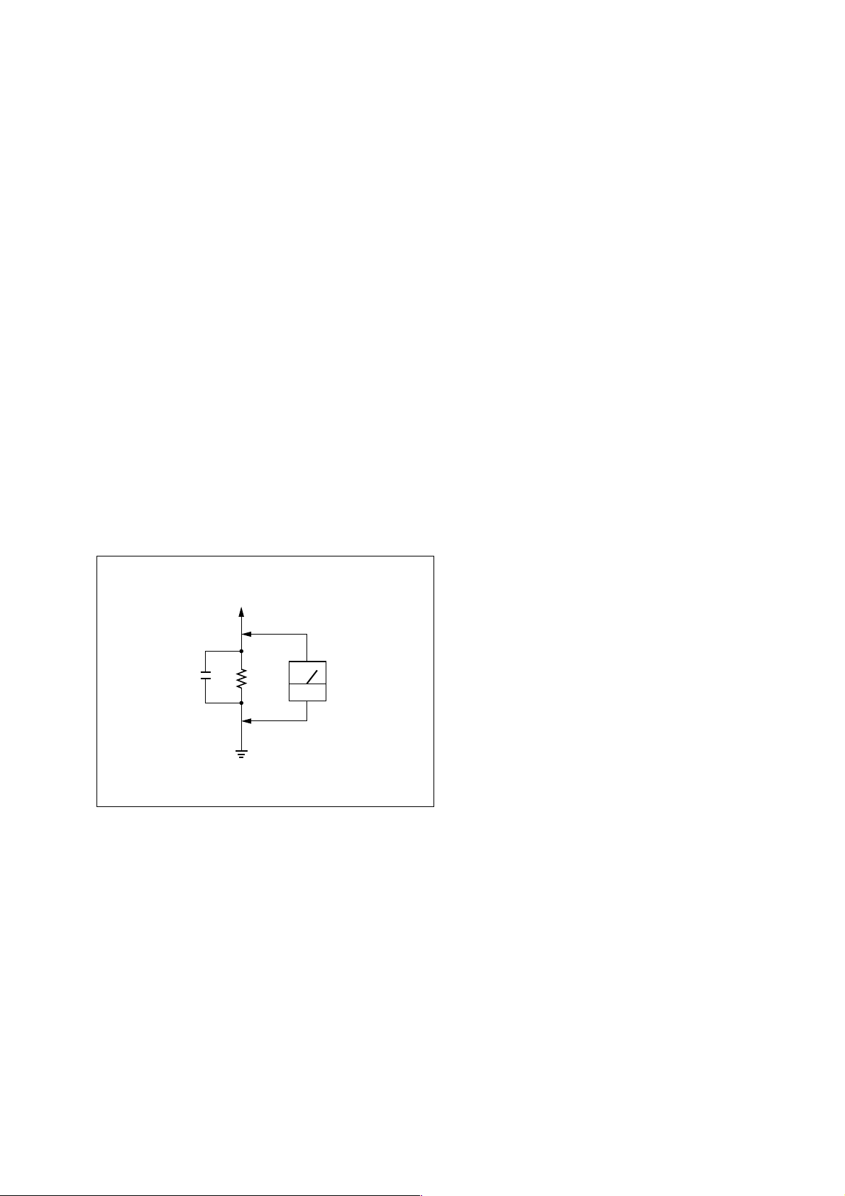
3. Measuring the voltage drop across a resistor by means of a VOM
or battery-operated AC voltmeter. The “limit” indication is 0.75
V, so analog meters must have an accurate low-voltage scale. The
Simpson 250 and Sanwa SH-63Trd are examples of a passive
VOM that is suitable. Nearly all battery operated digital
multimeters that have a 2V AC range are suitable. (See Fig. A)
TABLE OF CONTENTS
1. SERVICING NOTES ......................................................... 4
2. GENERAL
Location of controls ................................................................. 5
3. DISASSEMBLY
3-1. Cabinet (Front) Sub Assy .................................................... 6
3-2. Wires ................................................................................... 7
3-3. Power (1) Board, Power (2) Board...................................... 7
3-4. Cabinet (Upper) Assy .......................................................... 8
3-5. Main Board ......................................................................... 8
3-6. CD Mechanism Block ......................................................... 9
3-7. Tape Mechanism Block ....................................................... 9
3-8. Holder Assy, Cassette ........................................................ 10
3-9. PRE Board ......................................................................... 10
3-10. Belt, M801 (Capstan/Reel Moter),
HRP301 (Head, Magnetic) ................................................ 11
3-11. Optical Pick-up ................................................................. 11
4. MECHANICAL ADJUSTMENTS ............................... 12
5. ELECTRICAL ADJUSTMENTS
Tape Section .......................................................................... 12
Tuner Section......................................................................... 13
CD Section ............................................................................ 14
To Exposed Metal
Parts on Set
0.15µF
1.5k
Ω
Earth Ground
AC
voltmeter
(0.75V)
Fig. A. Using an AC voltmeter to check AC leakage.
6. DIAGRAMS
6-1. IC Pin Description ............................................................. 15
6-2. Circuit Boards Location .................................................... 15
6-3. Block Diagram – CD Section – ......................................... 16
6-4. Block Diagram – Main Section – ...................................... 17
6-5. Printed Wiring Board – CD Section – ............................... 18
6-6. Schematic Diagram – CD Section –.................................. 19
6-7. Printed Wiring Boards – Main Section – .......................... 20
6-8. Schematic Diagram – Main Section (1/4) – ...................... 21
6-9. Schematic Diagram – Main Section (2/4) – ...................... 22
6-10. Schematic Diagram – Main Section (3/4) – ...................... 23
6-11. Schematic Diagram – Main Section (4/4) – ...................... 24
6-12. Printed Wiring Boards – Control Section – ....................... 25
6-13. Schematic Diagrams – Control Section – ......................... 26
6-14. Printed Wiring Boards – Power Supply Section – ............ 27
6-15. Schematic Diagrams – Power Supply Section – ............... 28
7. EXPLODED VIEWS
7-1. Cabinet (Front) Section ..................................................... 32
7-2. Cabinet (Rear) Section ...................................................... 33
7-3. Cabinet (Upper) Section .................................................... 34
7-4. Tape Mechanism Section-1 ............................................... 35
7-5. Tape Mechanism Section-2 ............................................... 36
7-6. Optical Pick-up Section .................................................... 37
8. ELECTRICAL PARTS LIST......................................... 38
3
CFD-S36
SECTION 1
SERVICING NOTES
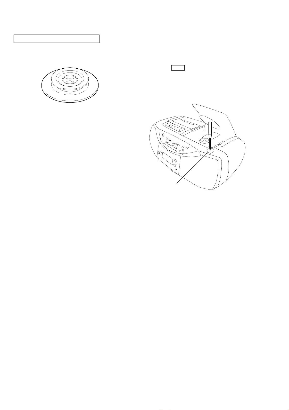
CHUCK PLATE JIG ON REPAIRING
On repairing CD section, playing a disc without the lid (CD), use
Chuck Plate Jig.
• Code number of Chuck Plate Jig: X-4918-255-1
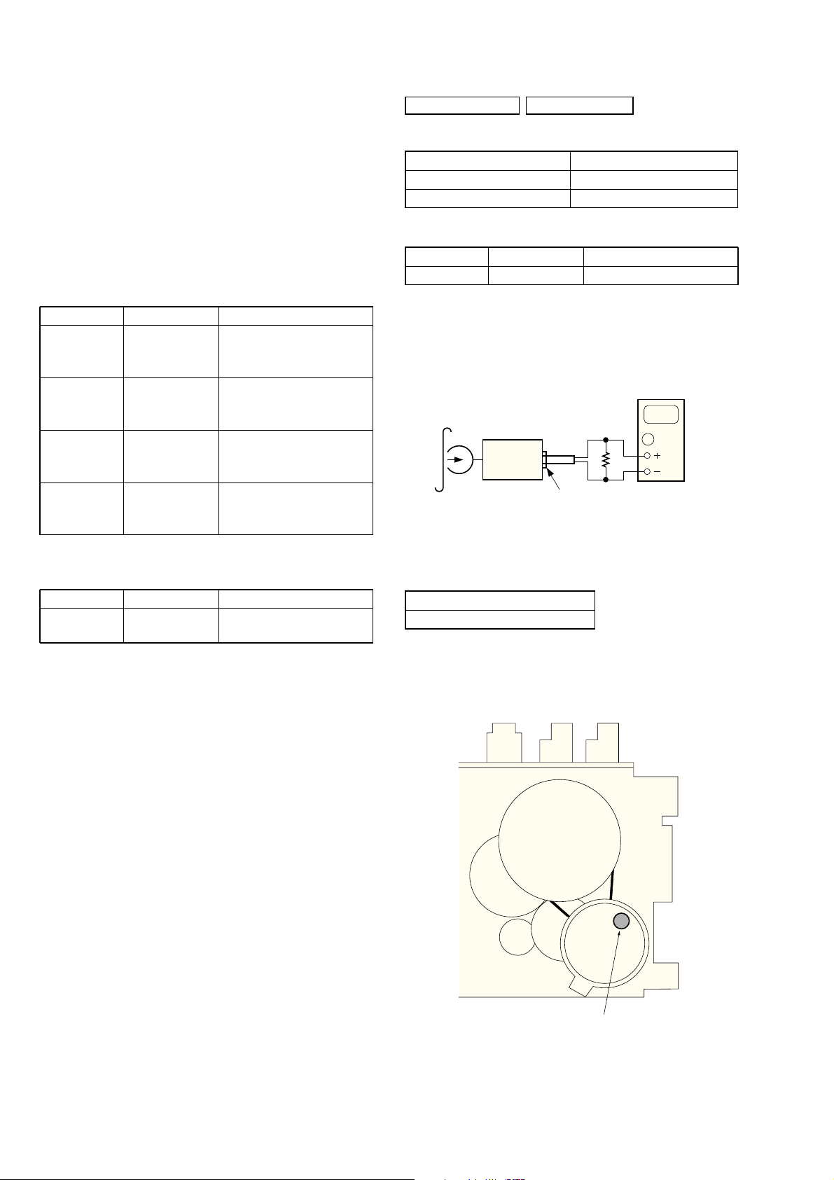
LASER DIODE AND FOCUS SEARCH OPERATION
CHECK
1. Turn ON the POWER button and press FUNCTION button to
CD position.
2. Open the lid (CD).
3. Turn on S801 with screwdriver, etc. as following figure.
4. Press the CD N X button.
5. Confirm the laser diode emission while observing the objecting
lens. When there is no emission, Auto Power Control circuit or
Optical Pick-up is broken.
Objective lens moves up and down three times for focus search.
S801
4
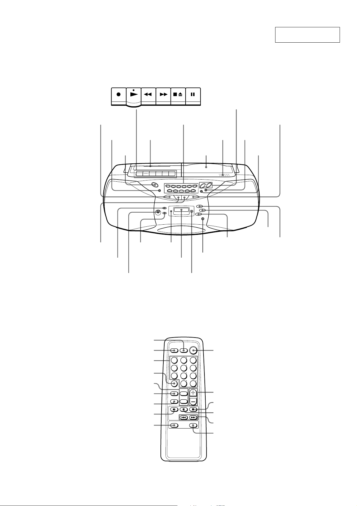
Location of controls
SECTION 2
GENERAL
CFD-S36
This section is extracted
from instruction manual.
REC PLAY REW FF
N X
Tape
SLEEP
POWER
TUNE –, +
.,>
DISPLAY ENT
MEMORY
i (headphones) jack
Tip
To listen through headphones, connect the headphones to the i (headphones) jack.
compartment
MODE
STOP/EJECT
PAUSE
Number buttons for
CD/RADIO DIRECT OPERATION
Z PUSH
OPEN/CLOSE
CD
compartment
OPR/BATT
indicator
Display
WEATHER
(CFD-S36 US model only)
Remote sensor
(CFD-S36 only)
VOLUME +,–
RADIO BAND
AUTO PRESET
x
MEGA Xpand
(CFD-S36 only)
MEGA BASS
TAPE
CD
Remote Control (CFD-S36 only)
SLEEP
FUNCTION
Number buttons
MODE
TUNE +,–
BAND
WEATHER
(US model only)
N
MEGA Xpand
POWER
VOL +,–
x
X
.,>
MEGA BASS
5
CFD-S36
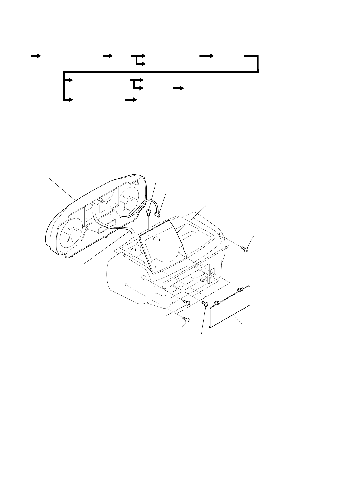
SECTION 3
DISASSEMBLY
• The equipment can be removed using the following procedure.
Set Cabinet (Front) Sub Assy Wires
Tape Mechanism Block
CD Mechanism Block
Note : Follow the disassembly procedure in the numerical order given.
Cabinet (Upper) Assy
Power (1) Board, Power (2) Board
Holder Assy, Cassette
PRE Board
Optical Pick-up
3-1. CABINET (FRONT) SUB ASSY
9 cabinet (front) sub assy
6 BVTP 3x12
7 CNP323
Main Board
Belt,M801(Capstan/Reel Motor),
HRP301 (Head, Magnetic)
lid (CD)
8 CNP805
2 BVTP 3x10
3 BVTP 3x10
1 lid, battery case
4 BVTP 3x12
5 BVTP 3x10
6
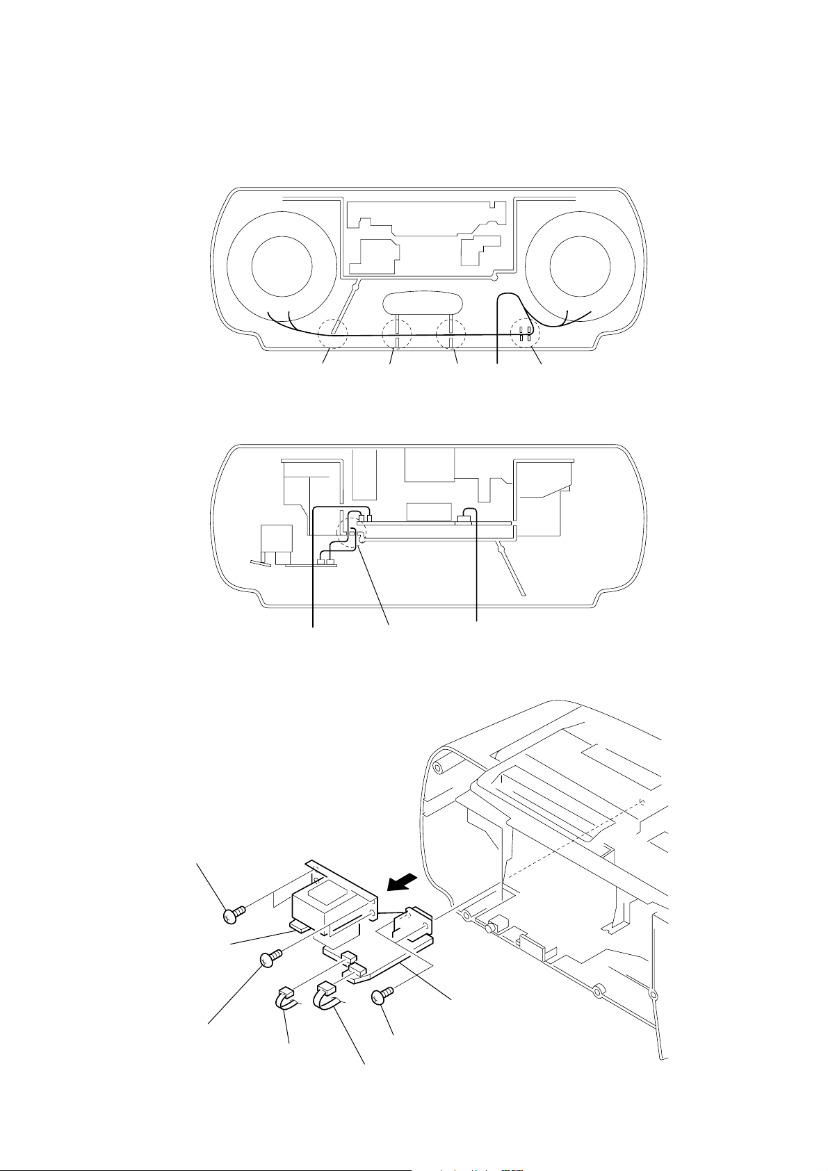
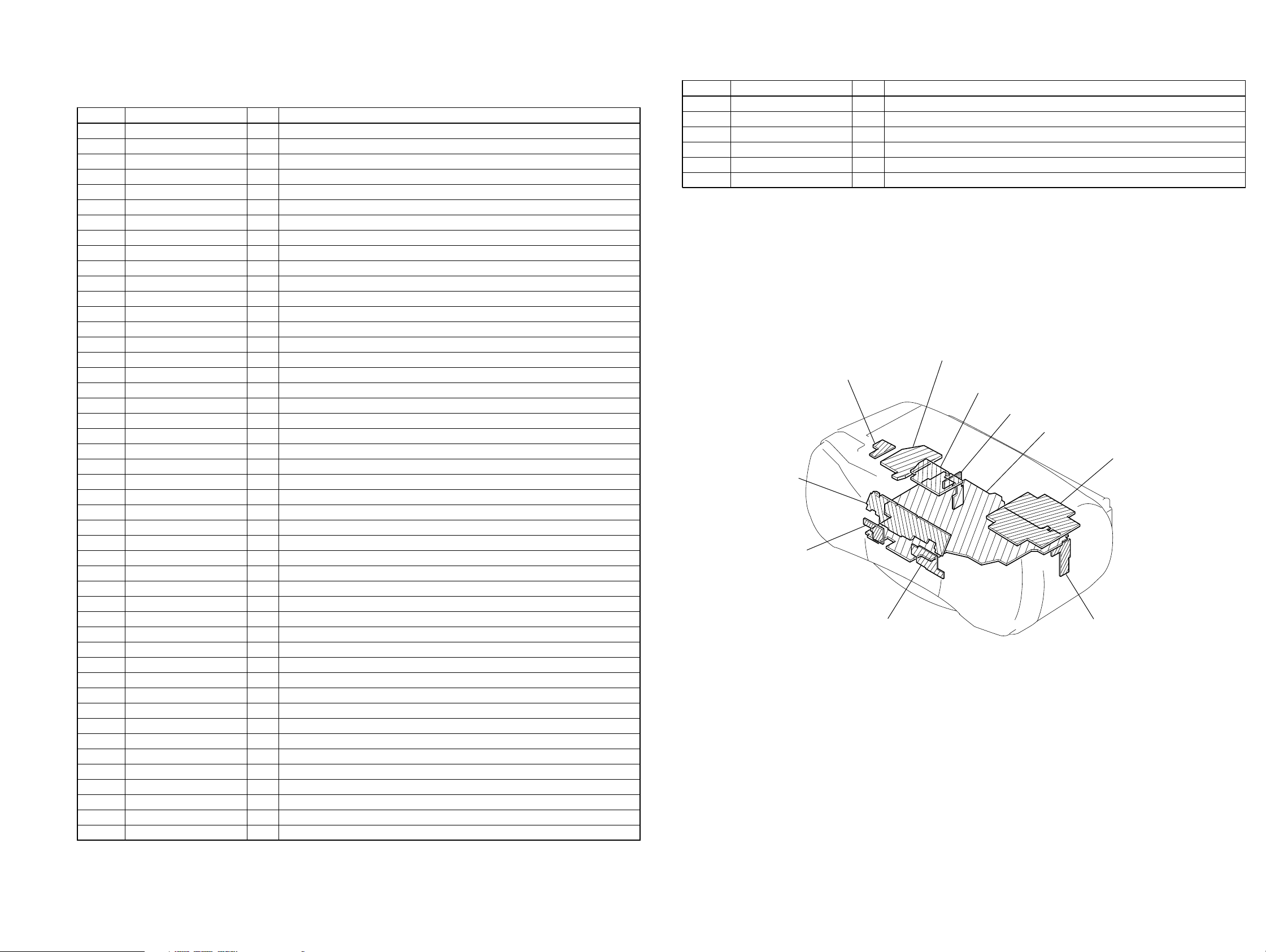
3-2. WIRES
)
Put flat cable and wires between the cabinets and push them in the
grooves located at A to E in the figure to prevent disconnection
before assembling the set.
CFD-S36
CABINET (FRONT
AB
from SP from CONTROL (1) board
3-3. POWER (1) BOARD, POWER (2) BOARD
CD
CABINET (REAR)
E
3 BVTP 3x10
POWER (2) board
2 BVTP 3x10
5 CNP901
4
7 POWER (1) board
1 BVTP 3x10
6 CNP902
7
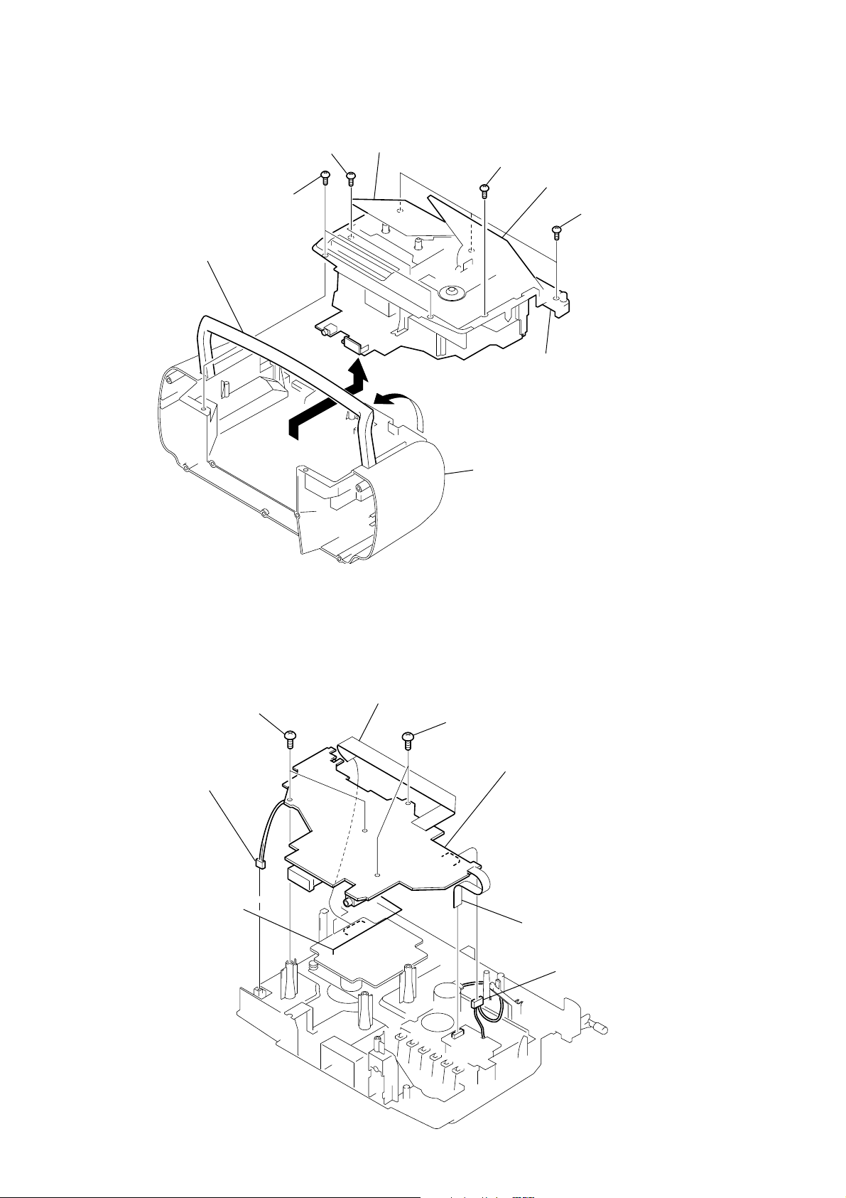
CFD-S36
y
2
3-4. CABINET (UPPER) ASSY
1 BVTP 3x10
7 handle
4 BVTP 3x12
3 holder assy, cassette
6 BVTP 3x12
5 lid (CD)
2 BVTP 3x12
8 cabinet (upper) ass
cabinet (rear)
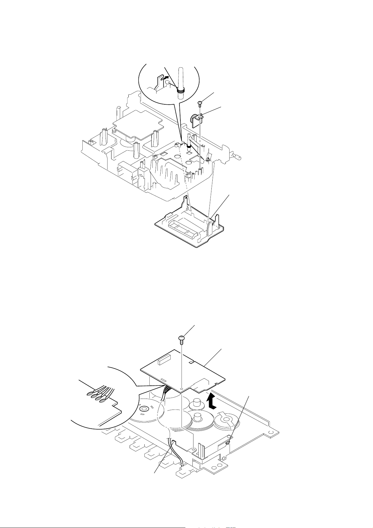
3-5. MAIN BOARD
1 terminal, antenna
6 BVTP 3x10
2 connector
(S801)
3 CNP702
5 BVTP 3x10
8 MAIN board
7 CN303
4 CNP30
8
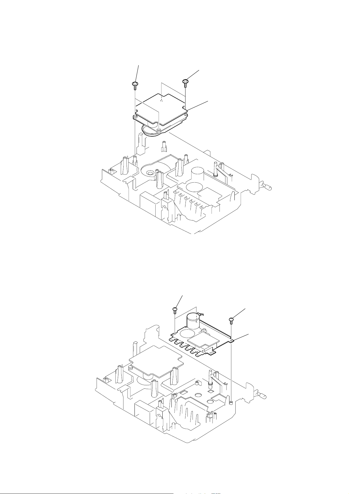
3-6. CD MECHANISM BLOCK
k
CFD-S36
1 PWH 2.6x10
2 PWH 2.6x10
3 CD mechanism block
(KSM-213CDP)
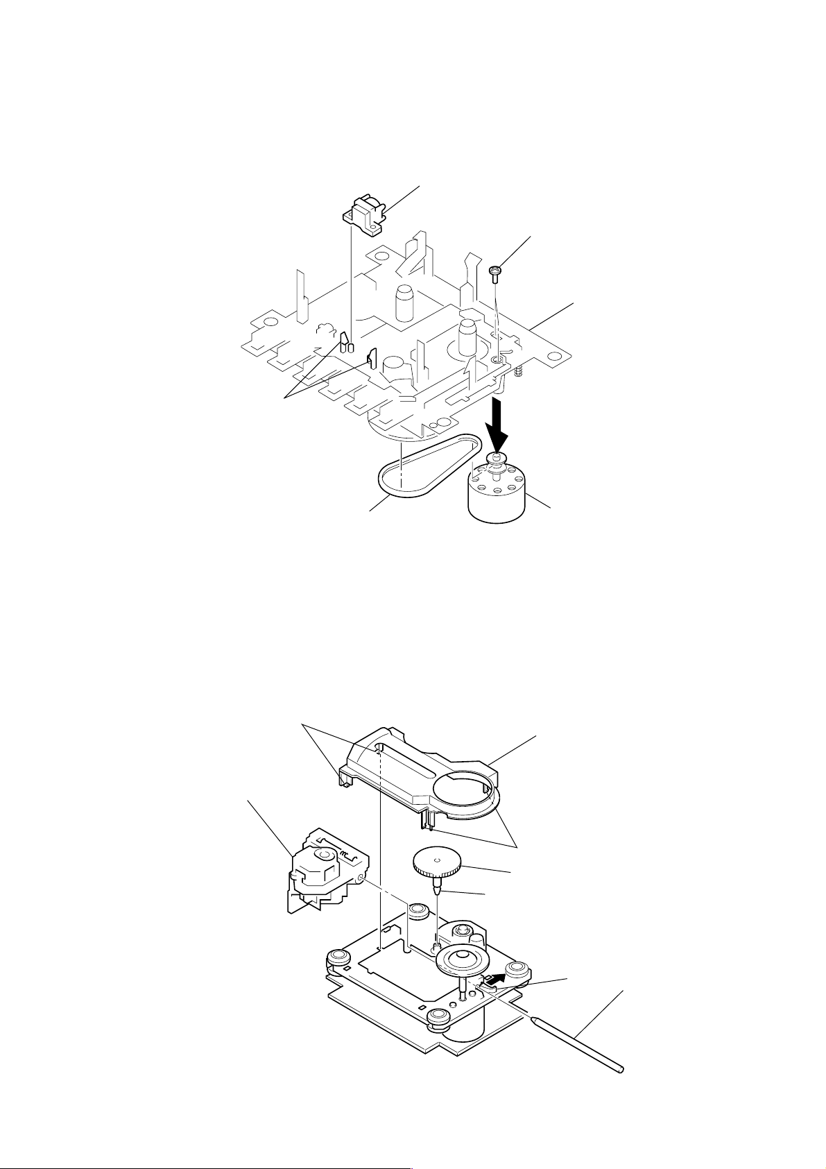
3-7. TAPE MECHANISM BLOCK
1 BVTP 3x10
2 BVTP 3x10
3 tape mechanism bloc
(MF-V5-117)
9
CFD-S36
3-8. HOLDER ASSY, CASSETTE
3
1 BVTP 3x10
2 DAMPER
4 holder assy, cassette
3-9. PRE BOARD
3 Removal the solders.
1 BVTT 2x6
4 PRE board
claw
2
10
claw
)
3-10. BELT, M801 (CAPSTAN/REEL MOTOR), HRP301 (HEAD, MAGNETIC)
6 HRP301 (head, magnetic)
1 screws
B 2.6 × 5
mechanism deck
5 claws
2
CFD-S36
3-11. OPTICAL PICK-UP
9 optical pick-up
2 claws
3 belt
4 M801
(capstan/reel motor
3 cover, CD
1 claws
5 gear (A)
4 claw
7
6 claw
8 sled shaft
11
CFD-S36
)
SECTION 4
MECHANICAL ADJUSTMENTS
SECTION 5
ELECTRICAL ADJUSTMENTS
PRECAUTION
1. Clean the following parts with a denatured-alcohol-moistened
swab :
record/playback head pinch roller
erase head rubber belts
capstan idlers
2. Demagnetize the record/playback head with a head demagnetizer. (Do not bring the head magnetizer close to the erase head.)
3. Do not use a magnetized screwdriver for the adjustments.
4. The adjustments should be performed with the rated power
supply voltage (9V) unless otherwise noted.
Torque Measurement
Mode Torque meter Meter reading
2.95 – 6.86 mN • m
FWD CQ-102C (30 – 70 g • cm)
(0.42 – 0.97 oz • inch)
FWD
Back Tension
FF CQ-201B (more than 60 g • cm)
REW CQ-201B (more than 60 g • cm)
CQ-102C (1.5 – 5.5 g • cm)
0.15 – 0.53 mN • m
(0.021 – 0.076 oz • inch)
more than 5.88 mN • m
(more than 0.83 oz • inch)
more than 5.88 mN • m
(more than 0.83 oz • inch)
TAPE SECTION 0 dB = 0.775 V
• Standard Output Level
Output terminal HP OUT
load impedance 32 Ω
output signal level 0.25 V (–10 dB)
• Test Tape
Type Signal Used for
WS-48A 3 kHz, 0 dB tape speed adjustment
Tape Speed Adjustment
Procedure:
Mode: playback
test tape
WS-48A
(3 kHz, 0 dB)
set
i jack (J321
Adjust so that the value on the digital frequency counter is
3,000 Hz.
digital frequency
counter
32 Ω
Tape Tension Measurement
Mode Tension meter Meter Reading
FWD CQ-403A
more than 100 g
(more than 3.53 oz)
Specification Value:
Digital frequency counter
2,940 to 3,060 Hz
Adjust so that the frequency at the beginning and that at the end of
tape winding are between 2,970 to 3,030 Hz.
Adjustment Location:
12
Tape speed adjustment
control inside motor
CFD-S36
)
TUNER SECTION 0 dB = 1 µV
• FM Section
Setting:
RADIO (BAND) button: FM
FM RF signal
generator
TP (JW1)
0.01 µF
set
75 kHz frequency
deviation by 1 kHz signal
output level : as low as possible
• AM Section
Setting:
RADIO (BAND) button: AM
AM RF signal
generator
Put the lead-wire
antenna close to
the set.
30% amplitude
modulation by
400 Hz signal
• Connecting Level Meter (FM/TV/WB and AM)
level meter
(range: 0.5–5 V ac
32 Ω
set
i jack (J321)
AM IF ADJUSTMENT
Adjust for a maximum reading on level meter.
T1
450 kHz (Display: 1,000 kHz)
AM FREQUENCY COVERAGE
ADJUSTMENT
Frequency Display 530 kHz 1,710 kHz
Reading on Digital voltmeter 1.0 ± 0.1 V 5.3 ± 0.7 V
Adjustment Part L6 <confirmation>
AM TRACKING ADJUSTMENT
Adjust for a maximum reading on level meter.
L5 CT5
620 kHz 1,400 kHz
FM/TV IF ADJUSTMENT
Adjust for a maximum reading on level meter.
T2
10.75 MHz (Display: 88 MHz)
TV-H/WB FREQUENCY COVERAGE
ADJUSTMENT
Frequency Display
WB-2h TV-13ch
(162.4 MHz) (215.75 MHz)
Reading on Digital voltmeter 1.2 ± 0.15 V 4.2 ± 0.2 V
Adjustment Part L3 CT4
TV-H/WB TRACKING ADJUSTMENT
Adjust for a maximum reading on level meter.
L1 CT2
TV-7ch (179.75 MHz) TV-11ch (203.75 MHz)
• Connecting Digital Voltmeter (FM/TV/WB and AM)
digital
voltmeter
100 kΩ
TP (JW18)
• Repeat the procedures in each adjustment several times, and the
frequency coverage and tracking adjustments should be finally
done by the trimmer capacitors.
FM/TV-L FREQUENCY COVERAGE
ADJUSTMENT
Frequency Display
TV-2h
(59.75 MHz)
108 MHz
Reading on Digital voltmeter 0.5 ± 0.15 V 4.5 ± 0.2 V
Adjustment Part L4 CT3
FM/TV-L TRACKING ADJUSTMENT
Adjust for a maximum reading on level meter.
L2
TV-5ch (81.75 MHz)
Adjustment Location: See page 14.
13
CFD-S36
TP
(RF)
TP
(VREF)
TP
(RF)
TP
(VREF)
– CD board (conductor side) –
T
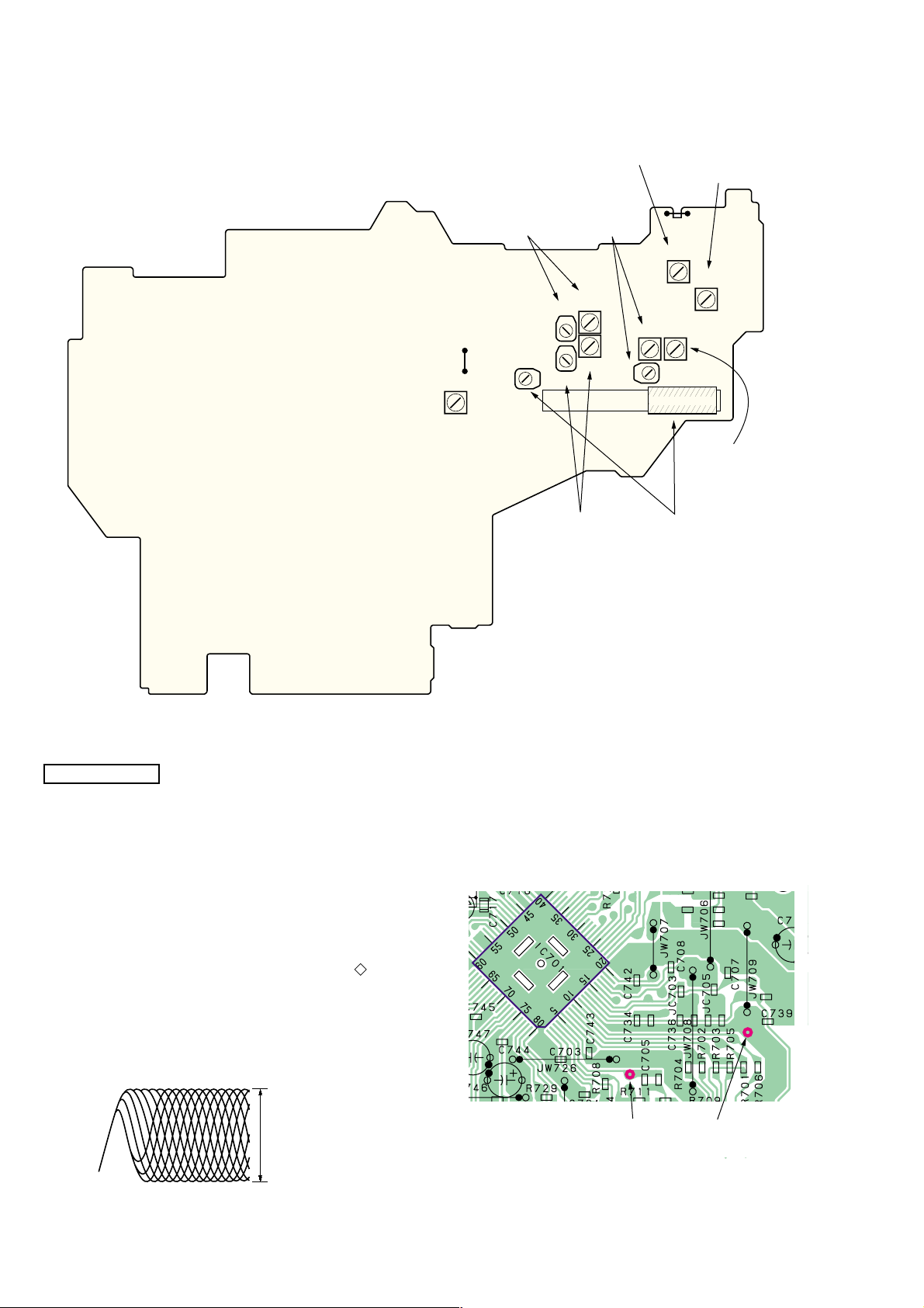
Adjustment Location:
– MAIN board (component side) –
L6
AM
FREQUENCY
COVERAGE
ADJUSTMENT
CT4, L3
TV-H/WB
FREQUENCY
COVERAGE
ADJUSTMENT
JW18
CT5
L6
ADJUSTMENT
CT2, L1
TV-H/WB
TRACKING
ADJUSTMENT
L3
CT4
L4
CT3
CT3, L4
FM/TV-L
FREQUENCY
COVERAGE
ADJUSTMENT
CT2
T2
FM/TV
IF
TP(JW1)
L1
L5
CT5, L5
TRACKING
ADJUSTMENT
T1
AM
IF
ADJUSTMENT
T2
T1
L2
L2
FM/TV-L
TRACKING
ADJUSTMEN
AM
CD SECTION
CD section adjustments are done automatically in this set.
In case of operation check, confirm that focus bias.
FOCUS BIAS CHECK
1. Connect the oscilloscope between IC701 pin 4 and pin qa (or
TP (RF) and TP (VREF).
2. Insert the disc (YEDS-18). (Part No. : 3-702-101-01)
3. Press the CD N X button.
4. Confirm that the oscilloscope waveform is as shown in the
figure below. (eye pattern)
A good eye pattern means that the diamond shape ( ) in the
center of the waveform can be clearly distinguished.
• RF signal reference waveform (eye pattern)
VOLT/DIV : 50 mV (10 : 1 probe in use)
TIME/DIV : 500 nS
RF level :
0.85 ± 0.2 Vp-p
When observing the eye pattern, set the oscilloscope for AC range
and raise vertical sensitivity.
Test Point:
14
SECTION 6
CONTROL (1) board
CONTROL (2) board
CONTROL (3) board
CD board
BATTERY TERMINAL (2) board
BATTERY TERMINAL (1) board
MAIN board
PRE board
POWER (1) board
POWER (2) board
DIAGRAMS
CFD-S36
6-1. IC PIN DESCRIPTION
• IC802 uPD789477-907 (SYSTEM CONTROLLER)
Pin No. Pin Name I/O Pin Description
10 – 26 S0 – 16 O LCD drive segment output
27 – 29 S17 – 19 O LCD drive segment output (Not used)
42 – 45 KEY1 – 4 I Key input
1, 2 NC — Not used (open)
3 – 5 VLC2 – 0 O LCD drive voltage output
6 – 9 COM0 – 3 O LCD drive common output
30 BL-CONT — Not used (open)
31 A-MUTE O Audio mute output H: Mute
32 WB/FM.AM.TV O Tuner output level attenuator switch
33 DBB O MEGA BASS control output H: MEGA BASS off, L: MEGA BASS on
34 P-CON O System power control output H: PCON
35 AC-CHK I AC power supply detection signal input “L”: AC in
36 CD O CD function output H: CD
37 TAPE O Tape function output H: Tape
38 AVDD — Analog power supply pin for A/D converter (+3.3 V)
39 BTT-CHK-H I Battery check input for Hi-voltage
40 BTT-CHK-M I Battery check input for Mid-voltage
41 REC I Tape record signal input H: REC
46 MODE CHK I Mode set input
47 AGND — Analog GND for A/D converter
48 REMOTE I Sircs receiver data input
49 TC-PLAY I Tape play switch input L: Tape
50 WP/INI O Initial set signal output
51 CD-DOOR I CD door open/close switch input L: Close
52 C-WRQ I CD command data input
53 C-DOUT I CD sireal data input
54 C-DIN O CD sireal data output
55 C-CLK I Serial data transfer clock signal input
56 R-COUNT I Tuner PLL data input
57 R-DATA O Tuner PLL data output
58 R-CLK O Tuner PLL clock output
59 R-LAT O Tuner PLL latch output
60 B-MUTE O Tuner mute signal output H: Mute
61 C-DRF I CD DRF signal input
62 C-CE O CD SENSE read clock output
63 C-FSEQ I CD frame SYNC input
64 C-XRT O CD system reset output
65 V-LAT O Volume latch output Not used. (Open)
66 V-DATA O Volume data output
67 V-CLK O Volume clock output
68 SUR O Surround switch signal output
69 ICO — Connected to GND
70 XT1 I Sub system oscillation input (32.768 kHz)
71 XT2 O Sub system oscillation output (32.768 kHz)
72 VDD — Main power supply pin for A/D converter (+3.3 V)
73 VSS — Main GND
74 X1 I Main system oscillation input (4.19 MHz)
Pin No. Pin Name I/O Pin Description
75 X2 O Main system oscillation output (4.19 MHz)
76 RST I System reset input
77 ISS1 O ISS1 output Not used. (Open)
78 ISS2 O ISS2 output Not used. (Open)
79 SCL O EEPROM clock output
80 SDA I/O EEPROM input/output
6-2. CIRCUIT BOARDS LOCATION
15 15
 Loading...