

Sony CDXS-22-S, CDXS-22 Service manual
CDX-S22/S22S
SERVICE MANUAL
Ver. 1.0 2005. 11
Photo: CDX-S22S
• The tuner and CD sections have no adjustments.
SPECIFICATIONS
CD player section
Signal-to-noise ratio 120 dB
Frequency response 10 – 20,000 Hz
Wow and flutter Below measurable limit
Tuner section
FM
Tuning range 87.5 – 108.0 MHz (AEP, UK, EA model)
87.5 – 108.0 MHz (at 50 kHz step)
(E, MX, CH model)
87.5 – 107.9 MHz (at 200 kHz step)
(E, MX, CH model)
FM tuning interval 50 kHz/200 kHz switchable (E, MX, CH model)
Aerial terminal External aerial connector
Intermediate frequency 10.7 MHz/450 kHz
Usable sensitivity 9 dBf
Selectivity 75 dB at 400 kHz
Signal-to-noise ratio 67 dB (stereo), 69 dB (mono)
Harmonic distortion at 1 kHz
0.5% (stereo), 0.3% (mono)
Separation 35 dB at 1 kHz
Frequency response 30 – 15,000 Hz
AEP Model
UK Model
CDX-S22
E Model
CDX-S22/S22S
Chinese Model
CDX-S22S
Model Name Using Similar Mechanism CDX-GT300/GT350S
CD Drive Mechanism Type MG-611WA-186//Q
Optical Pick-up Name KSS1000E
MW/LW (AEP, UK model)
Tuning range MW: 531 – 1,602 kHz
LW: 153 – 279 kHz
Aerial terminal External aerial connector
Intermediate frequency 10.7 MHz/450 kHz
Sensitivity MW: 30 µV, LW: 40 µV
AM (E, MX, CH, EA model)
Tuning range 531 – 1,602 kHz (EA model)
531 – 1,602 kHz (at 9 kHz step)
(E, MX, CH model)
530 – 1,710 kHz (at 10 kHz step)
(E, MX, CH model)
AM tuning interval 9 kHz/10 kHz switchable (E, MX, CH model)
Aerial terminal External aerial connector
Intermediate frequency 10.7 MHz/450 kHz
Sensitivity 30 µV
– Continued on next page –
9-879-956-01
2005K04-1
© 2005. 11
FM/AM COMPACT DISC PLAYER
CDX-S22: E, MX/S22S
FM/MW/LW COMPACT DISC PLAYER
CDX-S22: AEP, UK
Sony Corporation
eVehicle Division
Published by Sony Engineering Corporation
CDX-S22/S22S
Power amplifier section
Outputs Speaker outputs (sure seal connectors)
Speaker impedance 4 – 8 ohms
Maximum power output
52 W × 4 (at 4 ohms) (S22)
45 W × 4 (at 4 ohms) (S22S)
General
Outputs Audio outputs terminal
(sub/rear switchable)
Power aerial relay control terminal
Power amplifier control terminal
Inputs Telephone ATT control terminal
(AEP, UK model)
Aerial input terminal
Tone controls Low: ±10 dB at 60 Hz (XPLOD)
Mid: ±10 dB at 1 kHz (XPLOD)
High: ±10 dB at 10 kHz (XPLOD)
Power requirements 12 V DC car battery (negative earth)
Dimensions Approx. 178 × 50 × 178 mm
Mounting dimensions Approx. 182 × 53 × 161 mm
Mass Approx. 1.2 kg
Supplied accessories Parts for installation and connections (1 set)
US and foreign patents licensed from Dolby Laboratories.
MPEG Layer-3 audio coding technology and
patents licensed from Fraunhofer IIS and Thomson.
Design and specifications are subject to change without
notice.
Notes on Chip Component Replacement
• Never reuse a disconnected chip component.
• Notice that the minus side of a tantalum capacitor may be damaged
by heat.
TEST DISCS
This set can playback CD-R and CD-ROM discs. The following
test discs should be used to check the capability:
CD-R test disc TCD-R082LMT (Part No. J-2502-063-1)
CD-RW test disc TCD-W082L (Part No. J-2502-063-2)
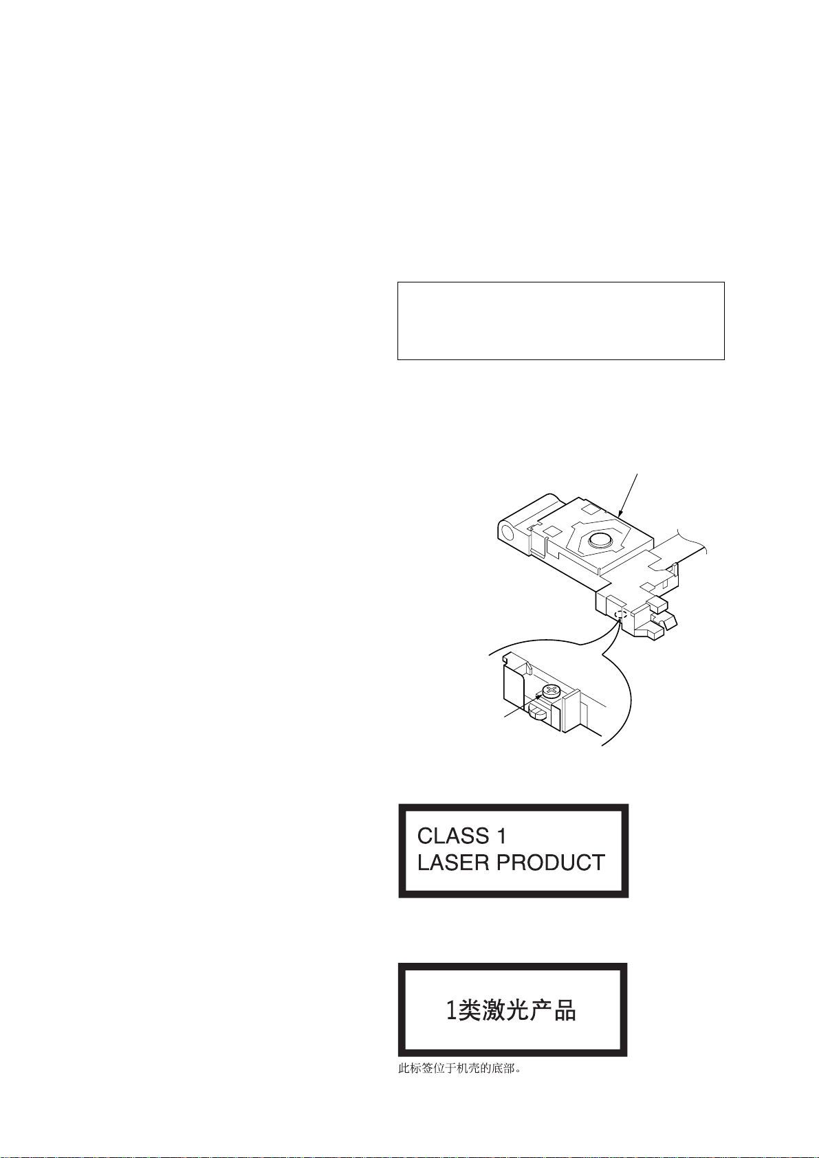
CAUTION
Use of controls or adjustments or performance of procedures
other than those specified herein may result in hazardous
radiation exposure.
If the optical pick-up block is defective, please replace the whole
optical pick-up block.
Never turn the semi-fix ed resistor located at the side of optical pickup block.
optical pick-up
• Abbreviation
EA : Saudi Arabia model
MX : Mexican model
CH : Chinese model
SERVICE NOTES
NOTES ON HANDLING THE OPTICAL PICK-UP BLOCK
OR BASE UNIT
The laser diode in the optical pick-up block may suffer electrostatic
breakdown because of the potential difference generated by the
charged electrostatic load, etc. on clothing and the human body.
During repair, pay attention to electrostatic breakdown and also use
the procedure in the printed matter which is included in the repair
parts.
The flexible board is easily damaged and should be handled with
care.
NOTES ON LASER DIODE EMISSION CHECK
The laser beam on this model is concentrated so as to be focused on
the disc reflective surface by the objective lens in the optical pickup block. Therefore, when checking the laser diode emission,
observe from more than 30 cm away from the objective lens.
semi-fixed resistor
EXCEPT CH model
This label is located on the bottom of the chassis.
SAFETY-RELATED COMPONENT WARNING!!
COMPONENTS IDENTIFIED BY MARK 0 OR DOTTED LINE
WITH MARK 0 ON THE SCHEMATIC DIAGRAMS AND IN
THE PARTS LIST ARE CRITICAL TO SAFE OPERATION.
REPLACE THESE COMPONENTS WITH SONY PARTS
WHOSE PART NUMBERS APPEAR AS SHOWN IN THIS
MANUAL OR IN SUPPLEMENTS PUBLISHED BY SONY.
2
CH model
CDX-S22/S22S
D
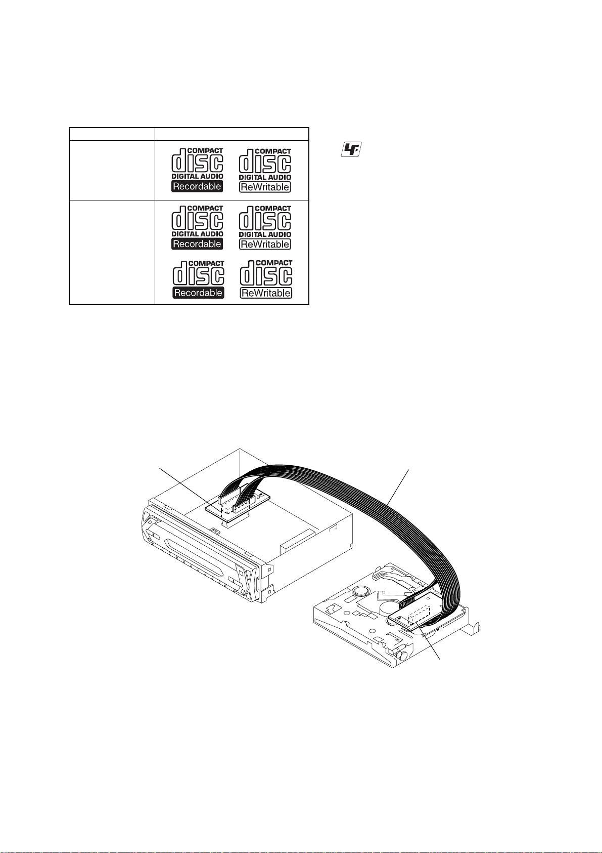
• CD Playback:
You can play CD-DA (also containing CD TEXT*
RW (MP3 files also containing Multi Session and ATRAC CD
(ATRAC3 and ATRAC3plus format).
Type of discs Label on the disc
CD-DA
MP3
ATRAC CD
*1 A CD TEXT disc is a CD-D A that includes information such as
disc, artist and track name.
EXTENSION CABLE AND SERVICE POSITION
When repairing or servicing this set, connect the jig (extension cable)
as shown below.
1
), CD-R/CD-
UNLEADED SOLDER
•
Boards requiring use of unleaded solder are printed with the leadfree mark (LF) indicating the solder contains no lead.
(Caution:Some printed circuit boards may not come printed with
the lead free mark due to their particular size.)
: LEAD FREE MARK
Unleaded solder has the following characteristics.
• Unleaded solder melts at a temperature about 40°C higher than
ordinary solder.
Ordinary soldering irons can be used but the iron tip has to be
applied to the solder joint for a slightly longer time.
Soldering irons using a temperature regulator should be set to
about 350°C.
Caution:The printed pattern (copper foil) may peel away if the
heated tip is applied for too long, so be careful!
• Strong viscosity
Unleaded solder is more viscous (sticky, less prone to flow)
than ordinary solder so use caution not to let solder bridges
occur such as on IC pins, etc.
• Usable with ordinary solder
It is best to use only unleaded solder but unleaded solder may
also be added to ordinary solder.
• Connect the MAIN board (CNP301) and the SER VO board (CN2)
with the extension cable (Part No. J-2502-076-1).
MAIN BOARD
CNP301
J-2502-076-1
SERVO BOAR
CN2
3

CDX-S22/S22S
T ABLE OF CONTENTS
1. GENERAL
Location of controls and basic operations
(AEP, UK model) ............................................................ 5
Connections (AEP, UK model) ....................................... 5
Location of controls and basic operations
(E, MX, CH, EA model).................................................. 7
Connections (E, MX, CH, EA model)............................. 7
2. DISASSEMBLY
2-1. Sub Panel (HEX) Assy .................................................... 10
2-2. CD Mechanism Block ..................................................... 10
2-3. Main Board ...................................................................... 11
2-4. Chassis (T) Sub Assy....................................................... 11
2-5. Roller Arm Assy .............................................................. 12
2-6. Chassis (OP) Assy ........................................................... 12
2-7. Optical Pick-up ................................................................ 13
2-8. SL Motor Assy (M902) ................................................... 13
2-9. LE Motor Assy (M903) ................................................... 14
2-10. Servo Board ..................................................................... 14
3. DIAGRAMS
3-1. Block Diagram –CD Section– ......................................... 15
3-2. Block Diagram –Main Section– ...................................... 16
3-3. Block Diagram –Key Section– ........................................ 17
3-4. Circuit Boards Location .................................................. 17
3-5. Printed Wiring Boards –CD Mechanism Section–.......... 19
3-6. Schematic Diagram –CD Mechanism Section (1/2)– ..... 20
3-7. Schematic Diagram –CD Mechanism Section (2/2)– ..... 21
3-8. Printed Wiring Board –Main Section– ............................ 22
3-9. Schematic Diagram –Main Section (1/3)– ...................... 23
3-10. Schematic Diagram –Main Section (2/3)– ...................... 24
3-11. Schematic Diagram –Main Section (3/3)– ...................... 25
3-12. Printed Wiring Board
–Key Section (AEP, UK model)– .................................... 26
3-13. Schematic Diagram
–Key Section (AEP, UK model)– .................................... 27
3-14. Printed Wiring Board
–Key Section (Except AEP, UK model)– ........................ 28
3-15. Schematic Diagram
–Key Section (Except AEP, UK model)– ........................ 29
4. EXPLODED VIEWS
4-1. Main Section.................................................................... 36
4-2. Front Panel Section ......................................................... 37
4-3. CD Mechanism Section (1) ............................................. 38
4-4. CD Mechanism Section (2) ............................................. 39
4-5. CD Mechanism Section (3) ............................................. 40
4-6. CD Mechanism Section (4) ............................................. 41
5. ELECTRICAL PARTS LIST .................................. 42
4
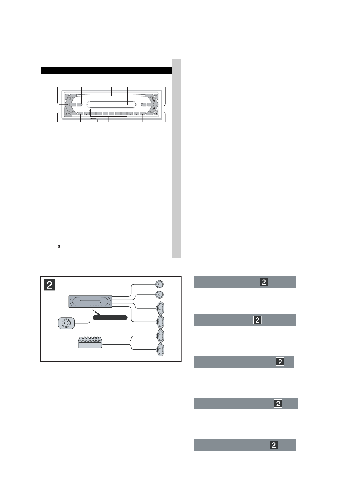
Location of controls and basic operations
(AEP, UK model)
Location of controls and basic operations
Main unit
1234 5 6 7890
SEL
SOURCE MODE
BTMDIM SHUF PAUSEREP
GROUP
–
SENS
DSPL
123456
qs qd qf qg qh qj qk
Refer to the pages listed for details.
A Volume +/– button
To adjust volume.
B SEL (select) button 4, 9
To select items.
C SOURCE button
To power on; change the source (Radio/CD).
D MODE button 6
To select the radio band (FM/MW/LW).
E Disc slot
Insert the disc (label side up), playback
starts.
F Display window
G ATT (attenuate) button
To attenuate the sound. To cancel, press
again.
H EQ3 (equalizer) button 9
To select an equalizer type (XPLOD ,
VOCAL, CLUB, JAZZ, NEW AGE, ROCK,
CUSTOM or OFF).
I Z (eject) button
To eject the disc.
J SEEK +/– button
CD:
To skip tracks (press); skip tracks
continuously (press, t h en press again within
about 1 second and hold); fast-fo rw ard/
reverse a track (press and hold).
Radio:
To tune in stati ons automatic ally (pre ss); fi nd
a station manually (press and hold).
K (front panel release) button 4
+
PTY OFF
L DSPL (display)/DIM (dimmer) button
4, 6, 7
To change display items (press); change the
display brightness (press and hold).
M SENS/BTM button 6
To improve weak rece ption: LOCAL/MONO
(press); start the BTM function (press and
hold).
N RESET button (located behind the front
panel) 4
O Number buttons
CD:
(1)/(2): GROUP* –/+
To skip groups (press); skip group s
continuously (press and hold ).
(3): REP 6
(4): SHUF 6
(6): PAUS E
To pause playback. To cancel, press
again.
Radio:
To receive stored stations (press); stor e
stations (press and hold).
P PTY (Programme Type) button 8
To s e le ct PT Y in R DS.
Q AF (Alternative Frequencies)/TA
(Traffic Announcement) button 7
To s e t A F a nd TA/TP in RDS.
R OFF button
To power off; stop the source.
S Receptor for the card remote
commander 10
*
When an MP3/ATRAC CD is played.
EQ3ATT
AF/TA
SECTION 1
GENERAL
SEEK
CDX-S22
qlqa
5
CDX-S22/S22S
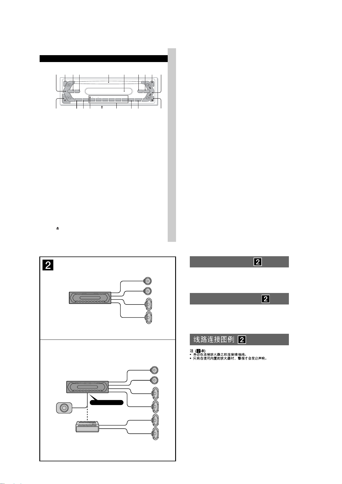
Connections (AEP, UK model)
AUDIO OUT REAR*
*
AUDIO OUT SUB/REAR
Connection example
Notes
•
Be sure to connect the earth lead before connecting the
amplifi er.
•
The alarm will only sound if the built-in amplifi er is used.
Anschlussbeispiel
Hinweise
•
Schließen Sie unbedingt zuerst das Massekabel an, bevor Sie
den Verstärker anschließen.
•
Der Alarm ist nur zu hören, wenn der integrierte Verstärker
verwendet wird.
Exemple de raccordement
Remarques
•
Raccordez d’abord le câble de mise à la masse avant de
connecter l’amplifi cateur.
•
L’alarme est émise uniquement lorsque l’amplifi cateur intégré
est utilisé.
Esempio di collegamento
Note
•
Assicurarsi di collegare il cavo di terra prima di collegare
l’apparecchio all’amplifi catore.
•
Il segnale viene emesso solo se si utilizza l’amplifi catore
incorporato.
Voorbeeldaansluitingen
Opmerkingen
•
Sluit eerst de aarddraad aan voordat u de versterker aansluit.
•
U hoort de waarschuwingstoon alleen als de ingebouwde
versterker wordt gebruikt.
5
CDX-S22/S22S
1
from car aerial
*
von Autoantenne
de l’antenne de la voiture
dall’antenna dell’auto
van een auto-antenne
Max. supply current 0.3 A
max. Versorgungsstrom 0,3 A
Courant d’alimentation maximum 0,3 A
Alimentazione massima fornita 0,3 A
Max. voedingsstroom 0,3 A
See “Power connection diagram” on the reverse side for details.
Näheres dazu fi nden Sie im „Stromanschlussdiagramm“. Blättern
Sie dazu bitte um.
Voir le « Schéma de raccordement d’alimentation » au verso pour
plus de détails.
Per ulteriori informazioni, vedere “Diagramma dei collegamenti di
alimentazione” che si trova sul retro.
Zie "Voedingsaansluitschema" op de achterkant voor meer details.
Connection diagram
A To AMP REMOTE IN of an optional power
amplifi er
This connection is only for amplifi ers. Connecting any other
system may damage the unit.
B To the interface cable of a car telephone
Warning
If you have a power aerial without a relay box,
connecting this unit with the supplied power connecting
lead 3 may damage the aerial.
Notes on the control power and suppy leads
•
The power aerial control lead (blue) supplies +12 V DC when
you turn on the tuner, or when you activate the AF (Alternative
Frequency) or TA (Traffi c Announcement) function.
•
When your car has built-in FM/MW/LW aerial in the rear/side
glass, connect the power aerial control lead (blue) or the
accessory power input lead (red) to the power terminal of the
existing aerial booster. For details, consult your dealer.
•
A power aerial without a relay box cannot be used with this
unit.
Memory hold connection
When the yellow power input lead is connected, power will
always be supplied to the memory circuit even when the ignition
switch is turned off.
Notes on speaker connection
•
Before connecting the speakers, turn the unit off.
•
Use speakers with an impedance of 4 to 8 ohms, and with
adequate power handling capacities to avoid its damage.
•
Do not connect the speaker terminals to the car chassis, or
connect the terminals of the right speakers with those of the
left speaker.
•
Do not connect the earth lead of this unit to the negative (–)
terminal of the speaker.
•
Do not attempt to connect the speakers in parallel.
•
Connect only passive speakers. Connecting active speakers
(with built-in amplifi ers) to the speaker terminals may damage
the unit.
•
To avoid a malfunction, do not use the built-in speaker leads
installed in your car if the unit shares a common negative (–)
lead for the right and left speakers.
•
Do not connect the unit’s speaker leads to each other.
Note on connection
If speaker and amplifi er are not connected correctly, “FAILURE”
appears in the display. In this case, make sure the speaker and
amplifi er are connected correctly.
2
*
AUDIO OUT REAR
AUDIO
OUT
2
AMP REM
ATT
Fuse (10 A)
Sicherung (10 A)
Fusible (10 A)
Fusibile (10 A)
Zekering (10 A)
Blue/white striped
Blauweiß gestreift
Rayé bleu/blanc
Rigato blu e bianco
Blauw/wit gestreept
Light blue
Hellblau
Bleu ciel
Azzurro
Lichtblauw
Anschlussdiagramm
A An AMP REMOTE IN des gesondert
erhältlichen Endverstärkers
Dieser Anschluss ist ausschließlich für Verstärker gedacht.
Schließen Sie nichts anderes daran an. Andernfalls kann
das Gerät beschädigt werden.
B An Schnittstellenkabel eines Autotelefons
Warnung
Wenn Sie eine Motorantenne ohne Relaiskästchen
verwenden, kann durch Anschließen dieses Geräts mit
dem mitgelieferten Stromversorgungskabel 3 die
Antenne beschädigt werden.
Steuer- und Stromversorgungsleitungen
•
Die Motorantennen-Steuerleitung (blau) liefert +12 V
Gleichstrom, wenn Sie den Tuner einschalten oder die
AF- (Alternativfrequenzsuche) oder die TA-Funktion
(Verkehrsdurchsagen) aktivieren.
•
Wenn das Fahrzeug mit einer in der Heck-/
Seitenfensterscheibe integrierten FM (UKW)/MW/LWAntenne ausgestattet ist, schließen Sie die MotorantennenSteuerleitung (blau) oder die Zubehörstromversorgungsleitung
(rot) an den Stromversorgungsanschluss des vorhandenen
Antennenverstärkers an. Näheres dazu erfahren Sie bei Ihrem
Händler.
•
Es kann nur eine Motorantenne mit Relaiskästchen
angeschlossen werden.
Stromversorgung des Speichers
Wenn die gelbe Stromversorgungsleitung angeschlossen ist,
wird der Speicher stets (auch bei ausgeschalteter Zündung) mit
Strom versorgt.
Hinweise zum Lautsprecheranschluss
•
Schalten Sie das Gerät aus, bevor Sie die Lautsprecher
anschließen.
•
Verwenden Sie Lautsprecher mit einer Impedanz zwischen 4 und
8 Ohm und ausreichender Belastbarkeit. Ansonsten können die
Lautsprecher beschädigt werden.
•
Verbinden Sie die Lautsprecheranschlüsse nicht mit dem
Wagenchassis und verbinden Sie auch nicht die Anschlüsse
des rechten mit denen des linken Lautsprechers.
•
Verbinden Sie die Masseleitung dieses Geräts nicht mit dem
negativen (–) Lautsprecheranschluss.
•
Versuchen Sie nicht, Lautsprecher parallel anzuschließen.
•
An die Lautsprecheranschlüsse dieses Geräts dürfen nur
Passivlautsprecher angeschlossen werden. Schließen Sie
keine Aktivlautsprecher (Lautsprecher mit eingebauten
Verstärkern) an, da das Gerät sonst beschädigt werden
könnte.
•
Um Fehlfunktionen zu vermeiden, verwenden Sie nicht die
im Fahrzeug installierten, integrierten Lautsprecherleitungen,
wenn am Ende eine gemeinsame negative (–) Leitung für den
rechten und den linken Lautsprecher verwendet wird.
•
Verbinden Sie nicht die Lautsprecherkabel des Geräts
miteinander.
Hinweis zum Anschlieflen
Wenn Lautsprecher und Verstärker nicht richtig angeschlossen
sind, erscheint „FAILURE“ im Display. Vergewissern Sie sich
in diesem Fall, dass Lautsprecher und Verstärker richtig
angeschlossen sind.
1
*
Note for the aerial connecting
If your car aerial is an ISO (International
Organisation for Standardisation) type,
use the supplied adaptor
it. First connect the car aerial to the
supplied adaptor, then connect it to the
aerial jack of the master unit.
2
*
RCA pin cord (not supplied)
3
*
AUDIO OUT can be switched REAR
or SUB. For details, see the Operating
3
*
Instructions manual.
3
4
5
Positions 1, 2, 3 and 6 do not have pins.
An Position 1, 2, 3 und 6 befi nden sich keine Stifte.
Les positions 1, 2, 3 et 6 ne comportent pas de broches.
Le posizioni 1, 2, 3 e 6 non hanno piedini.
De posities 1, 2, 3 en 6 hebben geen pins.
1
*
Hinweis zum Anschließen der Antenne
Wenn Ihre Fahrzeugantenne der
ISO-Norm (ISO = International
Organization for Standardization -
2
to connect
Internationale Normungsgemeinschaft)
entspricht, schließen Sie sie
mithilfe des mitgelieferten Adapters
2
an. Verbinden Sie zuerst die
Fahrzeugantenne mit dem mitgelieferten
Adapter und verbinden Sie diesen
dann mit der Antennenbuchse des
Hauptgeräts.
2
*
Cinchkabel (nicht mitgeliefert)
3
*
AUDIO OUT kann zwischen REAR
und SUB umgeschaltet werden.
Näheres hierzu fi nden Sie in der
Bedienungsanleitung.
from the car’s power connector
vom Stromanschluss des Fahrzeugs
du connecteur d’alimentation de la voiture
dal connettore di alimentazione dell’auto
van de autovoedingsstekker
Yellow
continuous power supply
Gelb
permanente Stromversorgung
Jaune
Giallo
Geel
Blue
Blau
Motorantennensteuerung
Bleu
Blu
comando dell’antenna elettrica
Blauw
alimentation continue
alimentazione continua
continu voeding
power aerial control
antenne électrique
automatische antenne
Red
Rot
7
Rouge
Rosso
Rood
Black
Schwarz
8
Noir
Nero
Zwart
Schémas de raccordement
A Au niveau du AMP REMOTE IN d’un
amplifi cateur de puissance facultatif
Ce raccordement existe seulement pour les amplifi cateurs.
Le raccordement à tout autre système peut endommager
l’appareil.
B Vers le cordon de liaison d’un téléphone de
voiture
Avertissement
Si vous disposez d’une antenne électrique sans boîtier
de relais, le branchement de cet appareil au moyen du
cordon d’alimentation fourni 3 risque d’endommager
l’antenne.
Remarques sur les câbles de commande et de puissance
•
Le câble de commande (bleu) fournit du courant continu de
+12 V lorsque vous mettez le tuner sous tension ou lorsque
vous activez la fonction AF (fréquence alternative) ou TA
(informations circulation).
•
Lorsque votre voiture est équipée d’une antenne FM/MW
(GO)/LW (PO) intégrée dans la vitre arrière/latérale,
raccordez le câble de commande d’antenne (bleu) ou
l’entrée d’alimentation des accessoires (rouge) au bornier
de l’amplifi cateur d’antenne existant. Pour plus de détails,
consultez votre revendeur.
•
Une antenne électrique sans boîtier de relais ne peut pas être
utilisée avec cet appareil.
Raccordement pour la conservation de la mémoire
Lorsque le câble de commande d’antenne jaune est connecté,
le circuit de la mémoire est alimenté en permanence même si la
clé de contact est en position d’arrêt.
Remarques sur le raccordement des haut-parleurs
•
Avant de raccorder les haut-parleurs, mettre l’appareil hors
tension.
•
Utiliser des haut-parleurs ayant une impédance de 4
à 8 ohms et une capacité adéquate sous peine de les
endommager.
•
Ne pas raccorder les bornes du système de haut-parleurs au
châssis de la voiture et ne pas connecter les bornes du hautparleur droit à celles du haut-parleur gauche.
•
Ne pas raccorder le câble de mise à la masse de cet appareil
à la borne négative (–) du haut-parleur.
•
Ne pas tenter de raccorder les haut-parleurs en parallèle.
•
Connectez uniquement des haut-parleurs passifs. La
connexion de haut-parleurs actifs (avec des amplifi cateurs
intégrés) aux bornes des haut-parleurs pourrait endommager
l’appareil.
•
Pour éviter tout dysfonctionnement, n’utilisez pas les câbles
des haut-parleurs intégrés installés dans votre voiture si
l’appareil dispose d’un câble négatif commun (–) pour les
haut-parleurs droit et gauche.
•
Ne raccordez pas entre eux les cordons des haut-parleurs de
l’appareil.
Remarque sur le raccordement
Si les enceintes et l’amplifi cateur ne sont pas raccordés
correctement, le message « FAILURE » s’affi che. Dans ce cas,
assurez-vous que les enceintes et l’amplifi cateur sont raccordés
correctement.
1
*
Remarque sur le raccordement de
l’antenne
Si votre antenne de voiture est de type
ISO (Organisation internationale de
normalisation), utilisez l’adaptateur
fourni
2
pour la raccorder. Raccordez
d’abord l’antenne de voiture à
l’adaptateur fourni et, ensuite, à la prise
d’antenne de l’appareil principal.
2
*
Cordon à broche RCA (non fourni)
3
*
AUDIO OUT peut être commuté sur
REAR ou SUB. Pour obtenir plus
de détails, reportez-vous au mode
d’emploi.
57
1
Purple
Violett
Mauve
Viola
Paars
48
switched power supply
geschaltete Stromversorgung
alimentation commutée
alimentazione commutata
geschakelde voeding
earth
Masse
masse
terra
aarding
2–
3
Grey
Grau
Gris
Grigio
Grijs
4–
Negative polarity positions 2, 4, 6, and 8 have striped leads.
An den negativ gepolten Positionen 2, 4, 6 und 8 befi nden sich gestreifte Adern.
Les positions de polarité négative 2, 4, 6 et 8 sont dotées de cordons rayés.
Le posizioni a polarità negativa 2, 4, 6 e 8 hanno cavi rigati.
De posities voor negatieve polariteit (2, 4, 6 en 8) hebben gestreepte kabels.
Schema di collegamento
A A AMP REMOTE IN di un amplifi catore di
potenza opzionale
Questo collegamento è riservato esclusivamente agli
amplifi catori. Non collegare un tipo di sistema diverso onde
evitare di causare danni all’apparecchio.
B Al cavo interfaccia di un telefono per auto
Avvertenza
Quando si collega l’apparecchio con il cavo di
alimentazione in dotazione 3, si potrebbe danneggiare
l’antenna elettrica se questa non dispone di scatola a relè.
Note sui cavi di controllo e di alimentazione
•
Il cavo (blu) di controllo dell’antenna elettrica fornisce
alimentazione pari a +12 V CC quando si attiva il sintonizzatore
oppure la funzione TA (notiziario sul traffi co) o AF (frequenza
alternativa).
•
Se l’automobile è dotata di antenna FM/MW/LW incorporata
nel vetro posteriore/laterale, collegare il cavo (blu) di
controllo dell’antenna elettrica o il cavo (rosso) di ingresso
dell’alimentazione accessoria al terminale di alimentazione
del preamplifi catore dell’antenna esistente. Per ulteriori
informazioni, consultare il proprio fornitore.
•
Non è possibile usare un’antenna elettrica senza scatola a relè
con questo apparecchio.
Collegamento per la conservazione della memoria
Quando il cavo di ingresso alimentazione giallo è collegato, viene
sempre fornita alimentazione al circuito di memoria anche quando
l’interruttore di accensione è spento.
Note sul collegamento dei diffusori
•
Prima di collegare i diffusori spegnere l’apparecchio.
•
Usare diffusori di impedenza compresa tra 4 e 8 ohm e con
capacità di potenza adeguata, altrimenti i diffusori potrebbero
venir danneggiati.
•
Non collegare i terminali del sistema diffusori al telaio dell’auto
e non collegare i terminali del diffusore destro a quelli del
diffusore sinistro.
•
Non collegare il cavo di terra di questo apparecchio al terminale
negativo (–) del diffusore.
•
Non collegare i diffusori in parallelo.
•
Assicurarsi di collegare soltanto diffusori passivi, poiché il
collegamento di diffusori attivi, dotati di amplifi catori incorporati,
ai terminali dei diffusori potrebbe danneggiare l’apparecchio.
•
Per evitare problemi di funzionamento, non utilizzare i cavi dei
diffusori incorporati installati nell’automobile se l’apparecchio
condivide un cavo comune negativo (–) per i diffusori destro e
sinistro.
•
Non collegare fra loro i cavi dei diffusori dell’apparecchio.
Nota sui collegamenti
Se l’amplifi catore e il diffusore non sono collegati correttamente,
“FAILURE” viene visualizzato nel display. In tal caso, accertarsi
che l’amplifi catore e il diffusore siano collegati correttamente.
1
*
Nota per il collegamento dell’antenna
Se l’antenna dell’auto è di tipo
ISO (International Organization for
Standardization), utilizzare l’adattatore
2
in dotazione per collegarla. Collegare
prima l’antenna della macchina
all’adattatore in dotazione, quindi
collegarla alla presa dell’antenna
dell’apparecchio principale.
2
*
Cavo a piedini RCA (non in dotazione)
3
*
AUDIO OUT può essere impostato
su REAR o su SUB. Per ulteriori
informazioni, consultare il manuale di
istruzioni per l’uso.
from the car’s speaker connector
vom Lautsprecheranschluss des Fahrzeugs
du connecteur de haut-parleur de la voiture
dal connettore del diffusore dell’auto
van de autoluidsprekerstekker
Speaker, Rear, Right
Lautsprecher hinten rechts
+
Haut-parleur, arrière, droit
Diffusore, posteriore, destro
Luidspreker, achter, rechts
Speaker, Rear, Right
Lautsprecher hinten rechts
Haut-parleur, arrière, droit
Diffusore, posteriore, destro
Luidspreker, achter, rechts
Speaker, Front, Right
Lautsprecher vorne rechts
Haut-parleur, avant, droit
+
Diffusore, anteriore, destro
Luidspreker, voor, rechts
Speaker, Front, Right
Lautsprecher vorne rechts
Haut-parleur, avant, droit
Diffusore, anteriore, destro
Luidspreker, voor, rechts
1
*
Opmerking bij de antenne-aansluiting
Indien uw auto is uitgerust met een
antenne van het type ISO (International
Organisation for Standardization),
moet u die aansluiten met behulp
van de bijgeleverde adapter
eerst de auto-antenne aan op de
meegeleverde adapter en vervolgens de
antennestekker op het hoofdtoestel.
2
*
Tulpstekkersnoer (niet bijgeleverd)
3
*
AUDIO OUT kan worden ingesteld
op REAR of SUB. Raadpleeg de
handleiding met gebruiksaanwijzingen
voor meer informatie.
2
. Sluit
13 57
24 68
Speaker, Front, Left
White
Weiß
Blanc
Bianco
Green
Grün
Vert
Verde
Groen
Wit
Lautsprecher vorne links
+
Haut-parleur, avant, gauche
Diffusore, anteriore, sinistro
Luidspreker, voor, links
Speaker, Front, Left
Lautsprecher vorne links
Haut-parleur, avant, gauche
Diffusore, anteriore, sinistro
Luidspreker, voor, links
Speaker, Rear, Left
Lautsprecher hinten links
+
Haut-parleur, arrière, gauche
Diffusore, posteriore, sinistro
Luidspreker, achter, links
Speaker, Rear, Left
Lautsprecher hinten links
Haut-parleur, arrière, gauche
Diffusore, posteriore, sinistro
Luidspreker, achter, links
5
6–
7
8–
Aansluitschema
A Naar AMP REMOTE IN van een optionele
eindversterker
Deze aansluiting is alleen bedoeld voor versterkers. Door
een ander systeem aan te sluiten kan het apparaat worden
beschadigd.
B Naar het interface-snoer van een
autotelefoon
Waarschuwing
Indien u een elektrische antenne heeft zonder relaiskast,
kan het aansluiten van deze eenheid met het bijgeleverde
netsnoer 3 de antenne beschadigen.
Opmerkingen over de bedienings- en voedingskabels
•
De antennevoedingskabel (blauw) levert +12 V gelijkstroom
wanneer u de tuner inschakelt of de AF (Alternative
Frequency) of TA (Traffi c Announcement) functie activeert.
•
Wanneer uw auto is uitgerust met een FM/MW/LW-antenne
in de achterruit/voorruit, moet u de antennevoedingskabel
(blauw) of de hulpvoedingskabel (rood) aansluiten op de
voedingsingang van de bestaande antenneversterker.
Raadpleeg uw dealer voor meer details.
•
Met dit apparaat is het niet mogelijk een automatische antenne
zonder relaiskast te gebruiken.
Instandhouden van het geheugen
Zolang de gele stroomdraad is aangesloten, blijft de
stroomvoorziening van het geheugen intact, ook wanneer het
contact van de auto wordt uitgeschakeld.
Opmerkingen betreffende het aansluiten van de luidsprekers
•
Zorg dat het apparaat is uitgeschakeld, alvorens de
luidsprekers aan te sluiten.
•
Gebruik luidsprekers met een impedantie van 4 tot 8 Ohm
en let op dat die het vermogen van de versterker kunnen
verwerken. Als dit wordt verzuimd, kunnen de luidsprekers
ernstig beschadigd raken.
•
Verbind in geen geval de aansluitingen van de luidsprekers
met het chassis van de auto en sluit de aansluitingen van de
rechter- en linkerluidspreker niet op elkaar aan.
•
Verbind de aarddraad van dit apparaat niet met de negatieve
(–) aansluiting van de luidspreker.
•
Probeer nooit de luidsprekers parallel aan te sluiten.
•
Sluit geen actieve luidsprekers (met ingebouwde versterkers)
aan op de luidspreker-aansluiting van dit apparaat. Dit zal
leiden tot beschadiging van de actieve luidsprekers. Sluit dus
altijd uitsluitend luidsprekers zonder ingebouwde versterker
aan.
•
Om defecten te vermijden mag u de bestaande
luidsprekerbedrading in uw auto niet gebruiken wanneer er een
gemeenschappelijke negatieve (–) draad is voor de rechter- en
linkerluidsprekers.
•
Verbind de luidsprekerdraden niet met elkaar.
Opmerking over aansluiten
Als de luidspreker en versterker niet correct zijn aangesloten,
wordt "FAILURE" in het display weergegeven. In dit geval moet u
zorgen dat de luidspreker en versterker correct zijn aangesloten.
6
Location of controls and basic operations
q
qsq
q
q
qjq
q
(E, MX, CH, EA model)
Location of controls and basic operations
Main unit
1234 5 6 7890
SEL
SOURCE MODE
DIM
GROUP
–
SENS BTM OFFDSPL 1 2 3 4 5 6
a
Refer to the pages listed for details.
A Volume +/– button
To adjust volume.
B SEL (select) button 4, 7
To select items.
C SOURCE button
To power on; change the source (Radio/CD).
D MODE button 6
To select the radio band (FM/AM).
E Disc slot
Insert the disc (label side up), playback
starts.
F Display window
G ATT (attenuate) button
To attenuate the sound. To cancel, press
again.
H EQ3 (equalizer) button 7
To select an equalizer type (XPLOD,
VOCAL, CLUB, JAZZ, NEWAGE, ROCK,
CUSTOM or OFF).
I Z (eject) button
To eject the disc.
J SEEK +/– button
CD:
To skip tracks (press); skip tracks
continuously (press, t h en press again within
about 1 second and hold); fast-fo rw ard/
reverse a track (press and hold).
Radio:
To tune in stati ons automatic ally (pre ss); fi nd
a station manually (press and hold).
K (front panel release) button 4
d
f
SHUFREP
+
g
PAUSE
h
L DSPL (display)/DIM (dimmer) button
4, 6
To change display items (press); change the
display brightness (press and hold).
M SENS button
To improve weak reception: LOCAL/
MONO.
N RESET button (located behind the front
panel) 4
O Frequency select switch (located on the
bottom of the unit)
See “Frequency select sw i tch” in the
supplied installation/connections manual.
P Number buttons
CD:
(1)/(2): GROUP* –/+
To skip groups (press); skip groups
continuously (press and hold ).
(3): REP 6
(4): SHUF 6
(6): PAUS E
To pause playback. To cancel, press
again.
Radio:
To receive stored stations (press); stor e
stations (press and hold).
Q BTM button 6
To start the BTM function (press and hold).
R OFF button
To power off; stop the source.
S Receptor for the card remote
commander 8
*
When an MP3/ATRAC CD is played.
EQ3ATT
CDX-S22S
CDX-S22
k
CDX-S22/S22S
SEEK
ql
5
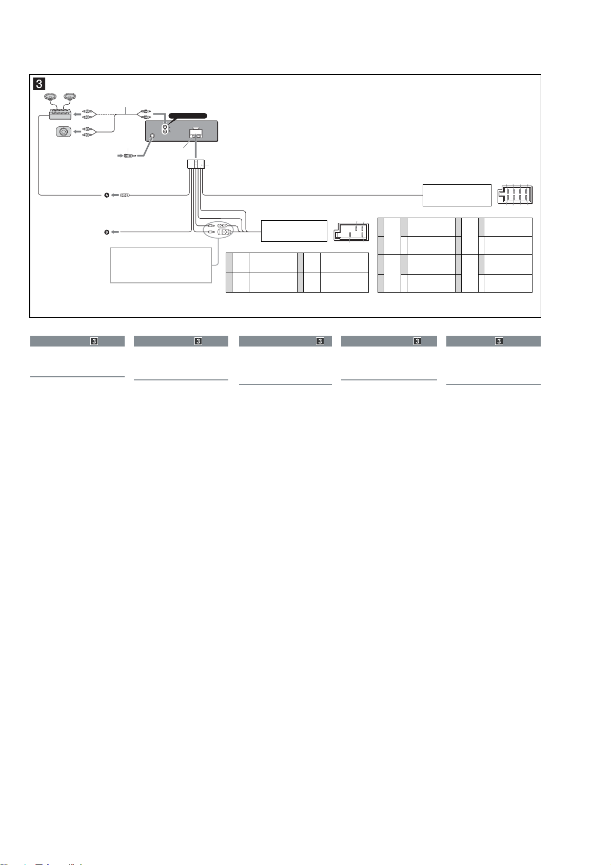
Connections (E, MX, CH, EA model)
A
B
AUDIO OUT REAR
*
Connection example
Notes
(2-B)
Be sure to connect the earth lead before connecting the
•
amplifi er.
•
The alarm will only sound if the built-in amplifi er is used.
Ejemplo de conexiones
Notas
(2-B)
Asegúrese de conectar primero el cable de conexión a masa
•
antes de realizar la conexión al amplifi cador.
•
Los pitidos se activarán únicamente si se utiliza el amplifi cador
integrado.
*
AUDIO OUT SUB/REAR
7
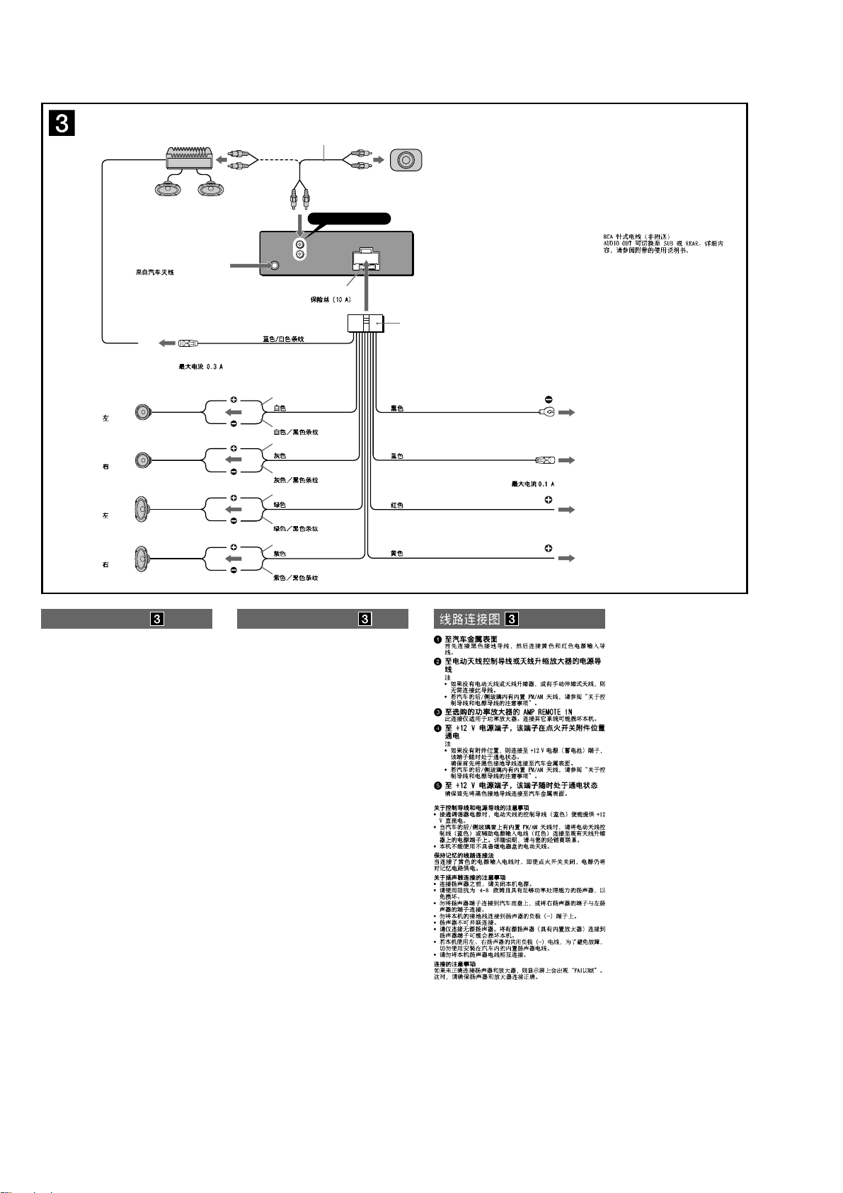
CDX-S22/S22S
from car aerial
desde la antena del automóvil
1
*
AUDIO OUT REAR
L
R
AUDIO
OUT
Fuse (10 A)
Fusible (10 A)
1
*
RCA pin cord (not supplied)
2
*
AUDIO OUT can be switched to SUB
or REAR.
For details, see the supplied
Operating Instructions.
1
*
Cable con terminales RCA
(no suministrado)
2
*
AUDIO OUT (Salida de audio) puede
cambiarse a SUB (Secundaria) o REAR
(Posterior). Para obtener información,
2
*
consulte el manual de instrucciones
suministrado.
1
*
2
*
AMP REM
3
Max. supply current 0.3 A
Corriente máx. de alimentación de 0,3 A
Left
Izquierdo
Right
Derecho
Left
Izquierdo
Right
Derecho
Connection diagram
1 To a metal surface of the car
First connect the black earth lead, then connect the yellow
and red power input leads.
2 To the power aerial control lead or power
supply lead of aerial booster amplifi er
Notes
•
It is not necessary to connect this lead if there is no power
aerial or aerial booster, or with a manually-operated
telescopic aerial.
•
When your car has a built-in FM/AM aerial in the rear/side
glass, see “Notes on the control and power supply leads.”
3 To AMP REMOTE IN of an optional power
amplifi er
This connection is only for amplifi ers. Connecting any other
system may damage the unit.
4 To the +12 V power terminal which is
energized in the accessory position of the
ignition key switch
Notes
•
If there is no accessory position, connect to the +12 V
power (battery) terminal which is energized at all times.
Be sure to connect the black earth lead to a metal surface
of the car fi rst.
•
When your car has a built-in FM/AM aerial in the rear/side
glass, see “Notes on the control and power supply leads.”
5 To the +12 V power terminal which is
energized at all times
Be sure to connect the black earth lead to a metal surface
of the car fi rst.
Notes on the control and power supply leads
•
The power aerial control lead (blue) supplies +12 V DC when
you turn on the tuner.
•
When your car has built-in FM/AM aerial in the rear/side glass,
connect the power aerial control lead (blue) or the accessory
power input lead (red) to the power terminal of the existing
aerial booster. For details, consult your dealer.
•
A power aerial without a relay box cannot be used with this
unit.
Memory hold connection
When the yellow power input lead is connected, power will
always be supplied to the memory circuit even when the ignition
switch is turned off.
Notes on speaker connection
•
Before connecting the speakers, turn the unit off.
•
Use speakers with an impedance of 4 to 8 ohms, and with
adequate power handling capacities to avoid its damage.
•
Do not connect the speaker terminals to the car chassis, or
connect the terminals of the right speakers with those of the
left speaker.
•
Do not connect the earth lead of this unit to the negative (–)
terminal of the speaker.
•
Do not attempt to connect the speakers in parallel.
•
Connect only passive speakers. Connecting active speakers
(with built-in amplifi ers) to the speaker terminals may damage
the unit.
•
To avoid a malfunction, do not use the built-in speaker leads
installed in your car if the unit shares a common negative (–)
lead for the right and left speakers.
•
Do not connect the unit’s speaker leads to each other.
Note on connection
If speaker and amplifi er are not connected correctly, “FAILURE”
appears in the display. In this case, make sure the speaker and
amplifi er are connected correctly.
Blue/white striped
Con rayas azules y blancas
White
Blanco
White/black striped
Con rayas blancas y negras
Grey
Gris
Grey/black striped
Con rayas grises y negras
Green
Verde
Green/black striped
Con rayas verdes y negras
Purple
Morado
Purple/black striped
Con rayas moradas y negras
Black
Negro
Blue
Azul
Red
Rojo
Yellow
Amarillo
Diagrama de conexión
1 A una superfi cie metálica del automóvil
Conecte primero el cable de conexión a masa negro,
y después los cables amarillo y rojo de entrada de
alimentación.
2 Al cable de control de la antena motorizada
o al cable de fuente de alimentación del
amplifi cador de señal de la antena
Notas
•
Si no se dispone de antena motorizada ni de amplifi cador
de antena, o se utiliza una antena telescópica accionada
manualmente, no será necesario conectar este cable.
•
Si el automóvil incorpora una antena de FM/AM en el
cristal trasero o lateral, consulte “Notas sobre los cables
de control y de fuente de alimentación”.
3 A AMP REMOTE IN de un amplifi cador de
potencia opcional
Esta conexión es sólo para amplifi cadores. La conexión de
cualquier otro sistema puede dañar la unidad.
4 Al terminal de alimentación de +12 V que
recibe energía en la posición de accesorio
del interruptor de la llave de encendido
Notas
•
Si no hay posición de accesorio, conéctelo al terminal de
alimentación (batería) de +12 V que recibe energía sin
interrupción.
Asegúrese de conectar primero el cable de conexión a
masa negro a una superfi cie metálica del automóvil.
•
Si el automóvil incorpora una antena de FM/AM en el
cristal trasero o lateral, consulte “Notas sobre los cables
de control y de fuente de alimentación”.
5 Al terminal de alimentación de +12 V que
recibe energía sin interrupción
Asegúrese de conectar primero el cable de conexión a masa
negro a una superfi cie metálica del automóvil.
Notas sobre los cables de control y de fuente de
alimentación
•
El cable de control de la antena motorizada (azul) suministrará
cc de +12V cuando conecte la alimentación del sintonizador.
•
Si el automóvil dispone de una antena de FM/AM incorporada
en el cristal trasero o lateral, conecte el cable de control de
antena motorizada (azul) o el cable de entrada de alimentación
auxiliar (rojo) al terminal de alimentación del amplifi cador de
antena existente. Para obtener más información, consulte a su
distribuidor.
•
Con esta unidad no es posible utilizar una antena motorizada
sin caja de relé.
Conexión para protección de la memoria
Si conecta el cable de entrada de alimentación amarillo, el
circuito de la memoria recibirá siempre alimentación, aunque
apague la llave de encendido.
Notas sobre la conexión de los altavoces
•
Antes de conectar los altavoces, desconecte la alimentación
de la unidad.
•
Utilice altavoces con una impedancia de 4 a 8 con la
capacidad de potencia adecuada para evitar que se dañen.
•
No conecte los terminales de altavoz al chasis del automóvil,
ni conecte los terminales del altavoz derecho con los del
izquierdo.
•
No conecte el cable de conexión a masa de esta unidad al
terminal negativo (–) del altavoz.
•
No intente conectar los altavoces en paralelo.
•
Conecte solamente altavoces pasivos. Si conecta altavoces
activos (con amplifi cadores incorporados) a los terminales de
altavoz, puede dañar la unidad.
•
Para evitar fallas de funcionamiento, no utilice los cables de
altavoz incorporados instalados en el automóvil si su unidad
comparte un cable negativo común (–) para los altavoces
derecho e izquierdo.
•
No conecte los cables de altavoz de la unidad entre sí.
Nota sobre la conexión
Si el altavoz y el amplifi cador no están conectados
correctamente, aparecerá “FAILURE” en la pantalla. Si es así,
compruebe la conexión de ambos dispositivos.
2
Corriente máx. de alimentación de 0,1 A
ANT REM
Max. supply current 0.1 A
1
2
4
5
8
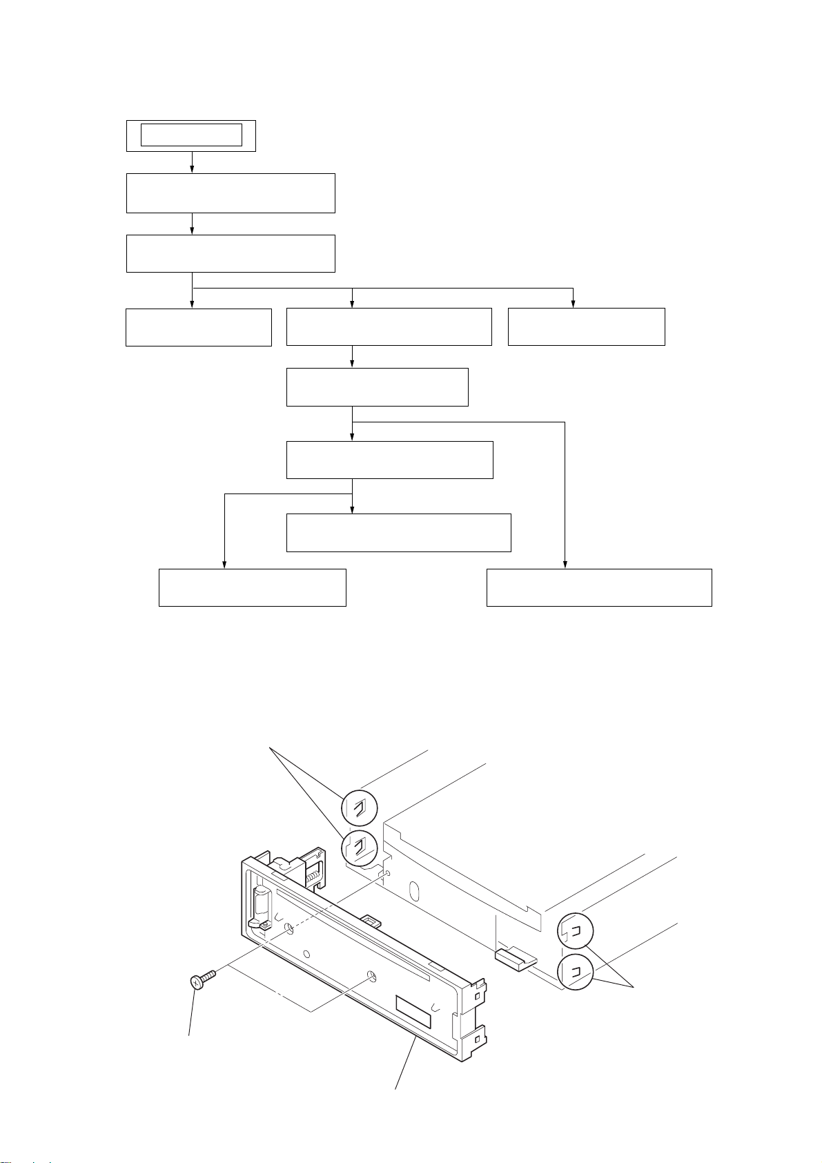
SECTION 2
DISASSEMBLY
Note: This set can be disassemble according to the following sequence.
SET
2-1. SUB PANEL (HEX) ASSY
(Page 9)
2-2. CD MECHANISM BLOCK
(Page 10)
CDX-S22/S22S
2-3. MAIN BOARD
(Page 10)
2-4. CHASSIS (T) SUB ASSY
(Page 11)
2-5. ROLLER ARM ASSY
(Page 11)
2-6. CHASSIS (OP) ASSY
(Page 12)
2-8. SL MOTOR ASSY (M902)
(Page 13)
2-7. OPTICAL PICK-UP
(Page 12)
Note: Follow the disassembly procedure in the numerical order given.
2-1. SUB PANEL (HEX) ASSY
2-10. SERVO BOARD
(Page 14)
2-9. LE MOTOR ASSY (M903)
(Page 13)
1
two
screws
(+PTT 2.6
×
3
two claws
6)
4
sub panel (HEX) assy
2
two claws
9
CDX-S22/S22S
)
)
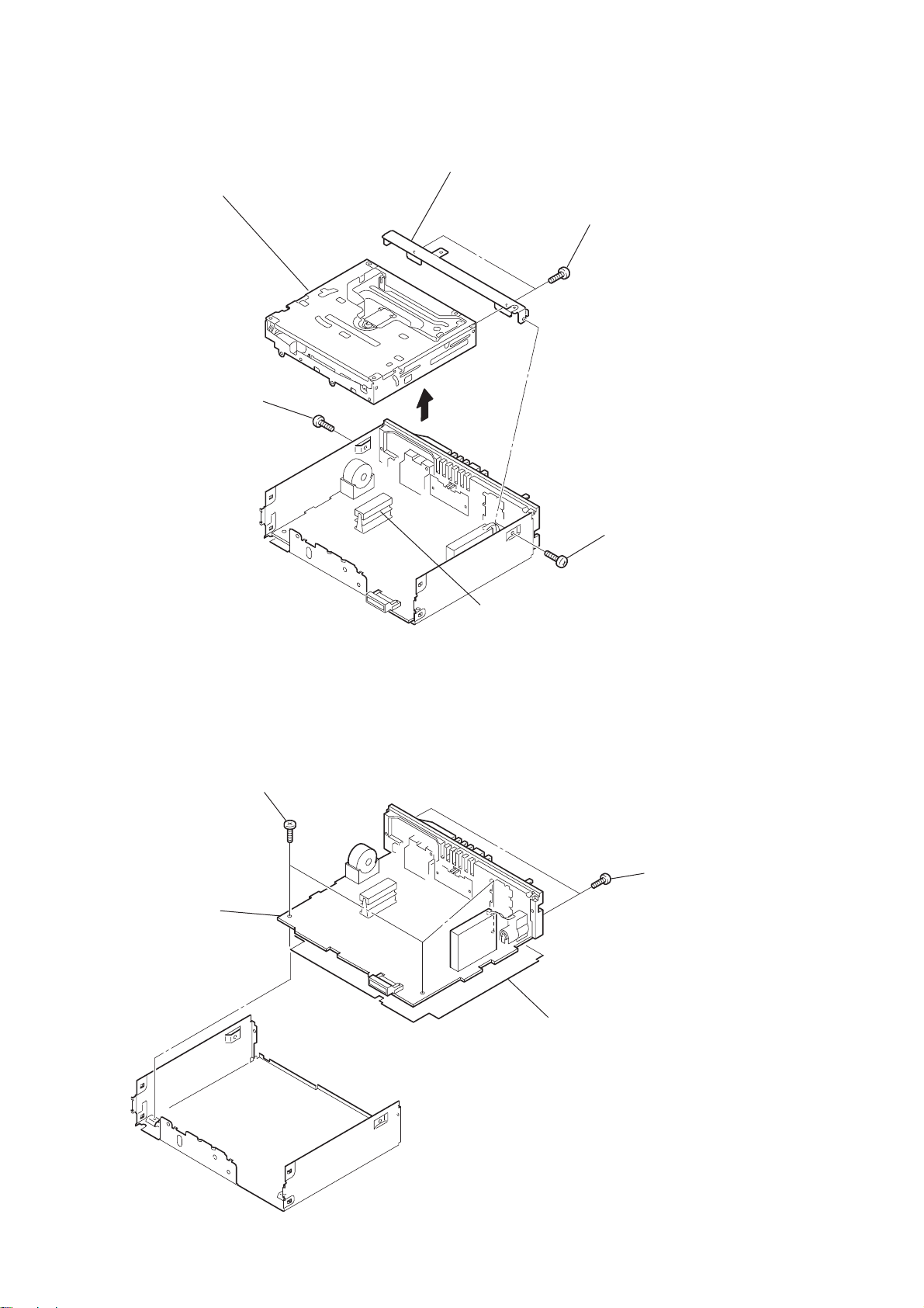
2-2. CD MECHANISM BLOCK
7
CD mechanism block
2
screw
(+PTT 2.6
×
6)
6
bracket (CD)
3
5
two
screws
(+PTT 2.6
×
4)
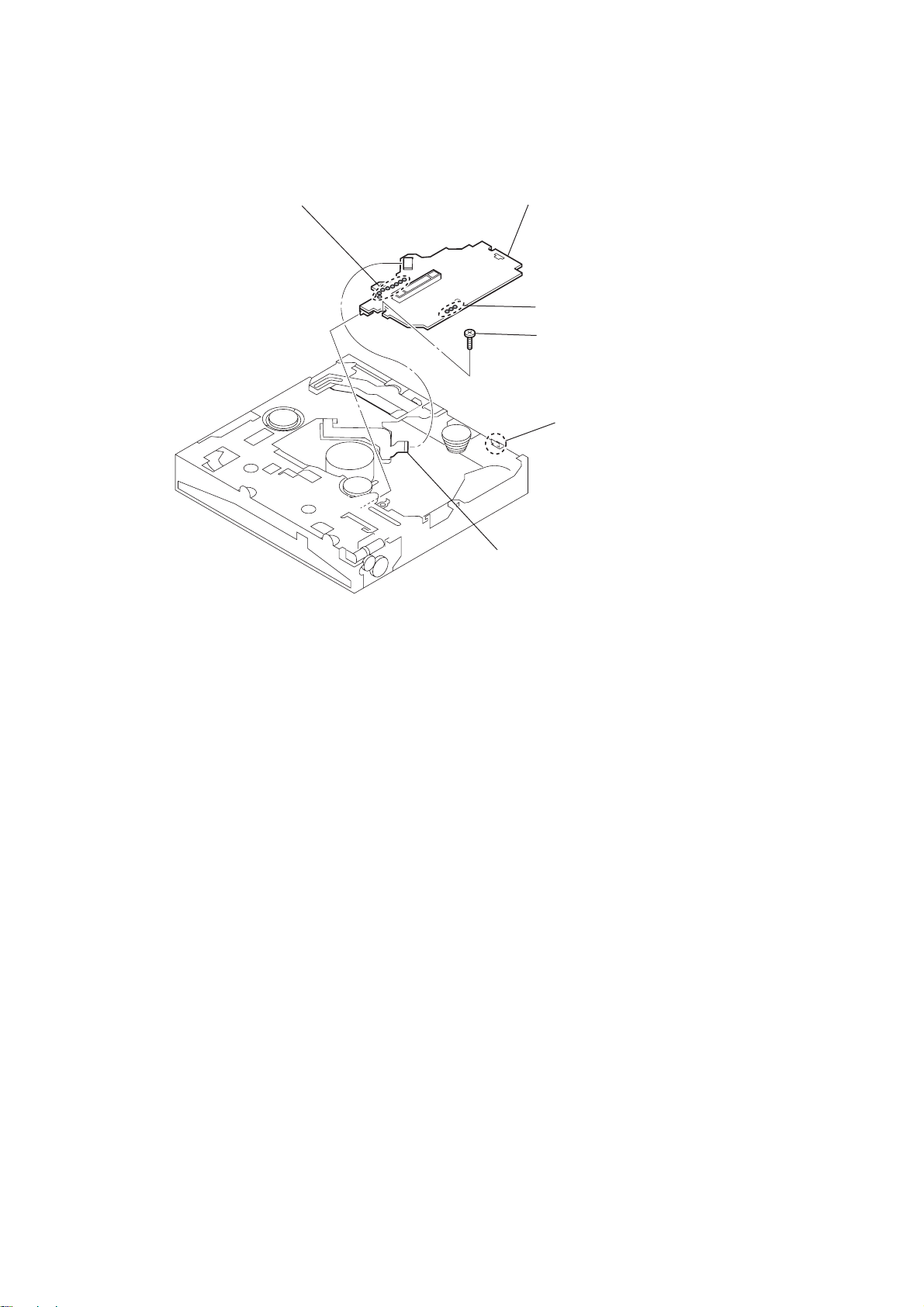
2-3. MAIN BOARD
3
MAIN board
1
three screws
(+BTT
2.6
× 5)
4
CN301
1
screw
(+PTT 2.6
2
two
(+PTT 2.6
×
6
screws
×
8
10
insulating sheet
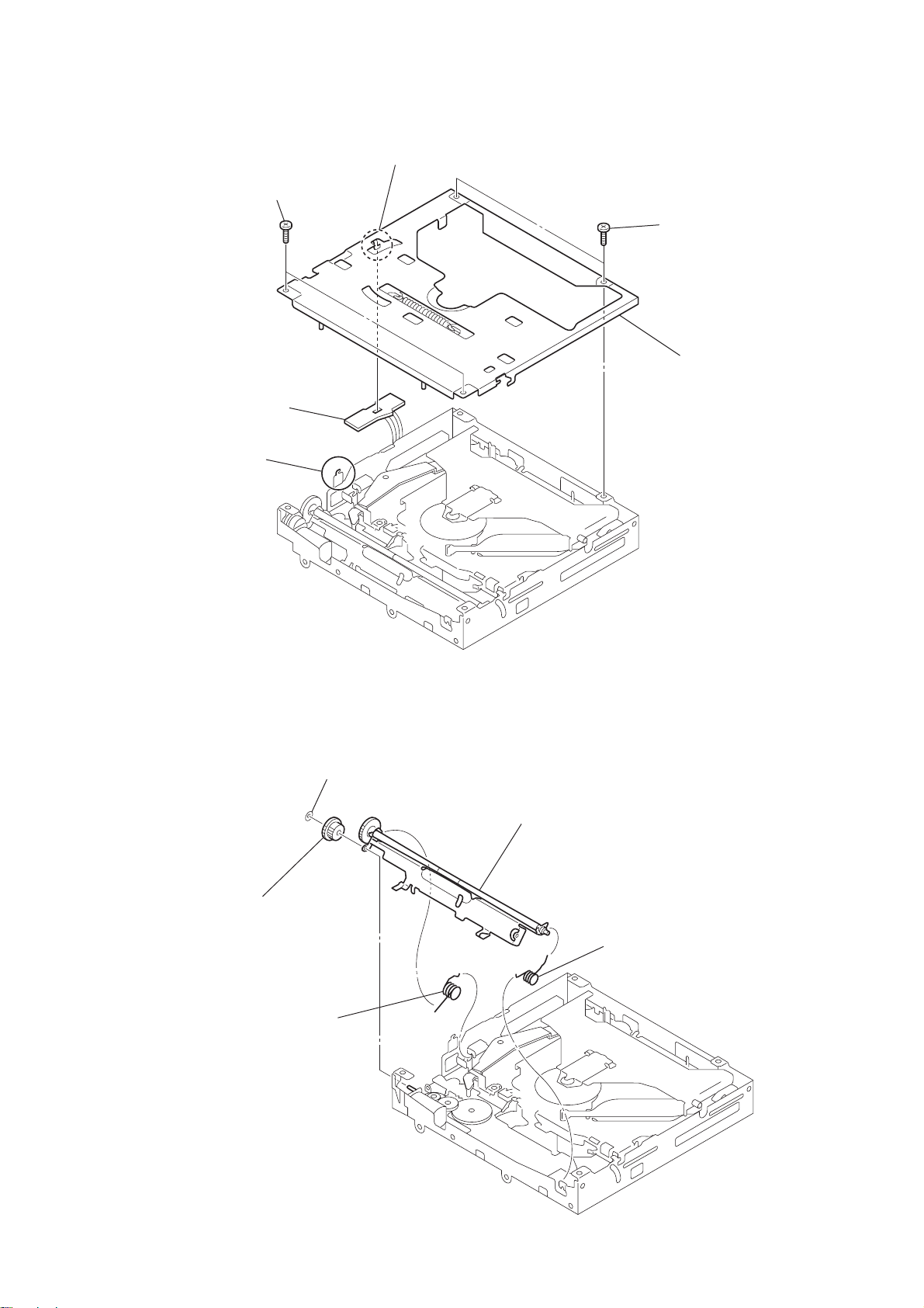
2-4. CHASSIS (T) SUB ASSY
2
two
screws
×
(+P 1.7
5
SENSOR board
3
claw
2.2)
4
claw
1
two
screws
(+P 1.7
×
2.2)
6
chassis (T) sub assy
CDX-S22/S22S
2-5. ROLLER ARM ASSY
4
gear (RA1)
1
spring (RAL-B)
3
washer
5
roller arm assy
2
spring (RAR-B)
11
CDX-S22/S22S
)
)
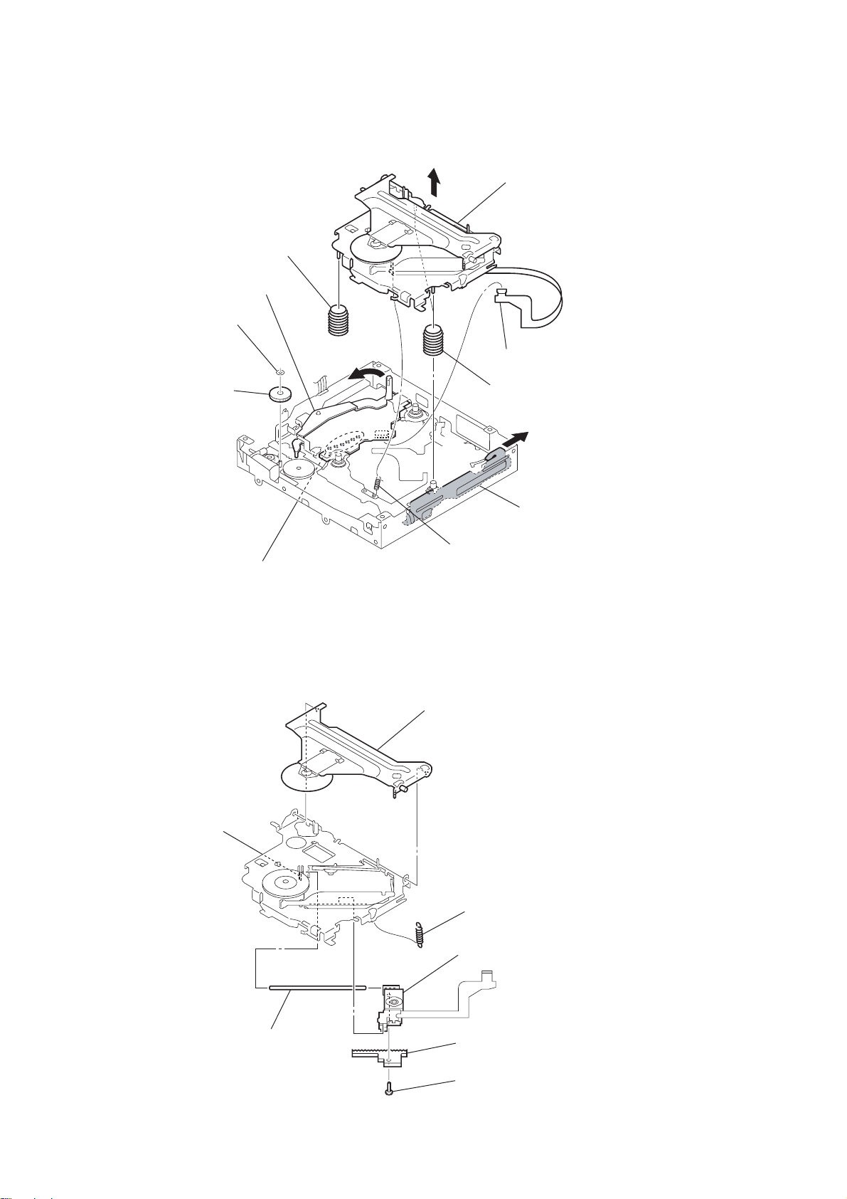
2-6. CHASSIS (OP) ASSY
0
coil spring (damper)
4
washer
5
gear (LE1)
lever (D)
6
8
qa
chassis (OP) assy
1
optical pick-up (CN1)
9
two coil springs (damper
7
2-7. OPTICAL PICK-UP
5
claw
2
Remove the six solders.
3
tension spring (KF60)
2
chucking arm sub assy
1
tension coil spring (CHKG
slider (R)
12
6
main shaft
7
optical pick-up
4
rack (SL)
3
screw
(+B 1.4
×
5)
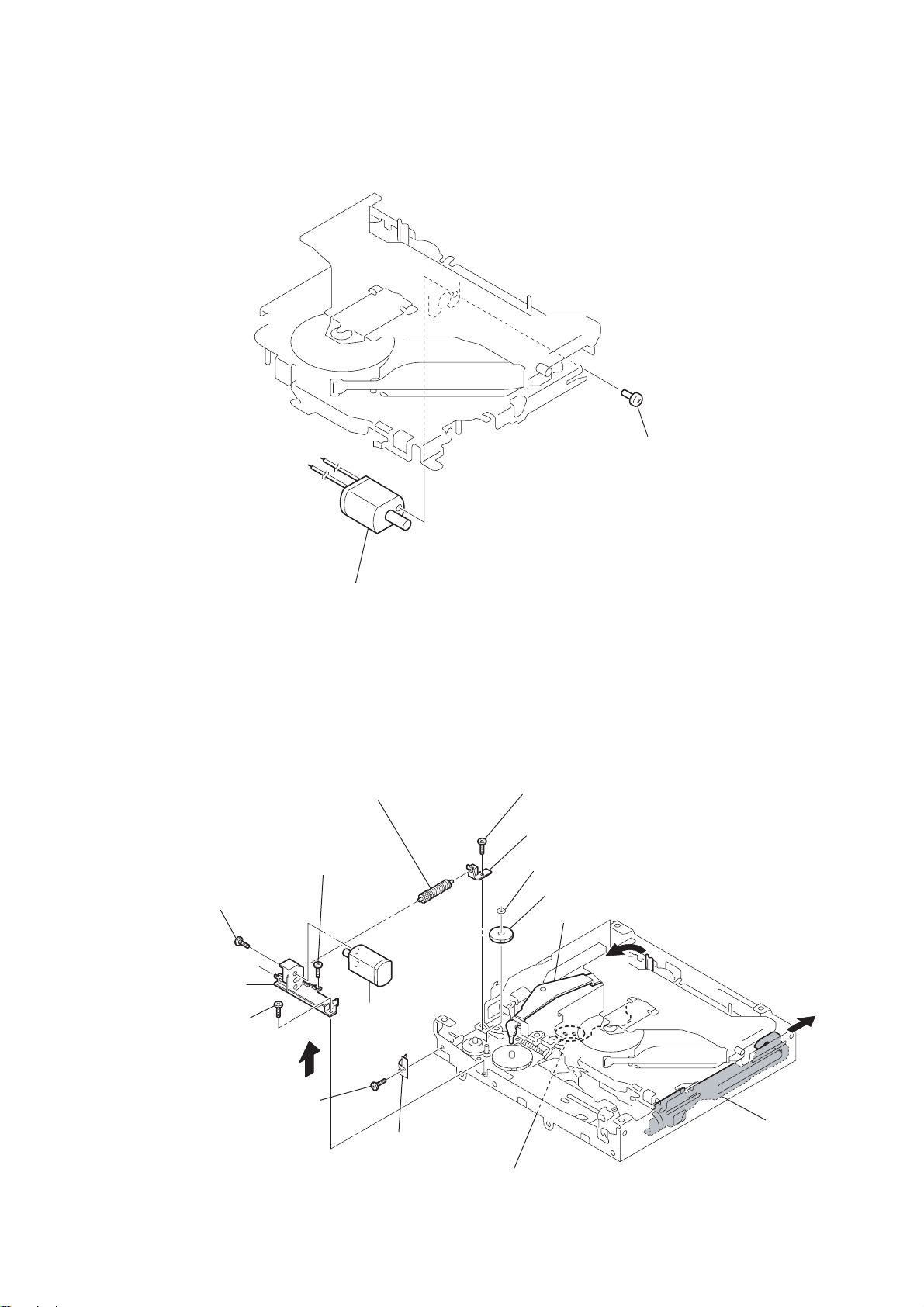
2-8. SL MOTOR ASSY (M902)
1
screw
(+P 1.4
CDX-S22/S22S
×
1.8)
2-9. LE MOTOR ASSY (M903)
qf
two toothed lock
(+M 1.4
bracket (LEM-N)
qs
screw
(+M 1.7
)
×
2.5)
screws
qd
2
qa
screw
(+M 1.7
SL motor assy (M902)
0
gear (LE) assy
×
2.5)
qg
LE motor assy
(M903)
8
screw
(+M 1.7
9
bearing (LEB-N)
2
washer
gear (LE1)
3
lever (D)
×
2.5)
4
5
6
screw
(+P 1.7
×
2.2)
7
leaf spring (LE)
1
Remove the solders.
slider (R)
13
CDX-S22/S22S
2-10. SERVO BOARD
1
Remove the eight solders.
6
SERVO board
2
Remove the three solders.
4
screw
5
claw
3
optical pick-up (CN1)
14
CDX-S22/S22S
MAIN
SECTION
(Page 16)
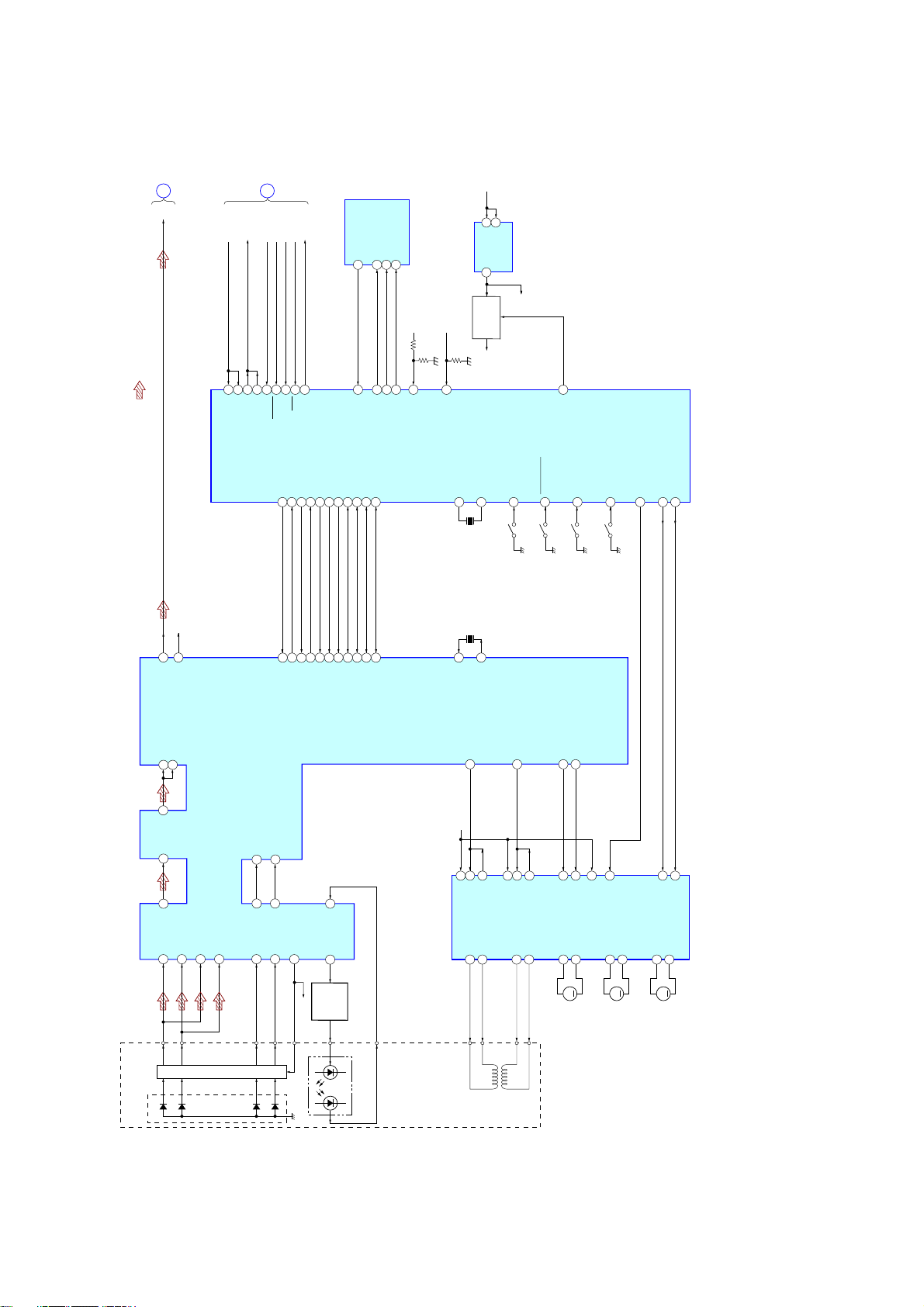
A
CD-L
UNI SI
: CD
• Signal Path
• R-ch is omitted due to same as L-ch.
R-CH
56
UNISI
MAIN
SECTION
(Page 16)
B
UNI SO
25
57
26
TXD
RXD
UNISO
UNI CLK
58
UNICKI
BUS ON
B/U CHECK
50
51
BU_IN
BUS_ON
DEC_XMUTE30DEC_INT
37
A ATT
SYS RST
75
60
RSTX
A_ATT
DEC_SSTBY15CD_ZDET14CD_XRST13CD_XCCE
27
IC501 (1/3)
EJECT_OK_SW
SYSTEM CONTROL
89
61
EJECT_OK
CD_BUCK11CD_BUS3
CD_BUS2
CD_BUS1
8
12
10
CD_ON
CDM_ON99Z-MUTE
98
93
63
64
66
CDON
ZMUTE
MECON
CD
CD_BUS0
7
MECHA+6V
67
MECON_CHK
IC3
SYSTEM CONTROL
+1.5V REG
SERVO+3.3V
68
CDON_CHK
81X180
X1
X2
IC6
+1.5V ON/OFF
X0
12MHz
16.934MHz
BU+3.3V
15
3
CE
VDD
VOUT
Q2,3
SWITCH
+1.5V
+1.5V
1.5V_ON
1
CDON_1500MV
MEC_SELFSW45MEC_INSW42MEC_LIMIT
MEC_DSW
53
46
SW2
SW1
(SELF)
(DOWN)
SW3
(DISC IN)
SW4
(LIMIT)
DRVON
6
MEC LOAD
MEC EJECT
43
44
30LO27
RO
RFI
RFRPI
81
82
83
RFEQO
AGCI
88
89
RFO
PD2
PD2
DETECTOR
FPI2
PD1
PD1
SECTION 3
DIAGRAMS
3-1. BLOCK DIAGRAM — CD SECTION —
FNI2
FPI1
949695
97
IC2
RF AMP,DIGITAL SERVO,
DIGITAL SIGNAL PROCESSOR
TEZI
RFZI
7
2
3
6
TEI
RFRP
TNI
FNI1
I-V AMP
TPI
98
100
F
E
F
E
51
PIO348PIO0
VC
58
36
ZDET
MSTBY
VRO
84
VC
LASER DIODE
37
43
/CCE
/RST
92
MDI
LDO
91
POWER
CONTROL
AUTOMATIC
LD
42
41
40
BUS3(SI)
BUCK(CLK)
Q21
PD LD
39
BUS1
BUS2(SO)
MON OUT
38
BUS0
23
XI
VC
27
OPIN4+
IC1
MOTOR DRIVE
SLED/SPINDLE/LOADING
FOCUS/TRACKING COIL DRIVE,
FCS+
OPTICAL
(KSS1000E)
PICK-UP BLOCK
2-AXIS DEVICE
F0O
9
26
OPIN4–
VO4–
16
24
XO
25
OPOUT4
VO4+
15
FCS–
(FOCUS)
TRO
10
23
24
OPIN3–
OPIN3+
VO3–
18
TRK+
TRK–
(TRACKING)
22
OPOUT3
VO3+
17
FMO
12
4
OPOUT1
VO1+
14
M
M902
DMO
13
7
OPOUT2
VO1–
13
(SLED)
20
BIAS
21
MUTE
VO2+
12
M901
VO2–
11
M
(SPINDLE)
LOAD
VOL+
10
M903
1
FWD
EJECT
28
REV
VOL–
9
M
(LOADING)
15 15
CDX-S22/S22S
 Loading...