

Sony CDXS-2210-X Service manual
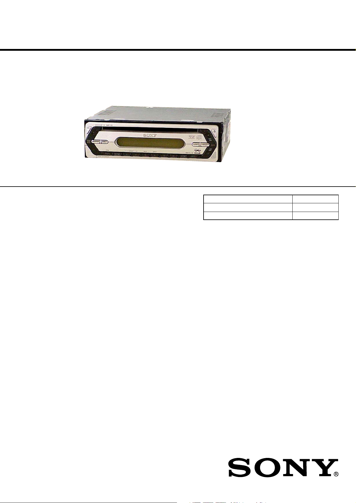
CDX-S2210/S2210S/S2210X/
S2250EE/SW330
SERVICE MANUAL
Ver. 1.3 2005. 11
Photo: CDX-S2250EE
• The tuner and CD sections have no adjustments.
AUDIO POWER SPECIFICATIONS (US Model)
POWER OUTPUT AND TOTAL HARMONIC DISTORTION
23.2 watts per channel minimum continuous average power into
4 ohms, 4 channels driven from 20 Hz to 20 kHz with no more
than 5% total harmonic distortion.
SPECIFICATIONS
CD player section
Signal-to-noise ratio 120 dB
Frequency response 10 – 20,000 Hz
Wow and flutter Below measurable limit
Tuner section
FM
Tuning range US, Canadian Model:
87.5 – 107.9 MHz
E model:
FM tuning interval:
50 kHz/200 kHz
switchable
87.5 – 108 MHz (at 50 kHz step)
87.5 – 107.9 MHz (at 200 kHz step)
East European Model:
FM1/FM2: 87.5 – 108.0 MHz (at 50 kHz step)
FM3: 65 – 74 MHz (at 30 kHz step)
Antenna terminal External antenna connector
Intermediate frequency 10.7 MHz/450 kHz
Usable sensitivity 9 dBf
Selectivity 75 dB at 400 kHz
Signal-to-noise ratio 67 dB (stereo),
69 dB (mono)
Harmonic distortion at 1 kHz
0.5% (stereo),
0.3% (mono)
Separation 35 dB at 1 kHz
Frequency response 30 – 15,000 Hz
US Model
CDX-S2210/SW330
Canadian Model
CDX-S2210
E Model
CDX-S2210S/S2210X
East European Model
CDX-S2250EE
Model Name Using Similar Mechanism NEW
CD Drive Mechanism Type MG-611TA-186//K
Optical Pick-up Name KSS1000E
AM
Tuning range US, Canadian Model:
530 – 1,710 kHz
E Model:
AM tuning interval:
9 kHz/10 kHz switchable
531 – 1,602 kHz (at 9 kHz step)
530 – 1,710 kHz (at 10 kHz step)
East European Model:
531 – 1,602 kHz
Antenna terminal External antenna connector
Intermediate frequency 10.7 MHz/450 kHz
Sensitivity 30 µV
Power amplifier section
Outputs Speaker outputs
(sure seal connectors)
Speaker impedance 4 – 8 ohms
Maximum power output Except East European model:
52 W × 4 (at 4 ohms)
East European model:
50 W × 4 (at 4 ohms)
General
Outputs Audio outputs terminal (sub/rear switchable)
Power antenna relay control terminal
Power amplifier control terminal
Inputs Antenna input terminal
Remote controller input terminal (CDX-S2210C only)
– Continued on next page –
9-879-323-04
2005K04-1
© 2005. 11
FM/AM COMPACT DISC PLAYER
Sony Corporation
eVehicle Division
Published by Sony Engineering Corporation
1
CDX-S2210/S2210S/S2210X/S2250EE/SW330
Tone controls Low: ±10 dB at 60 Hz (XPLOD)
Mid: ±10 dB at 1 kHz (XPLOD)
High: ±10 dB at 10 kHz (XPLOD)
Power requirements 12 V DC car battery
(negative ground)
Dimensions Approx. 178 × 50 × 178 mm
(7 1/8 × 2 × 7 1/8 in.) (w/h/d)
Mounting dimensions Approx. 182 × 53 × 161 mm
(7 1/4 × 2 1/8 × 6 3/8 in.) (w/h/d)
Mass Approx. 1.2 kg
(2 lb. 10 oz.)
Supplied accessories Card remote commander: RM-X151 (CDX-S2210S/SW330
only) Parts for installation and connections (1 set)
Front panel case (1)
Design and specifications are subject to change without
notice.
SERVICE NOTES
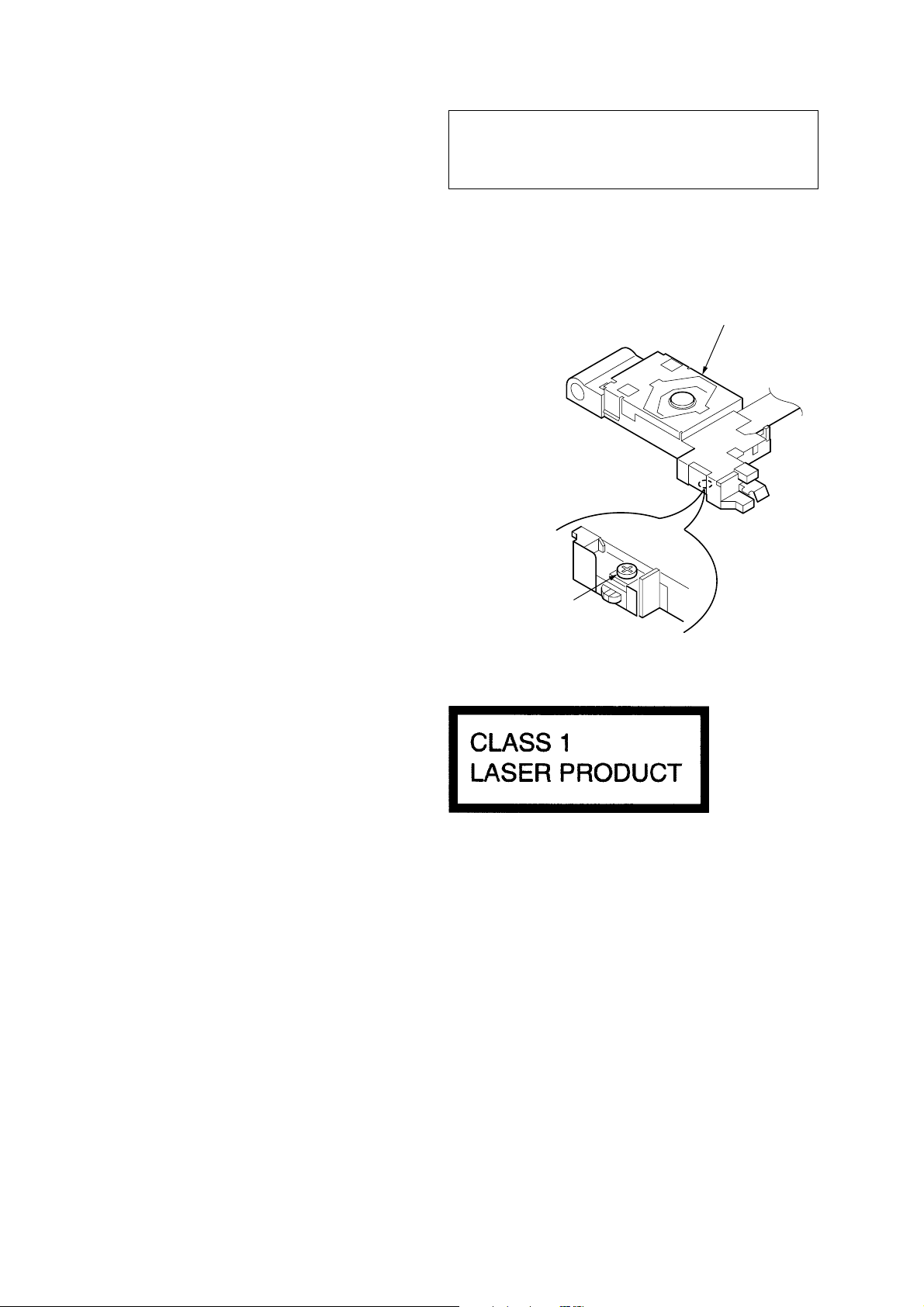
NOTES ON HANDLING THE OPTICAL PICK-UP BLOCK
OR BASE UNIT
The laser diode in the optical pick-up block may suffer electrostatic
breakdown because of the potential difference generated by the
charged electrostatic load, etc. on clothing and the human body.
During repair, pay attention to electrostatic breakdown and also use
the procedure in the printed matter which is included in the repair
parts.
The flexible board is easily damaged and should be handled with
care.
CAUTION
Use of controls or adjustments or performance of procedures
other than those specified herein may result in hazardous
radiation exposure.
If the optical pick-up block is defective, please replace the whole
optical pick-up block.
Never turn the semi-fixed resistor located at the side of optical
pick-up block.
optical pick-up
semi-fixed resistor
NOTES ON LASER DIODE EMISSION CHECK
The laser beam on this model is concentrated so as to be focused on
the disc reflective surface by the objective lens in the optical pickup block. Therefore, when checking the laser diode emission, observe from more than 30 cm away from the objective lens.
Notes on Chip Component Replacement
• Never reuse a disconnected chip component.
• Notice that the minus side of a tantalum capacitor may be dam-
aged by heat.
TEST DISCS
This set can playback CD-R and CD-ROM discs. The following
test discs should be used to check the capability:
CD-R test disc TCD-R082LMT (Part No. J-2502-063-1)
CD-RW test disc TCD-W082L (Part No. J-2502-063-2)
• E, East European Model
This label is located on the bottom of the chassis.
SAFETY-RELATED COMPONENT WARNING!!
COMPONENTS IDENTIFIED BY MARK 0 OR DOTTED LINE
WITH MARK 0 ON THE SCHEMATIC DIAGRAMS AND IN
THE PARTS LIST ARE CRITICAL TO SAFE OPERATION.
REPLACE THESE COMPONENTS WITH SONY PARTS WHOSE
PART NUMBERS APPEAR AS SHOWN IN THIS MANUAL OR
IN SUPPLEMENTS PUBLISHED BY SONY.
2
ATTENTION AU COMPOSANT AYANT RAPPORT
À LA SÉCURITÉ!!
LES COMPOSANTS IDENTIFIÉS PAR UNE MARQUE 0 SUR LES
DIAGRAMMES SCHÉMATIQUES ET LA LISTE DES PIÈCES
SONT CRITIQUES POUR LA SÉCURITÉ DE FONCTIONNEMENT.
NE REMPLACER CES COMPOSANTS QUE PAR DES PIÈCES
SONY DONT LES NUMÉROS SONT DONNÉS DANS CE MANUEL
OU DANS LES SUPPLÉMENTS PUBLIÉS PAR SONY.
CDX-S2210/S2210S/S2210X/S2250EE/SW330
D
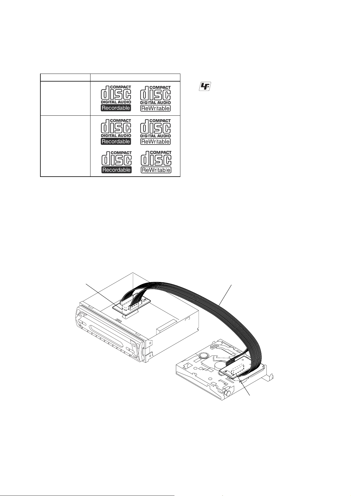
• CD Playback:
You can play CD-DA (also containing CD TEXT*1), CD-R/CDRW (MP3 files also containing Multi Session and ATRAC CD
(ATRAC3 and ATRAC3plus format).
Type of discs Label on the disc
CD-DA
MP3
ATRAC CD
*1 A CD TEXT disc is a CD-DA that includes information such as
disc, artist and track name.
EXTENSION CABLE AND SERVICE POSITION
When repairing or servicing this set, connect the jig (extension cable)
as shown below.
z
UNLEADED SOLDER
Boards requiring use of unleaded solder are printed with the lead
free mark (LF) indicating the solder contains no lead.
(Caution: Some printed circuit boards may not come printed with
the lead free mark due to their particular size.)
: LEAD FREE MARK
Unleaded solder has the following characteristics.
• Unleaded solder melts at a temperature about 40°C higher than
ordinary solder.
Ordinary soldering irons can be used but the iron tip has to be
applied to the solder joint for a slightly longer time.
Soldering irons using a temperature regulator should be set to
about 350°C.
Caution: The printed pattern (copper foil) may peel away if the
heated tip is applied for too long, so be careful!
• Strong viscosity
Unleaded solder is more viscous (sticky, less prone to flow)
than ordinary solder so use caution not to let solder bridges
occur such as on IC pins, etc.
• Usable with ordinary solder
It is best to use only unleaded solder but unleaded solder may
also be added to ordinary solder.
• Connect the MAIN board (CNP301) and the SERVO board (CN2)
with the extension cable (Part No. J-2502-076-1).
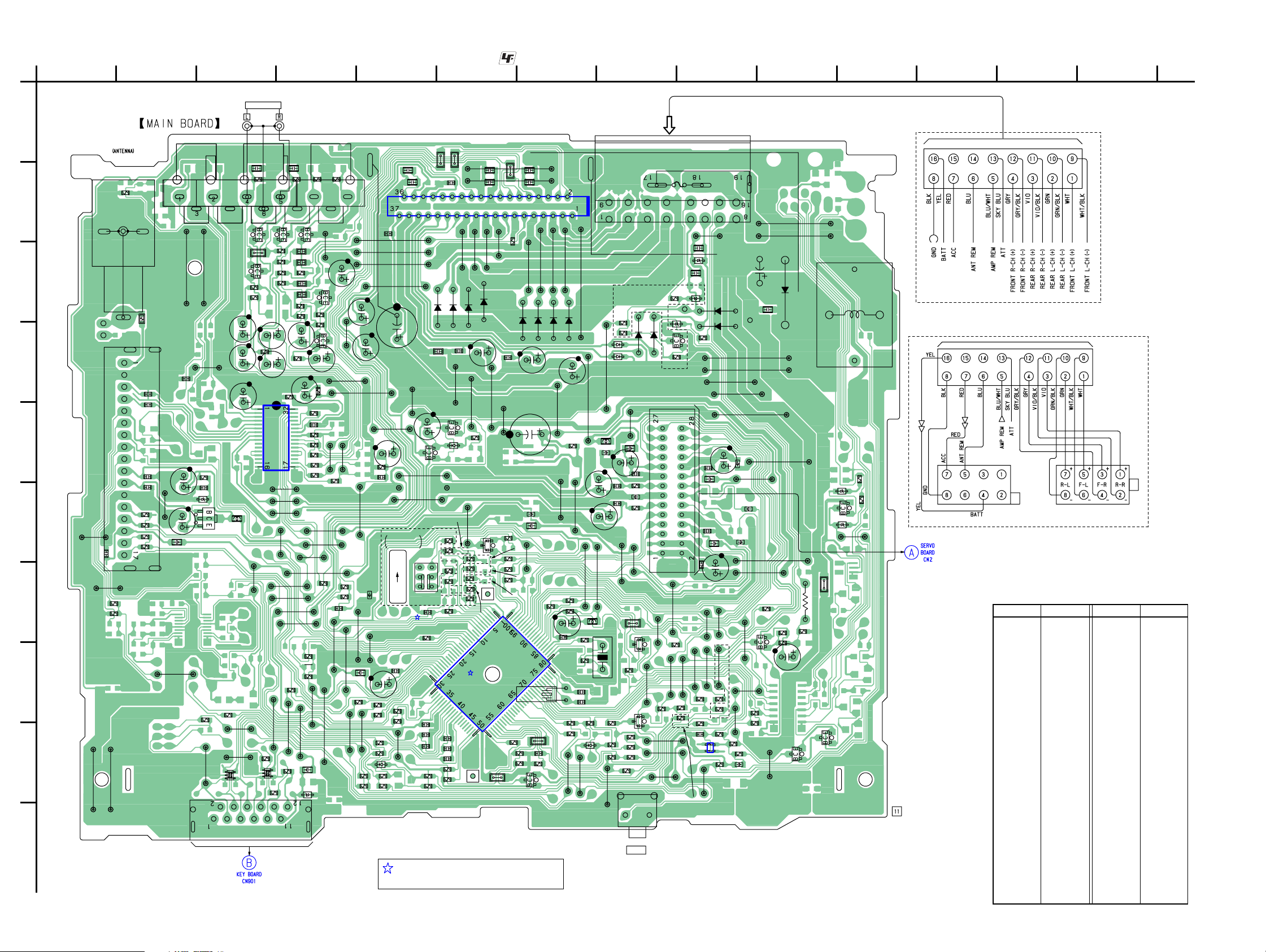
MAIN BOARD
CNP301
J-2502-076-1
SERVO BOAR
CN2
3

CDX-S2210/S2210S/S2210X/S2250EE/SW330
TABLE OF CONTENTS
1. GENERAL
Location of controls and basic operations (CDX-S2210) ....... 5
Location of controls and basic operations (CDX-S2250EE) .. 5
Location of controls and basic operations
(CDX-S2210S/S2210X) .......................................................... 5
Location of controls and basic operations (CDX-SW330) ..... 6
Connections (CDX-S2210) ..................................................... 7
Connections (CDX-S2210S/S2210X) ..................................... 8
Connections (CDX-S2250EE) ................................................ 9
Connections (CDX-SW330).................................................. 10
2. DISASSEMBLY
2-1. Sub Panel (LCD) Assy ...................................................... 11
2-2. CD Mechanism Block ....................................................... 12
2-3. Main Board ....................................................................... 12
2-4. Chassis (T) Sub Assy ........................................................ 13
2-5. Roller Arm Assy ................................................................ 13
2-6. Chassis (OP) Assy ............................................................. 14
2-7. Optical Pick-up ................................................................. 14
2-8. SL Motor Assy (M902) ..................................................... 15
2-9. LE Motor Assy (M903)..................................................... 15
2-10. Servo Board ....................................................................... 16
3. DIAGRAMS
3-1. Block Diagram –CD Section– ........................................... 17
3-2. Block Diagram –Main Section– ........................................ 18
3-3. Block Diagram –Display Section– .................................... 19
3-4. Printed Wiring Boards –SERVO Board– .......................... 21
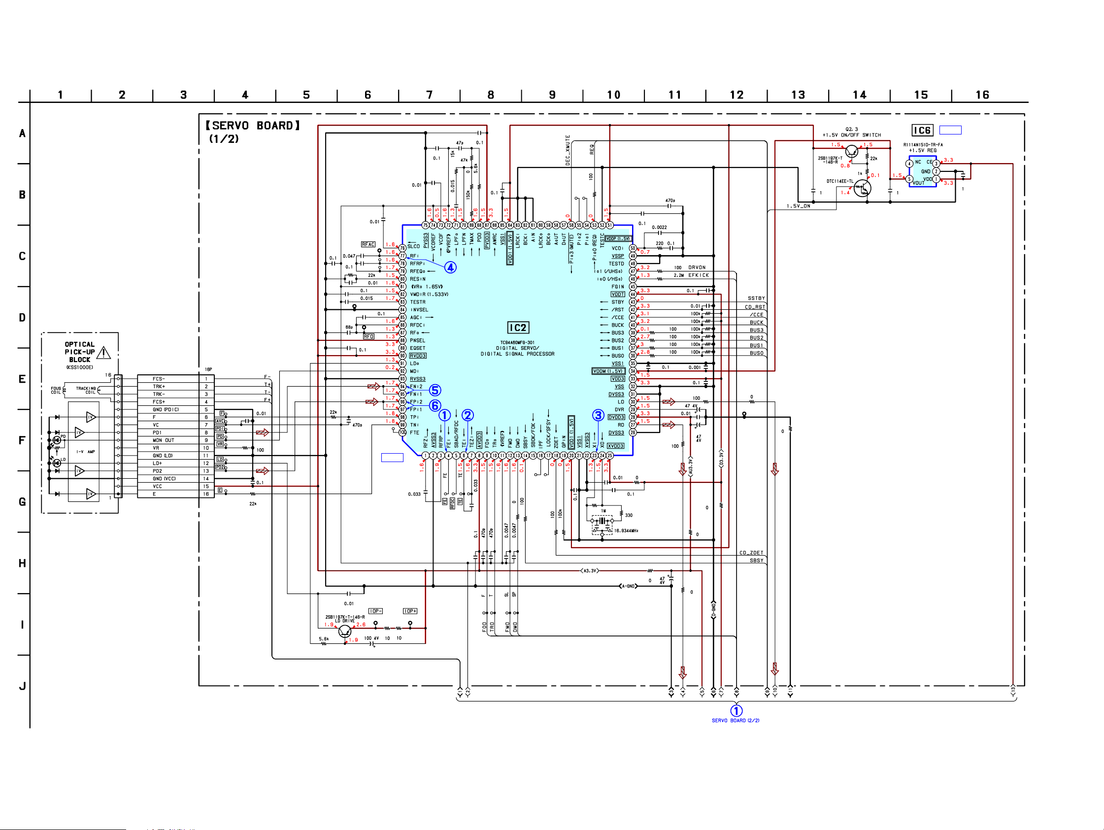
3-5. Schematic Diagram –SERVO Board (1/2)– ...................... 22
3-6. Schematic Diagram –SERVO Board (2/2)– ...................... 23
3-7. Printed Wiring Board –Main Board– ................................ 24
3-8. Schematic Diagram –Main Board (1/4)– .......................... 25
3-9. Schematic Diagram –Main Board (2/4)– .......................... 26
3-10. Schematic Diagram –Main Board (3/4)– .......................... 27
3-11. Schematic Diagram –Main Board (4/4)– .......................... 28
3-12. Printed Wiring Board –KEY Board– ................................ 29
3-13. Schematic Diagram –KEY Board– ................................... 30
4. EXPLODED VIEWS
4-1. Main Section ..................................................................... 39
4-2. Front Panel Section ........................................................... 40
4-3. CD Mechanism Section (1) (MG-611TA-186//K) ............ 41
4-4. CD Mechanism Section (2) (MG-611TA-186//K) ............ 42
4-5. CD Mechanism Section (3) (MG-611TA-186//K) ............ 43
4-6. CD Mechanism Section (4) (MG-611TA-186//K) ............ 44
5. ELECTRICAL PARTS LIST......................................... 45
4
SECTION 1
GENERAL
CDX-S2210/S2210S/S2210X/S2250EE/SW330
This section is extracted
from instruction manual.
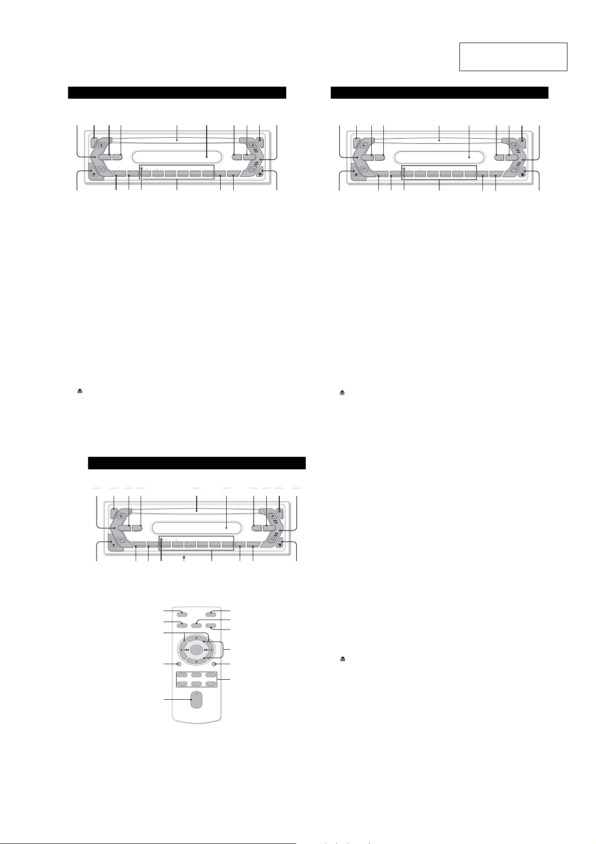
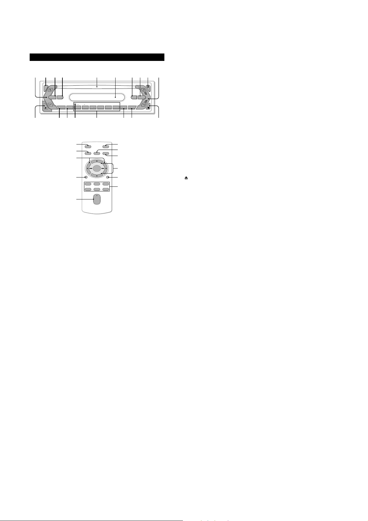
Location of controls and basic operations
Main unit
(CDX-S2210) (CDX-S2250EE)
1234 5 6 7890
SEL
SOURCE MODE
qa
DIM
qs qd qg qh qj qkqf
GROUP
–
SENS BTM OFFDSPL 1 2 3 4 5 6
Refer to the pages listed for details.
a Volume +/– button
To a djus t volume.
b SEL (select) button 4, 7
To s elect items.
c SOURCE button
To p ower on/change the source (Radio/CD).
d MODE button 6
To s elect the r adio band (FM/AM).
e Disc slot
Insert the disc (label side up), playback
starts.
f Display window
g ATT (attenuate) button
To a ttenuate t he sound. To cancel, press
again.
h EQ3 (equalizer) button 7
To s elect an equalizer type (XPLOD,
VOCAL, CLUB, JAZZ, NEWAGE, ROCK,
CUSTOM or OFF).
i Z (eject) button
To e ject the disc.
j SEEK +/– button
Radio:
To t une in stations automatically (press); find
a station manually (press an d hold).
CD:
To s kip tracks (press); skip tracks
continuously (press, t hen press again within
about 1 second and hold); fast- forward/
reverse a track (press and hold).
k (front panel release) button 4
SHUFREP
+
l DSPL (display)/DIM (dimmer) button
4, 6
To c hange display items (press); change the
display brightness (press and hold).
m SENS button
To improve weak reception: LOCAL/
MONO.
n RESET button (located behind the front
panel) 4
o Number buttons
Radio:
To r ecei ve stored stations (p ress); store
stations (press and hold).
CD:
(1)/(2): GROUP* –/+
To s kip g roups (press); skip groups
continuously (press and hold).
(3): REP 6
(4): SHUF 6
p BTM button 6
To s tart the BTM function (pr ess and hold).
q OFF button
To p ower off/stop the source.
r Receptor for the card remote
commander 8
*
When an MP3/ATRAC CD is played.
EQ3AT T
CDX-S2210
SEEK
Location of controls and basic operations
Main unit
1234 5 6 7890
SEL
SOURCE MODE
qa
DIM
qs qd qg qh qj qkqf
GROUP
–
SENS BTM OFFDSPL 1 2 3 4 5 6
Refer to the pages listed for details.
a Volume +/– button
To a djus t volume.
b SEL (select) button 4, 7
To s elect items.
c SOURCE button
To p ower on/change the source (Radio/CD).
d MODE button 6
To s elect the r adio band (FM/AM).
e Disc slot
Insert the disc (label side up), playback
starts.
f Display window
g ATT (attenuate) button
To a ttenuate t he sound. To cancel, press
again.
h EQ3 (equalizer) button 7
To s elect an equalizer type (XPLOD,
VOCAL, CLUB, JAZZ, NEWAGE, ROCK,
CUSTOM or OFF).
i Z (eject) button
To e ject the disc.
j SEEK +/– button
Radio:
To t une in stations automatically (press); find
a station manually (press an d hold).
CD:
To s kip tracks (press); skip tracks
continuously (press, t hen press again within
about 1 second and hold); fast- forward/
reverse a track (press and hold).
k (front panel release) button 4
SHUFREP
+
l DSPL (display)/DIM (dimmer) button
4
To c hange display items (press); change the
display brightness (press and hold).
m SENS button
To improve weak reception: LOCAL/
MONO.
n RESET button (located behind the front
panel) 4
o Number buttons
Radio:
To r ecei ve stored stations (p ress); store
stations (press and hold).
CD:
(1)/(2): GROUP* –/+
To s kip g roups (press); skip groups
continuously (press and hold).
(3): REP 6
(4): SHUF 6
p BTM button 6
To s tart the BTM function (pr ess and hold).
q OFF button
To p ower off/stop the source.
r Receptor for the card remote
commander 8
*
When an MP3/ATRAC CD is played.
SEEK
EQ3AT T
CDX-S2250EE
Location of controls and basic operations
Main unit
Card remote commander RM-X151
(CDX-S2210S only)
(CDX-S2210S/S2210X)
1234 5 6 7890
1234 5 6 7890
SEL
SEL
SEEK
SEEK
EQ3AT T
EQ3AT T
CDX-S2210X
CDX-S2210X
CDX-S2210S
CDX-S2210S
CDX-S2210C
CDX-S2210C
ql
ql
qa
qa
SOURCE MODE
SOURCE MODE
DIM
DIM
SENS BTM OFFDSPL 1 2 3 4 5 6
SENS BTM OFFDSPL 1 2 3 4 5 6
qs qd qg qh qj qkqf
qs qd qg qh qj qkqf
qk
3
w;
qs
wa
SHUFREP
SHUFREP
+
+
GROUP
GROUP
–
–
OFF
SOURCE
DSPL
132
465
SEL
)
+
–
+
VOL
–
7
AT T
2
MODE
4
ws
SCRL
wd
wf
Refer to the pages listed for details. The
corresponding buttons on the car d remote
commander control the sa me functions as those
on the unit.
a Volume +/– button
To a djus t vol ume .
b SEL (select) button 4, 9
To s elect items.
c SOURCE button
To p ower on/change the source (Radio/CD).
d MODE button 8
To s elect the r adio band (FM/AM).
e Disc slot
Insert the disc (label side up), playback
starts.
f Display window
g ATT (attenuate) button
To a ttenuate t he sound. To cancel, press
again.
h EQ3 (equalizer) button 9
To s elect an equ alizer type (XPLOD,
VOCA L, CLUB, JAZZ, NEWAGE, ROCK,
CUSTOM or OFF).
i Z (eject) button
To e ject the disc.
j SEEK +/– button
Radio:
To t une in stations automatically (press); find
a station manually (press an d hold).
CD:
To s kip tracks (press); skip tracks
continuously (press, t hen press again within
about 1 second and hold); fast- forward/
reverse a track (press and hold).
k (front panel release) button 4
l DSPL (display)/DIM (dimmer) button
4, 8
To c hange display items (press); chang e the
display brightness (pr ess and hold).
m SENS button
To i mpro ve we ak reception : LOCAL/
MONO.
n RESET button (located behind the front
panel) 4
o Frequency select switch (located on the
bottom of the unit)
See “Frequency select switch” in the
supplied installation/connections manual.
p Number buttons
Radio:
To r ecei ve stored stations (press); store
stations (press and hold).
CD:
(1)/(2): GROUP* –/+
To s kip g rou ps (press); skip groups
continuously (press and hold).
(3): REP 8
(4): SHUF 8
q BTM button 8
To s tart the B TM f unction (press and hold).
r OFF button
To p ower off/stop the source.
s Receptor for the card remote
commander 10
The following buttons on the card remote
commander have also different buttons/functions
from the unit.
t < (.)/, (>) buttons
To c ontrol radio/CD, the same as (SEEK)
+/– on the unit. (For details of other
operations, see “With the card remote
commander” on each pages.)
u VOL +/– button
To a djust volume.
v M (+)/m (–) buttons
To c ontrol CD, the same as (1)/(2) –/+ on
the unit. (For details of other operatio ns, see
“With the card remote commander” on each
pages.)
w SCRL button
To s croll the display item.
x Number buttons
To r ecei ve stored stations (press); store
stations (press and hol d).
*
When an MP3/ATRAC CD is played.
Note
If the unit is turned off and the display disappea rs, it
cannot be operated with the car d remote commander
(SOURCE)
unless
inserted to activate the unit first.
Tip
For details on how to replace the battery, see
“Replacing the lithium battery of the card remote
commander” on page 13.
on the unit is pressed, or a disc is
5
CDX-S2210/S2210S/S2210X/S2250EE/SW330
Location of controls and basic operations
Main unit
(CDX-SW330)
1234 5 6 7890
SEL
EQ3AT T
CDX-SW330
SEEK
qk
qa
SOURCE MODE
DIM
SENS BTM OFFDSPL 1 2 3 4 5 6
qs qd qg qh qjqf
GROUP
–
SHUFREP
+
Card remote commander RM-X151
qj
3
ql
qs
w;
OFF
SOURCE
DSPL
132
465
SEL
+
–
+
VOL
–
7
AT T
2
MODE
4
wa
SCRL
ws
wd
Refer to the pages listed for details. The
corresponding buttons on the card remote
commander control the same functions as those
on the unit.
a Volu me +/– button
To adjust volume.
b SEL (select) button 4, 9, 9, 9
To s elect items.
c SOURCE button
To power on/change the source (Radio/CD).
d MODE button 8
To select the radio band (FM/AM).
e Disc slot
Insert the disc (label side up), playback
starts.
f Display window
g ATT ( attenuate) button
To attenuate the sound. To cancel, press
again.
h EQ3 (equalizer) button 9
To select an equalizer type (XPLOD,
VOCAL , CLUB, JAZZ, NEWAGE, ROCK,
CUSTOM or OFF).
i Z (eject) button
To e ject the disc.
j SEEK +/– button
Radio:
To tune in stations automatically (press); find
a station manually (press and hold).
CD:
To skip tracks (press); skip tracks
continuously (press, then press again within
about 1 second and hold); fast-forward/
reverse a track (press and hold).
k (front panel release) button 4
l DSPL (display)/DIM (dimmer) button
4, 8
To change display items (press); change the
display brightness (press and hold).
m SENS button
To improve weak reception: LOCAL/
MONO.
n RESET button (located behind the front
panel) 4
o Number buttons
Radio:
To receive stored stations (press); store
stations (press and hold).
CD:
(1)/(2): GROUP* –/+
To skip groups (press); skip groups
continuously (press and hold).
(3): REP 8
(4): SHUF 8
p BTM button 8
To start the BTM function (press and hold).
q OFF button
To p ower off/stop the source.
r Receptor for the card remote
commander
The following buttons on the card remote
commander have also different buttons/functions
from the unit.
s < (.)/, (>) buttons
To control radio/CD, the same as (SEEK)
+/– on the unit. (For details of other
operations, see “With the card remote
commander” on each pages.)
t VOL +/– button
To adjust volume.
u M (+)/m (–) buttons
To c ontrol CD, the same as (1)/(2) –/+ on
the unit. (For details of other operations, see
“With the card remote commander” on each
pages.)
v SCRL button
To s croll the display item.
w Number buttons
To receive stored stations (press); store
stations (press and hold).
*
When an MP3/ATRAC CD is played.
Note
If the unit is turned off and the display disappears, it
cannot be operated with the card remote commander
(SOURCE)
unless
inserted to activate the unit first.
Tip
For details on how to replace the battery, see
“Replacing the lithium battery of the card remote
commander” on page 11.
on t
he unit is pressed, or a disc is
6
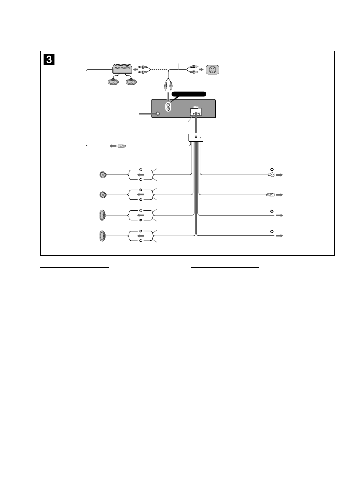
Connections (CDX-S2210)
from car antenna
à partir de l’antenne de la voiture
AUDIO OUT REAR
L
L
R
R
AUDIO
BUS
OUT
AUD
IO
IN
Fuse (10 A)
Fusible (10 A)
CDX-S2210/S2210S/S2210X/S2250EE/SW330
1
*
2
*
1
RCA pin cord (not supplied)
*
*2
AUDIO OUT can be switched to SUB
or REAR.
For details, see the supplied
operating instructions.
1
*
Cordon à broche RCA (non fourni)
*2
AUDIO OUT peut être commuté sur
SUB ou REAR.
Pour obtenir plus de détails, reportez-
us au mode d’emploi fourni.
vo
Left
Gauche
Right
Droit
Left
Gauche
Right
Droit
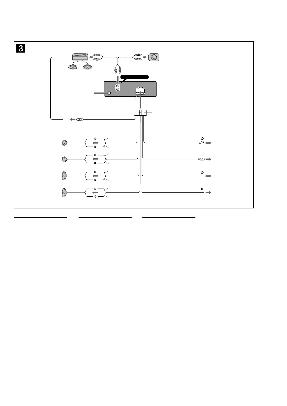
Connection diagram (3)
1 To a metal surface of the car
First connect the black ground lead, then connect the yellow
and red power input leads.
2 To the power antenna control lead or power
supply lead of antenna booster amplifi er
Notes
• It is not necessary to connect this lead if there is no power
antenna or antenna booster, or with a manually-operated
telescopic antenna.
• When your car has a built-in FM/AM antenna in the rear/
side glass, see “Notes on the control and power supply
leads.”
3 To AMP REMOTE IN of an optional power
amplifi er
This connection is only for amplifi ers. Connecting any other
system may damage the unit.
4 To the +12 V power terminal which is
energized in the accessory position of the
ignition key switch
Notes
• If there is no accessory position, connect to the +12 V
power (battery) terminal which is energized at all times.
Be sure to connect the black ground lead to a metal
surface of the car fi rst.
• When your car has a built-in FM/AM antenna in the rear/
side glass, see “Notes on the control and power supply
leads.”
5 To the +12 V power terminal which is
energized at all times
Be sure to connect the black ground lead to a metal surface
of the car fi rst.
AMP REM
3
Max. supply current 0.3 A
Courant max. fourni 0,3 A
Notes on the control and power supply leads
• The power antenna control lead (blue) supplies +12 V DC
when you turn on the tuner.
• When your car has built-in FM/AM antenna in the rear/side
glass, connect the power antenna control lead (blue) or the
accessory power input lead (red) to the power terminal of the
existing antenna booster. For details, consult your dealer.
• A power antenna without a relay box cannot be used with this
unit.
Memory hold connection
When the yellow power input lead is connected, power will
always be supplied to the memory circuit even when the ignition
switch is turned off.
Notes on speaker connection
• Before connecting the speakers, turn the unit off.
• Use speakers with an impedance of 4 to 8 ohms, and with
adequate power handling capacities to avoid its damage.
• Do not connect the speaker terminals to the car chassis, or
connect the terminals of the right speakers with those of the
left speaker.
• Do not connect the ground lead of this unit to the negative (–)
terminal of the speaker.
• Do not attempt to connect the speakers in parallel.
• Connect only passive speakers. Connecting active speakers
(with built-in amplifi ers) to the speaker terminals may damage
the unit.
• To avoid a malfunction, do not use the built-in speaker leads
installed in your car if the unit shares a common negative (–)
lead for the right and left speakers.
• Do not connect the unit’s speaker leads to each other.
Note on connection
If speaker and amplifi er are not connected correctly, “FAILURE”
appears in the display. In this case, make sure the speaker and
amplifi er are connected correctly.
Blue/white striped
Rayé bleu/blanc
White
Blanc
White/black striped
Rayé blanc/noir
Gray
Gris
Gray/black striped
Rayé gris/noir
Green
Ver t
Green/black striped
Rayé vert/noir
Purple
Mauve
Purple/black striped
Rayé mauve/noir
2
Black
Noir
Blue
Bleu
Max. supply current 0.1 A
Courant max. fourni 0,1 A
Red
Rouge
Ye l l o w
Jaune
Schéma de raccordement (3)
1 À un point métallique de la voiture
Branchez d’abord le câble de mise à la masse noir et,
ensuite, les câbles d’entrée d’alimentation jaune et rouge.
2 Vers le câble de commande d’antenne
électrique ou le câble d’alimentation de
l’amplifi cateur d’antenne
Remarques
• Il n’est pas nécessaire de raccorder ce câble s’il n'y a pas
d’antenne électrique ni d’amplifi cateur d’antenne, ou avec
une antenne télescopique manuelle.
• Si votre voiture est équipée d’une antenne FM/AM
intégrée dans la vitre arrière/latérale, voir « Remarques
sur les câbles de commande et d’alimentation ».
3 Au niveau de AMP REMOTE IN de
l’amplifi cateur de puissance en option
Ce raccordement s’applique uniquement aux amplifi cateurs.
Le branchement de tout autre système risque
d’endommager l’appareil.
4 À la borne +12 V qui est alimentée quand la
clé de contact est sur la position accessoires
Remarques
• S’il n’y a pas de position accessoires, raccordez la borne
d’alimentation (batterie) +12 V qui est alimentée en
permanence. Raccordez d’abord le câble de mise à la
masse noir à un point métallique du véhicule.
• Si votre voiture est équipée d’une antenne FM/AM
intégrée dans la vitre arrière/latérale, voir « Remarques
sur les câbles de commande et d’alimentation ».
5 À la borne +12 V qui est alimentée en
permanence
Raccordez d’abord le câble de mise à la masse noir à un
point métallique du véhicule.
1
ANT REM
2
4
5
Remarques sur les câbles de commande et d’alimentation
• Le câble de commande d’antenne électrique (bleu) fournit une
alimentation de + 12 V CC lorsque vous mettez la radio sous
tension.
• Lorsque votre voiture est équipée d’une antenne FM/AM
intégrée dans la vitre arrière/latérale, raccordez le câble de
commande d’antenne (bleu) ou l’entrée d’alimentation des
accessoires (rouge) à la borne d’alimentation de l’amplifi cateur
d’antenne existant. Pour plus de détails, consultez votre
détaillant.
• Une antenne électrique sans boîtier de relais ne peut pas être
utilisée avec cet appareil.
Raccordement pour la conservation de la mémoire
Lorsque le câble d’entrée d’alimentation jaune est raccordé, le
circuit de la mémoire est alimenté en permanence même si la clé
de contact est sur la position d’arrêt.
Remarques sur le raccordement des haut-parleurs
• Avant de raccorder les haut-parleurs, mettez l’appareil hors
tension.
• Utilisez des haut-parleurs ayant une impédance de 4 à 8 ohms
avec une capacité électrique adéquate pour éviter de les
endommager.
• Ne raccordez pas les bornes du système de haut-parleurs au
châssis de la voiture et ne raccordez pas les bornes des hautparleurs droit à celles du haut-parleur gauche.
• Ne raccordez pas le câble de mise à la masse de cet appareil
à la borne négative (–) du haut-parleur.
• N’essayez pas de raccorder les haut-parleurs en parallèle.
• Raccordez uniquement des haut-parleurs passifs. Le
raccordement de haut-parleurs actifs (avec amplifi cateurs
intégrés) aux bornes des haut-parleurs peut endommager
l’appareil.
• Pour éviter tout dysfonctionnement, n’utilisez pas les câbles
des haut-parleurs intégrés installés dans votre voiture si
l’appareil partage un câble négatif commun (–) pour les hautparleurs droit et gauche.
• Ne raccordez pas entre eux les cordons des haut-parleurs de
l’appareil.
Remarque sur le raccordement
Si les haut-parleurs et l’amplifi cateur ne sont pas raccordés
correctement, le message « FAILURE » s’affi che. Dans ce cas,
assurez-vous que les haut-parleurs et l’amplifi cateur sont bien
raccordés.
7
CDX-S2210/S2210S/S2210X/S2250EE/SW330
Connections (CDX-S2210S/S2210X)
8
Connections (CDX-S2250EE)
CDX-S2210/S2210S/S2210X/S2250EE/SW330
9
CDX-S2210/S2210S/S2210X/S2250EE/SW330
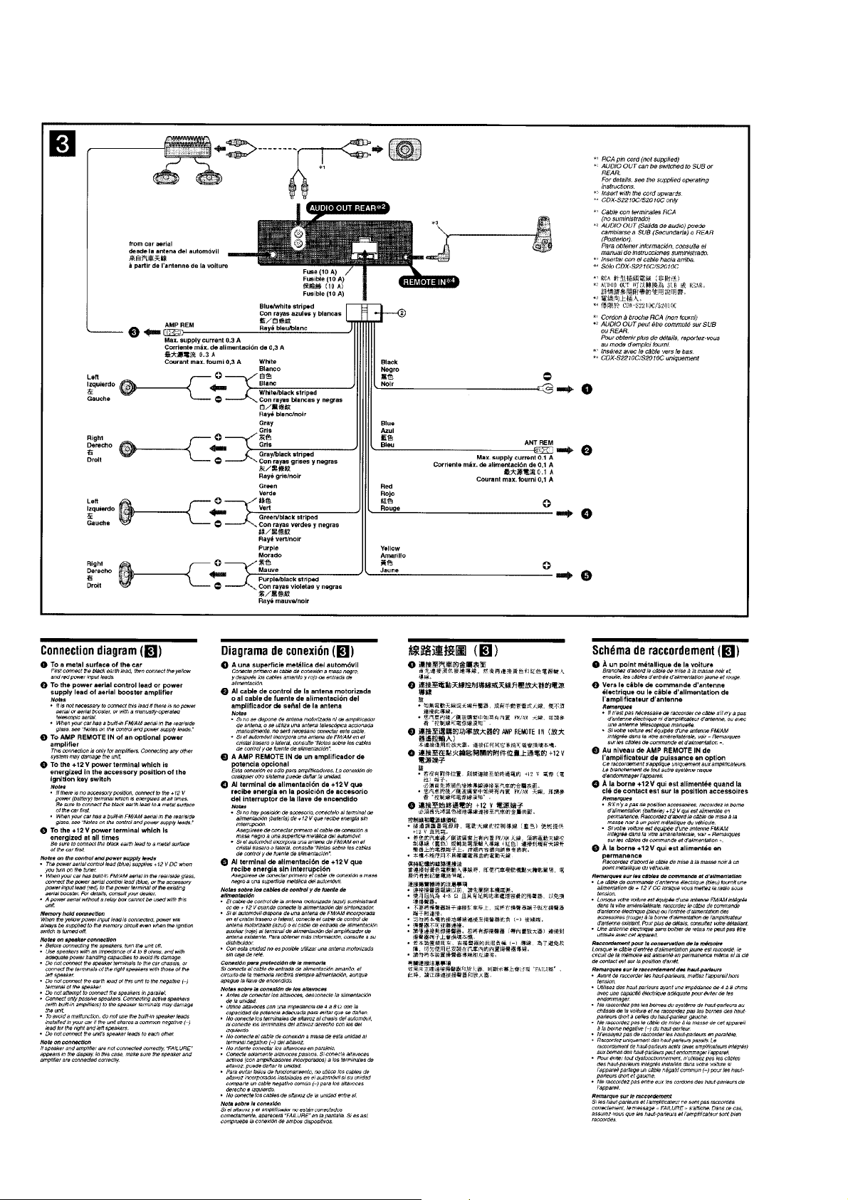
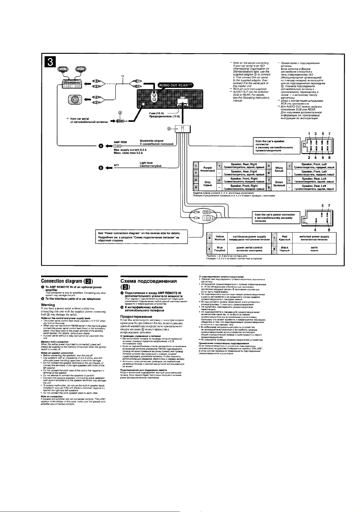
Connections (CDX-SW330)
from car antenna
à partir de l’antenne de la voiture
desde la antena del automóvil
Blue/white striped
AMP REM
3
Max. supply current 0.3 A
Courant max. fourni 0,3 A
Corriente máx. de alimentación de 0,3 A
Rayé bleu/blanc
Con rayas azules y blancas
AUDIO OUT REAR
L
L
R
R
AUDIO
BUS
OUT
AUDIO
IN
Fuse (10 A)
Fusible (10 A)
Fusible (10 A)
1
*
2
*
RCA pin cord (not supplied)
*1
2
*
AUDIO OUT can be switched to SUB or
REAR.
For details, see the supplied operating
instructions.
1
*
Cordon à broche RCA (non fourni)
2
*
AUDIO OUT peut être commuté sur SUB
ou REAR.
Pour obtenir plus de détails, reportez-vous
au mode d’emploi fourni.
1
*
Cable con terminales RCA
(no suministrado)
2
*
AUDIO OUT (Salida de audio) puede
cambiarse a SUB (Secundaria) o REAR
(Posterior).
Para obtener información, consulte el
manual de instrucciones suministrado.
2
Left
Gauche
Izquierdo
Right
Droit
Derecho
Left
Gauche
Izquierdo
Right
Droit
Derecho
Connection diagram (3)
1 To a metal surface of the car
First connect the black ground lead, then connect the yellow
and red power input leads.
2 To the power antenna control lead or power
supply lead of antenna booster amplifi er
Notes
• It is not necessary to connect this lead if there is no power
antenna or antenna booster, or with a manually-operated
telescopic antenna.
• When your car has a built-in FM/AM antenna in the rear/
side glass, see “Notes on the control and power supply
leads.”
3 To AMP REMOTE IN of an optional power
amplifi er
This connection is only for amplifi ers. Connecting any other
system may damage the unit.
4 To the +12 V power terminal which is
energized in the accessory position of the
ignition key switch
Notes
• If there is no accessory position, connect to the +12 V
power (battery) terminal which is energized at all times.
Be sure to connect the black ground lead to a metal
surface of the car fi rst.
• When your car has a built-in FM/AM antenna in the rear/
side glass, see “Notes on the control and power supply
leads.”
5 To the +12 V power terminal which is
energized at all times
Be sure to connect the black ground lead to a metal surface
of the car fi rst.
Notes on the control and power supply leads
• The power antenna control lead (blue) supplies +12 V DC
when you turn on the tuner.
• When your car has built-in FM/AM antenna in the rear/side
glass, connect the power antenna control lead (blue) or the
accessory power input lead (red) to the power terminal of the
existing antenna booster. For details, consult your dealer.
• A power antenna without a relay box cannot be used with this
unit.
Memory hold connection
When the yellow power input lead is connected, power will
always be supplied to the memory circuit even when the ignition
switch is turned off.
Notes on speaker connection
• Before connecting the speakers, turn the unit off.
• Use speakers with an impedance of 4 to 8 ohms, and with
adequate power handling capacities to avoid its damage.
• Do not connect the speaker terminals to the car chassis, or
connect the terminals of the right speakers with those of the
left speaker.
• Do not connect the ground lead of this unit to the negative (–)
terminal of the speaker.
• Do not attempt to connect the speakers in parallel.
• Connect only passive speakers. Connecting active speakers
(with built-in amplifi ers) to the speaker terminals may damage
the unit.
• To avoid a malfunction, do not use the built-in speaker leads
installed in your car if the unit shares a common negative (–)
lead for the right and left speakers.
• Do not connect the unit’s speaker leads to each other.
Note on connection
If speaker and amplifi er are not connected correctly, “FAILURE”
appears in the display. In this case, make sure the speaker and
amplifi er are connected correctly.
White
Blanc
Blanco
White/black striped
é blanc/noir
Ray
Con rayas blancas y negras
Gray
Gris
Gris
Gray/black striped
Rayé gris/noir
Con rayas grises y negras
Green
Ve rt
Ve rd e
Green/black striped
Rayé vert/noir
Con rayas verdes y negras
Purple
Mauve
Morado
Purple/black striped
Rayé mauve/noir
Con rayas moradas y negras
Schéma de raccordement (3)
1 À un point métallique de la voiture
Branchez d’abord le câble de mise à la masse noir et,
ensuite, les câbles d’entrée d’alimentation jaune et rouge.
2 Vers le câble de commande d’antenne
électrique ou le câble d’alimentation de
l’amplifi cateur d’antenne
Remarques
• Il n’est pas nécessaire de raccorder ce câble s’il n'y a pas
d’antenne électrique ni d’amplifi cateur d’antenne, ou avec
une antenne télescopique manuelle.
• Si votre voiture est équipée d’une antenne FM/AM
intégrée dans la vitre arrière/latérale, voir « Remarques
sur les câbles de commande et d’alimentation ».
3 Au niveau de AMP REMOTE IN de
l’amplifi cateur de puissance en option
Ce raccordement s’applique uniquement aux amplifi cateurs.
Le branchement de tout autre système risque
d’endommager l’appareil.
4 À la borne +12 V qui est alimentée quand la
clé de contact est sur la position accessoires
Remarques
• S’il n’y a pas de position accessoires, raccordez la borne
d’alimentation (batterie) +12 V qui est alimentée en
permanence. Raccordez d’abord le câble de mise à la
masse noir à un point métallique du véhicule.
• Si votre voiture est équipée d’une antenne FM/AM
intégrée dans la vitre arrière/latérale, voir « Remarques
sur les câbles de commande et d’alimentation ».
5 À la borne +12 V qui est alimentée en
permanence
Raccordez d’abord le câble de mise à la masse noir à un
point métallique du véhicule.
Remarques sur les câbles de commande et d’alimentation
• Le câble de commande d’antenne électrique (bleu) fournit une
alimentation de + 12 V CC lorsque vous mettez la radio sous
tension.
• Lorsque votre voiture est équipée d’une antenne FM/AM intégrée
dans la vitre arrière/latérale, raccordez le câble de commande
d’antenne (bleu) ou l’entrée d’alimentation des accessoires
(rouge) à la borne d’alimentation de l’amplifi cateur d’antenne
existant. Pour plus de détails, consultez votre détaillant.
• Une antenne électrique sans boîtier de relais ne peut pas être
utilisée avec cet appareil.
Raccordement pour la conservation de la mémoire
Lorsque le câble d’entrée d’alimentation jaune est raccordé, le
circuit de la mémoire est alimenté en permanence même si la clé
de contact est sur la position d’arrêt.
Remarques sur le raccordement des haut-parleurs
• Avant de raccorder les haut-parleurs, mettez l’appareil hors
tension.
• Utilisez des haut-parleurs ayant une impédance de 4 à 8 ohms
avec une capacité électrique adéquate pour éviter de les
endommager.
• Ne raccordez pas les bornes du système de haut-parleurs au
châssis de la voiture et ne raccordez pas les bornes des hautparleurs droit à celles du haut-parleur gauche.
• Ne raccordez pas le câble de mise à la masse de cet appareil
à la borne négative (–) du haut-parleur.
• N’essayez pas de raccorder les haut-parleurs en parallèle.
• Raccordez uniquement des haut-parleurs passifs. Le
raccordement de haut-parleurs actifs (avec amplifi cateurs intégrés)
aux bornes des haut-parleurs peut endommager l’appareil.
• Pour éviter tout dysfonctionnement, n’utilisez pas les câbles
des haut-parleurs intégrés installés dans votre voiture si
l’appareil partage un câble négatif commun (–) pour les hautparleurs droit et gauche.
• Ne raccordez pas entre eux les cordons des haut-parleurs de
l’appareil.
Remarque sur le raccordement
Si les haut-parleurs et l’amplifi cateur ne sont pas raccordés
correctement, le message « FAILURE » s’affi che. Dans ce cas,
assurez-vous que les haut-parleurs et l’amplifi cateur sont bien
raccordés.
Black
Noir
Negro
Blue
Bleu
Azul
Red
Rouge
Rojo
Yellow
Jaune
Amarillo
Corriente máx. de alimentación de 0,1 A
Max. supply current 0.1 A
Courant max. fourni 0,1 A
Diagrama de conexión (3)
1 A una superfi cie metálica del automóvil
Conecte primero el cable de conexión a masa negro, y
después los cables con rayas naranjas y blancas, amarillo, y
rojo de entrada de alimentación.
2 Al cable de control de la antena motorizada
o al cable de fuente de alimentación del
amplifi cador de señal de la antena
Notas
• Si no se dispone de antena motorizada ni de amplifi cador
de antena, o se utiliza una antena telescópica accionada
manualmente, no será necesario conectar este cable.
• Si el automóvil incorpora una antena de FM/AM en el
cristal trasero o lateral, consulte “Notas sobre los cables
de control y de fuente de alimentación”.
3 A AMP REMOTE IN de un amplifi cador de
potencia opcional
Esta conexión es sólo para amplifi cadores. La conexión de
cualquier otro sistema puede dañar la unidad.
4 Al terminal de alimentación de +12 V que
recibe energía en la posición de accesorio
del interruptor de la llave de encendido
Notas
• Si no hay posición de accesorio, conéctelo al terminal de
alimentación (batería) de +12 V que recibe energía sin
interrupción.
Asegúrese de conectar primero el cable de conexión a
masa negro a una superfi cie metálica del automóvil.
• Si el automóvil incorpora una antena de FM/AM en el
cristal trasero o lateral, consulte “Notas sobre los cables
de control y de fuente de alimentación”.
5 Al terminal de alimentación de +12 V que
recibe energía sin interrupción
Asegúrese de conectar primero el cable de conexión a masa
negro a una superfi cie metálica del automóvil.
Notas sobre los cables de control y de fuente de
alimentación
• El cable de control de la antena motorizada (azul) suministrará
cc de + 12 V cuando conecte la alimentación del sintonizador.
• Si el automóvil dispone de una antena de FM/AM incorporada
en el cristal trasero o lateral, conecte el cable de control de
antena motorizada (azul) o el cable de entrada de alimentación
auxiliar (rojo) al terminal de alimentación del amplifi cador de
antena existente. Para obtener más información, consulte a su
distribuidor.
• Con esta unidad no es posible utilizar una antena motorizada
sin caja de relé.
Conexión para protección de la memoria
Si conecta el cable de entrada de alimentación amarillo, el
circuito de la memoria recibirá siempre alimentación, aunque
apague la llave de encendido.
Notas sobre la conexión de los altavoces
• Antes de conectar los altavoces, desconecte la alimentación
de la unidad.
• Utilice altavoces con una impedancia de 4 a 8
capacidad de potencia adecuada para evitar que se dañen.
• No conecte los terminales de altavoz al chasis del automóvil,
ni conecte los terminales del altavoz derecho con los del
izquierdo.
• No conecte el cable de conexión a masa de esta unidad al
terminal negativo (–) del altavoz.
• No intente conectar los altavoces en paralelo.
• Conecte solamente altavoces pasivos. Si conecta altavoces
activos (con amplifi cadores incorporados) a los terminales de
altavoz, puede dañar la unidad.
• Para evitar fallos de funcionamiento, no utilice los cables de
altavoz incorporados instalados en el automóvil si su unidad
comparte un cable negativo común (–) para los altavoces
derecho e izquierdo.
• No conecte los cables de altavoz de la unidad entre sí.
Nota sobre la conexión
Si el altavoz y el amplifi cador no están conectados
correctamente, aparecerá “FAILURE” en la pantalla. Si es así,
compruebe la conexión de ambos dispositivos.
Ω
con la
ANT REM
1
2
4
5
10
SECTION 2
s
DISASSEMBLY
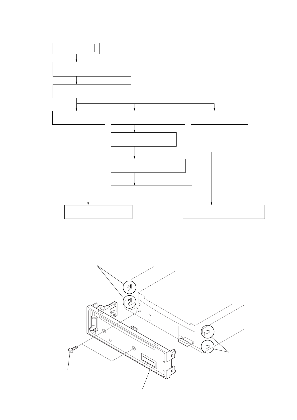
Note : This set can be disassemble according to the following sequence.
SET
2-1. SUB PANEL (LCD) ASSY
(Page 11)
2-2. CD MECHANISM BLOCK
(Page 12)
CDX-S2210/S2210S/S2210X/S2250EE/SW330
2-3. MAIN BOARD
(Page 12)
2-4. CHASSIS (T) SUB ASSY
(Page 13)
2-5. ROLLER ARM ASSY
(Page 13)
2-6. CHASSIS (OP) ASSY
(Page 14)
2-8. SL MOTOR ASSY (M902)
(Page 15)
2-7. OPTICAL PICK-UP
(Page 14)
Note : Follow the disassembly procedure in the numerical order given.
2-1. SUB PANEL (LCD) ASSY
2-10. SERVO BOARD
(Page 16)
2-9. LE MOTOR ASSY (M903)
(Page 15)
1
two
screws
(+PTT 2.6
x
6)
3
two claws
4
sub panel (LCD) assy
2
two claw
11
CDX-S2210/S2210S/S2210X/S2250EE/SW330
)
)
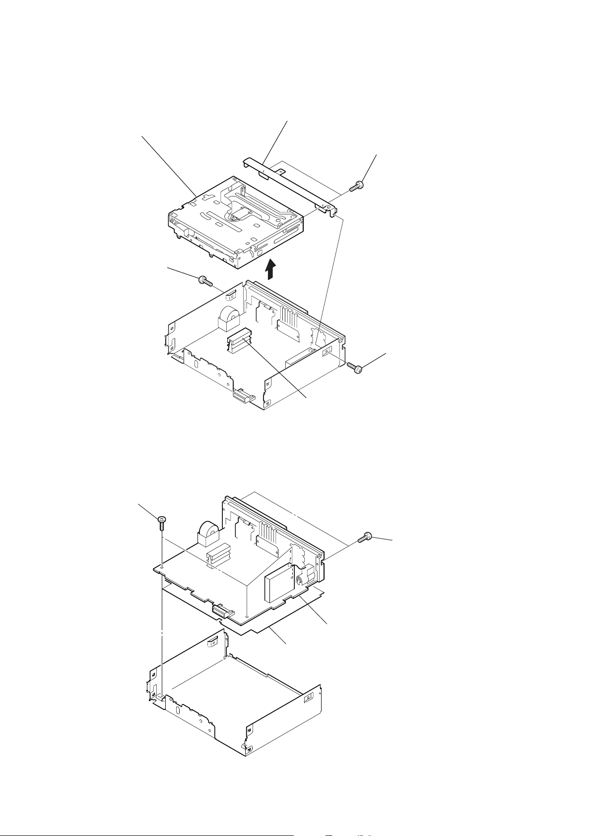
2-2. CD MECHANISM BLOCK
5
CD mechanism block
2
screw
(+PTT 2.6
x
6)
7
bracket (CD)
3
6
two
screws
(+PTT 2.6
x
4)
2-3. MAIN BOARD
1
(+BTT)
three screws
4
CNP301
3
MAIN board
1
screw
(+PTT 2.6
2
two
screws
(+PTT 2.6
x
x
6
8
12
4
insulating sheet
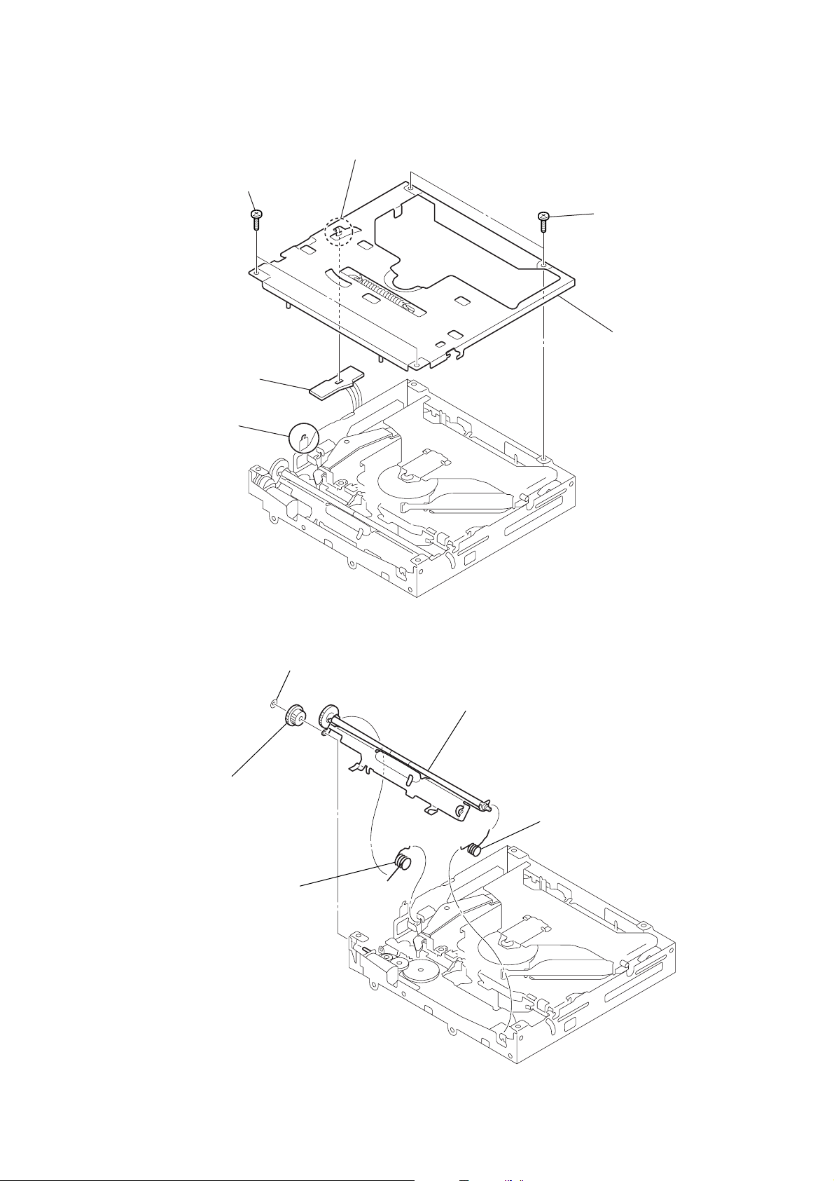
2-4. CHASSIS (T) SUB ASSY
2
two
screws
x
(+P 1.7
5
SENSOR board
3
claw
2.2)
4
claw
CDX-S2210/S2210S/S2210X/S2250EE/SW330
1
two
screws
x
(+P 1.7
6
2.2)
chassis (T) sub assy
2-5. ROLLER ARM ASSY
4
gear (RA1)
1
spring (RAL)
3
washer (1.1-2.5)
5
roller arm assy
2
spring (RAR)
13
CDX-S2210/S2210S/S2210X/S2250EE/SW330
)
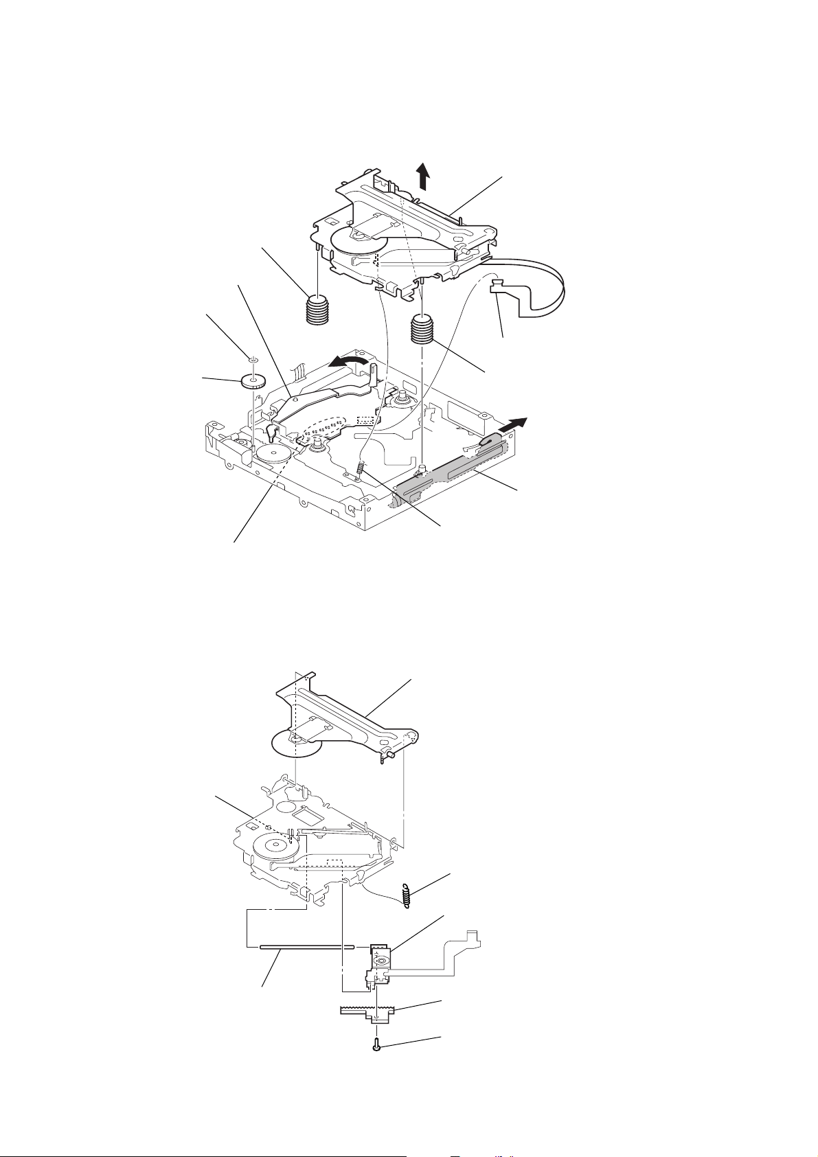
2-6. CHASSIS (OP) ASSY
0
coil spring (damper)
lever (D)
4
washer
6
5
gear (LE1)
8
qa
chassis (OP) assy
1
CN2 (16P)
9
two coil springs (damper)
7
2-7. OPTICAL PICK-UP
5
claw
2
Remove the six solderings.
3
tension coil spring (KF60)
2
chucking arm sub assy
1
tension coil spring (CHKG
slider (R)
14
6
main shaft
7
optical pick-up
4
rack (SL)
3
screw
(+B 1.4
x
5)
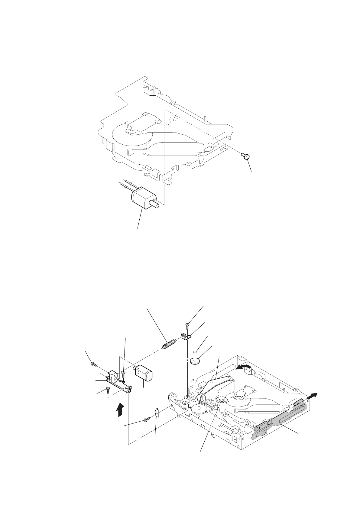
2-8. SL MOTOR ASSY (M902)
CDX-S2210/S2210S/S2210X/S2250EE/SW330
1
screw
(+P 1.4
x
1.8)
2-9. LE MOTOR ASSY (M903)
qf
two toothed lock
(+M 1.4
bracket (LEM-N)
qs
(+M 1.7
screw
x
)
2.5)
screws
qd
2
SL motor assy (M902)
qa
screw
(+M 1.7
qg
(M903)
0
gear (LE) assy
x
2.5)
LE motor assy
8
screw
(+M 1.7
9
2
x
bearing (LEB-N)
washer
3
gear (LE1)
lever (D)
2.5)
4
5
6
screw
(+P 1.7
x
2.2)
7
leaf spring (LE)
1
Remove the soldering.
slider (R)
15
CDX-S2210/S2210S/S2210X/S2250EE/SW330
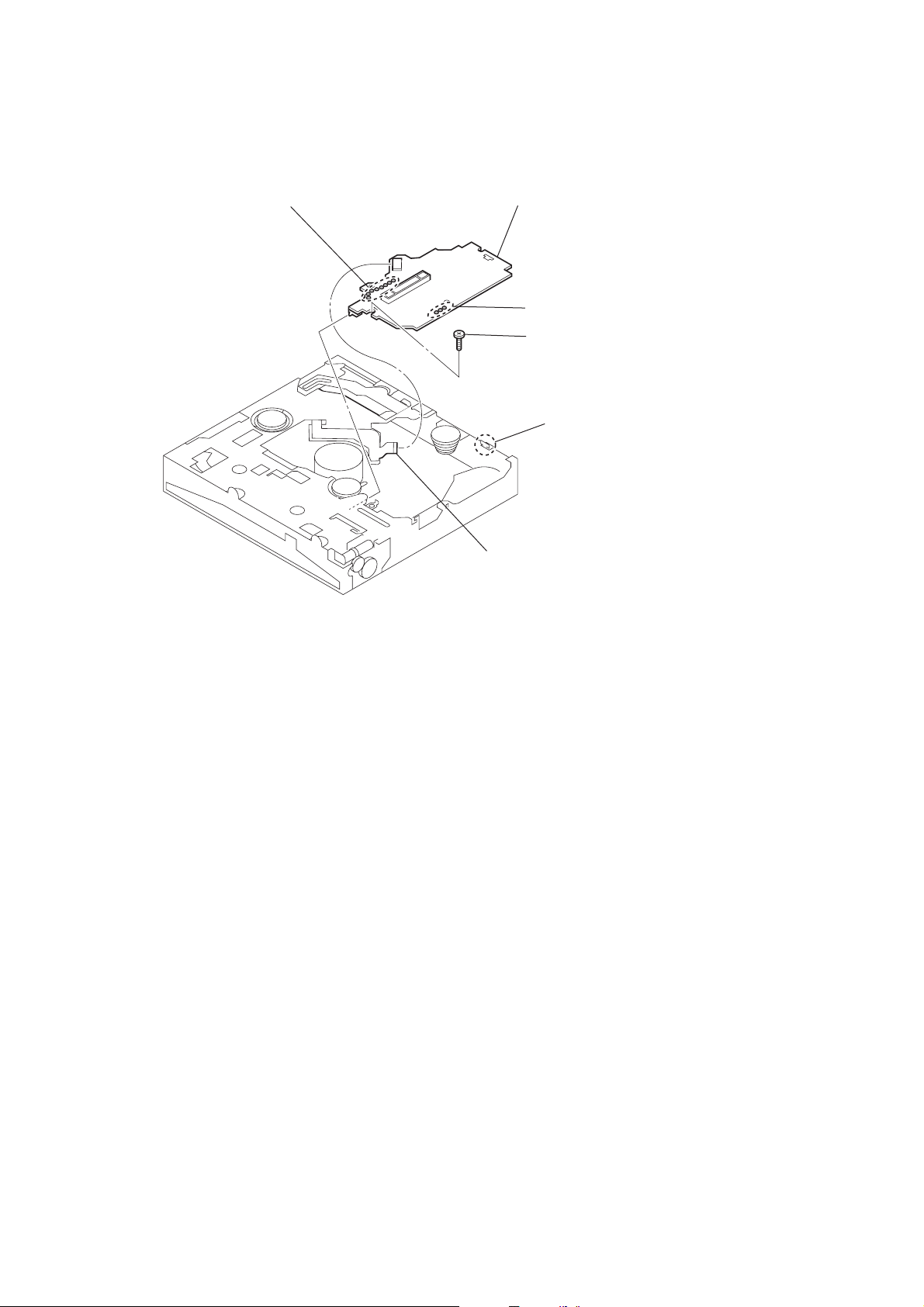
2-10. SERVO BOARD
1
Remove the eight solderings.
6
SERVO board
2
Remove the three solderings.
4
toothed lock
(M 1.7)
5
claw
screw
3
CN2 (16P)
16
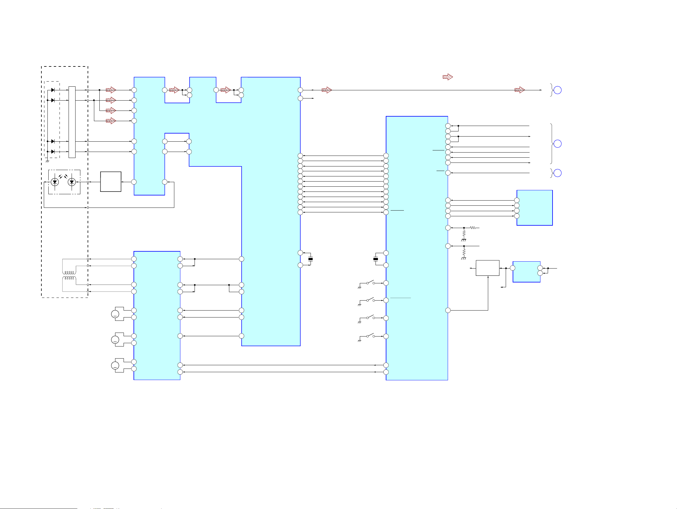
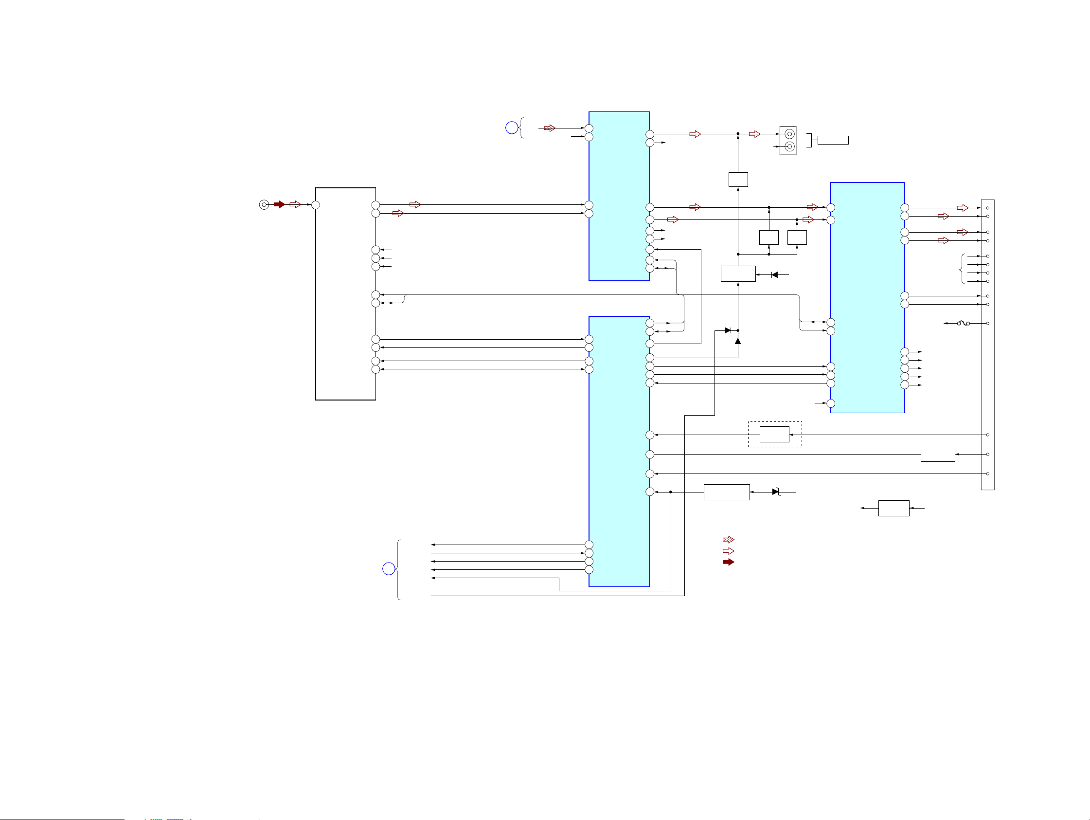
3-1. BLOCK DIAGRAM – CD SECTION –
DETECTOR
PD1
PD2
E
F
LASER DIODE
PICK-UP BLOCK
(KSS1000E)
2-AXIS DEVICE
(FOCUS)
(TRACKING)
PD LD
OPTICAL
PD2
PD1
I-V AMP
MON OUT
FCS+
FCS–
TRK+
TRK–
FPI2
96
FNI2
94
FPI1
97
FNI1
95
E
F
LD
AUTOMATIC
POWER
CONTROL
M902
(SLED)
Q1
M
99
TNI
98
TPI
91
LDO
FOCUS/TRACKING COIL DRIVE,
SLED/SPINDLE/LOADING
MOTOR DRIVE
16
VO4–
15
VO4+
18
VO3–
17
VO3+
14
VO1+
13
VO1–
RFEQO
RFRP
MDI
IC1
SECTION 3
DIAGRAMS
79
3
TEI
6
92
OPIN4–
26
OPOUT4
25
OPIN3–
23
OPOUT3
22
OPOUT1
4
OPIN2
7
CDX-S2210/S2210S/S2210X/S2250EE/SW330
• R-ch is omitted due to same as L-ch.
• Signal Path
: CD PLAY
RFO
RFI
77
RFRPI
78
RFZI
1
TEZI
7
87
RF AMP,DIGITAL SERVO,
DIGITAL SIGNAL PROCESSOR
IC2
85
86
9
10
46
12
13
AGCI
RFDCI
F0O
TRO
IO0(/HSO)
FMO
DMO
MUTE
REQ
STBY
ZDET
/RST
/CCE
BUCK
BUS3
BUS2
BUS1
BUS0
SBSY
UNI SI
UNI SO
UNI CLK
BUS ON
B/U CHECK
ATT
SYS RST
IC501 (1/3)
VDD
CE
CD-L
15
3
30
LO
27
RO
XI
XO
R-CH
UNISI
56
RXD
25
UNISO
57
TXD
26
UNICKI
58
BUS ON
DEC XMUTE
56
53
43
18
42
41
40
39
38
37
36
14
23
24
X2
16.934MHz
SW1
(DOWN)
SW2
(SELF)
SW3
(DISC IN)
X1
12MHz
37
DEC INT
30
DEC SSTBY
27
CD ZDET
15
CD XRST
14
CD XCCE
13
CD BUCK
12
CD BUS3
11
CD BUS2
10
CD BUS1
8
CD BUS0
7
CD SBSY
52
X1
81
X0
80
MEC_DSW
46
MEC_SELFSW
53
MEC_INSW
45
CD
SYSTEM CONTROL
IC3
MECON CHK
BU IN
A ATT
RSTX
EJECT OK
MECON
CDON
ZMUTE
CDON CHK
1.5V ON
50
51
60
75
SYSTEM CONTROL
61
63
64
66
67
68
+1.5V
1
MECHA+6V
BU+3.3V
+1.5V ON/OFF
SWITCH
Q2,3
+1.5V
EJECT OK SW
89
CDM ON
99
CD ON
98
Z MUTE
93
+1.5V REG
VOUT
IC6
A
SECTION
(Page 18)
B
SECTION
(Page 18)
DISPLAY
C
SECTION
(Page 19)
BU+3.3V
MAIN
MAIN
12
M901
(SPINDLE)
M903
(LOADING)
M
M
VO2+
11
VO2–
10
VOL+
9
VOL–
CDX-S2210/S2210S/S2210X/S2250EE/SW330
MUTE
FWD
REV
IO1(/UHSO)
21
1
28
47
SW4
(LIMIT)
42
43
44
MEC_LIMIT
MEC LOAD
MEC EJECT
17 17
CDX-S2210/S2210S/S2210X/S2250EE/SW330
3-2. BLOCK DIAGRAM – MAIN SECTION –
ELECTRONIC VOLUME
IC401
J1
(ANTENNA)
1
ANT
TU1
(TUNER UNIT)
TU VDD
E2P VDD
TU-SCL
TU-SDA
S-METER
TU MUTE
E2P SCL
E2P SDA
L-CH
4
R-CH
3
10
VCC
11
15
13
14
6
7
16
17
CD
SECTION
(Page 17)
AUDIO+8.3V
TU+5V
BU+3.3V
SCL
SDA
B
UNI SI
UNI SO
UNI CLK
BUS ON
B/U CHECK
ATT
CD
SECTION
(Page 17)
CD-L
A
R-CH
9
CD LCH
8
CD RCH
7
TU LCH
6
TU RCH
SYSTEM CONTROL
IC501 (2/3)
39
VSM
12
TU ATT
25
EEP CKO
24
EEP SIO
58
UNI SI
59
UNI SO
60
UNI SCK
87
BUS ON
OUT SUB-L
OUT SUB-R
OUT FL
OUT RL
OUT FR
OUT RR
MUTE
SCL
SDA
I2C CKO
I2C SIO
VOL ATT
ATT
BEEP
AMP STB
DIAG
TEL ATT
ACC IN
TEST IN
BU IN
17
18
23
22
25
24
29
30
31
33
34
9
86
5
26
8
74
72
73
54
R-CH
R-CH (FRONT)
R-CH (REAR)
SCL
SDA
SCL
SDA
R-CH
MUTE
Q481
MUTE
Q441
D571
S2250EE
D479
TEL MUTE
Q651
D580,581
MUTE DRIVE
Q478,479
BATTERY CHECK
Q580-582
• R-CH is omitted due to same as L-CH.
• Signal Path
: CD PLAY
: FM
: MW/LW
MUTE
Q461
BATT
L
R
SDA
SCL
BATT
BATT
J330
AUDIO OUT
12
IN FL
11
IN RL
2
SDA
4
SCL
16
BEEP
22
STB
25
DIAG
35
VP
POWER AMP,
POWER SUPPLY
IC750
TU+5V
OUT FL+
OUT FL-
OUT RL+
OUT RL-
AMP-REM
ANT-REM
AUDIO8.3V
B.UP+B
SERVO3.3V
MECHA6V
PANEL+B
+5V REG
Q1
29
27
30
37
31
33
34
5
3
9
7
R-CH
BATT
AUDIO+8.3V
BU+3.3V
SERVO+3.3V
MECHA+6V
PANEL+B
ACC CHECK
Q631
AUDIO+8.3V
FU601
CN601
10
12
11
16
13
15
1
FL+
9
FL-
2
RL+
RL-
4
FR+
FR-
3
RR+
RR-
5
AMP-REM
6
ANT-REM
TEL-MUTE
7
ACC
TEST
CDX-S2210/S2210S/S2210X/S2250EE/SW330
1818
CDX-S2210/S2210S/S2210X/S2250EE/SW330
t
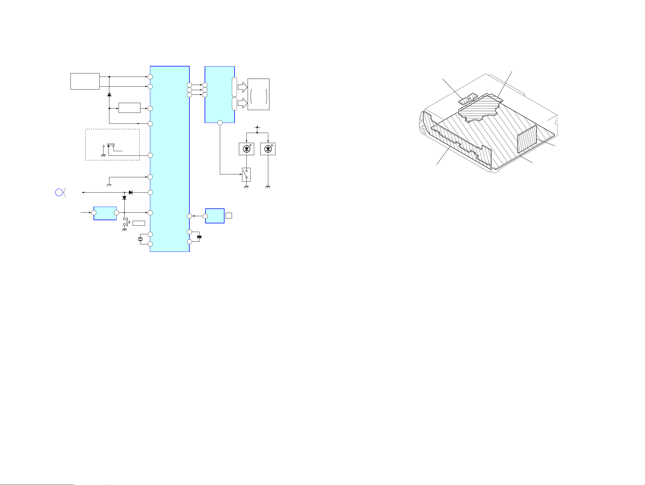
3-3. BLOCK DIAGRAM – DISPLAY SECTION –
SYSTEM CONTROL
41
40
52
76
3
7
88
77
79
80
KEYIN0
KEYIN1
KEY ACK
XKEY ON
AREA SEL0
NOSE DET
SYS RST
RESET
XOUT
XIN
CD
SECTION
(Page 17)
KEY MATRIX
LSW901-911,
913-921
D503
KEY ACK ON
Q664
S2210S,S2210X
S502
(FREQUENCY SELECT)
9k T 10k
BU+3.3.V
SYS RST
C
RESET
IC602
2 1
BU+3.3V
VDD VOUT
D510
X502
32.678kHz
S702
RESET
IC501 (3/3)
LCD CKO
OSC OUT
LCD SO
LCD CE
SIRCS
OSC IN
• Circuit Boards Location
LCD DRIVER
IC901
4
S1
28
64
DI
CL
29
27
64
82
83
CLK
63
CE
CE
62
IR RECEIVER
IC971
OUT
2
X501
18.432MHz
|
|
50
•
S48
55
COM4
51
|
|
COM1
54
DIMMER
1
LED931,932
LCD BACK
()
LIGHT
IR
LCD901
LIQUID
CRYSTAL
DISPLAY
PANEL
PANEL+B
Q921
LED
CONTROL
LED951,952
LSW901-911,
913-921
SENSOR board
KEY board
SERVO board
tuner uni
(TU1)
MAIN board
CDX-S2210/S2210S/S2210X/S2250EE/SW330
19 19
CDX-S2210/S2210S/S2210X/S2250EE/SW330
Ver. 1.3
• NOTE FOR PRINTED WIRING BOARDS AND SCHEMATIC DIAGRAMS
THIS NOTE IS COMMON FOR PRINTED WIRING
BOARDS AND SCHEMATIC DIAGRAMS.
(In addition to this, the necessary note is printed
in each block.)
For schematic diagrams.
Note:
• All capacitors are in µF unless otherwise noted. pF: µµF
50 WV or less are not indicated except for electrolytics
and tantalums.
• All resistors are in Ω and 1/
specified.
f
•
• C : panel designation.
• A : B+ Line.
• B : B– Line.
• H : adjustment for repair.
•Voltages and waveforms are dc with respect to ground
• CD mechanism section (1/2), (2/2)
no mark : CD PLAY
• Main (1/4), (2/4), (3/4), (4/4) and Display sections
no mark : FM
: internal component.
Note:
The components identified by mark 0 or dotted
line with mark 0 are criti-
cal for safety.
Replace only with part
number specified.
under no-signal (detuned) conditions.
(): AM
<>: CD PLAY
4
W or less unless otherwise
Note:
Les composants identifiés par
une marque 0 sont critiques
pour la sécurité.
Ne les remplacer que par une
piéce portant le numéro
spécifié.
For printed wiring boards.
Note:
• X : parts extracted from the component side.
• Y : parts extracted from the conductor side.
a
•
• : Pattern from the side which enables seeing.
(The other layers' patterns are not indicated.)
Caution:
Pattern face side: Parts on the pattern face side seen from the
(Side B) pattern face are indicated.
Parts face side: Parts on the parts face side seen from the
(Side A) parts face are indicated.
: Through hole.
C
Q
These are omitted
EB
E
CB
These are omitted
∗ : Impossible to measure
•Voltages are taken with a VOM (Input impedance 10 M Ω).
Voltage variations may be noted due to normal production tolerances.
•Waveforms are taken with a oscilloscope.
Voltage variations may be noted due to normal production tolerances.
• Circled numbers refer to waveforms.
• Signal path.
J : CD PLAY
F : FM
f : AM
C
BE
These are omitted
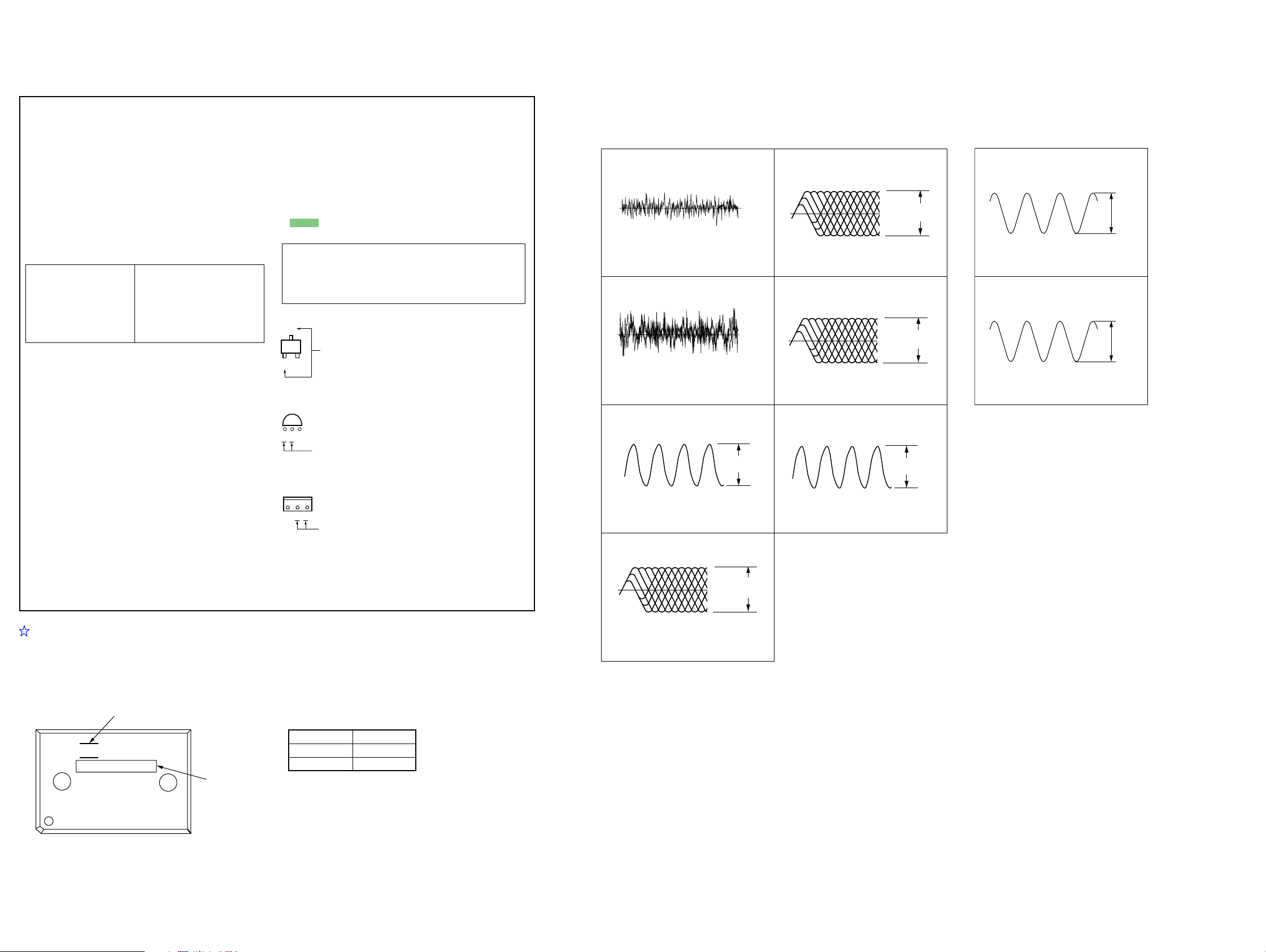
• Waveforms
— SERVO Board —
(CD PLAY) — MAIN Board —
1
1
IC2 4 (FEI)
Approx. 100 mVp-p
50 mV/DIV, 5 msec/DIV
2
IC2 6 (TEI)
Approx. 400 mVp-p
200 mV/DIV, 5 msec/DIV
3
IC2 wd (XI)
16.9344 MHz
0.2 V/DIV, 0.2 µsec/DIV
4
IC2 uj (RFI)
0 V
0 V
0.6 Vp-p
Approx.
1Vp-p
5
IC2 of (FNI2),
0.5 V/DIV, 0.5 µsec/DIV
6
IC2 oh (FPI2),
0.5 V/DIV, 0.5 µsec/DIV
7
IC3 ia (X1)
12 MHz
0.5 V/DIV, 0.2 µsec/DIV
og (FNI1)
1.5 Vp-p
oj (FPI1)
1.5 Vp-p
1.1 Vp-p
IC501 i; (XIN)
32.678kHz
2
IC501 id (OSCOUT)
18.432MHz
1.4Vp-p
1.2Vp-p
NOTE FOR REPLACEMENT OF THE IC501
IC501 on the main board has two types of IC models: MB90487 and MB90F488B.
The service part is the model MB90487 only.
Check the model number printed on the IC when replacing IC501.
If MB90F488 is printed on the IC, mount the capacitor C551 additionally.
company emblem
IC501 C351
F
JAPA N
MB90487A 0.001µF
MB90F488B NO MOUNT
MB90487A
MB90F488B
CDX-S2210/S2210S/S2210X/S2250EE/SW330
0.5 V/DIV, 0.5 µsec/DIV
2020
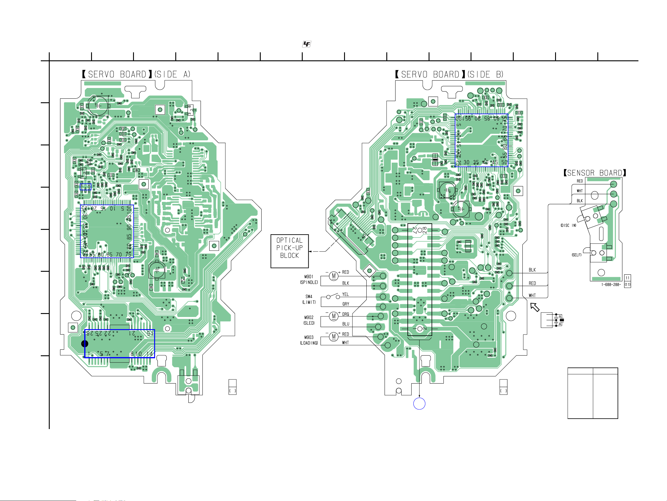
3-4. PRINTED WIRING BOARDS – SERVO BOARD – • See page 19 for Circuit Boards Location. : Uses unleaded solder.
CDX-S2210/S2210S/S2210X/S2250EE/SW330
A
B
C
D
E
F
G
H
1
R21
FMA3
C22
C102
C72
C80
C29
R84
C32
C65
C20
R86
R73
R13
IC6
R10
C35
Q3
Q2
C106
C64
234567891011 12 13 14
TP27
TP26
TP29
TP39
R71
R8
C9
C19
C67
R68
R122
R70
TP40
C51
C62
R69
R11
C57
R66
R56
IC3
R65
TP53
R9
C41
R58
R57
R16
R132
C39
R47
TP51
R101
C48
R54
IC1
C38
C40
R17
R40
R48
R42
R25
R50
R100
C45
R123
R12
TP30
R41
FB4
C43
TP48
TP37
TP38
C101
TP49
R43
C6
R26
FMA4
C103
C37
FB2
R120
C61
FMA6
FB3
C27
TP78
TP79
TP80
C34
R45
R51
C58
R28
R49
C60
TP44
TP23
TP93
R128
R64
X1
TP82
TP31
FMB3
TP22
TP14
R6
R7
TP18
R131
R113
(DOWN)
C7
SW1
R112
Q1
TP17
C10
R4
TP13
FMA5
TP24
TP12
CN1
(KSS1000E)
TP16
C4
R1
TP88
C5
TP92
FMB5
TP2
TP1
TP9
TP8
TP11
R5
TP20
TP89
TP90
TP91
TP10
TP6
TP7
TP97
TP99
TP21
TP15
TP68
TP36
C33
CN2
TP42
TP35
TP95
X2
TP34
TP41
TP81
TP33
C42
R46
C59
TP43
TP74
TP77
TP83
TP85
11
1-864-900-
11
C16
C49
R127
R125
R63
R117
TP101
R67
TP76
R55
R53
TP98
TP84
TP86
1-864-900-
IC2
R62
TP87
C23
R126
R60
TP66
TP75
TP32
C17
C13
R61
R91
R82
R2
R78
R59
R118
TP62
R83
R81
C18
R121
R116
R74
C21
R72
TP65
C52
R3
C53
R119
R77
11
11
TP25
C24
C31
R22
TP47
R52
R90
C105
R23
R24
TP3
TP4
TP5
R19
C36
TP46
C47
TP64
TP67
C28
TP63
R44
FMB4
R80
SW3
SW2
X1
• Semiconductor
Location
Ref. No. Location
IC1 G-2
IC2 B-11
IC3 E-2
IC6 D-1
CDX-S2210/S2210S/S2210X/S2250EE/SW330
21 21
A
MAIN BOARD CNP301
(Page 24)
Q1 B-4
Q2 C-1
Q3 C-1
CDX-S2210/S2210S/S2210X/S2250EE/SW330
3-5. SCHEMATIC DIAGRAM – SERVO BOARD (1/2) – • See page 32 for IC Block Diagram. • See page 20 for Waveforms.
CN1
TP12
TP13
TP14
TP15
TP16
TP17
TP18
TP20
C35
C32
C29
R21
R19
C28
C24
TP25
C21
C13
C4
R1
R4
C18
C17
C19
C20
C10
R13
C22
TP93
C16
TP26
TP27
C23
TP29
TP30
C31
R22
R23
R24
C36
R44
TP46
TP47
IC2
C47
C102
C52
C53
R52
R72
R71
R125
R126
R127
R128 R64
C49
C58
R51
C60
C51
C57
C62
R59
R60
R61
R62
R63
C48
R49
C59
R113
TP101
R131
Q2 R86
Q3
C67
R84
C72
IC B/D
IC6
C80
IC B/D
C101
C45
R123
R46R45
X2
FB4
FB3
C5
C27
R5
TP33
TP34
TP35
TP36
C33
R25
R26
TP41
TP42
R40
C42
R41
CDX-S2210/S2210S/S2210X/S2250EE/SW330
R132
C7
Q1
TP21 TP22
R7
C9
R6
C34
C38
TP37
C39
TP38
C40
TP39
C41
TP40
C61
FB2
R112
(Page 23)
2222
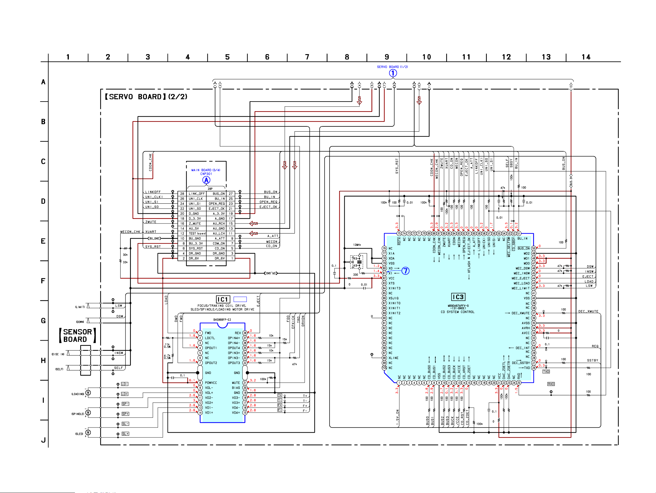
3-6. SCHEMATIC DIAGRAM – SERVO BOARD (2/2) – • See page 31 for IC Block Diagram. • See page 20 for Waveforms. • See page 35 for IC Pin Descriptions.
(Page 22)
CDX-S2210/S2210S/S2210X/S2250EE/SW330
SW3
SW2
SW4
M903
M901
M902
SW1
TP1
TP2
TP3
TP4
TP5
TP10
TP11
TP7
TP6
TP9
TP8
R100
R101
TP74
TP75
TP76
TP77
TP78
TP79
TP80
TP81
TP82
TP83
TP84
TP85
TP86
TP87
R3
R2
R119
R116
TP62
R74
C65
TP63
C105
TP64
TP65
R121
TP66
TP67
R77
R81
R82
R83
R80
R78
R91
R90
R70
C106
R122
R73
C64
R118
CN2
IC1
C6
IC B/D
TP88
TP89
TP90
TP91
TP92
TP97
TP98
TP99
R12
R10
R8
R11
R9
R16
TP23
TP24
TP31
TP32
R17
C37
R120
R28
R42 R43
TP49
TP48
X1
C103
TP44
TP43
C43
R47
R48
TP51
R50
TP53
R53
R54
R56
R55
R57
R58
R67
R69
R65
IC3
R66
R68
R117
CDX-S2210/S2210S/S2210X/S2250EE/SW330
23 23
CDX-S2210/S2210S/S2210X/S2250EE/SW330
Ver. 1.3
3-7. PRINTED WIRING BOARD – MAIN BOARD – • See page 19 for Circuit Boards Location. : Uses unleaded solder.
1
234567891011 12 13 14
J330
AUDIO OUT
A
J1
B
C
D
E
F
G
H
C484
D702
JW
JW
Q471
JC445
Q481
R471
R481
C471
C481
C401
L1
R501
128
139
CN701
R482
D701
JC12
143
142
JW
JW
JC1
110
JW
C11
TU1
TUNER
UNIT
101
JW
C7
JW
R4
R5
I
104
JW
100
105
JW
R12
R13
C12
C13
R3
C404
C405
R2
R1
C4
C6
R703
138
JW
D1
Q1
94
JW
C5
FB1
78
JW
60
JW
R707
C441
C431
R706
JC446
R443
R431
R453
JC401
IC401
71
JW
R441
JW
JW
JW
JW
JW
R705
Q441
91
129
130
121
122
JW
R570
70
JW
C474
R451
R461
150
JW
JW
R575
R577
C442
R433
C452
C462
R463
C451
R405
C413
R406
R408
R407
R409
R411
80
76
JW
R472
C412
83
JW
C432
54
JW
R442
C461
89
JW
FB603
D719
Q431
JW
JW
R557
108
JW
123
R452
R462
R401
132
JW
81
90
R432
22
JW
R410
C756
Q451
Q461
JW
C753
69
JW
88
133
JW
R513
20
JW
131
JW
R534
R532
103
JW
FB501
R511
C758
R514
C761
74
JW
D503
JW
40
JW
R504
73
JW
R510
92
C755
C503
R512
R502
R503
C763
C754
JC506
67
JW
R505
C776
C751
JW
JW
JW
17
JW
C623
59
JW
93
JW
R752
JW
S2210S,S2210X
S502
FREQUENCY
SELECT
9K
10K
C504
R521
R522
68
JW
14
15
16
JW
C479
Q479
97
C531
R544
C516
C501
JC504
R671
JC754
C750
95
S2210,SW
C513
C771
R545
R546
R550
R756
R565
D755
C769
Q478
D479
18
JW
R551
R507
R537
C512
C514
C502
R567
330
13
JW
JC755
D756
R479
EXCEPT
S2250EE
FMB4
12
JW
C759
66
JW
R549
R538
R573
IC501
IC750
24
JW
D511
C775
C765
D758
FM
11
JW
D757
25
JW
B3
JC501
10
JW
C770
42
JW
R531
S2250EE
R681
R528
R558
R517
JC753
C774
9
JW
C764
JC756
7
JW
D753
C760
C622
FB605
FB604
118
R677
JW
S2210,S2250EE,SW330
S2250EE
X502
JC503
R561
Q664
JW
6
JW
D754
R676
C510
C509
R568
144
8
137
JW
JW
S2250EE
5
JW
D752
D751
C752
23
JW
JC681
29
JW
30
JW
R675
R566
C511
R509
R508
C508
C507
R533
R529
R518
D502
141
JW
L501
140
JW
26
JW
FB302
C406
56
JW
L301
C407
50
JW
R679
R519
R536
D764
D763
98
JW
C310
C309
75
JW
R652
R653
FB304
C302
JC511
X501
JC527
R542
R535
J
(Page 29)
Refer to page 20 for
NOTE FOR REPLACEMENT OF THE IC501
FB307
R301
28
JW
D512
R674
R672
RESET
C308
R302
D510
S702
S702
EXCEPT S2250EE
CN601
FU601
1
32
115
FB310
109
R539
JW127
Q631
C602
R540
R541
JW
2
JW
D601
106
JW
117
JW
R631
R634
R632
R633
C631
D581
Q580
D580
JC581
L601
JW
S2250EE
R583
R582
57
(Page 21)
• Semiconductor Location
Ref. No. Location
D1 F-3
D479 E-6
D502 I-7
D503 I-5
Ref. No. Location
D761 C-9
D762 D-9
D763 D-8
D764 D-8
D510 G-8
D511 F-6
D512 H-8
D580 F-10
D581 F-10
IC401 E-3
IC501 H-6
IC602 I-9
IC750 B-6
D601 C-10
JW58
Q582
Q581
1-864-520-
D609 C-8
D617 C-9
D651 C-9
D701 I-3
D702 I-3
D719 I-4
D751 C-7
D752 C-7
D753 C-7
D754 C-7
D755 C-6
D756 C-6
D757 C-6
D758 C-6
D759 D-8
Q1 F-3
Q431 B-4
Q441 B-4
Q451 C-4
Q461 D-4
Q471 B-3
Q478 E-6
Q479 E-5
Q481 C-3
Q580 F-10
Q581 I-10
Q582 I-10
Q631 H-10
Q651 D-8
Q664 I-7
3
JW
C617
D617
C618
D651
R651
D609
Q651
R654
C306
120
JW
R578
149
JW
R547
R556
82
65
62
EXCEPT S2250EE
48
JW
R636
R543
C519
R609
C312
51
JW
D759
D760
CNP301
27
JW
99
JW
146
JW
49
JW
JC533
JW
JW
JW
C343
FB308
IC602
D761
D762
C301
FB305
C305
JW145
S2250EE
JW52
R563
R564
R601
R673
JW63
JW
53
JW
JW
113
FB309
JW45
C601
39
JW
111
FB303
JW
44
JW
R584
JW31
JW
JW
JW
119
R585
FB606
D760 D-8
CDX-S2210/S2210S/S2210X/S2250EE/SW330
2424
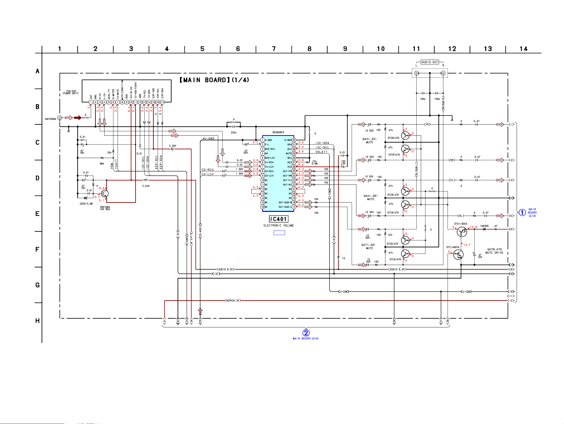
3-8. SCHEMATIC DIAGRAM – MAIN BOARD (1/4) – • See page 32 for IC Block Diagram. • See page 20 for Waveforms.
TU1
C484
CDX-S2210/S2210S/S2210X/S2250EE/SW330
J330
C474
C13
C5
JC1
R2
R3
R12
R13
FB1
R4
R5
C12
R1
C4
C6
D1
Q1
C7
L1
C404
C405
C406
C407
JC12
C11
C401
IC401
IC B/D
JC401
R405
R411
R410
R406
R407
R408
R409
C413
C412
R401
C431
C481
C471
C451
C441
C461
R431
R481
R471
R451
R441
R461
R432
R452
R442
R462
R482
R472
Q431
Q451
Q441
Q461
Q481
Q471
JC446
JC445
Q478
R433
R453
R443
Q479
C432
R463
C452
C442
C479
C462
D479
R479
(Page 26)
J1
CDX-S2210/S2210S/S2210X/S2250EE/SW330
(Page 27)
25 25
 Loading...