

SONY CDX-L380X Service Manual
CDX-L380X
SERVICE MANUAL
Ver 1.0 2002. 11
• The tuner and CD sections have no adjustments.
SPECIFICATIONS
AEP Model
UK Model
Model Name Using Similar Mechanism CDX-CA700/CA700X
CD Drive Mechanism Type MG-393XA-121//Q
Optical Pick-up Name KSS-720A
CD player section
Signal-to-noise ratio 90 dB
Frequency response 10 – 20,000 Hz
Wow and flutter Below measurable limit
Tuner section
FM
Tuning range 87.5 – 108.0 MHz
Aerial terminal External aerial connector
Intermediate frequency 10.7 MHz/450 kHz
Usable sensitivity 8 dBf
Selectivity 75 dB at 400 kHz
Signal-to-noise ratio 66 dB (stereo),
72 dB (mono)
Harmonic distortion at 1 kHz
0.6% (stereo),
0.3% (mono)
Separation 35 dB at 1 kHz
Frequency response 30 – 15,000 Hz
MW/LW
Tuning range MW: 531 – 1,602 kHz
LW: 153 – 279 kHz
Aerial terminal External aerial connector
Intermediate frequency 10.7 MHz/450 kHz
Sensitivity MW: 30 µV
LW: 40 µV
Power amplifier section
Outputs Speaker outputs
(sure seal connectors)
Speaker impedance 4 – 8 ohms
Maximum power output 45 W × 4 (at 4 ohms)
General
Outputs Audio outputs
Power aerial relay control
lead
Inputs Telephone ATT control lead
Tone controls Bass ±9 dB at 100 Hz
Treble ±9 dB at 10 kHz
Power requirements 12 V DC car battery
(negative ground)
Dimensions Approx. 178 × 50 × 177 mm
(w/h/d)
Mounting dimension Approx. 182 × 53 × 162 mm
(w/h/d)
Mass Approx. 1.2 kg
Supplied accessories Parts for installation and
connections (1 set)
Front panel case (1)
Design and specifications are subject to change without
notice.
9-874-229-01
2002K0400-1
© 2002. 11
FM/MW/LW COMPACT DISC PLAYER
Sony Corporation
e Vehicle Company
Published by Sony Engineering Corporation
1
CDX-L380X
SERVICE NOTES
CLASS 1
LASER PRODUCT
This label is located on the bottom of the chassis.
INVISIBLE LASER RADIATION WHEN OPENCAUTION
DO NOT STARE INTO BEAM OR
VIEW DIRECTLY WITH OPTICAL INSTRUMENTS
This label is located on the drive unit’s internal chassis.
When replacing the chassis (T.U) of mechanism deck which have
the “CAUTION LABEL” attached, please be sure to put a new
LABEL (OP CAUTION) (3-223-913-01) to the chassis (T.U).
NOTES ON HANDLING THE OPTICAL PICK-UP BLOCK
OR BASE UNIT
The laser diode in the optical pick-up block may suffer electrostatic
breakdown because of the potential difference generated by the
charged electrostatic load, etc. on clothing and the human body.
During repair, pay attention to electrostatic breakdown and also use
the procedure in the printed matter which is included in the repair
parts.
The flexible board is easily damaged and should be handled with
care.
TEST DISCS
This set can playback CD-R and CD-ROM discs. The following
test discs should be used to check the capability:
CD-R test disc TCD-R082LMT (Part No. J-2502-063-1)
CD-RW test disc TCD-W082L (Part No. J-2502-063-2)
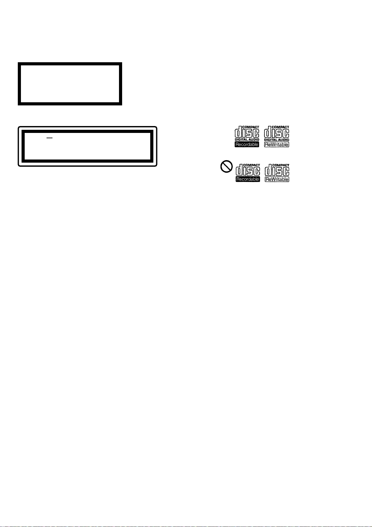
Notes on CD-R/CD-RW discs
• You can play CD-Rs (recordable CDs)/CD-RWs (re writable CDs)
designed for audio use on this unit.
Look for these marks to distinguish CD-Rs/CD-RWs for audio
use.
These marks denote that a disc is not for audio use.
• Some CD-Rs/CD-RWs (depending on the equipment used for
its recording or the condition of the disc) may not play on this
unit.
• You cannot play a CD-R/a CD-RW that is not finalized∗.
∗ A process necessary for a recorded CD-R/CD-RW disc to be
played on the audio CD player.
NOTES ON LASER DIODE EMISSION CHECK
The laser beam on this model is concentrated so as to be focused on
the disc reflective surface by the objective lens in the optical pickup block. Therefore, when checking the laser diode emission, observe from more than 30 cm away from the objective lens.
Notes on Chip Component Replacement
• Never reuse a disconnected chip component.
• Notice that the minus side of a tantalum capacitor may be dam-
aged by heat.
SAFETY-RELATED COMPONENT WARNING!!
COMPONENTS IDENTIFIED BY MARK 0 OR DOTTED LINE
WITH MARK 0 ON THE SCHEMATIC DIAGRAMS AND IN
THE PARTS LIST ARE CRITICAL TO SAFE OPERATION.
REPLACE THESE COMPONENTS WITH SONY PARTS WHOSE
PART NUMBERS APPEAR AS SHO WN IN THIS MANUAL OR
IN SUPPLEMENTS PUBLISHED BY SONY.
2
UNLEADED SOLDER
•
Boards requiring use of unleaded solder are printed with the lead
free mark (LF) indicating the solder contains no lead.
(Caution: Some printed circuit boards may not come printed with
the lead free mark due to their particular size.)
: LEAD FREE MARK
Unleaded solder has the following characteristics.
• Unleaded solder melts at a temperature about 40°C higher than
ordinary solder.
Ordinary soldering irons can be used but the iron tip has to be
applied to the solder joint for a slightly longer time.
Soldering irons using a temperature regulator should be set to
about 350°C.
Caution: The printed pattern (copper foil) may peel away if
the heated tip is applied for too long, so be careful!
• Strong viscosity
Unleaded solder is more viscous (sticky, less prone to flow)
than ordinary solder so use caution not to let solder bridges
occur such as on IC pins, etc.
• Usable with ordinary solder
It is best to use only unleaded solder but unleaded solder may
also be added to ordinary solder.
CDX-L380X
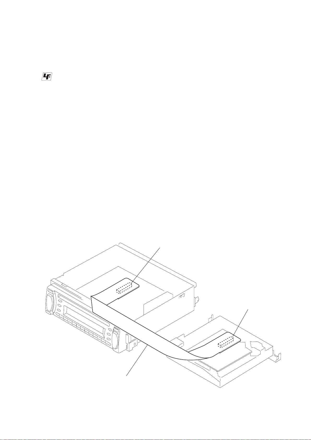
EXTENSION CABLE AND SERVICE POSITION
When repairing or servicing this set, connect the jig (extension cable)
as shown below.
• Connect the MAIN board (CNP301) and the SER V O board (CN1)
with the extension cable (Part No. J-2502-011-1).
MAIN BOARD
CNP301
SERVO BOARD
CN1
J-2502-011-1
3

CDX-L380X
TABLE OF CONTENTS
1. GENERAL
Location of controls................................................................. 5
Connections ............................................................................. 6
2. DISASSEMBLY
2-1. Sub Panel Assy.................................................................... 7
2-2. CD Mechanism Block ......................................................... 8
2-3. Main Board ......................................................................... 8
2-4. Heat Sink ............................................................................. 9
2-5. Chassis (T.U) Assy .............................................................. 9
2-6. Disc in Board .................................................................... 10
2-7. Servo Board....................................................................... 10
2-8. Arm Roller Assy ................................................................ 11
2-9. Floating Block Assy .......................................................... 11
2-10. Optical Pick-up Block ....................................................... 12
3. DIAGRAMS
3-1. IC Pin Description............................................................. 13
3-2. Block Diagram –CD Section–........................................... 15
3-3. Block Diagram –Tuner Section–....................................... 16
3-4. Block Diagram –Display Section–.................................... 17
3-5. Circuit Boards Location .................................................... 17
3-6. Printed Wiring Boards –CD Mechanism Section–............ 18
3-7. Schematic Diagram –CD Mechanism Section– ................ 20
3-8. Printed Wiring Board –Main Section– .............................. 21
3-9. Schematic Diagram –Main Section (1/2)– ........................ 22
3-10. Schematic Diagram –Main Section (2/2)– ........................ 23
3-11. Printed Wiring Board –Key Section–................................ 24
3-12. Schematic Diagram –Key Section–...................................25
3-13. IC Block Diagrams............................................................ 26
4. EXPLODED VIEWS
4-1. Chassis Section ................................................................. 28
4-2. Front panel Section ........................................................... 29
4-3. CD Mechanism Section (1) ...............................................30
4-4. CD Mechanism Section (2) ...............................................31
4-5. CD Mechanism Section (3) ...............................................32
5. ELECTRICAL PARTS LIST......................................... 33
4
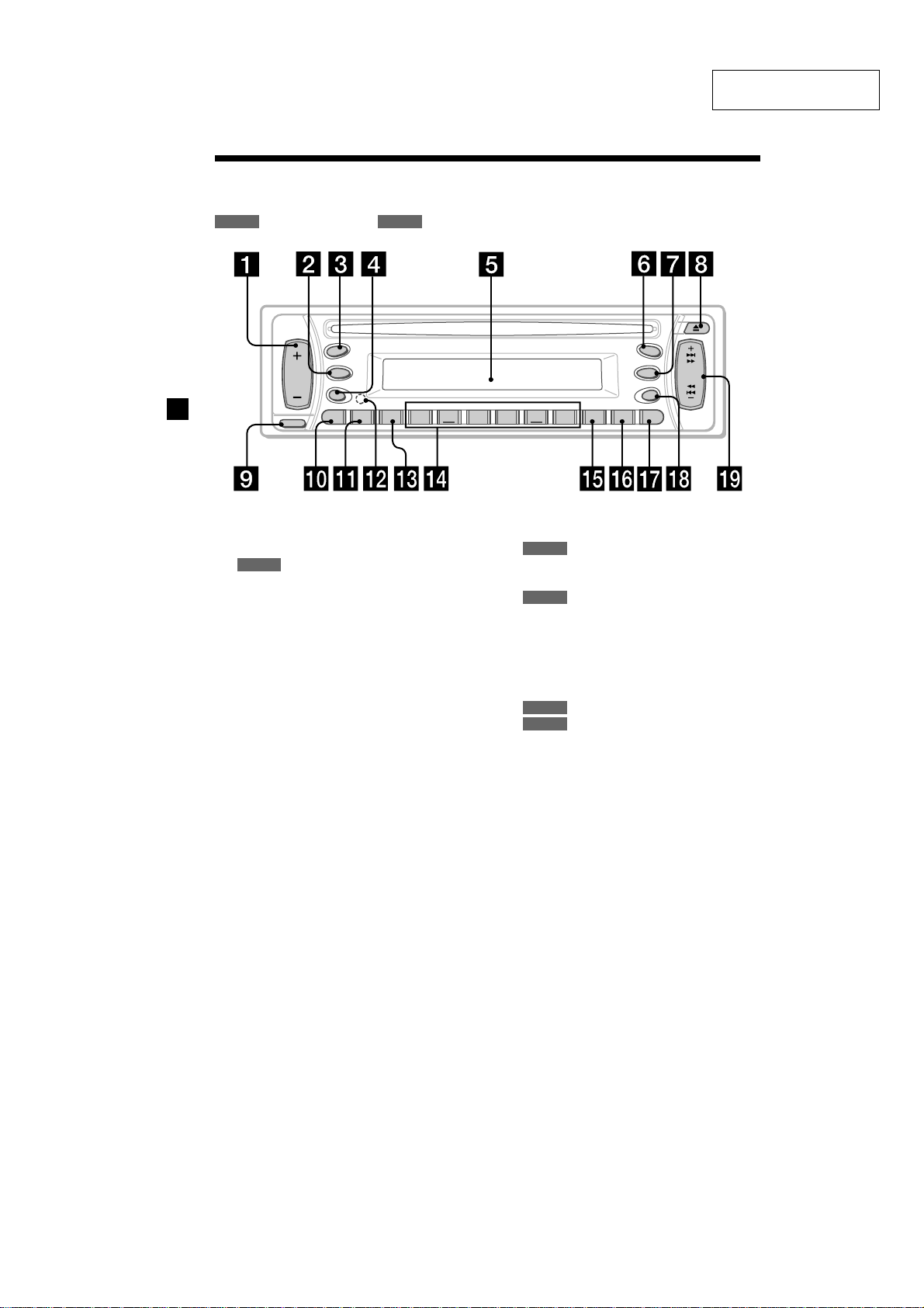
Location of controls
Refer to the pages listed for details.
CD RADIO
: During playback
SECTION 1
GENERAL
: During radio reception
CDX-L380X
This section is extracted
from instruction manual.
SOURCE
SRC
MODE
SEL
BTM
SENS
RELEASE
AT T
AF 1 2 3456TA
1 Volume +/– button 8, 13, 17
2 MODE button
RADIO
10, 11, 13
3 SRC (SOURCE) (TUNER/CD) button
8, 10, 11, 13
4 SEL (select) button 8, 15, 17, 18
5 Display window
6
MBP (My Best sound Position) button
18
7 D (D-BASS) button 18
8 Z (eject) button 8
9 RELEASE (front panel release) button 7
q; ATT (attenuate) button 17
qa SENS/BTM button 10, 11, 13
qs RESET button (located on the front side of
the unit, behind the front panel) 6
qd AF button 12, 13
MBP
D-BASS
D
REP SHUF
CDX-L380X/CDX-L400X
CDX-L410/CDX-L420V
OFF
PTY DSPL
qf Number buttons 17
CD
(3) REP 9
(4) SHUF 9
RADIO
10, 11, 12, 13, 15
qg TA button 13
qh PTY (programme type) button 14
qj DSPL (display mode change) button
8, 9, 11
qk OFF button* 7, 8
ql SEEK/AMS +/– button
CD
8
RADIO
10, 11, 12, 14
* Warning when installing in a car
without an ACC (accessory) position
on the ignition key switch
Be sure to press (OFF) on the unit for
2 seconds to turn off the clock display
after turning off the engine.
Otherwise, the clock display does not turn
off and this causes battery drain.
SEEK
AMS
4
5
CDX-L380X
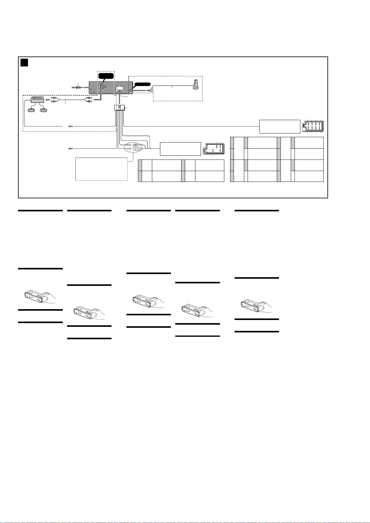
Connections
3
1
*
from car aerial
von Autoantenne
de l’antenne de la voiture
dall’antenna dell’auto
van een auto-antenne
Max. supply current 0.3 A
max. Versorgungsstrom 0,3 A
Courant d’alimentation maximum 0,3 A
Alimentazione massima fornita 0,3 A
Max. voedingsstroom 0,3 A
3
*
Cautions
•This unit is designed for negative earth 12 V DC
operation only.
•Do not get the wires under a screw, or caught in
moving parts (e.g. seat railing).
•Before making connections, turn the car ignition
off to avoid short circuits.
•Connect the power connecting cord 8 to the unit
and speakers before connecting it to the auxiliary
power connector.
• Run all earth wires to a common earth point.
•Be sure to insulate any loose unconnected wires
with electrical tape for safety.
Notes on the power supply cord (yellow)
•When connecting this unit in combination with
other stereo components, the connected car
circuit’s rating must be higher than the sum of
each component’s fuse.
•When no car circuits are rated high enough,
connect the unit directly to the battery.
Parts list (1)
The numbers in the list are keyed to those in the
instructions.
Cautions
Handle the bracket 1 carefully to avoid injuring
your fingers.
Connection example (2)
Connection diagram (3)
A
To AMP REMOTE IN of an optional power
amplifier (CDX-L380X/L400X only)
This connection is only for amplifiers. Connecting
any other system may damage the unit.
B
To the interface cable of a car telephone
Warning
If you have a power aerial without a relay box,
connecting this unit with the supplied power
connecting cord 8 may damage the aerial.
Notes on the control leads
• The power aerial control lead (blue) supplies +12 V
DC when you tur n on the tuner or when you
activate the AF (Alternative Frequency), TA (Traffic
Announcement) function.
•When your car has built-in FM/MW/LW aerial in
the rear/side glass, connect the power aerial
control lead (blue) or the accessory power input
lead (red) to the power terminal of the existing
aerial booster. For details, consult your dealer.
•A power aerial without a relay box cannot be used
with this unit.
Memory hold connection
When the yellow power input lead is connected,
power will always be supplied to the memory circuit
even when the ignition switch is turned off.
Notes on speaker connection
• Before connecting the speakers, turn the unit off.
• Use speakers with an impedance of 4 to 8 ohms,
and with adequate power handling capacities to
avoid its damage.
• Do not connect the speaker terminals to the car
chassis, or connect the terminals of the right
speakers with those of the left speaker.
• Do not connect the earth lead of this unit to the
negative (–) terminal of the speaker.
• Do not attempt to connect the speakers in parallel.
• Connect only passive speakers. Connecting active
speakers (with built-in amplifiers) to the speaker
terminals may damage the unit.
•To avoid a malfunction, do not use the built-in
speaker wires installed in your car if the unit shares
a common negative (–) lead for the right and left
speakers.
• Do not connect the unit’s speaker cords to each
other.
6
2
*
Blue/white striped
Blau-weiß gestreift
Rayé bleu/blanc
A strisce blu e bianche
AMP REM
A
ATT
B
Vorsicht
•Dieses Gerät ist ausschließlich für den Betrieb bei
12 V Gleichstrom (negative Erdung) bestimmt.
•Achten Sie darauf, daß die Kabel nicht unter einer
Schraube oder zwischen beweglichen Teilen wie
z. B. in einer Sitzschiene eingeklemmt werden.
•Schalten Sie, bevor Sie irgendwelche Anschlüsse
vornehmen, die Zündung des Fahrzeugs aus, um
Kurzschlüsse zu vermeiden.
•Verbinden Sie das Stromversorgungskabel 8 mit
dem Gerät und den Lautsprechern, bevor Sie es
mit dem Hilfsstromanschluß verbinden.
• Schließen Sie alle Erdungskabel an einen
gemeinsamen Massepunkt an.
•Aus Sicherheitsgründen müssen alle losen, nicht
angeschlossenen Drähte mit Isolierband abisolier t
werden.
Hinweise zum Stromversorgungskabel (gelb)
•Wenn Sie dieses Gerät zusammen mit anderen
Stereokomponenten anschließen, muß der
Autostromkreis, an den die Geräte angeschlossen
sind, eine höhere Leistung aufweisen als die
Summe der Sicherungen der einzelnen
Komponenten.
•Wenn kein Autostromkreis eine so hohe Leistung
aufweist, schließen Sie das Gerät direkt an die
Batterie an.
Teileliste (1)
Die Nummern in der Liste sind dieselben wie im
Erläuterungstext.
Sicherheitshinweise
Seien Sie beim Umgang mit der Halterung 1
vorsichtig, damit Sie sich nicht die Hände verletzen.
Blauw/wit gestreept
Light blue
Hellblau
Bleu ciel
Azzurro
Hemelsblauw
See “Power connection diagram” in the back for details.
Näheres dazu finden Sie im „Stromanschlußdiagramm”.
Blättern Sie dazu bitte um.
Schéma de connexion d’alimentation
Voir le “
pour plus de détails.
Per ulteriori informazioni, vedere “Diagramma dei
collegamenti di alimentazione” che si trova sul retro.
Zie “Voedingsaansluitschema” op de achterkant voor
meer details.
Anschlußbeispiel (2)
Anschlußdiagramm (3)
A
An AMP REMOTE IN des gesondert erhältlichen
Endverstärkers (Nur CDX-L380X/L400X)
Dieser Anschluß ist ausschließlich für Verstärker
gedacht. Schließen Sie nichts anderes daran an.
Andernfalls kann das Gerät beschädigt werden.
B
An Schnittstellenkabel eines Autotelefons
Warnung
Wenn Sie eine Motorantenne ohne Relaiskästchen
verwenden, kann durch Anschließen dieses Geräts
mit dem mitgelieferten Stromversorgungskabel 8
die Antenne beschädigt werden.
Hinweise zu den Steuerleitungen
• Die Motorantennen-Steuerleitung (blau) liefert +
12 V Gleichstrom, wenn Sie den Tuner einschalten
oder die AF- (Alternativfrequenzsuche) oder die
TA-Funktion (Verkehrsdurchsagen) aktivieren.
• Wenn das Fahrzeug mit einer in der Heck-/
Seitenfensterscheibe integrierten FM (UKW)/MW/
LW-Antenne ausgestattet ist, schließen Sie die
Motorantennen-Steuerleitung (blau) oder die
Zubehörstromversorgungsleitung (rot) an den
Stromversorgungsanschluß des vorhandenen
Antennenverstärkers an. Näheres dazu erfahren
Sie bei Ihrem Händler.
• Es kann nur eine Motorantenne mit Relaiskästchen
angeschlossen werden.
Stromversorgung des Speichers
Wenn die gelbe Stromversorgungsleitung
angeschlossen ist, wird der Speicher stets (auch bei
ausgeschalteter Zündung) mit Strom versorgt.
Hinweise zum Lautsprecheranschluß
• Schalten Sie das Gerät aus, bevor Sie die
Lautsprecher anschließen.
•Verwenden Sie Lautsprecher mit einer Impedanz
zwischen 4 und 8 Ohm und ausreichender
Belastbarkeit. Ansonsten können die Lautsprecher
beschädigt werden.
•Verbinden Sie die Lautsprecheranschlüsse nicht mit
dem Wagenchassis, und verbinden Sie auch nicht
die Anschlüsse des rechten mit denen des linken
Lautsprechers.
•Verbinden Sie die Masseleitung dieses Geräts nicht
mit dem negativen (–) Lautsprecheranschluß.
•Versuchen Sie nicht, Lautsprecher parallel
anzuschließen.
• An die Lautsprecheranschlüsse dieses Geräts
dürfen nur Passivlautsprecher angeschlossen
werden. Schließen Sie keine Aktivlautsprecher
(Lautsprecher mit eingebauten Verstärkern) an, da
diese sonst beschädigt werden können.
• Um Fehlfunktionen zu vermeiden, verwenden Sie
nicht die im Fahrzeug installierten, integrier ten
Lautsprecherleitungen, wenn am Ende eine
gemeinsame negative (–) Leitung für den rechten
und den linken Lautsprecher verwendet wird.
•Verbinden Sie nicht die Lautsprecherkabel des
Geräts miteinander.
AUDIO OUT
REAR
AUDIO OUT
REAR
REMOTE IN
Fuse (10 A)
Sicherung (10 A)
Fusible (10 A)
Fusibile (10 A)
Zekering (10 A)
8
” au verso
4
5
Positions 1, 2, 3 and 6 do not have pins.
An Position 1, 2, 3 und 6 befinden sich keine Stifte.
Les positions 1, 2, 3 et 6 ne compor tent pas de broches.
Le posizioni 1, 2, 3 e 6 non hanno piedini.
De posities 1, 2, 3 en 6 hebben geen pins.
Précautions
•Cet appareil est conçu pour fonctionner sur un
courant continu de 12 V avec masse négative.
•Evitez de fixer des vis sur les câbles ou de coincer
ceux-ci dans des pièces mobiles (par exemple,
armature de siège).
•Avant d’effectuer des raccordements, éteignez le
moteur pour éviter les courts-circuits.
•Branchez le cordon d’alimention 8 sur l’appareil
et les haut-parleurs avant de le brancher sur le
connecteur d’alimentation auxiliaire.
• Rassemblez tous les fils de terre en un point de
masse commun.
•Veillez à isoler tout fil ou câble non connecté avec
du chatterton approprié.
Remarques sur le cordon d’alimentation (jaune)
• Lorsque cet appareil est raccordé à d’autres
éléments stéréo, la valeur nominale des circuits de
la voiture raccordée doit être supérieure à la
somme des fusibles de chaque élément.
•Si aucun circuit de la voiture n’est assez puissant,
raccordez directement l’appareil à la batterie.
Liste des composants (1)
Les numéros de l’illustration correspondent à ceux
des instructions.
Avertissements
Manipulez précautionneusement le support 1
pour éviter de vous blesser aux doigts.
Exemple de raccordement (2)
Schémas de connexion (3)
A
Au niveau du AMP REMOTE IN d’un
amplificateur de puissance facultatif (CDXL380X/L400X seulement)
Ce raccordement existe seulement pour les
amplificateurs. Le raccordement à tout autre
système peut endommager l’appareil.
B
Vers le cordon de liaison d’un téléphone de
voiture
Avertissement
Si vous disposez d’une antenne électrique sans
boîtier de relais, le branchement de cet appareil au
moyen du cordon d’alimentation fourni 8 risque
d’endommager l’antenne.
Remarques sur les fils de commande
• Le fil de commande (bleu) fournit du courant
continu de +12 V lorsque vous allumez le sélecteur
de canaux ou lorsque vous activez la fonction TA
(informations circulation) en AF (fréquence
alternative).
• Lorsque votre voiture est équipée d’une antenne
FM/MW/LW intégrée dans la vitre arrière/latérale,
raccordez le fil de commande de l’antenne (bleu)
ou l’entrée d’alimentation des accessoires (rouge)
au bornier de l’amplificateur d’antenne existant.
Pour plus de détails, consultez votre revendeur.
• Une antenne électrique sans boîtier de relais ne
peut pas être utilisée avec cet appareil.
Connexion pour la conservation de la mémoire
Lorsque le fil d’entrée d’alimentation jaune est
connecté, le circuit de la mémoire est alimenté en
permanence même si la clé de contact est en
position d’arrêt.
Remarques sur la connexion des haut-parleurs
•Avant de raccorder les haut-parleurs, mettre
l’appareil hors tension.
•Utiliser des haut-parleurs ayant une impédance de
4 à 8 ohms et une capacité adéquate sous peine de
les endommager.
• Ne pas raccorder les bornes du système de hautparleurs au châssis de la voiture et ne pas
connecter les bornes du haut-parleur droit à celles
du haut-parleur gauche.
• Ne pas raccorder le câble de masse de cet appareil
à la borne négative (–) du haut-parleur.
• Ne pas tenter de raccorder les haut-parleurs en
parallèle.
• Ne pas connecter d’enceintes acoustiques actives
(avec amplificateurs intégrés) aux bornes
d’enceinte de cet appareil, pour éviter
d’endommager les enceintes. Veiller à raccorder
des enceintes passives.
•Pour éviter tout dysfonctionnement, n’utilisez pas
les fils des haut-parleurs intégrés installés dans
votre voiture si l’appareil dispose d’un fil négatif
commun (–) pour les haut-parleurs droit et gauche.
• Ne raccordez pas entre eux les cordons des hautparleurs de l’appareil.
Yellow
Blauw
Gelb
Jaune
Giallo
Geel
Blue
Blau
Bleu
Blu
continuous power supply
permanente Stromversorgung
alimentation continue
alimentazione continua
Motorantennensteuerung
comando dell’antenna elettrica
automatische antenne
Insert with the cord upwards.
Mit dem Kabel nach oben einsetzen!
Insérez avec le câble vers le haut.
Inserire con il cavo rivolto verso l’alto.
Inbrengen met het snoer naar boven.
from the car’s power connector
vom Stromanschluß des Fahrzeugs
du connecteur d’alimentation de la voiture
dal connettore di alimentazione dell’auto
van de autovoedingsstekker
continu voeding
power aerial control
antenne électrique
7
Schwarz
8
Attenzione
•Questo apparecchio è stato progettato per l’uso
solo a 12 V CC con massa negativa.
•Evitare che i cavi rimangano bloccati da una vite o
incastrati nelle parti mobili (ad esempio nelle
guide scorrevoli dei sedili).
•Prima di effettuare i collegamenti, spegnere il
motore dell’automobile onde evitare di causare
cortocircuiti.
•Collegare il cavo di collegamento
dell’alimentazione 8 all’apparecchio e ai
diffusori prima di collegarlo al connettore di
alimentazione ausiliare.
• Portare tutti i cavi di massa a un punto di
massa comune.
•Per sicurezza, assicurarsi di isolare qualsiasi cavo
non collegato mediante apposito nastro.
Note sul cavo di alimentazione (giallo)
•Se questo apparecchio viene collegato in
combinazione con altri componenti stereo, la
potenza nominale dei circuiti dell’automobile
deve essere superiore a quella prodotta dalla
somma dei fusibili di ciascun componente.
•Se la potenza nominale dei circuiti
dell’automobile non è sufficiente, collegare
l’apparecchio direttamente alla batteria.
Elenco dei componenti (1)
I numeri nella lista corrispondono a quelli ripor tati
nelle istruzioni.
Attenzione
Maneggiare la staffa 1 con cautela per evitare di
ferirsi le mani.
Esempi di collegamento (2)
Schema di collegamento (3)
A
A AMP REMOTE IN di un amplificatore di
potenza opzionale (Solo CDX-L380X/L400X)
Questo collegamento è riservato esclusivamente
agli amplificatori. Non collegare un tipo di
sistema diverso onde evitare di causare danni
all’apparecchio.
B
Al cavo interfaccia di un telefono per auto
Avvertenza
Quando si collega l’apparecchio con il cavo di
alimentazione in dotazione 8, si potrebbe
danneggiare l’antenna elettrica se questa non ha la
scatola di relè.
Note sui cavi di controllo
• Il cavo (blu) di controllo dell’antenna elettrica
fornisce alimentazione pari a +12 V CC quando si
attiva il sintonizzatore o la funzione TA (notiziario
sul traffico) AF (frequenza alternativa).
• Se l’automobile è dotata di antenna FM/MW/LW
incorporata nel vetro posteriore/laterale, collegare
il cavo (blu) di controllo dell’antenna elettrica o il
cavo (rosso) di ingresso dell’alimentazione
opzionale al terminale di alimentazione del
preamplificatore dell’antenna esistente. Per
ulteriori informazioni, consultare il proprio
fornitore.
• Non è possibile usare un’antenna elettrica senza
scatola a relè con questo apparecchio.
Collegamento per la conservazione della memoria
Quando il cavo di ingresso alimentazione giallo è
collegato, viene sempre fornita alimentazione al
circuito di memoria anche quando l’interruttore di
accensione è spento.
Note sul collegamento dei diffusori
•Prima di collegare i diffusori spegnere
l’apparecchio.
• Usare diffusori di impedenza compresa tra 4 e 8
ohm e con capacità di potenza adeguata,
altrimenti i diffusori potrebbero venir danneggiati.
• Non collegare i terminali del sistema diffusori al
telaio dell’auto e non collegare i terminali del
diffusore destro a quelli del diffusore sinistro.
• Non collegare il cavo di terra di questo
apparecchio al terminale negativo (–) del diffusore.
• Non collegare i diffusori in parallelo.
• Assicurarsi di collegare soltanto diffusori passivi,
poiché il collegamento di diffusori attivi, dotati di
amplificatori incorporati, ai terminali dei diffusori
potrebbe danneggiare l’apparecchio.
•Per evitare problemi di funzionamento, non
utilizzare i cavi dei diffusori incorporati installati
nell’automobile se l’apparecchio condivide un cavo
comune negativo (–) per i diffusori destro e
sinistro.
• Non collegare fra loro i cavi dei diffusori
dell’apparecchio.
Rouge
Rosso
Zwart
Red
Rot
Rood
Black
Noir
Nero
1
*
Note for the aerial connecting
If your car aerial is an ISO
(International Organisation for
Standardisation) type, use the supplied
adaptor
First connect the car aerial to the
supplied adaptor, then connect it to
the aerial jack of the master unit.
2
*
RCA pin cord (not supplied)
3
*
CDX-L380X/L400X only
4
*
CDX-L410/L420V only
1
*
Hinweis zum Anschließen der Antenne
Wenn Ihre Fahrzeugantenne der
ISO-Norm (ISO = International
Organization for Standardization Internationale
Normungsgemeinschaft) entspricht,
schließen Sie sie mit Hilfe des
4
*
mitgelieferten Adapters
Verbinden Sie zuerst die
Fahrzeugantenne mit dem
mitgelieferten Adapter, und verbinden
Sie diesen dann mit der
Antennenbuchse des Hauptgeräts.
2
Cinchkabel (nicht mitgeliefert)
*
3
*
Nur CDX-L380X/L400X
4
*
Nur CDX-L410/L420V
48
switched power supply
geschaltete Stromversorgung
alimentation commutée
alimentazione commutata
geschakelde voeding
earth
Masse
masse
terra
aarding
1
*
Remarque sur le raccordement de
l’antenne
Si votre antenne de voiture est de type
6
to connect it.
57
1
2
3
4
Negative polar ity positions 2, 4, 6, and 8 have striped cords.
An den negativ gepolten Positionen 2, 4, 6 und 8 befinden sich gestreifte Adern.
Les positions de polarité négative 2, 4, 6 et 8 sont dotées de cordons rayés.
Le posizioni a polar ità negativa 2, 4, 6 e 8 hanno cavi rigati.
De negatieve posities 2, 4, 6 en 8 hebben gestreepte kabels.
ISO (Organisation inter nationale de
normalisation), utilisez l’adaptateur
6
pour la raccorder.
fourni
Raccordez d’abord l’antenne de
voiture à l’adaptateur fourni et,
ensuite, à la prise d’antenne de
l’appareil principal.
2
*
Cordon à broche RCA (non fourni)
3
*
CDX-L380X/L400X seulement
4
*
CDX-L410/L420V seulement
1
*
Nota per il collegamento dell’antenna
Se l’antenna dell’auto è di tipo ISO
(International Organization
Standardization), utilizzare
6
in dotazione per
l’adattatore
6
an.
collegarla.
Collegare prima l’antenna della
macchina all’adattatore in dotazione,
quindi collegarla alla presa
dell’antenna dell’apparecchio
principale.
2
Cavo a piedini RCA (non in dotazione)
*
3
*
Solo CDX-L380X/L400X
4
*
Solo CDX-L410/L420V
from the car’s speaker connector
vom Lautsprecheranschluß des Fahrzeugs
du connecteur de haut-parleur de la voiture
dal connettore del diffusore dell’auto
van de autoluidsprekerstekker
Speaker, Rear, Right
Lautsprecher hinten rechts
haut-parleur, arrière, droit
+
Diffusore, posteriore, destro
Purple
Luidspreker, achter, rechts
Violett
Mauve
Speaker, Rear, Right
Viola
Lautsprecher hinten rechts
Paars
haut-parleur, arrière, droit
–
Diffusore, posteriore, destro
Luidspreker, achter, rechts
Speaker, Front, Right
Lautsprecher vorne rechts
haut-parleur, avant, droit
+
Grey
Diffusore, anteriore, destro
Grau
Luidspreker, voor, rechts
Gris
Speaker, Front, Right
Grigio
Lautsprecher vorne rechts
Grijs
haut-parleur, avant, droit
–
Diffusore, anteriore, destro
Luidspreker, voor, rechts
Let op!
•Dit apparaat is ontworpen voor gebruik op
gelijkstroom van een 12 Volts auto-accu, negatief
geaard.
•Zorg ervoor dat de draden niet onder een schroef
of tussen bewegende onderdelen (b.v. zetelrail)
terechtkomen.
•Alvorens aansluitingen te verrichten moet u het
contact afzetten om kortsluiting te vermijden.
•Sluit het netsnoer 8 aan op het toestel en de
luidsprekers vooraleer u het op de
hulpvoedingsaansluiting aansluit.
• Sluit alle aarddraden op een
gemeenschappelijk aardpunt aan.
•Voorzie niet aangesloten draden om
veiligheidsredenen altijd van isolatietape.
Opmerkingen bij de voedingskabel (geel)
•Wanneer u dit toestel aansluit samen met andere
componenten, moet het vermogen van de
aangesloten autostroomkring groter zijn dan de
som van de zekeringen van elke component
afzonderlijk.
•Wanneer het vermogen ontoereikend is, moet u
het toestel rechtstreeks aansluiten op de batterij.
Onderdelenlijst (1)
De nummers in de afbeelding verwijzen naar die in
de montage-aanwijzingen.
Opgelet
Houd de beugel 1 voorzichtig vast zodat u uw
vingers niet verwondt.
Voorbeeldaansluitingen (2)
Aansluitschema (3)
A
Naar AMP REMOTE IN van een los verkrijgbare
vermogensversterker (Alleen voor de CDXL380X/L400X)
Deze aansluiting is alleen bedoeld voor
versterkers. Door een ander systeem aan te
sluiten kan het toestel worden beschadigd.
B
Naar het interface-snoer van een autotelefoon
Opgelet
Indien u een elektrische antenne heeft zonder
relaiskast, kan het aansluiten van deze eenheid met
het bijgeleverde netsnoer de antenne
beschadigen.
Opmerking betreffende de aansluitsnoeren
• De antennevoedingskabel (blauw) levert +12 V
gelijkstroom wanneer u de tuner aanschakelt of de
AF (Alternative Frequency), TA (Traffic
Announcement) functie activeert.
•Wanneer uw auto is uitgerust met een FM/MW/
LW-antenne in de achterruit/voorruit, moet u de
antennevoedingskabel (blauw) of de
hulpvoedingskabel (rood) aansluiten op de
voedingsingang van de bestaande
antenneversterker. Raadpleeg uw dealer voor
meer details.
• Met dit apparaat is het niet mogelijk een
automatische antenne zonder relaishuis te
gebruiken.
Instandhouden van het geheugen
Zolang de gele stroomdraad is aangesloten, blijft de
stroomvoorziening van het geheugen intact, ook
wanneer het contact van de auto wordt
uitgeschakeld.
Opmerkingen betreffende het aansluiten van de
luidsprekers
• Zorg dat het apparaat is uitgeschakeld, alvorens de
luidsprekers aan te sluiten.
• Gebruik luidsprekers met een impedantie van 4 tot
8 Ohm en let op dat die het vermogen van de
versterker kunnen verwerken. Als dit wordt
verzuimd, kunnen de luidsprekers ernstig
beschadigd raken.
•Verbind in geen geval de aansluitingen van de
luidsprekers met het chassis van de auto en sluit de
aansluitingen van de rechter en linker luidspreker
niet op elkaar aan.
•Verbind de massakabel van dit toestel niet met de
negatieve (–) aansluiting van de luidspreker.
•Probeer nooit de luidsprekers parallel aan te
sluiten.
•Sluit geen actieve luidsprekers (met ingebouwde
versterkers) aan op de luidspreker-aansluiting van
dit apparaat. Dit zal leiden tot beschadiging van
de actieve luidsprekers. Sluit dus altijd uitsluitend
luidsprekers zonder ingebouwde versterker aan.
• Om defecten te vermijden mag u de bestaande
luidsprekerbedrading in uw auto niet gebr uiken
wanneer er een gemeenschappelijke negatieve (–)
draad is voor de rechter en linker luidsprekers.
•Verbind de luidsprekerdraden niet met elkaar.
1
*
Opmerking bij de antenne-aansluiting
Indien uw wagen is uitgerust met een
antenne van het type ISO
(International Organisation for
Standardization), moet u die
aansluiten met behulp van de
meegeleverde adaptor
Sluit eerst de auto-antenne aan op de
meegeleverde adaptor en vervolgens
de antennestekker op het
hoofdtoestel.
2
*
Tulpstekkersnoer (niet bijgeleverd)
3
*
Alleen voor de CDX-L380X/L400X
4
*
Alleen voor de CDX-L410/L420V
5
+
White
Weiß
Blanc
Bianco
Wit
6
–
7
+
Green
Grün
Vert
Verde
Groen
8
–
6
.
13 57
24 68
Speaker, Front, Left
Lautsprecher vorne links
haut-parleur, avant, gauche
Diffusore, anteriore, sinistro
Luidspreker, voor, links
Speaker, Front, Left
Lautsprecher vorne links
haut-parleur, avant, gauche
Diffusore, anteriore, sinistro
Luidspreker, voor, links
Speaker, Rear, Left
Lautsprecher hinten links
haut-parleur, arrière, gauche
Diffusore, posteriore, sinistro
Luidspreker, achter, links
Speaker, Rear, Left
Lautsprecher hinten links
haut-parleur, arrière, gauche
Diffusore, posteriore, sinistro
Luidspreker, achter, links
6
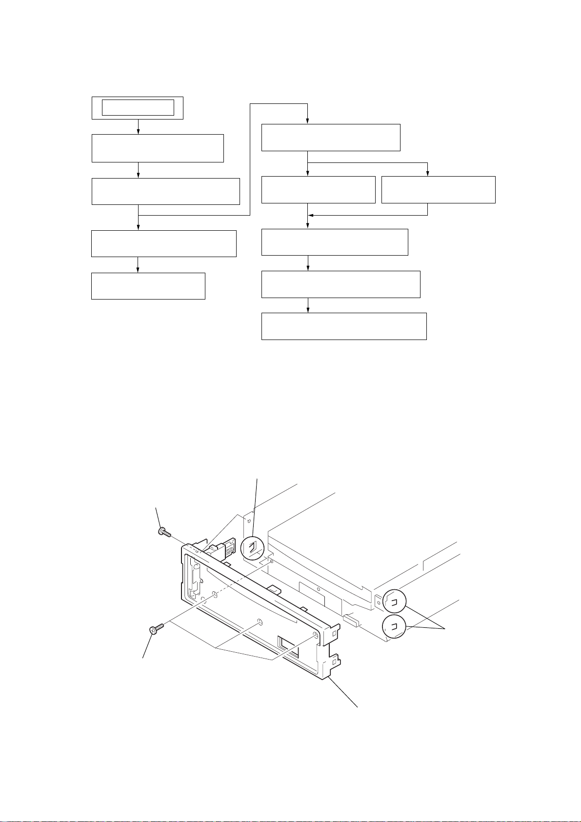
SECTION 2
DISASSEMBLY
Note : This set can be disassemble according to the following sequence.
SET
2-5. CHASSIS (T.U) ASSY
2-1. SUB PANEL ASSY
(Page 7)
(Page 9)
CDX-L380X
2-2. CD MECHANISM BLOCK
(Page 8)
2-3. MAIN BOARD
(Page 8)
2-4. HEAT SINK
(Page 9)
2-6. DISC IN BOARD
(Page 10)
2-8. ARM ROLLER ASSY
(Page 11)
2-9. FLOATING BLOCK ASSY
(Page 11)
2-10. OPTICAL PICK-UP BLOCK
(Page 12)
Note : Follow the disassembly procedure in the numerical order given.
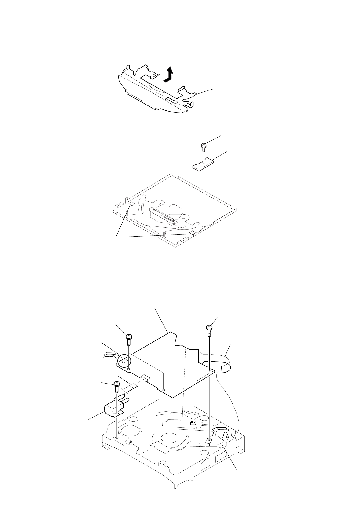
2-1. SUB PANEL ASSY
2-7. SERVO BOARD
(Page 10)
2
PTT 2.6x6
1
PTT 2.6x6
3
claw
5
sub panel assy
4
claws
7
CDX-L380X
6
6
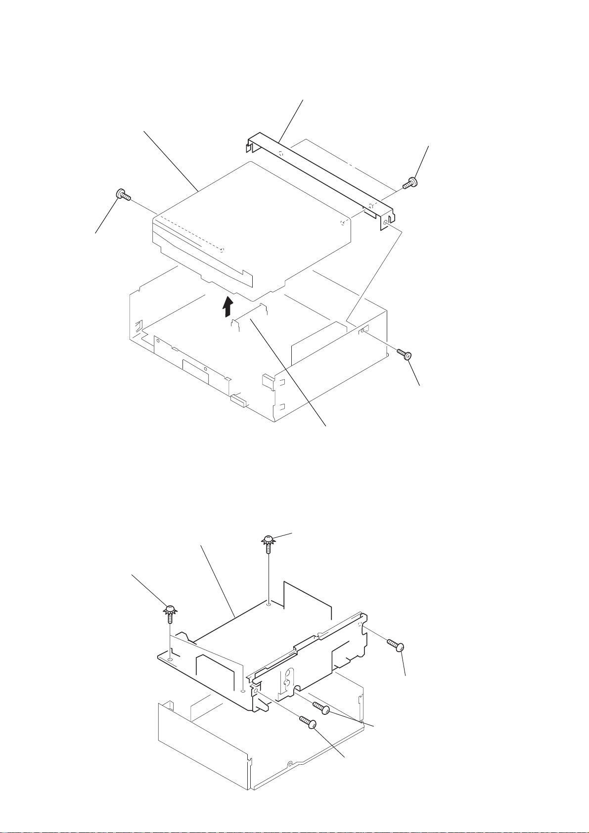
2-2. CD MECHANISM BLOCK
5
CD mechanism block
2
PTT 2.6x6
7
bracket (CD)
6
PTT 2.6x
2-3. MAIN BOARD
5
ground point screws
(PTT 2.6x6)
3
6
MAIN board
4
CNP301
4
ground point screw
(PTT 2.6x6)
1
PTT 2.6x6
3
PTT 2.6x
1
PTT 2.6x6
2
PTT 2.6x6
8
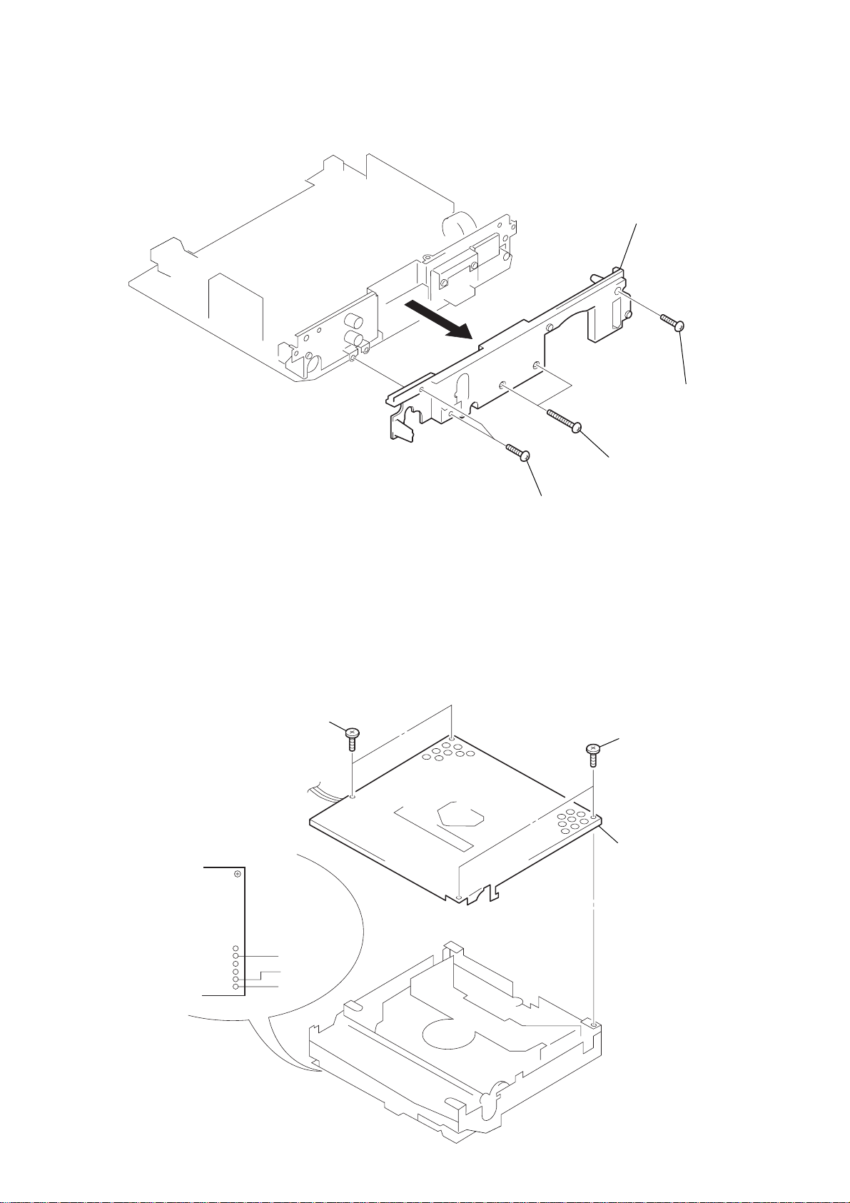
2-4. HEAT SINK
2
4
heat sink
CDX-L380X
3
PTT 2.6x1
2-5. CHASSIS (T.U) ASSY
1
Unsolder the
lead wires.
2
P 2x3
1
PTT 2.6x12
2
PTT 2.6x16
3
P 2x3
4
chassis (T.U) assy
black
red
white
9
CDX-L380X
2-6. DISC IN BOARD
4
guide (disc)
1
PS 2x3
2
DISC IN board
2-7. SERVO BOARD
2
Removal the solders.
3
P 2x3
3
claws
5
PS 2x4
1
CN3
7
SERVO board
6
PS 2x4
8
connector
10
4
loading motor assy
optical pick-up block
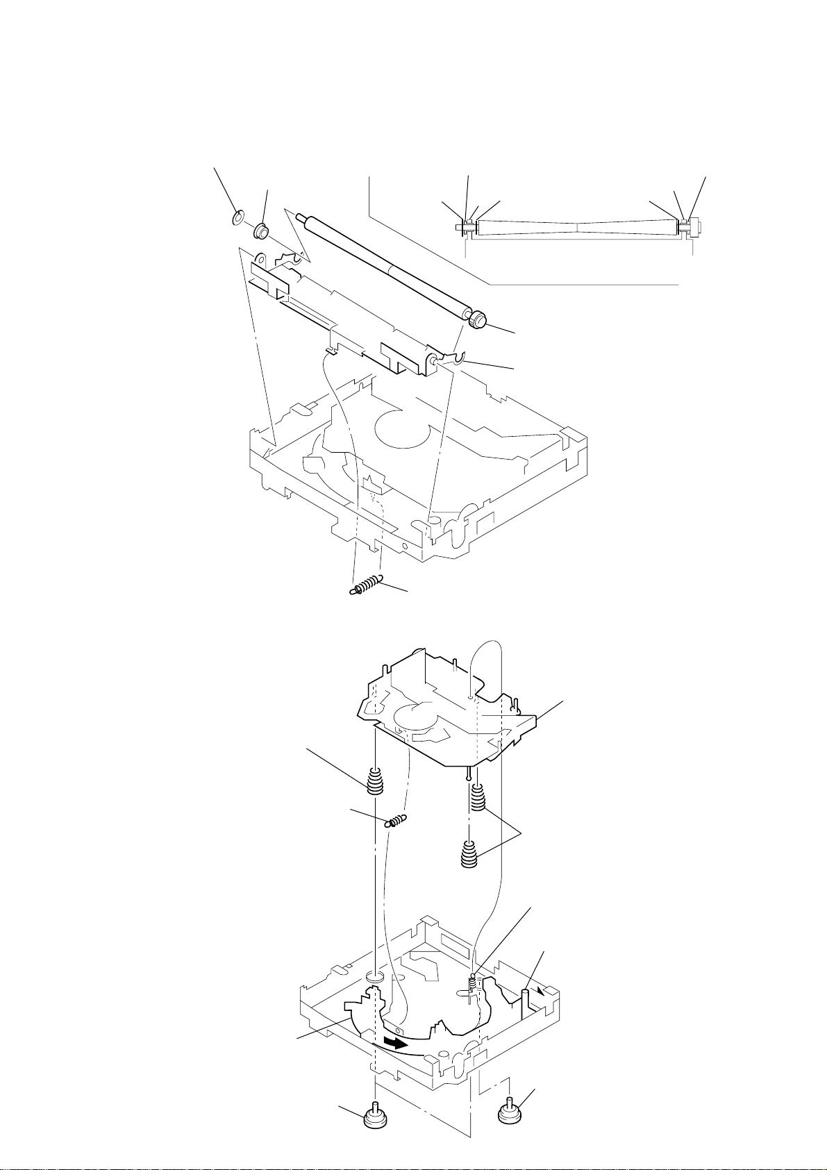
2-8. ARM ROLLER ASSY
• When installing, take note of the positions
arm (roller) and washers. (Fig. 1)
3
retaing ring (roller)
4
bearing (roller)
bearing (roller)
retaing ring (roller)
washer (RA)
arm
Fig. 1
5
shaft roller assy
2
arm (roller T)
washer (RA)
CDX-L380X
bearing (roller)
arm
2-9. FLOATING BLOCK ASSY
8
compression spring (FL)
1
tension spring (KF1)
1
tension spring (RA3)
7
floating block assy
9
compression spring (FL)
2
tension spring (KR1)
5
Fit lever (D) in the
direction of the arrow.
6
Turn loading ring in the
direction of the arrow.
4
damper (T)
3
damper (T)
11
CDX-L380X
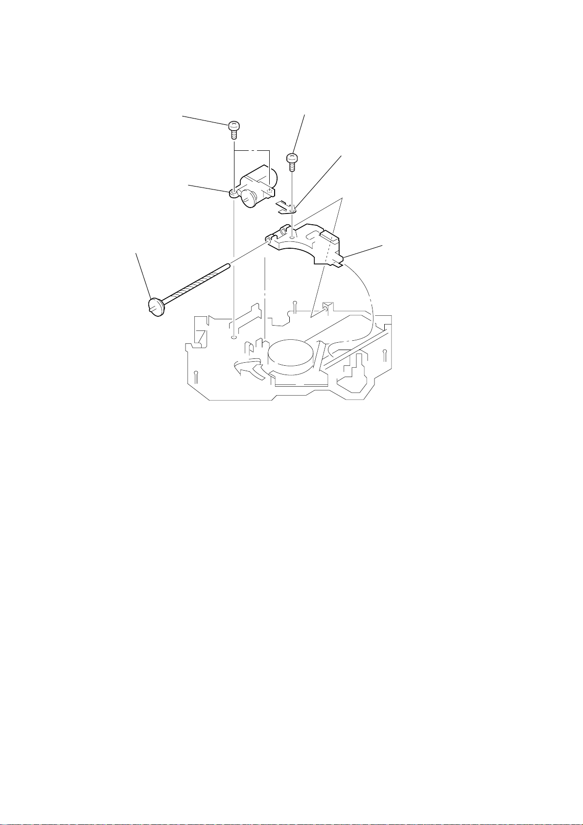
2-10. OPTICAL PICK-UP BLOCK
1
P 2x3
2
sled motor assy
6
shaft (feed) assy
4
P 2x3
5
leaf spring (feed)
3
optical pick-up block
12
 Loading...