

Sony CDXGT-820-IP Service manual
CDX-GT820IP
SERVICE MANUAL
Ver. 1.0 2007.12
• The tuner and CD sections have no adjustments.
AUDIO POWER SPECIFICATIONS POWER OUTPUT
AND TOTAL HARMONIC DISTORTION
23.2 watts per channel minimum continuous average power into
4 ohms, 4 channels driven from 20 Hz to 20 kHz with no more
than 5% total harmonic distortion.
CD Player section
Signal-to-noise ratio: 120 dB
Frequency response: 10 – 20,000 Hz
Wow and fl utter: Below measurable limit
Tuner section
FM
Tuning range:
87.5 – 107.9 MHz
Antenna (aerial) terminal:
External antenna (aerial) connector
Intermediate frequency: 10.7 MHz/450 kHz
Usable sensitivity: 9 dBf
Selectivity: 75 dB at 400 kHz
Signal-to-noise ratio:
67 dB (stereo), 69 dB (mono)
Harmonic distortion at 1 kHz:
0.5 % (stereo), 0.3 % (mono)
Separation: 35 dB at 1 kHz
Frequency response: 30 – 15,000 Hz
AM
Tuning range:
530 – 1,710 kHz
Antenna (aerial) terminal:
External antenna (aerial) connector
Intermediate frequency:
10.7 MHz/450 kHz
Sensitivity:
30 μV
Power amplifi er section
Outputs: Speaker outputs (sure seal connectors)
Speaker impedance: 4 – 8 ohms
Maximum power output: 52 W × 4 (at 4 ohms)
SPECIFICATIONS
US Model
Model Name Using Similar Mechanism CDX-GT620IP
CD Drive Mechanism Type MG-101I-188//Q
Optical Pick-up Name DAX-25A
General
Output:
Audio outputs terminal (front/rear)
Subwoofer output terminal (mono)
Power antenna (aerial) relay control terminal
Power amplifi er control terminal
Inputs:
Telephone ATT control terminal
Illumination control terminal
Bus control input terminal
Bus audio input terminal
Remote controller input terminal
Antenna (aerial) input terminal
AUX input jack (stereo mini jack)
iPod signal input terminal (dock connector)
– Continued on next page –
9-887-935-01
2007L04-1
2007.12
©
FM/AM COMPACT DISC PLAYER
Sony Corporation
Audio Business Group
Published by Sony Techno Create Corporation
CDX-GT820IP
Tone controls:
Low: ±10 dB at 60 Hz (XPLOD)
Mid: ±10 dB at 1 kHz (XPLOD)
High: ±10 dB at 10 kHz (XPLOD)
Power requirements: 12 V DC car battery
(negative ground (earth))
Dimensions: Approx. 178 × 50 × 180 mm
(7 1/8 × 2 × 7 1/8 in) (w/h/d)
Mounting dimensions: Approx. 182 × 53 × 162 mm
1/4 × 2 1/8 × 6 1/2 in) (w/h/d)
(7
Mass: Approx. 1.3 kg (2 lb. 14 oz.)
Supplied accessories:
Card remote commander: RM-X152
Parts for installation and connections (1 set)
MPEG Layer-3 audio coding technology and patents licensed from Fraunhofer IIS and Thomson.
This product is protected by certain intellectual property rights of Microsoft Corporation. Use or distribution of such technology outside of this
product is prohibited without a license from Microsoft or an authorized
Microsoft subsidiary.
Design and specifi cations are subject to change
without notice.
SERVICE NOTES
NOTES ON HANDLING THE OPTICAL PICK-UP
BLOCK OR BASE UNIT
The laser diode in the optical pick-up block may suffer electrostatic break-down because of the potential difference generated by the
charged electrostatic load, etc. on clothing and the human body.
During repair, pay attention to electrostatic break-down and also
use the procedure in the printed matter which is included in the
repair parts.
The fl exible board is easily damaged and should be handled with
care.
NOTES ON LASER DIODE EMISSION CHECK
The laser beam on this model is concentrated so as to be focused
on the disc refl ective surface by the objective lens in the optical
pickup block. Therefore, when checking the laser diode emission,
observe from more than 30 cm away from the objective lens.
Notes on chip component replacement
• Never reuse a disconnected chip component.
• Notice that the minus side of a tantalum capacitor may be damaged by heat.
TEST DISCS
Please use the following test discs for the check on the CD section.
YDES-18 (Part No. 3-702-101-01)
PATD-012 (Part No. 4-225-203-01)
CAUTION
Use of controls or adjustments or performance of procedures other than
those specifi ed herein may result in hazardous radiation exposure.
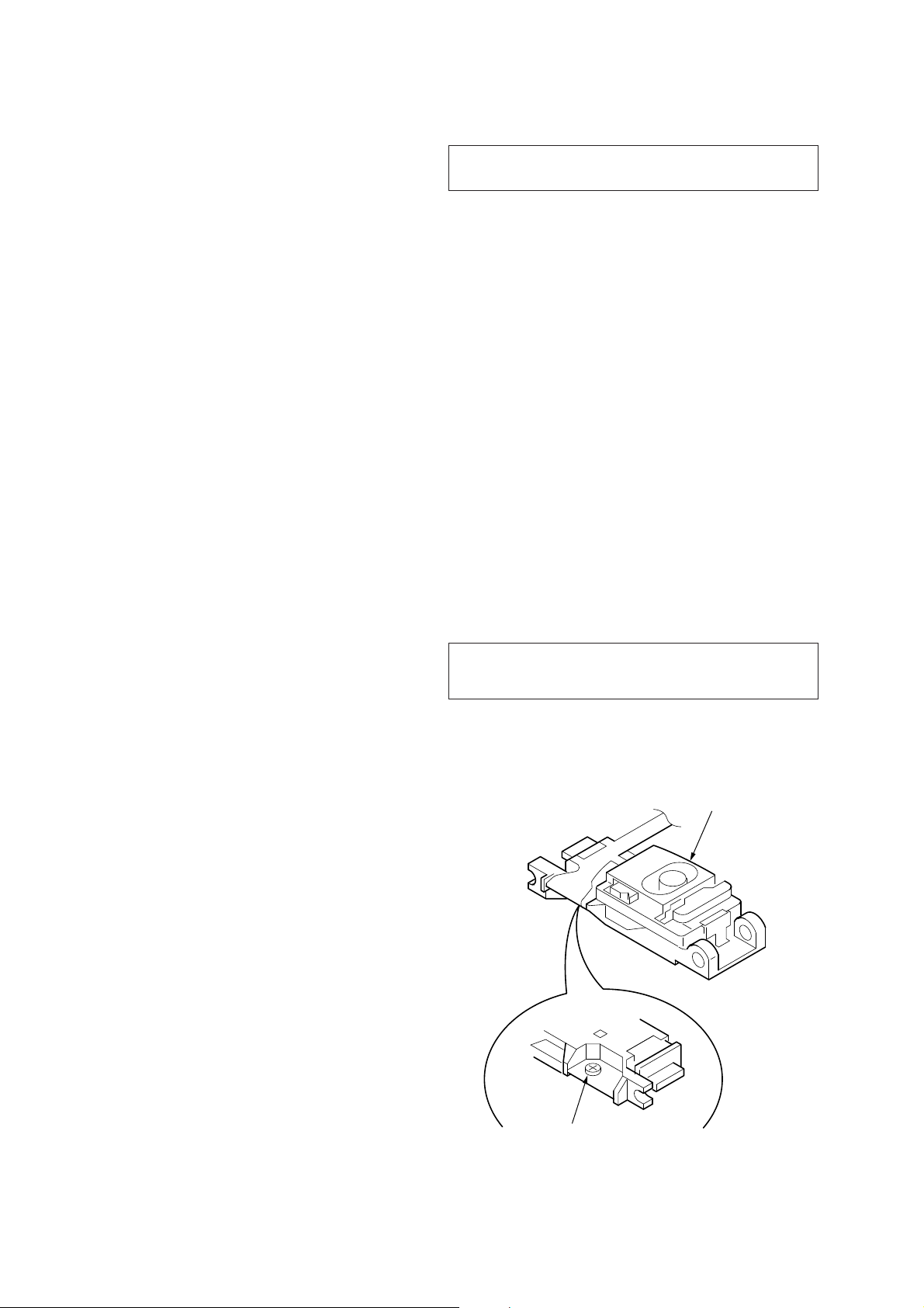
If the optical pick-up block is defective, please replace the whole
optical pick-up block.
Never turn the semi-fi xed resistor located at the side of optical
pick-up block.
optical pick-up
SAFETY-RELATED COMPONET WARNING!
COMPONENTS IDENTIFIED BY MARK 0 OR DOTTED LINE
WITH MARK 0 ON THE SCHEMATIC DIAGRAMS AND IN
THE PARTS LIST ARE CRITICAL TO SAFE OPERATION.
REPLACE THESE COMPONENTS WITH SONY PARTS
WHOSE PART NUMBERS APPEAR AS SHOWN IN THIS
MANUAL OR IN SUPPLEMENTS PUBLISHED BY SONY.
2
semi-fixed resistor

CDX-GT820IP
• CD playback
You can play CD-DA (also containing CD TEXT), CD-R/CDRW (MP3/WMA/AAC fi les).
Type of discs Label on the disc
CD-DA
MP3
WMA
AAC
UNLEADED SOLDER
Boards requiring use of unleaded solder are printed with the leadfree mark (LF) indicating the solder contains no lead.
(Caution: Some printed circuit boards may not come printed with
the lead free mark due to their particular size)
: LEAD FREE MARK
Unleaded solder has the following characteristics.
• Unleaded solder melts at a temperature about 40 °C higher
than ordinary solder.
Ordinary soldering irons can be used but the iron tip has to be
applied to the solder joint for a slightly longer time.
Soldering irons using a temperature regulator should be set to
about 350 °C.
Caution: The printed pattern (copper foil) may peel away if the
heated tip is applied for too long, so be careful!
• Strong viscosity
Unleaded solder is more viscous (sticky, less prone to fl ow)
than ordinary solder so use caution not to let solder bridges
occur such as on IC pins, etc.
• Usable with ordinary solder
It is best to use only unleaded solder but unleaded solder may
also be added to ordinary solder.
TABLE OF CONTENTS
1. SERVICE NOTE ..................................................... 4
2. GENERAL
Location of Controls ....................................................... 5
Connections .................................................................... 6
3. DISASSEMBLY
3-1. Sub Panel Assy ............................................................... 8
3-2. CD Mechanism Block ..................................................... 8
3-3. Main Board ..................................................................... 9
3-4. Servo Board .................................................................... 9
3-5. Chassis (T) Sub Assy ...................................................... 10
3-6. Roller Arm Assy .............................................................. 10
3-7. Chassis (OP) Assy ........................................................... 11
3-8. Chucking Arm Sub Assy ................................................. 11
3-9. Sled Motor Assy .............................................................. 12
3-10. Optical Pick-up Section .................................................. 13
3-11. Optical Pick-up ............................................................... 13
4. DIAGNOSIS FUNCTION ..................................... 14
5. DIAGRAMS
5-1. Block Diagram –Main Section– ..................................... 17
5-2. Block Diagram –Display Section– ................................. 18
5-3. Printed Wiring Board –Main Section (1/2)– ................... 20
5-4. Printed Wiring Board –Main Section (2/2)– ................... 21
5-5. Schematic Diagram –Main Section (1/4)– ...................... 22
5-6. Schematic Diagram –Main Section (2/4)– ...................... 23
5-7. Schematic Diagram –Main Section (3/4)– ...................... 24
5-8. Schematic Diagram –Main Section (4/4)– ...................... 25
5-9. Printed Wiring Board –Sub Section- .............................. 26
5-10. Schematic Diagram –Sub Section- ................................. 27
5-11. Printed Wiring Boards –Key Section – ........................... 28
5-12. Schematic Diagram –Key Section – ............................... 29
6. EXPLODED VIEWS
6-1. Main Section ................................................................... 36
6-2. Front Panel Section ......................................................... 37
6-3. CD Mechanism Section (MG-101I-188//Q) ................... 38
7. ELECTRICAL PARTS LIST .............................. 39
3
CDX-GT820IP
SECTION 1
SERVICE NOTE
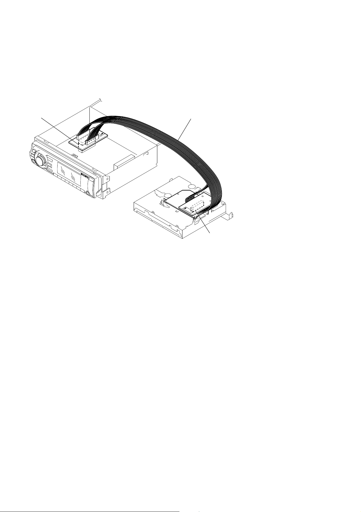
EXTENSION CABLE AND SERVICE POSITION
When repairing or servicing this set, connect the jig (extension
cable) as shown below.
• Connect the MAIN board (CN350) and the SERVO board
(CN401) with the extension cable (Part No. J-2502-076-1).
MAIN BOARD
CN350
NOTE FOR REPLACEMENT OF THE SERVO BOARD
When repairing, the complete SERVO board (A-1362-921-A)
should be replaced since any parts in the SERVO board cannot be
repaired.
J-2502-076-1
NOTE FOR THE 24-PIN CONNECTOR (CN901)
Do not use alcohol to clean the 24-pin connector (CN901) connecting the front panel with the main body.
Do not touch the connector directly with your bare hand. Poor contact may be caused.
SERVO BOARD
CN401
4
• Location of Controls
R
RER
R
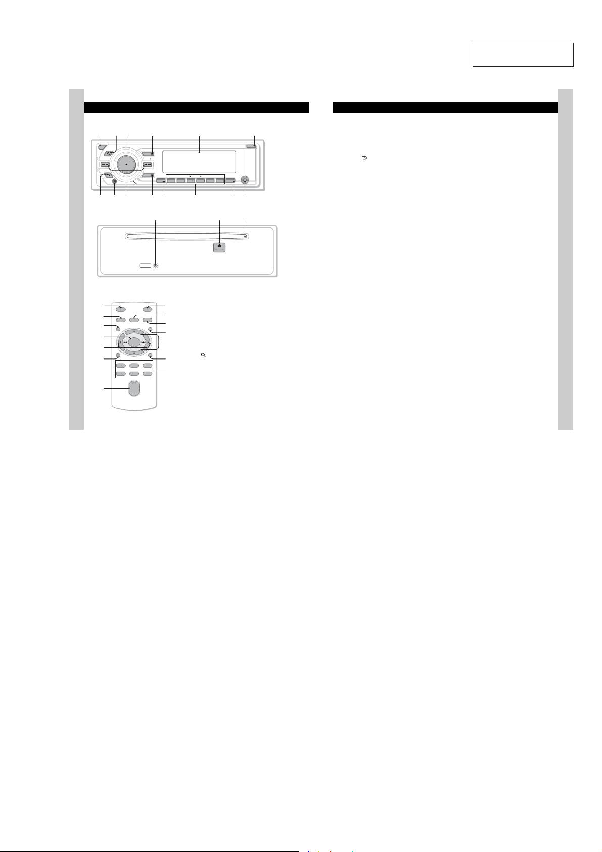
Location of controls and basic operations
Main unit
LIST/
OFF
BROWSE
SEEK SEEK
BACK
Front panel removed
Card remote commander
RM-X152
OFF
SOURCE SOUND
RL
MENU
RM
X
RE
XB
ENTER
DSPL
REP SHUF
132
465
+
–
+
VOL
–
8
SOURCE
MODE
PUSH ENTER/SOUND/MENU
RESET
ATT
MODE
LIST/
CAT
SCRL
PAUSE
SCRL
B
REP SHUF ALBUM
123456
T
This section contains instructions on the location
of controls and basic operation s. For details, see
the respective pages.
For iPod operation, see “iPod” on page 13, or for
XT
optional device (CD/MD changer, etc.)
operation, see “Using optional equipment” on
XE
page 17.
The corresponding buttons on the card remote
commander control the same functions as those
on the unit.
XG
" OFF button
XH
# (LIST/BROWSE) button page 10,
RB
RT
$ Control dial/select button
OPEN
AUX
PAUSE
DSPL
G
RI RKRH
To power off; stop the source.
13
To list up (Radio); enter the Quick-BrowZer
mode (CD/iPod).
Rotate to: Adj ust volume.
Press to: Enter sound setting/apply a menu
setting.
Press and hold to: Enter menu.
SECTION 2
GENERAL
% SOURCE button
To power on; change the source (Radio/CD /
1
iPod/AUX)*
& Display window
' OPEN button page 6, 7
( (BACK) button page 10
) Receptor for the card remote
* SEEK –/+ buttons
+ MODE button page 12, 13
, SCRL (scroll) button
- Number buttons
. DSPL (display) button page 12
/ AUX input jack page 17
0 RESET button page 4
1 ;(eject) button page 7
2 Disc slot page 7
.
Toreturnto the previous display.
commander
CD/iPod:
Toskip tracks (press); skip tracks
continuously (press, then press again within
about 1 second and hold); reverse/fastforward a track (press and hold).
Radio:
Totune in stations automatically (press); find
a station manually (press and hold).
To s elect the radi o b and (FM/ AM) *
the play mode of iPod.
Toscroll the display item.
CD/iPod:
: REP page 12, 14
: SHUF page 12, 14
/: ALBUM –/+
Toskip albums (press); skip albums
continuously (press and hold).
: PAUSE
Topause playback. Tocancel, press
again.
Radio:
To receive stored stations (press); store
stations (press and hold).
To change display items.
To connect a portab le audio device.
To e ject t he di s c.
To insert the disc.
CDX-GT820IP
This section is extracted
from instruction manual.
The following buttons on the card remote
commanderhave also differentbuttons/functions
from the unit. Remove the insulation film before
use (page 5).
S MENU button
To e nter menu.
RM ENTER button
Toapply a setting.
X ()/ ( ) buttons
Tocontrol CD/radio/iPod, thesame as
4&&, –/+ on the unit.
Setup, sound setting, etc., can be operated by
.
XB VOL (volume) +/– button
To a djust vo lume.
XT ATT (attenuate) button
Toattenuatethe sound. Tocancel, press
again.
XE SOUND button
1
;select
To enter sound setting.
Y LIST/CAT*
To list up (Radio); enter theQuick-BrowZer
mode (CD/iPod).
XH . (+)/N (–) buttons
Tocontrol CD/iPod, the same as /
(ALBUM –/+) on the unit.
Setup,soundsetting, etc., can be operated by
.N.
*1 In the case of a CD/MD changer, HD radio tuner or
SATtuner being connected; when 4063$& is
pressed, the connected device (“MD,” “HD,”“XM” or
“SR”) will appear in the display, depending on
which device is connected. Furthermore, if
.0%& is pressed, you can switch the changer,
HD radio tuner band or SAT tuner band.
*2 When the SAT tuner is connected.
Note
If the unit isturned off and the display disappears,it
cannot be operated with the card remote commander
unless4063$& on the unit is pressed, or a disc is
inserted to activate the unit first.
2
button
9
5
CDX-GT820IP
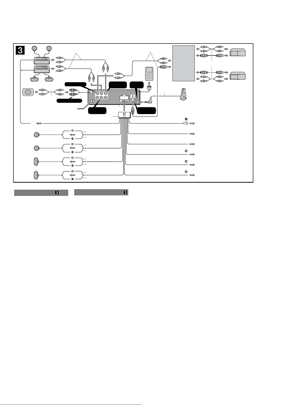
• Connections
2
1
*
*
Source selector
(not supplied)
Sélecteur de source
(non fourni)
XA-C40
Supplied with the CD/MD changer
Fourni avec le changeur de CD/MD
1
*
SUB OUT (MONO)
from car antenna (aerial)
à partir de l’antenne de la voiture
AMP REM
Max. supply current 0.3 A
Courant max. fourni 0,3 A
Left
Gauche
Right
Droit
Left
Gauche
Right
Droit
Connection diagram
To a metal surface of the car
First connect the black ground (earth) lead, then connect the
yellow and red power supply leads.
To the power antenna (aerial) control lead or
power supply lead of antenna (aerial) booster
Notes
• It is not necessary to connect this lead if there is no power
antenna (aerial) or antenna (aerial) booster, or with a
manually-operated telescopic antenna (aerial).
• When your car has a built-in FM/AM antenna (aerial) in
the rear/side glass, see “Notes on the control and power
supply leads.”
To AMP REMOTE IN of an optional power
amplifier
This connection is only for amplifiers. Connecting any other
system may damage the unit.
To the interface cable of a car telephone
To a car’s illumination signal
Be sure to connect the black ground (earth) lead to a metal
surface of the car first.
To the +12V power terminal which is
energized in the accessory position of the
ignition switch
Notes
• If there is no accessory position, connect to the +12 V
power (battery) terminal which is energized at all times.
Be sure to connect the black ground (earth) lead to a
metal surface of the car first.
• When your car has a built-in FM/AM antenna (aerial) in
the rear/side glass, see “Notes on the control and power
supply leads.”
To the +12V power terminal which is
energized at all times
Be sure to connect the black ground (earth) lead to a metal
surface of the car first.
Notes on the control and power supply leads
• The power antenna (aerial) control lead (blue) supplies +12 V
DC when you turn on the tuner.
• When your car has built-in FM/AM antenna (aerial) in the rear/
side glass, connect the power antenna (aerial) control lead
(blue) or the accessory power supply lead (red) to the power
terminal of the existing antenna (aerial) booster.For details,
consult your dealer.
• A power antenna (aerial) without a relay box cannot be used
with this unit.
Memory hold connection
When the yellow power supply lead is connected, power will
always be supplied to the memory circuit even when the ignition
switch is turned off.
Notes on speaker connection
• Before connecting the speakers, turn the unit off.
• Use speakers with an impedance of 4 to 8 ohms, and with
adequate power handling capacities to avoid its damage.
• Do not connect the speaker terminals to the car chassis, or
connect the terminals of the right speakers with those of the
left speaker.
• Do not connect the ground (earth) lead of this unit to the
negative (–) terminal of the speaker.
• Do not attempt to connect the speakers in parallel.
• Connect only passive speakers. Connecting active speakers
(with built-in amplifiers) to the speaker terminals may damage
the unit.
• To avoid a malfunction, do not use the built-in speaker leads
installed in your car if the unit shares a common negative (–)
lead for the right and left speakers.
• Do not connect the unit’s speaker leads to each other.
Notes on connection
• If speakerand amplifier are not connected correctly,“FAILURE”
appears in the display. In this case, make sure the speaker and
amplifier are connected correctly.
• An another iPod cannot be connected using the interface
adapter for iPod XA-110IP/XA-120IP.
BUS AUDIO IN
L
R
REAR
FRONT
BUS
AUDIO
OUT
IN
REAR
AUDIO OUT
Blue/white striped
Rayé bleu/blanc
White
Blanc
White/black striped
Rayé blanc/noir
Gray
Gris
Gray/black striped
Rayé gris/noir
Green
Vert
Green/black striped
Rayé vert/noir
Purple
Mauve
Purple/black striped
Rayé mauve/noir
Fuse (10 A)
Fusible (10 A)
Schéma de raccordement
Vers un point métallique de la voiture
Branchez d’abord le câble de mise à la masse noir et,
ensuite, les câbles d’alimentation jaune et rouge.
Vers le câble de commande d’antenne
électrique ou vers le câble d’alimentation de
l’amplificateur d’antenne
Remarques
• Il n’est pas nécessaire de raccorder ce câble s’il n’y a pas
d’antenne électrique ni d’amplificateur d’antenne, ou avec
une antenne télescopique manuelle.
• Si votrevoiture est équipée d’une antenne FM/AM
intégrée dans la vitre arrière/latérale, voir « Remarques
sur les câbles de commande et d’alimentation ».
Vers AMP REMOTE IN de l’amplificateur de
puissance en option
Ce raccordement s’applique uniquement aux amplificateurs.
Le branchement de tout autre système risque
d’endommager l’appareil.
Vers le cordon de liaison d’un téléphone de
voiture
Vers le connecteur du signal d’éclairage de
la voiture
Raccordez d’abord le câble de mise à la masse noir à un
point métallique du véhicule.
Vers la borne d’alimentation +12V qui est
alimentée quand la clé de contact est sur la
position accessoires
Remarques
• S’il n’y a pas de position accessoires, raccordez la borne
d’alimentation (batterie) +12 V qui est alimentée en
permanence.
Raccordez d’abord le câble de mise à la masse noir à un
point métallique du véhicule.
• Si votrevoiture est équipée d’une antenne FM/AM
intégrée dans la vitre arrière/latérale, voir « Remarques
sur les câbles de commande et d’alimentation ».
Vers la borne d’alimentation +12V qui est
alimentée en permanence
Raccordez d’abord le câble de mise à la masse noir à un
point métallique du véhicule.
Remarques sur les câbles de commande et d’alimentation
• Le câble de commande d’antenne électrique (bleu) fournit une
alimentation de + 12 V CC lorsque vous mettez la radio sous
tension.
• Lorsque votrevoiture est équipée d’une antenne FM/
AM intégrée dans la vitre arrière/latérale, raccordez le
câble de commande d’antenne électrique (bleu) ou le
câble d’alimentation des accessoires (rouge) à la borne
d’alimentation de l’amplificateur d’antenne existant.Pour plus
de détails, consultez votre détaillant.
• Une antenne électrique sans boîtier de relais ne peut pas être
utilisée avec cet appareil.
Raccordement pour la conservation de la mémoire
Lorsque le câble d’alimentation jaune est raccordé, le circuit
de la mémoire est alimenté en permanence même si la clé de
contact est sur la position d’arrêt.
Remarques sur le raccordement des haut-parleurs
• Avant de raccorder les haut-parleurs, mettez l’appareil hors
tension.
• Utilisez des haut-parleurs ayant une impédance de 4 à 8 ohms
avec une capacité électrique adéquate pour éviter de les
endommager.
• Ne raccordez pas les bornes du système de haut-parleurs au
châssis de la voiture et ne raccordez pas les bornes du hautparleur droit à celles du haut-parleur gauche.
• Ne raccordez pas le câble de mise à la masse de cet appareil
à la borne négative (–) du haut-parleur.
• N’essayez pas de raccorder les haut-parleurs en parallèle.
• Raccordez uniquement des haut-parleurs passifs. Le
raccordement de haut-parleurs actifs (avec amplificateurs
intégrés) aux bornes des haut-parleurs peut endommager
l’appareil.
• Pour éviter tout problème de fonctionnement, n’utilisez pas les
câbles des haut-parleurs intégrés installés dans votre voiture si
l’appareil possède un câble négatif commun (–) pour les hautparleurs droit et gauche.
• Ne raccordez pas entre eux les cordons des haut-parleurs de
l’appareil.
Remarques sur le raccordement
• Si les haut-parleurs et l’amplificateur ne sont pas raccordés
correctement, le message « FAILURE » s’affiche. Dans ce cas,
assurez-vous que les haut-parleurs et l’amplificateur sont bien
raccordés.
• Il est impossible de raccorder un autre iPod à l’aide de
l’adaptateur d’interface pour iPod XA-110IP/XA120IP.
FRONT
AUDIO OUT
REMOTE
IN
CONTROL IN
Black
Noir
Blue
Bleu
Light blue
Bleu ciel
Orange/white striped
Rayé orange/blanc
Red
Rouge
Yellow
Jaune
BUS
3
*
Max. supply current 0.1 A
Courant max. fourni 0,1 A
ANT REM
ATT
ILLUMINATION
1
RCA pin cord (not supplied)
*
2
*
Supplied with XA-C40
3
*
Insert with the cord upwards.
1
Cordon à broche RCA (non
*
fourni)
2
*
Fourni avec le XA-C40
3
*
Insérez avec le câble vers le bas.
6
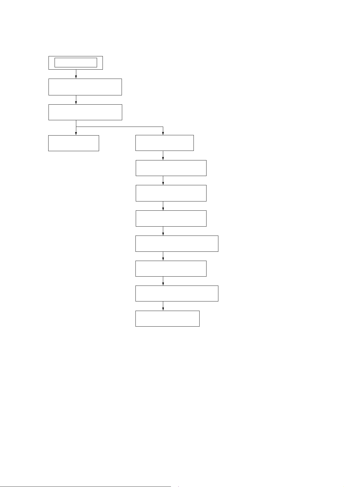
DISASSEMBLY
• This set can be disassembled in the order shown below.
SET
3-1. SUB PANEL ASSY
(Page 8)
3-2. CD MECHANISM BLOCK
(Page 8)
CDX-GT820IP
SECTION 3
3-3. MAIN BOARD
(Page 9)
3-4. SERVO BOARD
(Page 9)
3-5. CHASSIS (T) SUB ASSY
(Page 10)
3-6. ROLLER ARM ASSY
(Page 10)
3-7. CHASSIS (OP) ASSY
(Page 11)
3-8. CHUCKING ARM SUB ASSY
(Page 11)
3-9. SLED MOTOR ASSY
(Page 12)
3-10. OPTICAL PICK-UP SECTION
(Page 13)
3-11. OPTICAL PICK-UP
(Page 13)
7
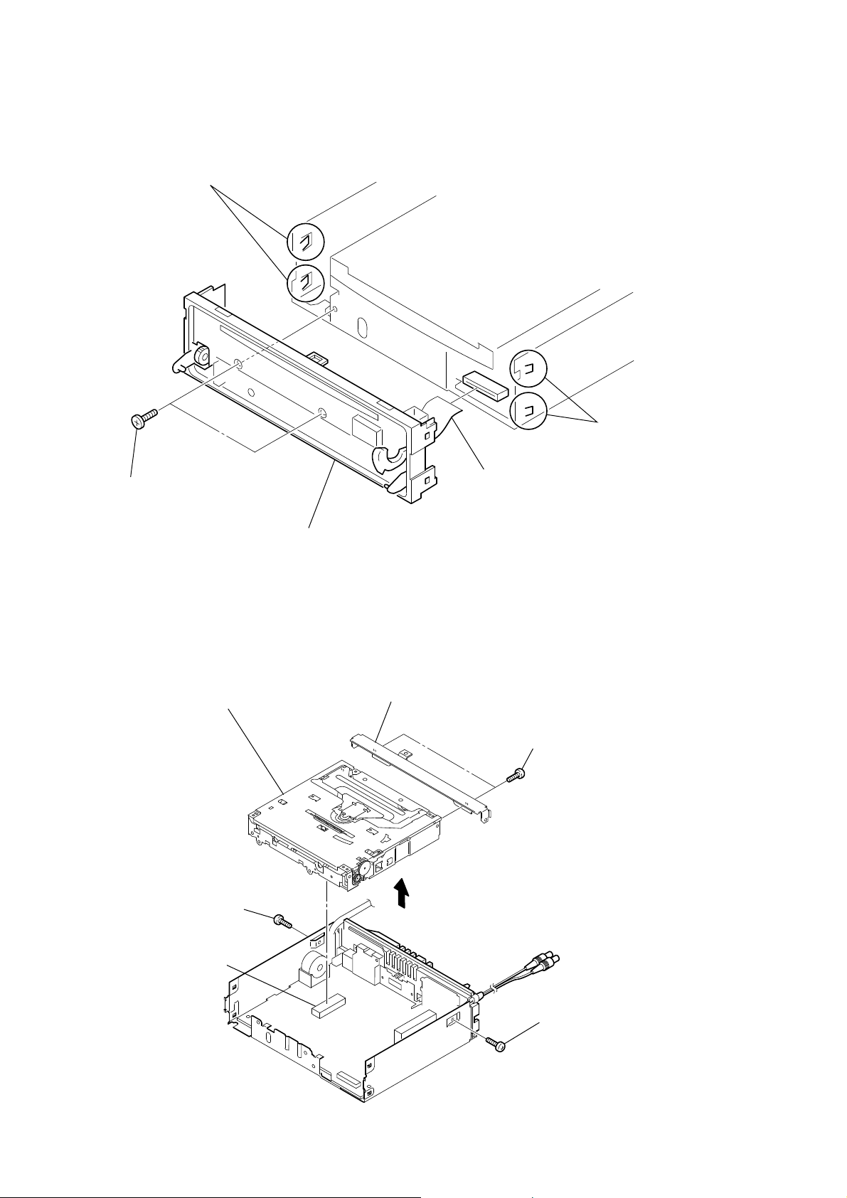
CDX-GT820IP
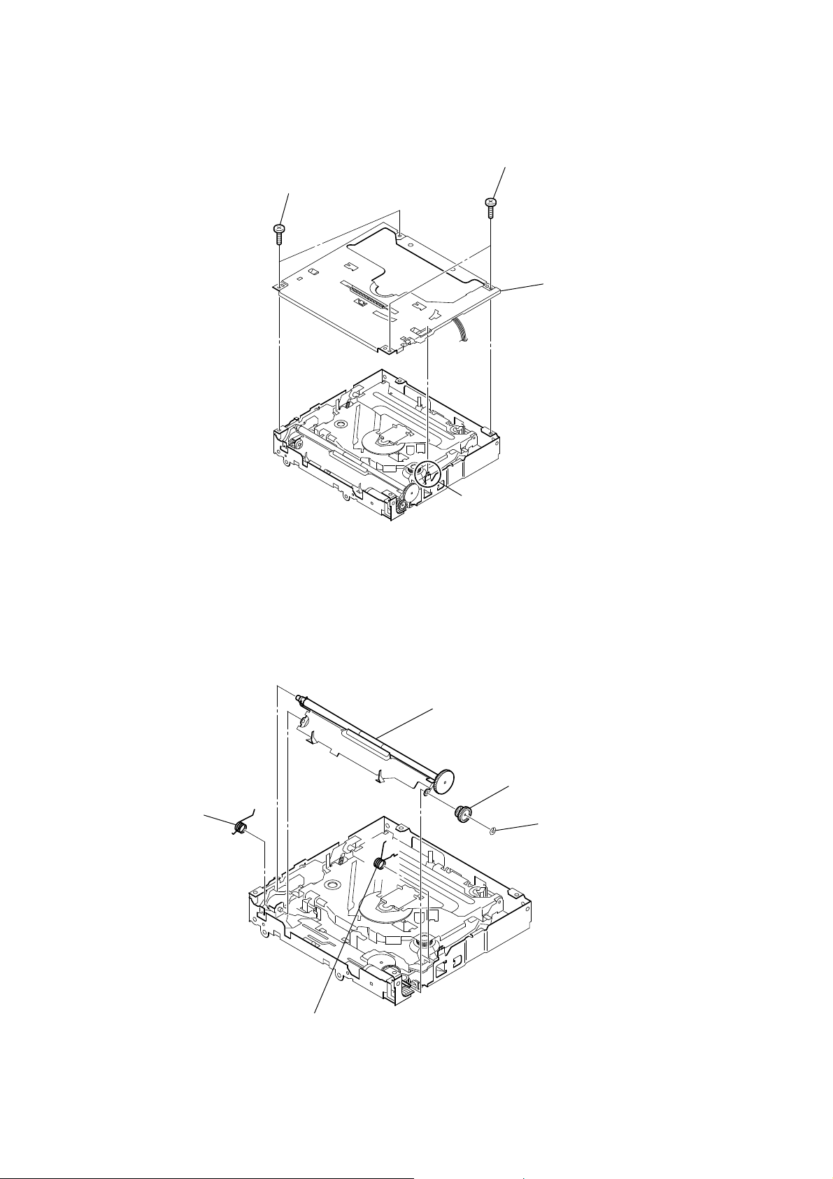
Note: Follow the disassembly procedure in the numerical order shown below.
3-1. SUB PANEL ASSY
two claws
two claws
two screws
(+PTT 2.6 × 6)
3-2. CD MECHANISM BLOCK
CD mechanism block
screw
(+PTT 2.6 × 6)
flexible flat cable (23 core)
(CN370)
sub panel assy
bracket (CD)
two screws
(+PTT 2.6 × 4)
CN350
screw
(+PTT 2.6 × 6)
8
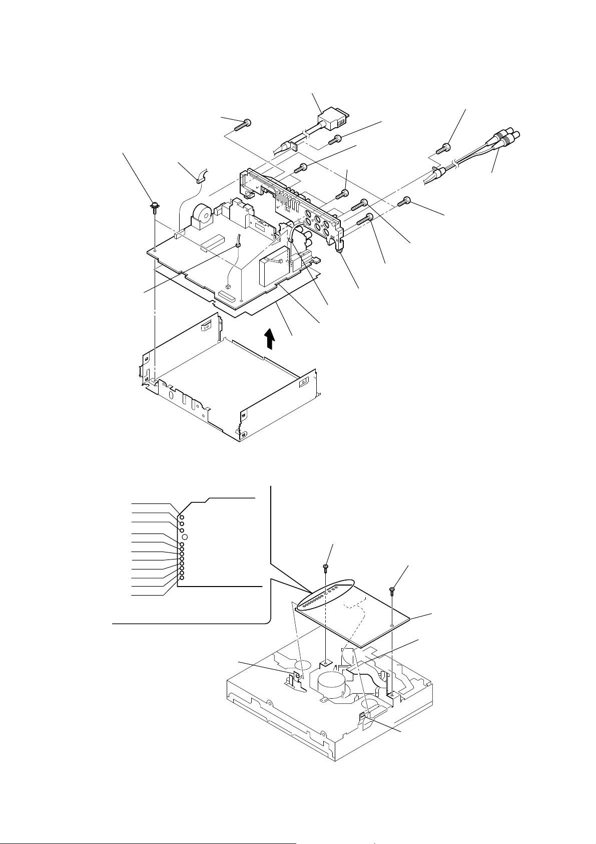
3-3. MAIN BOARD
RBscrew
(+PTT 2.6 × 10)
three ground point screws
(+PTT 2.6 × 6)
CN250 (8P)
CN200 (3P)
insulating sheet
automobile cord (for iPod)
screw
(+PTT 2.6 × 8)
RTtwo screws
(+P 2.6 × 8)
REtwo screws
(+PTT 2.6 × 10)
RHscrew
(+PTT 2.6 × 10)
RIheat sink
CN410 (3P)
RKMAIN board
CDX-GT820IP
screw
(+PTT 2.6 × 8)
connection
cord (RCA)
two screws
(+PTT 2.6 × 8)
RGtwo screws
(+P 2.6 × 10)
3-4. SERVO BOARD
WHT
RED
BLK
WHT
RED
BLK
RED
ORG
BLU
YEL
GRY
Remove the eleven solders.
SERVO board
claw
toothed lock screw
(M 1.7 × 2.5)
toothed lock screw
(M 1.7 × 2.5)
SERVO board
optical pick-up (16 core)
(CN111)
claw
9
CDX-GT820IP
3-5. CHASSIS (T) SUB ASSY
two precision screws
(+P 1.7 × 2.2)
two precision screws
(+P 1.7 × 2.2)
chassis (T) sub assy
claw
3-6. ROLLER ARM ASSY
spring (RAL)
roller arm assy
gear (RA1)
washer
spring (RAR)
10
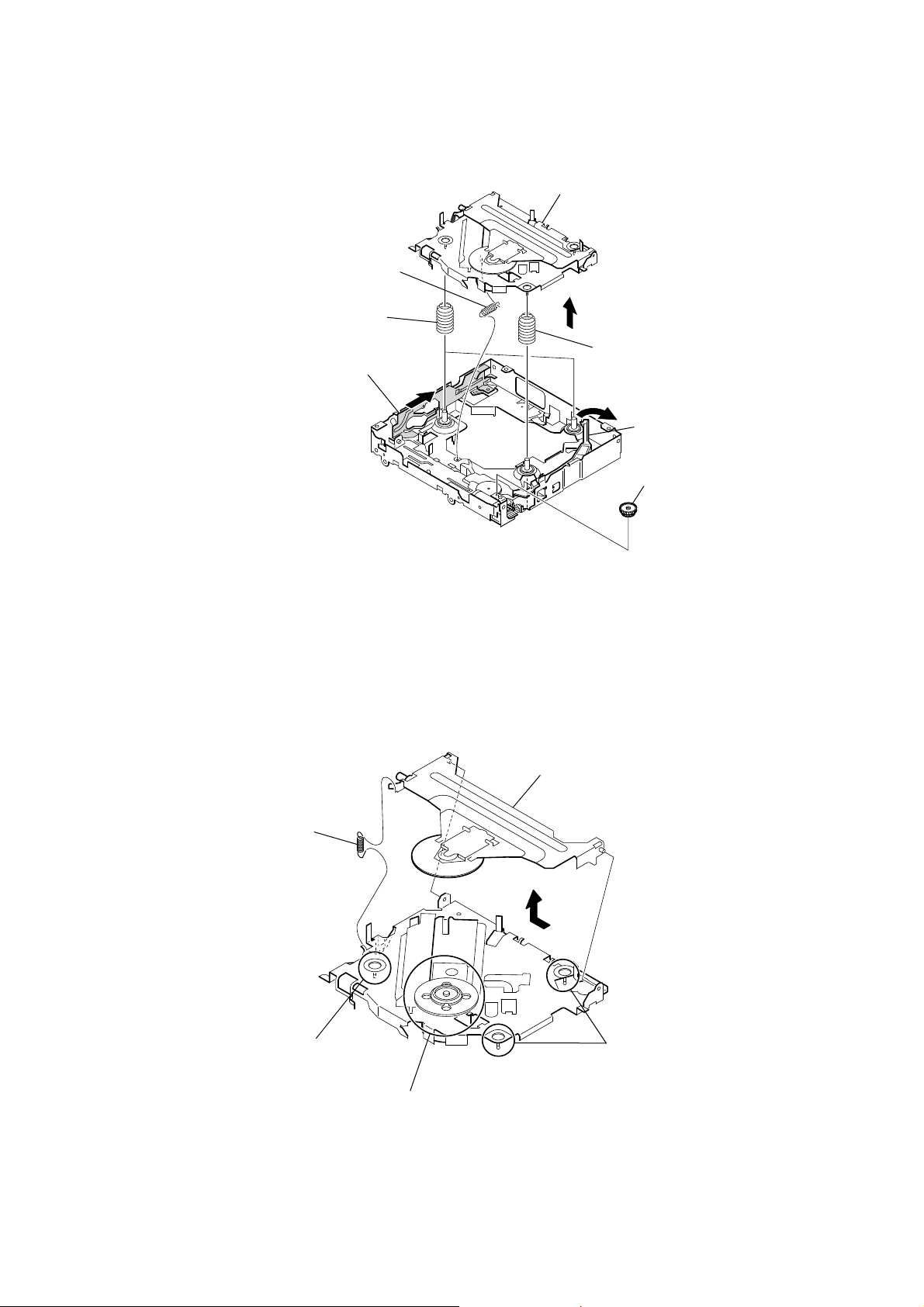
3-7. CHASSIS (OP) ASSY
coil spring (damper) (natural)
CDX-GT820IP
chassis (OP) assy
tension spring (KF)
coil spring (damper) (green)
slider (R)
lever (D)
gear (LE1)
3-8. CHUCKING ARM SUB ASSY
spring
Note: Have this portion receive the chassis.
chucking arm sub assy
Note: Have this portion receive the chassis.
Note: Be careful not to touch the turn table.
11
CDX-GT820IP
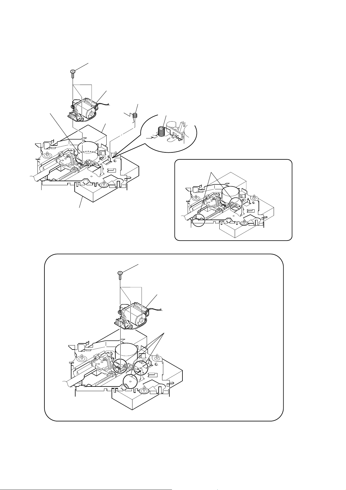
3-9. SLED MOTOR ASSY
turn table
three serration screws
(M 2 × 3)
sled mtor assy
spring
spring
stand
Note:
Never remove these parts since they were adjusted.
stand
Note: Place the stand with care not to touch the turn table.
Note for Assembly
three serration screws
(M 2 × 3)
sled mtor assy
Note: Take care to prevent the chassis from being bent
when tightening the three machine screws.
12
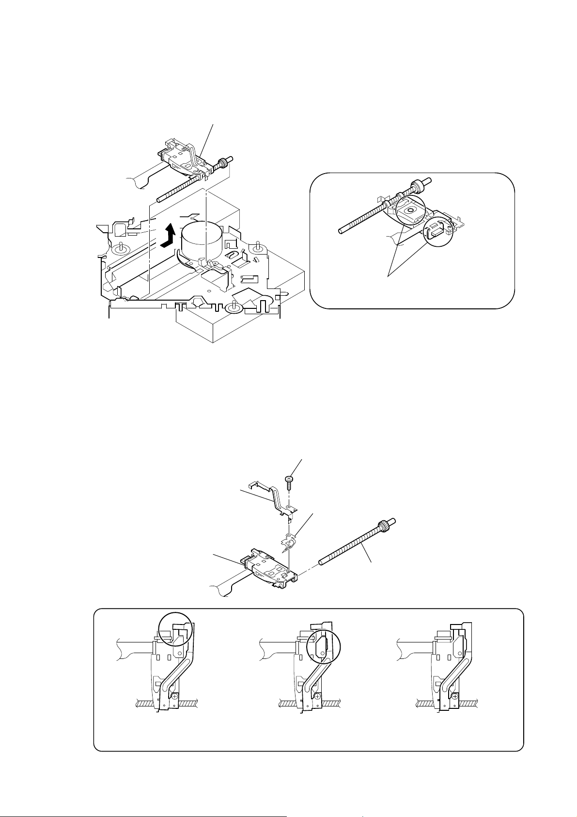
3-10. OPTICAL PICK-UP SECTION
optical pick-up section
CDX-GT820IP
Note: Be careful not to touch the lens and hologram
terminal when removing the optical pick-up section.
3-11. OPTICAL PICK-UP
leaf spring (sub guide)
optical pick-up
Notes for Assembly
pan tapping screw
(M 1.4 × 2.5)
leaf spring (OP)
lead screw assy
Prevent the end of the
leaf spring (sub guide) from being
in contact with the OP slide base.
Prevent the end of the
leaf spring (sub guide) from being
in contact with the OP slide base.
There is space at the end of the
leaf spring (sub guide) to avoid
contact with the slide.
13
CDX-GT820IP
SECTION 4
DIAGNOSIS FUNCTION
Description of the Diagnostics function:
1. Setting the Diag display mode
With the power off, press the [4/ALBUM +] button, [5] button,
and [4/ALBUM +] button on the set body or the remote control
(for more than 2 seconds) in turn.
2. Canceling the Diag display mode
During the Diag function mode, press the [OFF] button.
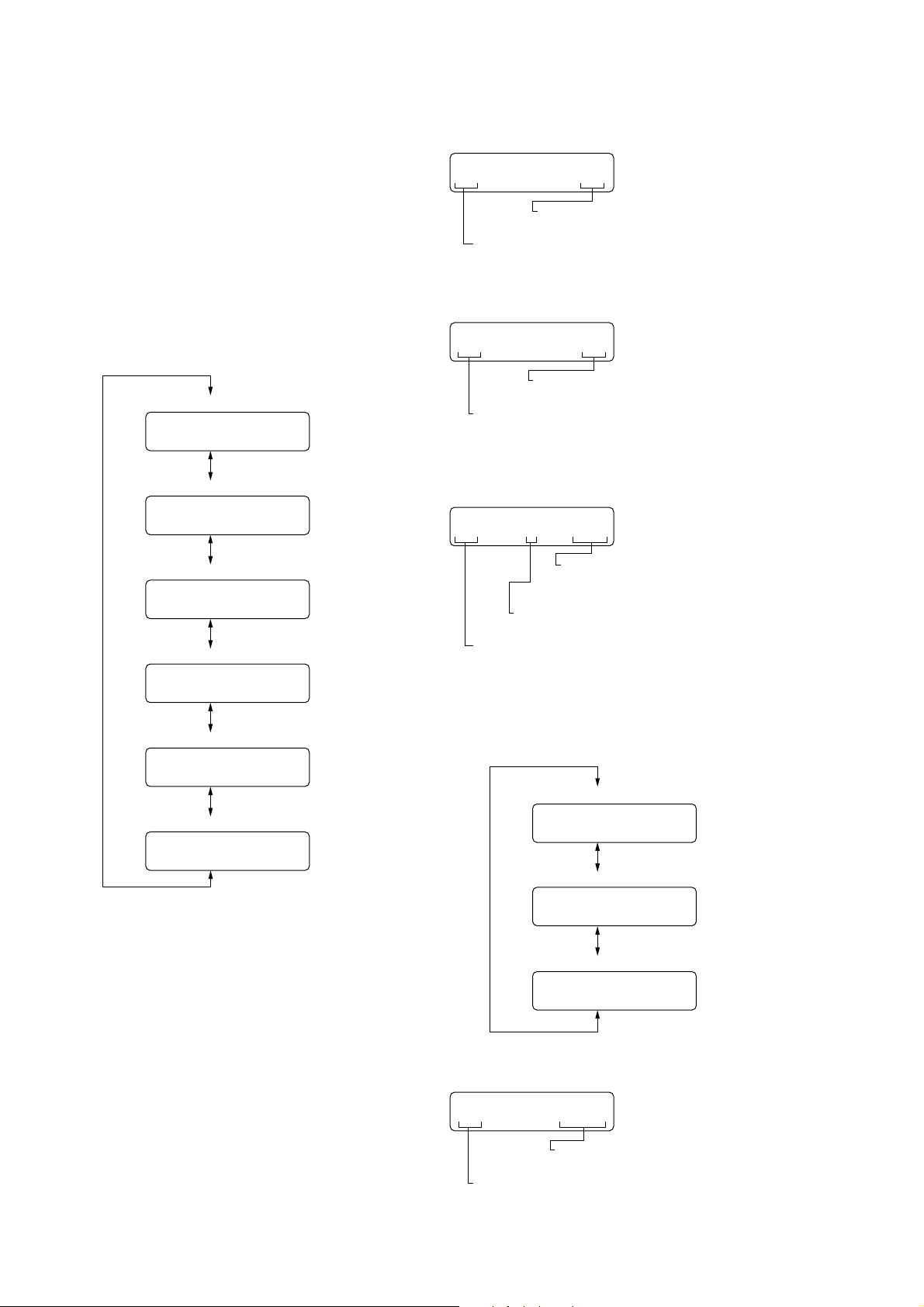
3. Initial display in the Diag display mode.
Just when the Diag mode is entered, “reset count” is displayed.
The display mode is switched by each rotation of [
SEEK+] or [
. m/
Reset count display
Reset count by watchdog timer display
Number of connected units display
Operating hours display
01
02
03
SEEK–] keys.
1
XX
XX
XXX
M >/
4. Contents of each display mode
4-1. Reset count display mode
01
Diag code
01: Reset count
4-2. Reset count by watchdog timer display mode
XX
Reset count
(in hexadecimal format)
02 XX
Reset count
(in hexadecimal format)
Diag cord
02: Number of resets by watchdog timer
4-3. Number of connected units display mode
03
Diag code
03: Number of connected unit
1
Recency of information
1 - 3: 1 represents the latest.
XXX
Show the number of connected units for
CD-C, MD-C and XM respectively from
the rightmost (in hexadecimal format).
04
CD error information display
05
OFFSET/FAILURE error display
06
1
1
XXXX
XX
XXXXX
The display mode is switched by each rotation of [4/ALBUM +] or
[3/ALBUM –] keys during the number of connected units display
mode.
No. of connected units history 1 (latest) display
03
No. of connected units history 2 display
03
No. of connected units history 3 display
03
4-4. Operating hours display mode
04
XXXX
1
2
3
XXX
XXX
XXX
14
Operating hours
(in hexadecimal format)
Diag code
04: Operating hours
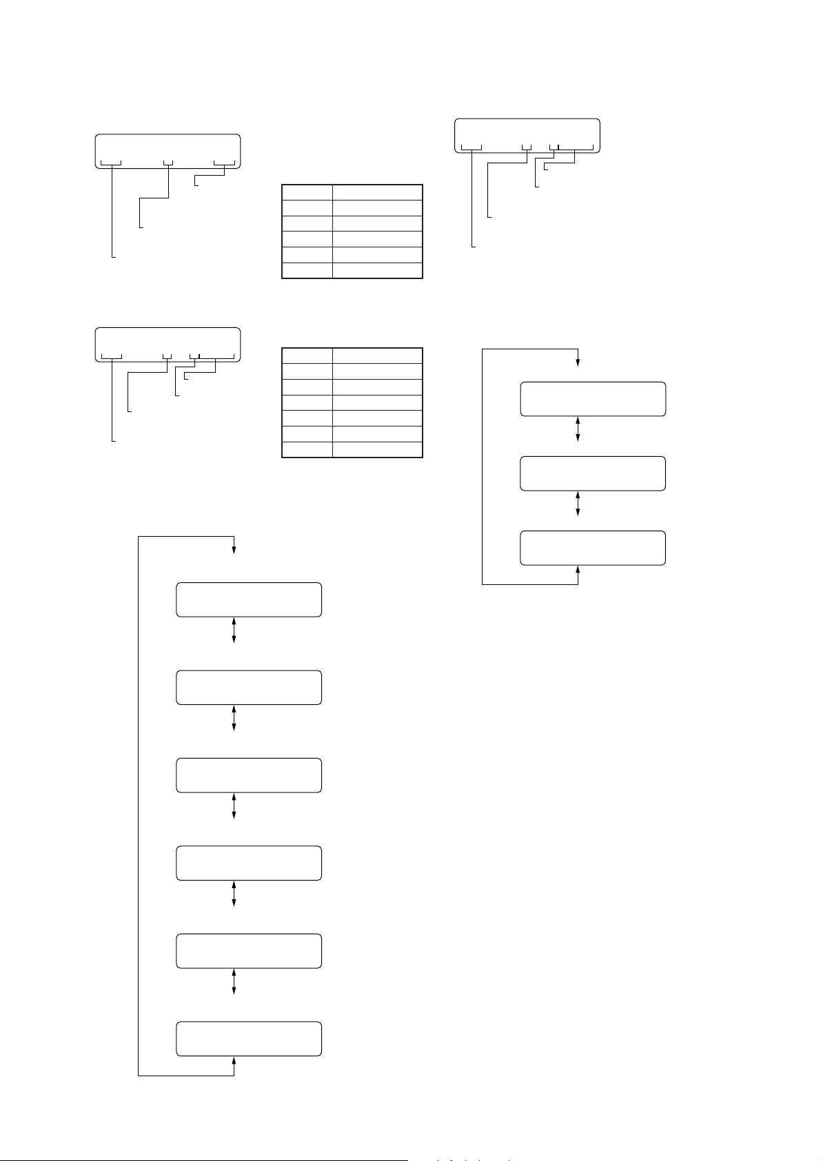
CDX-GT820IP
4-5. CD error information display mode
4-5-1. Error description
05
Diag code
05: CD error information
4-5-2. Operating hours
05
Diag code
05: CD error information
The display mode is switched by each rotation of [4/ALBUM +]
or [3/ALBUM –] keys during the CD error information display
mode.
1
Recency of information
1 - 3: 1 represents the latest.
1 XXXXX
Recency of information
1 - 3: 1 represents the latest.
XX
Error description
(in hexadecimal
format)
Operating hours
Disc type
Error information
Indication
1X
3X
4X
5X
FX
Disc type
Indication
0
1
2
3
8
F
Description
SERVO ERROR
LOADING ERROR
TRACK JUMP
TEXT ERROR
MECHA ERROR
Disc type
MP3
WMA
AAC
ATRAC
CD-DA
UNKNOWN
4-6. OFFSET/FAILURE error display mode
06
Diag code
06: OFFSET/FAILURE
The display mode is switched by each rotation of [4/ALBUM +] or
[3/ALBUM –] keys during the OFFSET/F
mode.
1 XXXXX
Operating hours
Error description
(0: OFFSET, 1: FAILURE)
Recency of information
1 - 3: 1 represents the latest.
AILURE error display
OFFSET/FAILURE error history 1 (latest) display
XXXXX
06
OFFSET/FAILURE error history 2 display
06
OFFSET/FAILURE error history 3 display
1
2
XXXXX
CD error info history 1 (latest)
Error description plus error details display
05
CD error info history 1 (latest)
Disc type plus operating hours display
05
CD error info history 2
Error description plus error details display
05
CD error info history 2
Disc type plus operating hours display
05
CD error info history 3
Error description plus error details display
1
1
2
2
XX
XXXXX
XX
XXXXX
06
3
XXXXX
05
CD error info history 3
Disc type plus operating hours display
05
3
3
XX
XXXXX
15
 Loading...