

Page 1

©2008 Sony Corporation Printed in Thailand
4-109-734-31(1)
FRONT
AUDIO OUT
REAR / SUB
AUDIO OUT
L
R
REAR/SUB FRONT
AUDIO OUT
3
1
2
4
5
REMOTE
IN
FRONT
AUDIO OUT
REAR / SUB
AUDIO OUT
*
2
Equipment used in illustrations (not supplied)
Front speaker
Power amplifier
1
*
FM/AM
Compact Disc Player
Rear speaker
Active subwoofer
Rotary commander RM-X4S
Left
Right
from car antenna (aerial)
AMP REM
Max. supply current 0.3 A
1
*
3
*
Fuse (10 A)
Blue/white striped
White
White/black striped
Gray
Gray/black striped
Black
Blue
ANT REM
Max. supply current 0.1 A
*1 RCA pin cord (not supplied)
*2 AUDIO OUT can be switched SUB or
REAR. For details, see the supplied
Operating Instructions.
*3 Insert with the cord upwards.
Installation/Connections
CDX-GT480US
CDX-GT480U
Green
Left
Green/black striped
Purple
Right
Purple/black striped
Cautions
• This unit is designed for negative ground (earth) 12 V
DC operation only.
• Do not get the leads under a screw, or caught in moving
parts (e.g. seat railing).
• Before making connections, turn the car ignition off to
× 2
avoid short circuits.
• Connect the yellow
after all other leads have been connected.
• Run all ground (earth) leads to a common
ground (earth) point.
• Be sure to insulate any loose unconnected leads with
electrical tape for safety.
Notes on the power supply lead (yellow)
• When connecting this unit in combination with other
stereo components, the connected car circuit’s rating
must be higher than the sum of each component’s fuse.
• When no car circuits are rated high enough, connect
the unit directly to the battery.
and red power input leads only
Parts list
• The numbers in the list are keyed to those in the
× 4
instructions.
• The bracket
attached to the unit before shipping. Before mounting
the unit, use the release keys
from the unit. For details, see “Removing the
protection collar and the bracket (
side of the sheet.
• Keep the release keys for future use as they
are also necessary if you remove the unit from
your car.
Caution
Handle the bracket
fingers.
and the protection collar are
to remove the bracket
)” on the reverse
carefully to avoid injuring your
Catch
Note
Before installing, make sure that the catches on both sides of
the bracket
straight or bent outwards, the unit will not be installed securely
and may spring out.
are bent inwards 2 mm (3/32 in). If the catches are
Connection example
Notes
• Be sure to connect the ground (earth) lead before connecting
the amplifier.
• The alarm will only sound if the built-in amplifier is used.
Connection diagram
To a metal surface of the car
First connect the black ground (earth) lead, then connect the
yellow, and red power supply leads.
To the power antenna (aerial) control lead or
power supply lead of antenna (aerial) booster
amplifier
Notes
• It is not necessary to connect this lead if there is no power
antenna (aerial) or antenna (aerial) booster, or with a
manually-operated telescopic antenna (aerial).
• When your car has a built-in FM/AM antenna (aerial) in
the rear/side glass, see “Notes on the control and power
supply leads.”
To AMP REMOTE IN of an optional power
amplifier
This connection is only for amplifiers. Connecting any other
system may damage the unit.
To the +12 V power terminal which is
energized in the accessory position of the
ignition key switch
Notes
• If there is no accessory position, connect to the +12 V
power (battery) terminal which is energized at all times.
Be sure to connect the black ground (earth) lead to a
metal surface of the car first.
• When your car has a built-in FM/AM antenna (aerial) in
the rear/side glass, see “Notes on the control and power
supply leads.”
To the +12 V power terminal which is
energized at all times
Be sure to connect the black ground (earth) lead to a metal
surface of the car first.
Notes on the control and power supply leads
• The power antenna (aerial) control lead (blue) supplies +12 V
DC when you turn on the tuner.
• When your car has built-in FM/AM antenna (aerial) in the rear/
side glass, connect the power antenna (aerial) control lead
(blue) or the accessory power supply lead (red) to the power
terminal of the existing antenna (aerial) booster. For details,
consult your dealer.
• A power antenna (aerial) without a relay box cannot be used
with this unit.
Memory hold connection
When the yellow power supply lead is connected, power will
always be supplied to the memory circuit even when the ignition
switch is turned off.
Notes on speaker connection
• Before connecting the speakers, turn the unit off.
• Use speakers with an impedance of 4 to 8 ohms, and with
adequate power handling capacities to avoid its damage.
• Do not connect the speaker terminals to the car chassis, or
connect the terminals of the right speakers with those of the
left speaker.
• Do not connect the ground (earth) lead of this unit to the
negative (–) terminal of the speaker.
• Do not attempt to connect the speakers in parallel.
• Connect only passive speakers. Connecting active speakers
(with built-in amplifiers) to the speaker terminals may damage
the unit.
• To avoid a malfunction, do not use the built-in speaker leads
installed in your car if the unit shares a common negative (–)
lead for the right and left speakers.
• Do not connect the unit’s speaker leads to each other.
Note on connection
If speaker and amplifier are not connected correctly, “FAILURE”
appears in the display. In this case, make sure the speaker and
amplifier are connected correctly.
Red
Yellow
Page 2
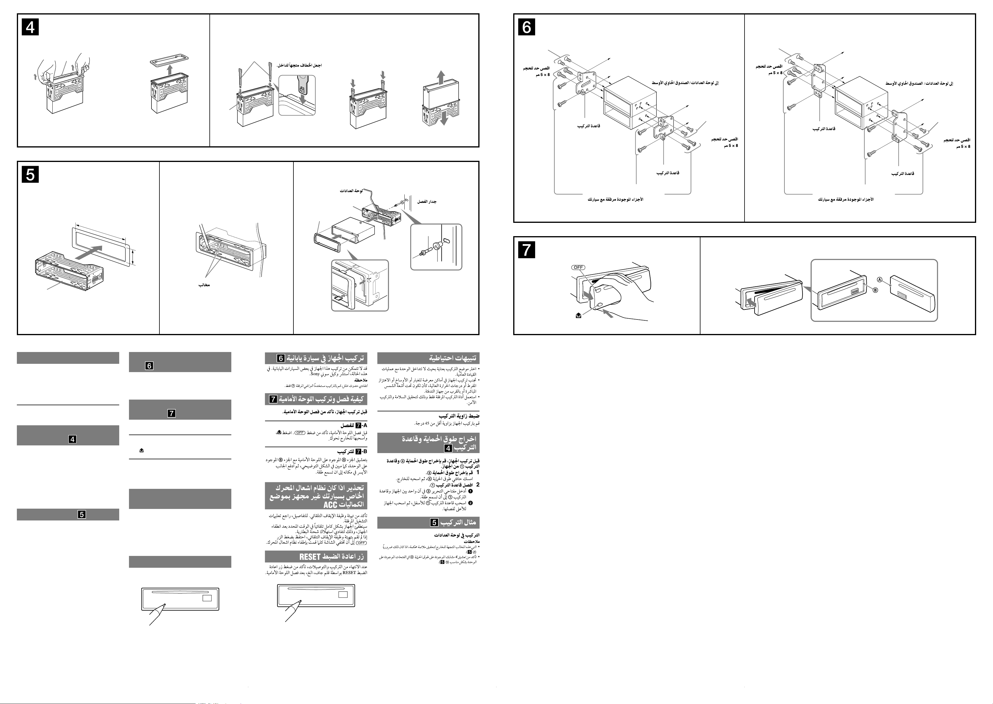
182 mm
53
m
m
1
2
A TOYOTA B NISSAN
1
Face the hook inwards.
2 3
Dashboard
Fire wall
max. size
5 × 8 mm
(7/32 × 11/32 in)
to dashboard/center console
Bracket
Bracket
Existing parts supplied with your car
max. size
5 × 8 mm
(7/32 × 11/32 in)
max. size
5 × 8 mm
(7/32 × 11/32 in)
Bracket
Existing parts supplied with your car
to dashboard/center console
Bracket
max. size
5 × 8 mm
(7/32 × 11/32 in)
Precautions
• Choose the installation location carefully so that the
unit will not interfere with normal driving operations.
• Avoid installing the unit in areas subject to dust, dirt,
excessive vibration, or high temperatures, such as in
direct sunlight or near heater ducts.
• Use only the supplied mounting hardware for a safe
and secure installation.
Mounting angle adjustment
Adjust the mounting angle to less than 45°.
Claws
Mounting the unit in a Japanese
car
You may not be able to install this unit in some makes of
Japanese cars. In such a case, consult your Sony dealer.
Note
To prevent malfunction, install only with the supplied screws
.
How to detach and attach the
front panel
A
B
Removing the protection collar
and the bracket
Before installing the unit, remove the protection
collar and the bracket from the unit.
1 Remove the protection collar .
Pinch both edges of the protection collar , then
pull it out.
2 Remove the bracket .
Insert both release keys together between
the unit and the bracket until they click.
Pull down the bracket , then pull up the unit
to separate
Mounting example
Installation in the dashboard
Notes
• Bend these claws outward for a tight fit, if necessary (-2).
• Make sure that the 4 catches on the protection collar are
properly engaged in the slots of the unit
(-3).
Before installing the unit, detach the front panel.
-A To detach
Before detaching the front panel, be sure to press .
Press , and pull it off towards you.
-B To attach
Engage part of the front panel with part of the unit,
as illustrated, and push the left side into position until it
clicks.
Warning if your car’s ignition
has no ACC position
Be sure to set the Auto Off function. For details, see the
supplied Operating Instructions.
The unit will shut off completely and automatically in
the set time after the unit is turned off, which prevents
battery drain.
If you do not set the Auto Off function, press and hold
until the display disappears each time you turn
the ignition off.
RESET button
When the installation and connections are completed,
be sure to press the RESET button with a ball-point pen,
etc., after detaching the front panel.
 Loading...