

Sony CDX-2250, CDX-3500 Service manual
CDX-2250/3500
SERVICE MANUAL
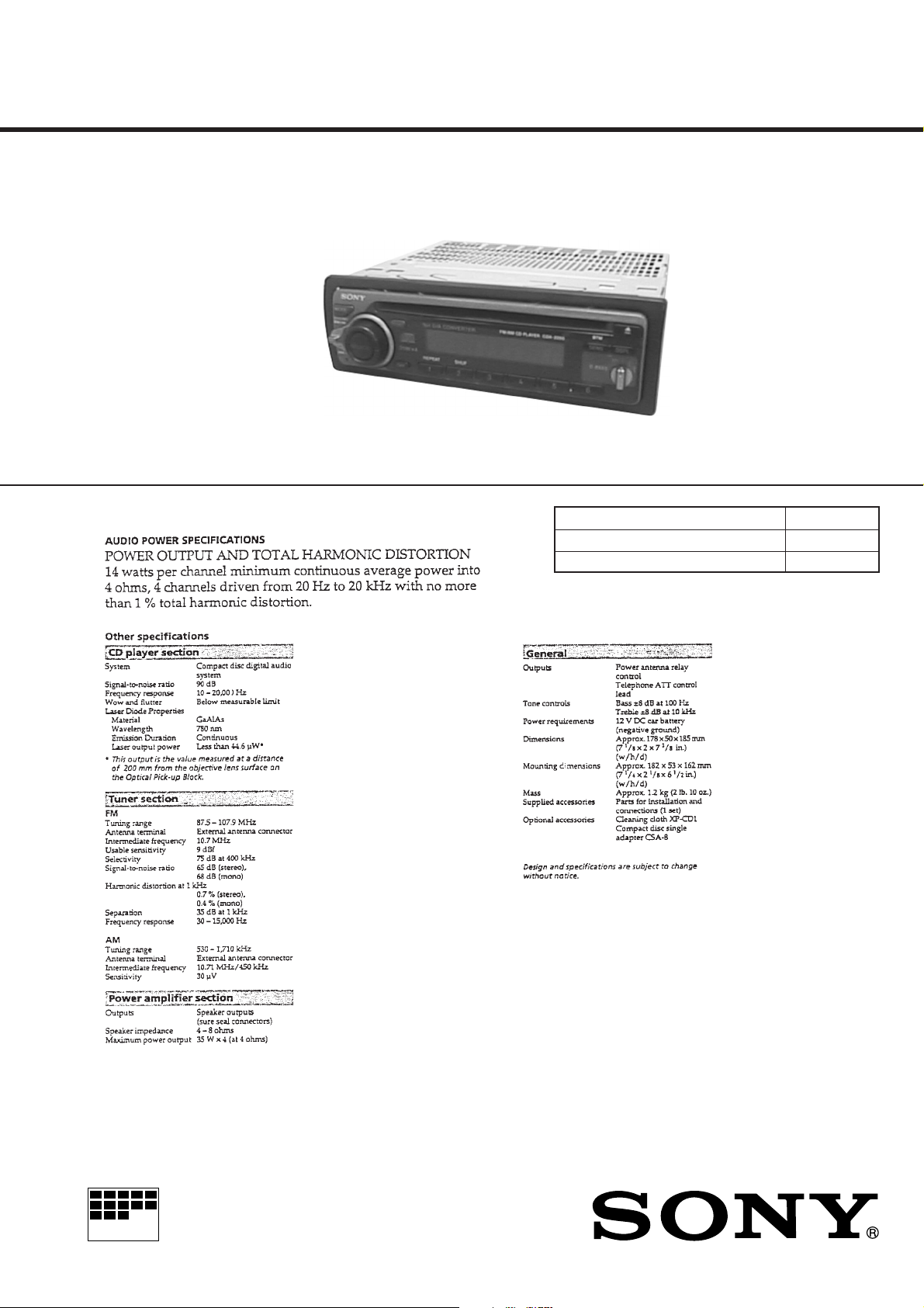
Photo: CDX-2250
SPECIFICATIONS
US Model
Canadian Model
CDX-2250
E Model
CDX-3500
Model Name Using Similar Mechanism CDX-2180
CD Drive Mechanism Type MG-363X-121
Optical Pick-up Name KSS-521A
MICROFILM
FM/AM COMPACT DISC PLAYER
– 1 –
SECTION 4
DIAGRAMS
4-1. IC PIN DESCRIPTION
• IC801 µPD17705GC-537-3B9 (SYSTEM CONTROL)
Pin No. Pin Name I/O Pin Description
1 SIRCS I SIRCS input (A/D)
2 IN-SW I CD mechanism position detection
3 D-SW I CD mechanism position detection
4 SELF-SW I CD mechanism position detection
5 L-SW I LIMIT switch
6 LM-EJ O Loading motor control (Eject direction)
7 LM-LOD O Loading motor control (Loading direction)
8 AMP/ANT-ON O Power control for amplifier.
9 MONO O Force MONO output
10 SD I SD signal input
11 BAND-SW I Initialize switch input terminal
12 AREA1-SW I Initialize switch input terminal
13 AREA2-SW I Initialize switch input terminal
14, 15 RE1, 2 I Rotary encoder input 1, 2
16 SEEK O SEEK output
17 CD-ON I/O Servo drive power
18 FM-ON I/O FM select output
19 TU-ON I/O AM select output
20 NC — Not used.
21 GND3 — Ground
22 KEYIN3 I Not used (Connect to ground)
23, 24 KEYIN2, 1 I A/D key input 2, 1
25 ROT-IN I Rotary commander input
26 S-METER I FM and AM common signal meter A/D conversion input
27 TEST-SW I TEST mode select input
28 AM-IFC I AM center frequency input
29 FM-IFC I FM center frequency input
30 VDD2 — Power supply (+5 V)
31 VCOH-FM I Local oscillation frequency input (FM)
32 VCOL-AM I Local oscillation frequency input (AM)
33 GND2 — Ground
34 NC — Not used.
35 EO1-PDOUT O Error out output
36 TESTO — Connect to ground
37 AM-ON(TU-ON) O AM power output (AM select)
38 FM-ON(FM/AM) O FM power output (FM select)
39 LCL/DX O LOCAL/DX select (“H” : LOCAL, “L” : DX)
40 BEEP O BEEP output
41 ACC-IN I Accessory input
42 SCOR I SUBQ data read request
43 MUTE O System mute output
44 AMP-MUTE O Power amplifier mute output
45 TEL-MUTE O Telephone mute output
46 NC — Fixed at “H” in this set.
47 VOL-CE O Electric volume chip select
48 VOL-CLK O Electric volume serial clock
49 VOL-DATA O Electric volume serial data
50 EMPHO O De-emphasis control output
51 PW-ON O System power control
52 MD-ON O Loading motor power
53 CD-ON O Servo drive power
– 19 –
Pin No. Pin Name I/O Pin Description
54 ILL-ON O Illumination output
55 C.ALARM I Caution alarm select input (Used/Not used)
56 NC I Not used (Connect to ground)
57 NC — Fixed at “H” in this set.
58 LCD-CE O LCD drive chip select output
59 EZ-SEL I SHIFT + input
60 SENS I Information input from servo IC.
61 FOK I Focus OK input
62 LD-ON O Laser diode control
63 NC — Not used. (Connect to ground)
64 [IN] ST/MONO I/O Used for both STEREO indicator display input and force MONO output. (FM)
[OUT] MONO
65 LCD-CKO O LCD driver serial clock output
66 LCD-So O LCD driver serial data output
67 INH O INHbit output
68 SQ-CKo O Q data read serial clock output
69 CD-RST O Servo IC/DAC reset output
70 SQ-SI I Q data input
71 CD-SO O Serial data output to servo IC.
72 CD-LAT O Data latch output to servo IC.
73 CD-CKO O Serial clock output to servo IC.
74 VREF — Not used.
75 GND1 — Ground
76 X-OUT — Crystal oscillator connection (4.5 MHz)
77 X-IN I Crystal oscillator connection (4.5 MHz)
78 BU-IN I Back-up detection
79 VDD1 — Power supply (+5 V)
80 RESET I RESET input
– 20 –
 Loading...