

Page 1

CDU711
CD-ROM Drive Unit
User’s Guide
3-861-825-11(1)
CDU711
CD-ROM Drive Unit
©1997 by Sony Corporation Printed in Japan
User’s Guide
Page 2
Owner’s Record
The model and serial numbers are located on the top side of the drive. Record these
numbers in the spaces provided below. Refer to them whenever you call upon your sales
representative regarding this product.
Model No. __________________ Serial No. ___________________
WARNING
To prevent fire or shock hazard, do not expose the unit
to rain or moisture.
To avoid electrical shock, do not open the cabinet.
Refer servicing to qualified personnel only.
CAUTION
The use of optical instruments with this product will increase eye hazard.
The use of controls or adjustments or performance of procedures other than those
specified herein may result in hazardous radiation exposure.
This unit uses CD-ROM discs with the following mark.
When you use this unit as an audio CD player, use
compact discs with the following mark.
CAUTION INVISIBLE LASER RADIATION WHEN OPEN. DO NOT
VORSICHT UNSICHTBARE LASERSTRAHLUNG, WENN ABDECKUNG
ADVARSEL USYNLIG LASERSTRÅLING VED ÅBNING SE IKKE IND I
ADVARSEL USYNLIG LASERSTRÅLING NÅR DEKSEL ÅPNES. STIRR
V ARNING OSYNLIG LASERSTRÅLNING NÄR DENNA DEL ÄR
V AR O! A V ATTAESSA OLET ALTTIINA NÄKYMÄTTÖMÄLLE
STARE INTO BEAM OR VIEW DIRECTLY WITH OPTICAL
INSTRUMENTS.
GEÖFFNET. NICHT IN DEN STRAHL BLICKEN, AUCH
NICHT MIT OPTISCHEN INSTRUMENTEN.
STRÅLEN-HELLER IKKE MED OPTISKE INSTRUMENTER.
IKKE INN I STRÅLEN ELLER SE DIREKTE MED OPTISKE
INSTRUMENTER.
ÖPPNAD. STIRRA EJ IN I STRÅLEN OCH BETRAKTA EJ
STRALEN MED OPTISKA INSTRUMENT.
LASERSÄTEILYLLE. ÄLÄ TUIJOTA SÄTEESEEN ÄLÄKÄ
KATSO SITÄ OPTISEN LAITTEEN LÄPI.
2
This label is located on
the top of the drive.
Dieser Aufkleber
befindet sich an der
Oberseite des Gehäuses.
Page 3

INFORMATION
You are cautioned that any changes or modifications not expressly approved in this
manual could void your warranty covering this equipment.
Note: This equipment has been tested and found to comply with the limits for a Class B
digital device, pursuant to Part 15 of the FCC Rules. These limits are designed to
provide reasonable protection against harmful interference in a residential installation.
This equipment generates, uses, and can radiate radio frequency energy and, if not
installed and used in accordance with the instructions, may cause harmful interference to
radio communications. However, there is no guarantee that interference will not occur in
a particular installation. If this equipment does cause harmful interference to radio or
television reception, which can be determined by turning the equipment off and on, the
user is encouraged to try to correct the interference by one or more of the following
measures:
– Reorient or relocate the receiving antenna.
– Increase the separation between the equipment and receiver.
– Connect the equipment into an outlet on a circuit different from that to which the
receiver is connected.
– Consult the dealer or an experienced radio/TV technician for help.
CLASS 1
LASER PRODUCT
LASER KLASSE 1
PRODUKT
This CD-ROM Drive Unit is classified as a CLASS 1
LASER PRODUCT.
The CLASS 1 LASER PRODUCT label is located
on the top of the drive.
Bei diesem CD-ROM-Laufwerk CDU711 handelt es
sich um ein Laser-Produkt der Klasse 1.
LUOKAN 1 LASERLAITE
KLASS 1 LASER APPARAT
Ein entsprechender Aufkleber mit der Beschriftung
LASER KLASSE 1 PRODUKT befindet sich auf der
Oberseite des Geräts.
Diese Ausrüstung erfüllt die Europäischen EMC-Bestimmungen für die Verwendung in
folgender/folgenden Umgebung(en):
• Wohngegenden
• Gewerbegebiete
• Leichtindustriegebiete
(Diese Ausrüstung erfüllt die Bestimmungen der Norm EN55022, Klasse B.)
3
Page 4

Trademarks
• MS-DOS is a registered trademark of Microsoft Corporation.
• IBM PC, PC/XT, and PC/AT are registered trademarks of International Business
Machines Corporation.
• HP Vectra is a registered trademark of the Hewlett-Packard Company.
• Molex is a registered trademark of Molex, Inc.
• AMP is a registered trademark of AMP, Inc.
4
Page 5

Contents
Introduction 6
Features.............................................................................................. 6
Software Requirement ........................................................................ 7
Example of System Setup .................................................................. 7
Location and Function of Parts and Controls 8
Front Panel ......................................................................................... 8
Rear Panel.......................................................................................... 9
Precautions 10
Installing the Drive in Your Computer 11
Preparation ....................................................................................... 11
Setting the Jumpers.......................................................................... 12
Opening the Computer ..................................................................... 13
Preparing a Space for the Drive ....................................................... 14
Mounting the Drive ........................................................................... 15
Connecting the Drive ........................................................................ 16
Mounting the Host Adapter ............................................................... 18
Reassembling the Computer ............................................................ 19
Installing the Software Driver 20
How to Install .................................................................................... 20
Operating the Drive 21
Starting the Drive .............................................................................. 21
Ejecting the Disc ............................................................................... 23
How to Use the Disc Locks............................................................... 24
Specifications 26
5
Page 6

Introduction
Features
The CDU711 is an internal CD-R OM (Compact Disc Read-Onl y
Memor y) drive unit designed f or use with an IBM PC, HP V ectra, or
compatib le computer . It can read as m uc h as 540 Mb ytes of digital
data stored in a single CD-ROM disc.
The CDU711 has the f ollo wing f eatures:
General
•5 1/4 inch half-height drive form factor.
• 256-kbyte buffer memory ATA-PI compliant (SFF-8020)
• Audio CD like drawer loading of a disc without using a caddy.
• Power loading and power eject of a disc. The disc can also be
ejected manually.
• Housed in an airtight frame casing.
Supported disc formats
• Reads data from CD-ROM, CD-ROM XA, CD-I and CD-I Ready
format discs, and from CD-EXTRA and CD TEXT discs.
• Reads data from CD-BRIDGE format discs including PHOTOCD.
• Reads standard CD-Digital Audio encoded discs.
• Reads Video CD discs.
Performance
• Supports quadruple, 8 times and Max. 32 times speed operations
with real time error correction.
• Fast access time ensuring reliable high-speed data access.
6 Introduction
Audio
• Outputs 16-bit digital audio data over the ATA interface.
• Equipped with audio line output and headphones jack for audio
CD playback.
Note:
The CDU711 is not equipped with an ADPCM audio cir cuitr y
required to support CD-ROM XA and CD-I compatible audio
modes. In addition, the unit does not support the CD-I graphic
decoding function; it has to be provided by the system.
Page 7
Software Requirement
T o access data on CD-R OM discs, the appr opriate de vice driver and
MSCDEX (supplied with the host adapter) must be installed in your
computer when the OS is MS-DOS/Windo ws 3.1. See the man ual
that comes with the host adapter for details.
The application software you need for using the data on a CD-ROM
disc depends on the type and f ormat of the tar get data. See the
manual supplied with your CD-ROM disc for instructions.
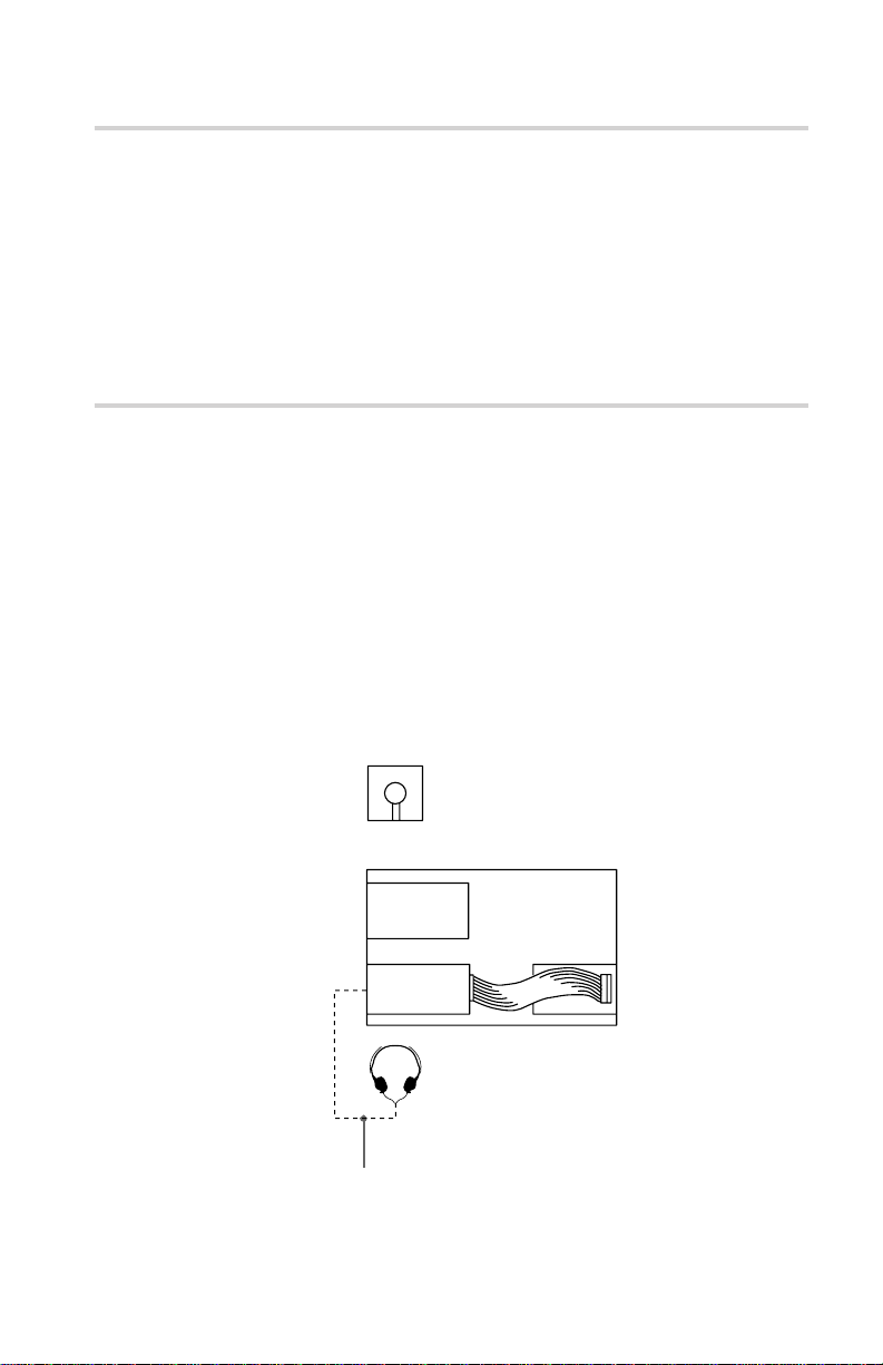
Example of System Setup
To use the CD-R OM drive unit, the f ollo wing components are
required:
• Computer (IBM PC, PC/XT, PC/AT, HP Vectra, or equivalent)
• IDE host adapter (ATA compliant)
• Floppy disk drive
• IDE interface cable (40 ≤ 40 pin flat cable)
• Software (Device driver, Utilities)
The following is an example of system setup.
Software
Floppy disk
drive
CD-ROM
Drive
Audio cable
Host computer
Host adapter
7Introduction
Page 8

Location and Function of Parts and Controls
Front Panel
1
34 56
2
11
1Disc drawer
11
Accepts a CD-ROM disc on its tray.
22
2 Headphones jack
22
Accepts a stereo headphones set. Analog audio signals are
output.
33
3 Volume control
33
Controls the volume level of sound output from the headphones
jack 2.
44
4Busy indicator
44
This amber indicator lights or flashes to indicate one of the
following unit conditions.
• Steady lit: TOC (table of contents) read, seek data read,
or audio playback in progress.
• Flashing: Drawer in motion.
55
5 Emergency eject hole
55
Used to open the disc drawer manually when neither the eject
button 6 nor a software command works. Insert a pointed
object, such as a paper clip, into this hole and push.
66
6 Eject button
66
Opens and closes the disc drawer.
8 Location and Function of Parts and Controls
Page 9

Rear Panel
Pin 1
2
1
11
1Unused
11
22
2ANALOG AUDIO connector
22
Outputs analog audio signals.
33
3 Configuration Jumpers
33
See page 12 for details.
44
4 INTERFACE CONNECTOR (IDE bus)
44
Connect to IDE host adapter using a connecting cable.
55
5 DC INPUT (power-in) connector
55
Connect to the power supply of the host computer.
45
3
Location and Function of Parts and Controls
9
Page 10

Precautions
■ Installation
• Avoid placing the drive in a location subject to:
– high humidity
– high temperature
– excessive dust
– mechanical vibration
– direct sunlight
• Do not force the power cable. It is keyed to protect the drive.
■ Operation
• Do not move the drive when it is in use. Doing so may cause data
error and damage the optical pick-up.
• Avoid exposing the drive to sudden changes in temperature as
condensation may form on the lens inside the drive. Should the
surrounding temperature suddenly rise while the drive is turned
on, stop using the drive and leave the power on at least one hour
before operating it or turning it off. Operating the drive
immediately after a sudden increase in temperature may result in a
malfunction.
■ Transportation
• Close the disc drawer before moving the drive.
• Keep the original packing materials. When you need to ship the
drive to another location, repacking it in its original container will
help you transport it safely.
10 Precautions
Page 11

Installing the Drive in Your Computer
This section provides an example of instruction for installing the
CD-ROM drive unit into your personal computer using the IDE
Host Adaptor (A T A-Compliant).
To connect the CDU711 directl y to the PC’ s IDE por t, consult y our
PC manufacturer for instruction.
Preparation
Y ou need the f ollowing par ts and tools (these are not supplied with
the drive):
• A flat-blade screwdriver
• Four screws 3 mm in diameter and 6 mm in length.
• Two mounting rails if your computer has mounting tracks.
Unplug the computer and disconnect the cables attached to the back
to give yourself more room to work. Do not turn on the power of the
computer before completing the entire installation process.
11Installing the Drive in Your Computer
Page 12

Setting the Jumpers
Set the jumper s on the rear of the drive in accor dance with the
configuration of your computer system.
The jumpers are preset at the “MASTER” position as illustrated at
the factor y.
Notes for configuration jumpers:
• Designation of the Drive Number is generally set by inserting a
jumper pin on either the MASTER or the SLAVE pin.
• When the CDU711 is daisy-chained with a Hard Disk Drive on an
IDE Card, set the Hard Disk Drive as MASTER and the CDU711
as SLAVE.
• If the CDU711 is the only device connected to the IDE Card, set
the CDU711 as MASTER.
CSEL
SLAVE
MASTER
However , it should be noted that some per sonal computer s ma y use
CSEL in lieu of the f oresaid MASTER/SLA VE selection. In this
case , remo ve the e xisting jumper s fr om MASTER and SLA VE, and
set a jumper on CSEL. When the CSEL signal of the interface
connector is set lo w, the drive is designated as Drive 0. When the
CSEL is set high, the drive is designated as Drive 1.
Consult y our PC man ufacturer , IDE Car d man ufacturer or dealer f or
further details.
12 Installing the Drive Unit into the Computer
Page 13

Opening the Computer
1 If your computer has its rear side covered by a plastic panel
attached with plastic hook pad, pull it off.
Computer
2 Remove the cover mounting screws.
3 Remove the cover of the computer.
Remove the plastic panel.
Rear plastic panel
Cover mounting screw
Remove the screws.
Remove the computer cover.
Installing the Drive Unit into the Computer
13
Page 14

Preparing a Space for the Drive
1 Remove the screws and brackets securing the floppy disk drive
and the lower drive bay blanking plate.
Remove the screws
and brackets.
2 Disconnect the floppy disk drive.
Floppy disk drive
Lower dirve bay
blanking plate
Floppy disk drive
3 Remove the floppy disk drive and the blanking plate.
Installing the Drive Unit into the Computer
14
Floppy disk drive
Blanking plate
Page 15

Mounting the Drive
If mounting rails are necessar y, attac h them to the drive in the same
way as your floppy disk drive and slide the drive into the lower
drive ba y . If mounting rails are not required in y our system, scre w
the drive in place.
Slide the drive into the lower bay.
Installing the Drive Unit into the Computer
15
Page 16

Connecting the Drive
Connect the drive to the computer with the f ollo wing connector s:
• DC INPUT connector
• AUDIO OUT connector (if you plan to connect audio equipment)
• INTERFACE CONNECTOR.
INTERFACE CONNECTOR
■ DC INPUT connector
The pin assignment is as follows.
After matching the beveled edges, insert the plug of the power
supply cable to the DC INPUT connector and push it firmly in place.
Caution: Improper connection may damage the drive and void the
warranty .
AUDIO OUT
connector
+5 V DC +12 V DC
DC INPUT connector
DC INPUT connector
GND
16
Installing the Drive Unit into the Computer
Power supply cable
(4-pin connection cable)
Page 17

■ AUDIO OUT connector
The pin assignment is as f ollo ws:
■ INTERFACE CONNECTOR
1 Firmly insert one end of the interface cable into the INTER-
FACE CONNECTOR.
pin Audio Signal
1 R signal
2 ground
3 ground
4 L signal
Pin 1
INTERFA CE
CONNECTOR
INTERFACE cable
2 Attach the other end of the cable to the host adapter.
Host adapter
INTERFACE cable
17Installing the Drive Unit into the Computer
Page 18

Mounting the Host Adapter
Install the host adapter in one of the available system expansion
slots of y our computer . Refer to the operating instructions inc luded
with the host adapter for complete instructions on installation and
settings.
Install the host adapter in
one of the expansion slots.
18 Installing the Drive Unit into the Computer
Page 19

Reassembling the Computer
1 Reinstall the floppy disk drive in the top drive bay.
Reinstall the floppy disk drive.
2 Reconnect the interface cables to the floppy disk drive.
3 Fasten the screws and front brackets as they were before.
4 Tuck the cables behind the drives so that they do not protrude
above the power supply module.
Tuck the cables.
Power supply
5 After checking the following points, slide the computer’s cover
on and fasten the cover mounting screws at the back of the
computer.
• Are the connections between the drive and computer correct?
• Are the jumpers set to the appropriate positions?
6 Remount the rear plastic panel and refer back to the proper
installation section if you answered “no” to either of the
questions above.
Installing the Drive Unit into the Computer
19
Page 20

Installing the Software Driver
The installation diskette enc losed in the pac kage contains tw o
software items:
• Installer
• Device driver for MS-DOS/Windows 3.1
Note:
Both Microsoft CD-ROM Extensions (MSCDEX) or equivalent and
Son y’s De vice Driver are required to run the CDU711 under the
MS-DOS and Windo ws 3.1 en vironment.
Therefore, prior to loading the installation diskette, make sure that
the MSCDEX is in the DOS directory of your hard disk drive
(C:\DOS). Although MSCDEX is inc luded in the most up-to-date
MS-DOS (ver . 6.2), you ma y need to obtain the software fr om y our
PC dealer if you do not have it.
The installer will automatically load MSCDEX via the
AUT OEXEC.B A T file and installs the De vice Driver via the
CONFIG.SYS file, if MSCDEX is already in Drive C:\DOS.
How to Install
At the DOS Pr ompt A: (Drive A active),
Installing the Software Driver
20
>A:\
Load the diskette into the flopp y disk Drive A, and type “install”.
>A:\install
and then, press the Enter ke y.
After installation, the following lines are added to CONFIG.SYS
and A UTOEXEC.B A T files.
in CONFIG.SYS:
Device=C:\DEV\A TAPI_CD.SYS /D:mscd000 /I:0
i n AUTOEXEC.BA T:
C:\DOS\MSCDEX.EXE /D:mscd000 /M:12 /V
Page 21

Operating the Drive
This section describes how to start the drive and eject a disc.
Starting the Drive
1 Turn on the power of your computer.
2 Press the eject button.
The drawer comes out automatically.
Press the eject button.
3 Place a disc in the drawer with its label side up.
Place a disc with
its label side up.
Operating the Drive
21
Page 22

Note:
When the drive is set up in vertical position, use the disc locks to
prevent your disc from falling. See “How to Use the Disc Locks” on
page 24 for details.
Disc locks
4 Gently push the drawer or press the eject button to close the
drawer.
The drive may begin reading the Table of Contents (TOC) data
when it accepts the disc. The busy indicator lights up in amber
while the drive is reading the TOC.
For subsequent drive operations, follow the instructions provided
with the application software you are using.
Note:
The busy indicator stays lit in amber if:
– the disc is not properly placed on the loading tray
– a malfunction occurs.
Operating the Drive
22
In either case, eject the disc and place it in the loading tray again
making sure that it sits pr operl y in the tra y. If doing this does not
solve the pr ob lem and the b usy indicator still remains lit in amber ,
consult your dealer or qualified service personnel.
Caution: Do not f orcib ly c lose the disc dra wer. Appl ying e xcessive
force ma y dama ge the loading mec hanism. The tra y’s mec hanism is
designed to operate with a “feather touch”.
Page 23

Ejecting the Disc
To eject the disc, press the eject b utton on the fr ont panel. The
dra wer comes out automaticall y.
Press the eject button.
Note:
The eject button does not work if it is disabled by:
– the software you are using
■ Opening the drawer manually in an emergency
Y ou can open the dra wer man uall y when it fails to come out b y
means of the eject b utton or software commands. To do this, follow
the procedure below:
1 Turn off the power of your computer.
2 Insert a pointed object, such as a paper clip, into the emergency
eject hole and push.
Approx. 40 mm
After removing a disc from the drive unit, consult your dealer or
qualified service personnel.
Operating the Drive
23
Page 24

How to Use the Disc Locks
The disc tray has four disc locks that prevent the disc from falling
when the drive is set up in vertical position.
Note:
When the drive is used in horizontal position, you do not need to
lock the disc.
■ Locking and unlocking
All of the four locks are set in the unlocked position (facing
outwar d) when the drive is shipped fr om the factor y. T o set the loc k
in the locked position, turn it with your fingers until you hear a click
so that it faces inward.
Disc locks
Operating the Drive
24
locked unlocked
to unlock
to lock
Page 25

When the drive’s right side is down
To facilitate disc handling, set the disc loc ks B, C and D into the
loc ked position, and lea ve the disc loc k A in the unloc ked position.
A
B
D
Top side
Right side
C
When the drive’s left side is down
To facilitate disc handling, set the disc loc ks A, C and D into the
locked position, and leave the disc lock B in the unlocked position.
C
Top side
B
Left side
DA
Operating the Drive
25
Page 26

Specifications
■ General
Host interface AT A-PI compliant
Disc
Acceptable discs CD-Digital A udio discs
Rotational speed
■ Drive performance
Data transfer rate
Sustained rate 600-1350 kb ytes (4-9 × CAV)
Burst rate 16.7 Mbytes/s (mode 4)
CD-ROM mode-1 data discs
CD-ROM mode-2 form1/form2 data discs
CD-ROM XA discs (readable)
Audio-combined CD-ROM discs
CD-I discs (readable)
CD-I Ready discs (readable)
CD Bridge discs
Photo CD discs (single and multi session)
CD EXTRA discs
Video CD discs, CD TEXT discs
2000 min
-1
(rpm)
4-9× CAV
4000 min
-1
(rpm)
8-18 × CAV
7000 min
-1
(rpm)
14-32 × CAV
1200-2700 kb ytes (8-18 × CAV)
2100-4800 kb ytes (14-32 × CAV)
IO CHANNEL READY supported
16.7 Mb ytes/s (Multiw ord DMA mode 2)
33.3 Mbytes/s (Ultra DMA)
■ Reliability
■ Audio
Specifications
26
Access time
(Random str oke) 80 ms (typical/14-32 × CAV)
Read err or rate (inc ludes retr y, with a standar d disc)
L-EC on 1 block /10
L-EC off 1 block /10
l2
9
bits
bits
Output level
Line out 0.75 V at 47 k Ω
Headphone 0.55 V at 32 Ω
Page 27

■ Environmental conditions
Operating
Temperature 5 °C to 50 °C (41 °F to 122 °F)
Humidity 10 % to 90 % (Max wet bulb 29 °C)
Atmosphere Non-condensing
Non-operating/Storage
Temperature –30 °C to 50 °C (–22 °F to 122 °F)
Humidity 10 % to 90 %
Atmosphere Non-condensing
■ Dimensions and mass
Dimensions 146 × 41.4 × 208 mm (w/h/d)
Mass 0.90kg (2 lb)
■ Power requirement
V olta ge +5 V ± 5 % DC and +12 V ± 10 % DC
Current Tra y Open/Close
3
(5
/4× 1 11/16 × 8 1/4 inc hes)
+5 V DC ; ≤1100 mA
+12 V DC ; ≤1100 mA
Seeking and Spin Up/Down
+5 V DC ; ≤1300 mA
+12 V DC ; ≤1800 mA
Hold Trac k State
+5 V DC ; ≤1300 mA
+12 V DC ; ≤750 mA
Standby/Sleep
+5 V DC ; ≤150mA
+12 V DC ; ≤20mA
■ Connectors
■ Laser
INTERFACE CONNECT OR
(with DC INPUT connector) AMP 179376-1 or equivalent
AUDIO OUT connector Molex 5046-04A or equivalent
T ype Semiconductor laser GaAlAs
Wave length 780 nm
Output power 0.5 mW
Design and specifications are subject to change without notice.
Specifications
27
Page 28

■ Dimension diagram
Important:
The o verhang of the scre ws should not e xceed 6.0 mm fr om the
surface of the side panels or the bottom plate.
148 (5
7
/
8
)
(8)
42.3
(111/16)
4-M3 Mounting screws
(4-on each side)
5
7
(
/
)
32
(
0.5
1
/
32
)
(
0.4
1
/
32
)
47.5
(17/8)(3
+
4-M3 Mounting screws
203
79.25
1
/
)
8
41.4
21.9
(1
11
(
7
/
/
16
8
)
(
)
13
10
/
32
)
+
(5
139.7
1
/
2
)
146
(5
3
/
4
)
28
+
Unit mm(inch)
Specifications
 Loading...