

Sony CDPSP-55 Service manual
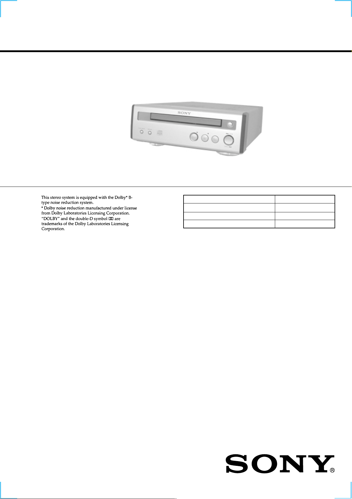
CDP-SP55
p
SERVICE MANUAL
CDP-SP55 is the CD section in CMT-SP55MD
or CMT-SP55TC.
Model Name Using Similar Mechanism NEW
CD Mechanism Type CDM55C-K6BD38
Base Unit Type BU-K6BD38
Optical Pick-up Type KSM-213DCP/Z-NP
AEP Model
UK Model
E Model
SPECIFICATIONS
System Compact disc and digital audio
Laser Semiconductor laser (λ=780 nm)
Laser output Max. 44.6 µW*
Frequency response 20 Hz – 20 kHz
Output
DIGITAL OPTICAL OUT: O
system
Emission duration: continuous
*This output is the value
measured at a distance of 200 mm
from the objective lens surface on
the Optical Pick-up Block with
7 mm aperture.
tical
General
Dimensions (w/h/d)
Mass
Design and specifications are subject to change
without notice.
Approx. 202 × 75 × 290 mm
Approx. 1.5 kg
MINI Hi-Fi COMPONENT SYSTEM
1

TABLE OF CONTENTS
1. SERVICING NOTE ·························································· 4
2. GENERAL ·········································································· 6
3. DISASSEMBLY
3-1. Case ···················································································· 7
3-2. Front Panel Assy ································································· 7
3-3. CD Mechanism Deck (CDM55C-K6BD38) ······················ 8
3-4. Main Board ········································································· 8
3-5. CAM, GEAR ······································································ 9
3-6. Holder Assy ········································································ 9
3-7. Optical Pick-up ································································· 10
3-8. BD Board ·········································································· 10
4. ELECTRICAL ADJUSTMENT ·································· 11
5. DIAGRAMS
5-1. Circuit Boards Location ··················································· 14
5-2. Block Diagram ································································· 15
5-3. Printed Wiring Board – BD Section – ······························ 16
5-4. Schematic Diagram – BD Section – ································· 17
5-5. Printed Wiring Board – Main Section – ··························· 18
5-6. Schematic Diagram – Main Section – ······························ 19
5-7. Printed Wiring Board – Loading Section – ······················ 20
5-8. Schematic Diagram – Loading Section – ························· 20
5-9. IC Block Diagram ···························································· 20
6. EXPLODED VIEWS
6-1. Case and Front Panel Section ··········································· 22
6-2. CD Mechanism Deck Section (CDM55C-K6BD38) ······· 23
6-3. Base Unit Section (BU-6BD38) ······································· 24
7. ELECTRICAL PARTS LIST ······································· 25
2
NOTES ON HANDLING THE OPTICAL PICK-UP
Parts No.
BLOCK OR BASE UNIT
The laser diode in the optical pick-up block may suffer electrostatic
break-down because of the potential difference generated by the
charged electrostatic load, etc. on clothing and the human body.
During repair, pay attention to electrostatic break-down and also
use the procedure in the printed matter which is included in the
repair parts.
The flexible board is easily damaged and should be handled with
care.
NOTES ON LASER DIODE EMISSION CHECK
The laser beam on this model is concentrated so as to be focused on
the disc reflective surface by the objective lens in the optical pickup block. Therefore, when checking the laser diode emission,
observe from more than 30 cm away from the objective lens.
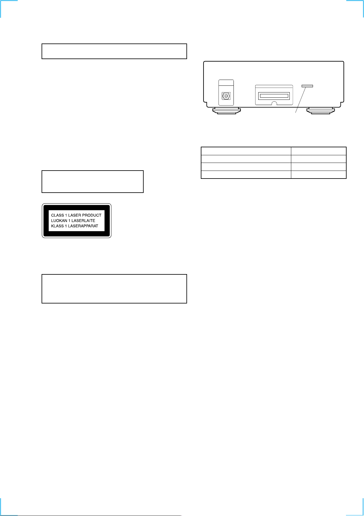
Laser component in this product is capable
of emitting radiation exceeding the limit for
Class 1.
MODEL IDENTIFICATION
— BACK PANEL —
MODEL
AEP,UK,AED models
HK,MY,SP models
KR model
• Abbreviation
AED : North European model
HK : Hong Kong model
MY : Malaysia model
SP : Singapore model
KR : Korea model
PARTS No.
4-229-674-0s
4-229-674-2s
4-229-674-3s
This appliance is classified as a CLASS 1 LASER product. The
CLASS 1 LASER PRODUCT MARKING is located on the rear
exterior.
CAUTION
Use of controls or adjustments or performance of procedures
other than those specified herein may result in hazardous radiation
exposure.
Notes on chip component replacement
• Never reuse a disconnected chip component.
• Notice that the minus side of a tantalum capacitor may be
damaged by heat.
Flexible Circuit Board Repairing
• Keep the temperature of soldering iron around 270˚C
during repairing.
• Do not touch the soldering iron on the same conductor of the
circuit board (within 3 times).
• Be careful not to apply force on the conductor when soldering
or unsoldering.
SAFETY-RELATED COMPONENT W ARNING!!
COMPONENTS IDENTIFIED BY MARK 0 OR DOTTED LINE WITH
MARK 0 ON THE SCHEMATIC DIAGRAMS AND IN THE PARTS
LIST ARE CRITICAL TO SAFE OPERATION. REPLACE THESE
COMPONENTS WITH SONY PARTS WHOSE PART NUMBERS
APPEAR AS SHOWN IN THIS MANUAL OR IN SUPPLEMENTS
PUBLISHED BY SONY .
3

SECTION 1
SERVICING NOTE
This unit cannot be repaired by itself.
When repairing, connect the whole system except for the speaker.
CD Text Display
• This unit displays CD text.
Text is displayed for the first 50 track only and will not be displayed from the 51st track onwards. Do not suspect a fault in this case.
In some cases, some special characters will not be displayed and may be replaced by other characters. Do not suspect a fault in this case.
Cold Reset
• The cold reset clears all data including preset data stored in the RAM to initial conditions. Execute this mode when returning the set to the
customer.
Procedure :
1. When the power ON, press the ?/1 button (TA) while pressing the TUNING MODE button (ST) and ML buttons (CDP)
together.
2. “COLD RESET” is displayed on the fluorescent indicator tube and reset is executed.
Hot Reset
• This mode reset the preset data kept in the memory. The hot reset mode functions same as if the power cord is plugged in and out.
Procedure :
1. When the power ON, press the ?/1 button (TA) while pressing the TUNING MODE button (ST) and lm buttons (CDP)
together.
2. Turn off the unit and reset is executed.
GC Test Mode
Procedure :
1. When the power ON, press the ?/1 button (TA) while pressing the TUNING MODE button (ST) and PLAY MODE buttons (CDP)
together.
2. Fluorescent indicator tube are all turned on.
3. Press TUNING MODE button (ST) to enter the model destination indecation mode. “SP55 CE2” appears.
4. Every pressing of TUNING MODE button (ST) changes the display in the following order.
MC Version t CD Version t ST Version t TC Version t TA Version t TM Version t model destination display.
5. Press DISPLAY button (ST) and the date appears as “ 00615a ”
Every pressing of DISPLAY button (ST) changes the display in the Version display and model destination display.
6. Press TUNER/BAND button (ST) to enter the key check mode.
7. In the key check mode, the fluorescent indicator tube displays “Key 0 Vol 0”. Each time a button is pressed, “Key” value increases.
However, once a button is pressed, it is no longer taken into account.
“Vol” Value increases like “1, 2, 3 ...” if rotating VOLUME knob (TA) in the clockwise direction, or decreases like “0, 9, 8 ...” if rotating
in the counterclockwise diretion.
8. To exit from this mode, press three buttons in the same procedure as step 1, or disconnect the power cord.
4
Aging Mode
• Mode for repeating operations of the CD player and TC deck automatically.
When errors occur:
Aging stops and a message indicating that an error has occurred such as “CD MEC ERR” is displayed.
(For details of errors, refer to “Error History Display Mode”.)
When no errors occur:
Aging is repeatedly performed.
Procedure:
1. Load any CD and a tape.
2. Select the function “ CD ” using the FUNCTION knob (TA).
3. While pressing the TUNING MODE button (ST) and H button (CDP), press the ?/1 button (TA).
4. “AGING” is displayed on the fluorescent display tube briefly.
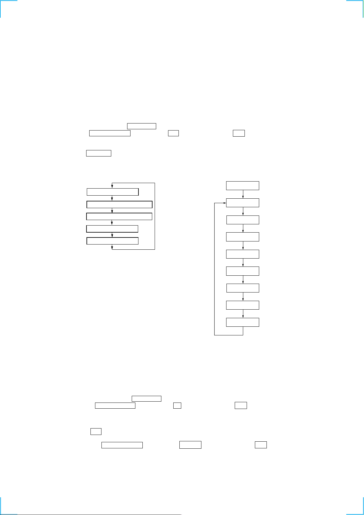
5. Operations are performed in the following sequence during aging.
Every pressing of DISPLAY button (ST) changes the display in the CD display and TAPE display.
CD : Cassette :
REW (Shut off) "TAPE AG-1"
Reading of TOC
Playback of first track (3sec.)
Playback of last track (3sec.)
CD tray open
CD tray close
6. To end aging, execute the cold reset.
Error History Display Mode
Mode for checking the history of errors which have occurred in the CD player.
Execute this mode after ending the aging mode.
PLAY
FF
REV PLAY
REW
FF
REW
OPEN
CLOSE
(2 min) "TAPE AG-2"
(Shut off) "TAPE AG-3"
(2 min) "TAPE AG-4"
(Shut off) "TAPE AG-5"
(Shut off) "TAPE AG-6"
(Shut off) "TAPE AG-7"
(Shut off)
"TAPE AG-8"
"TAPE AG-9"
Procedure:
1. Select the function “ CD ” using the FUNCTION knob (TA).
2. While pressing the TUNING MODE button (ST) and S button (CDP), press the ?/1 button (TA).
3. “EMC@@EDC**” id displayed.
@@ : Number of mechanism errors (Last 3 errors)
** : Number of errors (NO DISC ERROR) which occurred after chucking (Last 3 errors)
4. To end, press the ?/1 button (TA) and turn OFF the power.
Note: To erase the error history, perform cold reset.
(While pressing the TUNING MODE button (ST) and ML button (CDP), press the ?/1 button (TA).)
5
SECTION 2
GENERAL
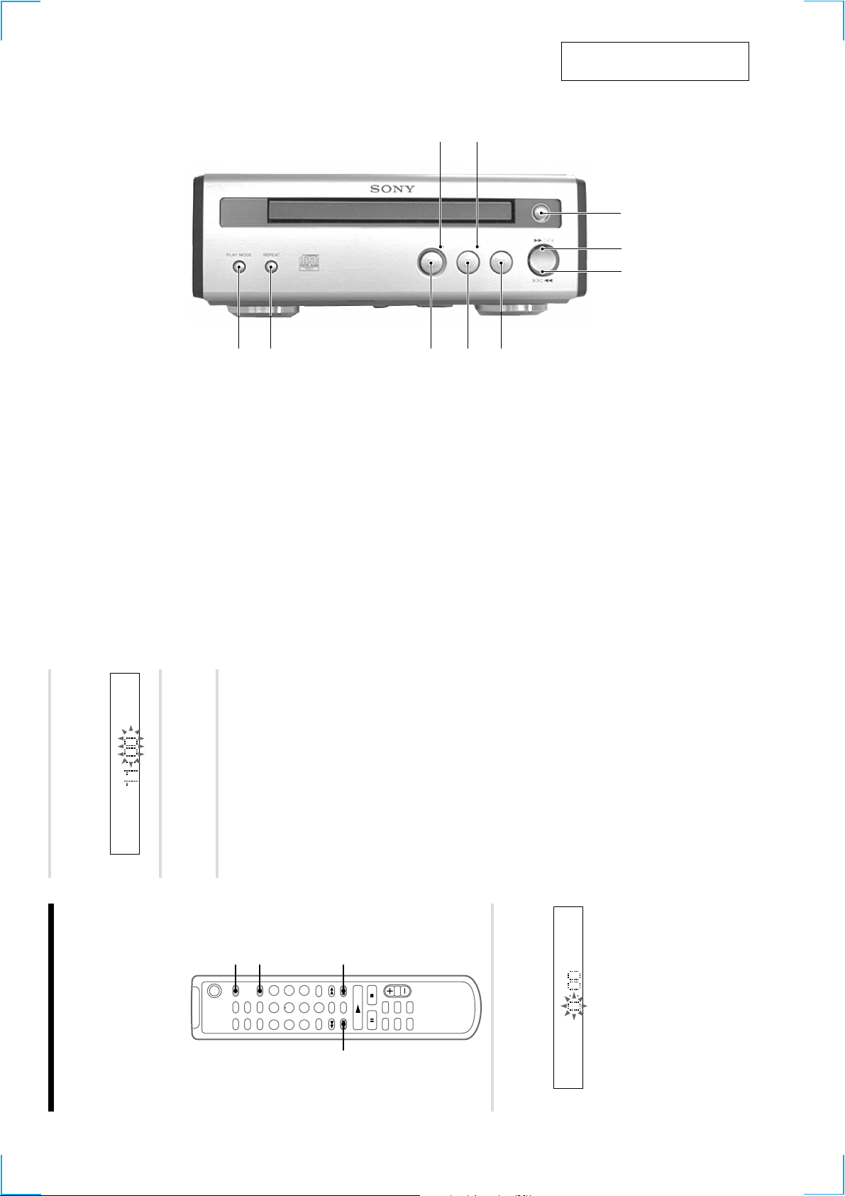
q;
This section is extracted from
instruction manual.
9
8
7
6
1 PLAY MODE button
2 REPEAT button
3 H button
4 S button
5 s button
1 2
3 4 5
6 lm button
7 ML button
8 A button
9 S indicator
q; H indicator
Press . or > to set the hour, then
The minute indication flashes.
press ENTER/YES.
2
Step 2: Setting the time
You must set the time beforehand to use the timer
functions.
The clock is on a 24-hour system for the European
Press . or > to set the minute,
then press ENTER/YES.
3
model, and a 12-hour system for other models.
The 24-hour system is used for illustration
purposes.
Set the time before turning on the system.
6
The clock starts.
If you made a mistake
Start over from step 1.
1
`/1
To change the preset time
You can change the preset time while the system
2,3
CLOCK” appears, then press ENTER/YES.
is on.
1 Press CLOCK/TIMER SET.
2 Press . or > repeatedly until “SET
3 Repeat steps 2 and 3.
2,32,3
while the system is off. If you press DISPLAY at
this time, the display back light lights up, making
• The built-in clock shows the time in the display
Tips
the clock easier to see.
seconds, and the lower dot flashes for the last 30
seconds of each minute.
• The upper dot of the colon flashes for the first 30
Press CLOCK/TIMER SET while the
system is off.
The hour indication flashes.
1
8
SECTION 3
)
DISASSEMBLY
Set Case Front Panel Assy
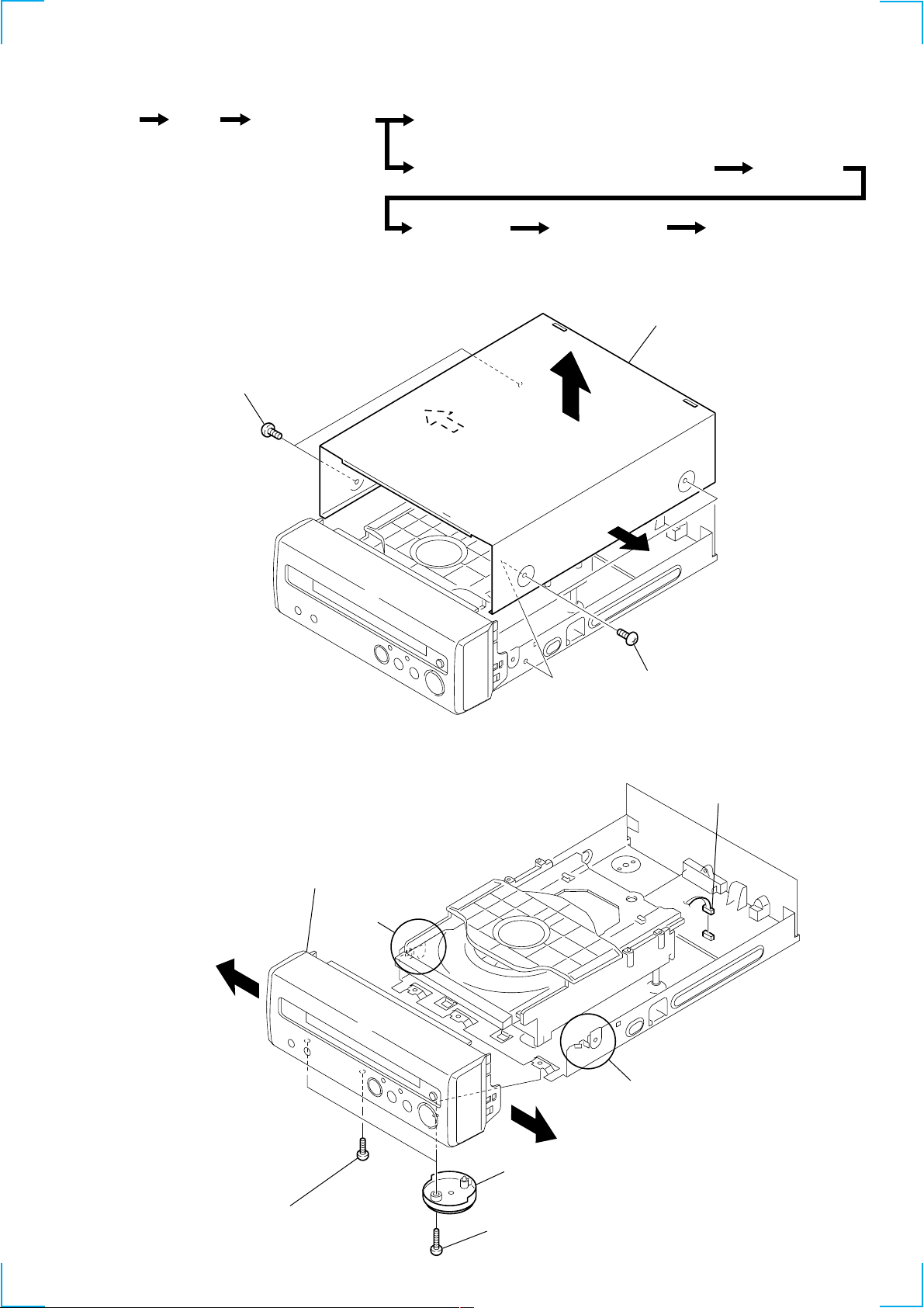
3-1. CASE
1 two screws
(case 3 TP2)
Main Board (Page 8)
CD Mechanism Deck (CDM55C-K6BD38)
Holder Assy Optical pick-up
(Page 9) (Page 10)
4 case
3
2
2
Cam, Gear
(Page 9) (Page 8)
BD Board
(Page 10)
3-2. FRONT PANEL ASSY
1 two screws
(case 3 TP2
1 connector
(CN711)
5 front panel assy
claws
claws
4 screw (BVTP 3x12)
3 two foot assy's
2 two screws
(BVTP 3x12)
7
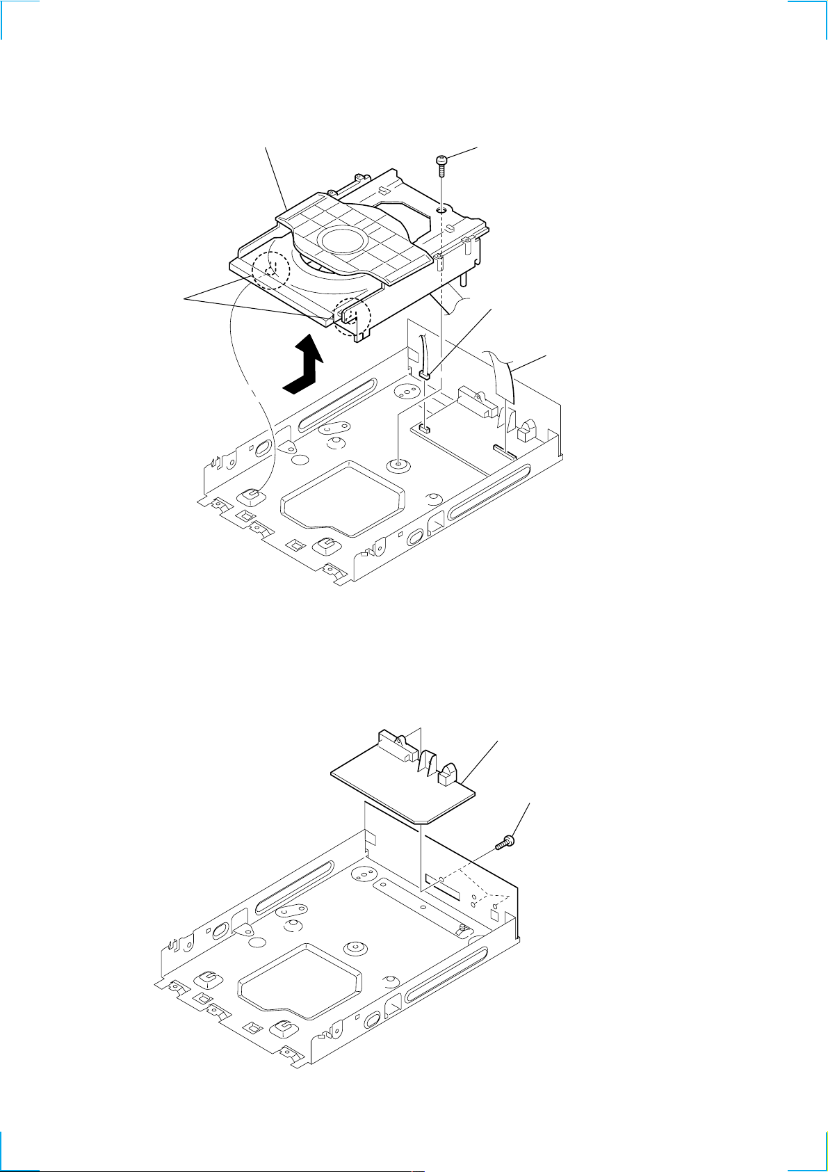
3-3. CD MECHANISM DECK (CDM55C-K6BD38)
)
)
two claws
5 CD mechanism deck
4
3 screw (BVTP 3x8)
2 connector
(CN112)
1 flat type wire (19 core
(CN713)
3-4. MAIN BOARD
2 main board
1 screw (BVTP 3x8
8
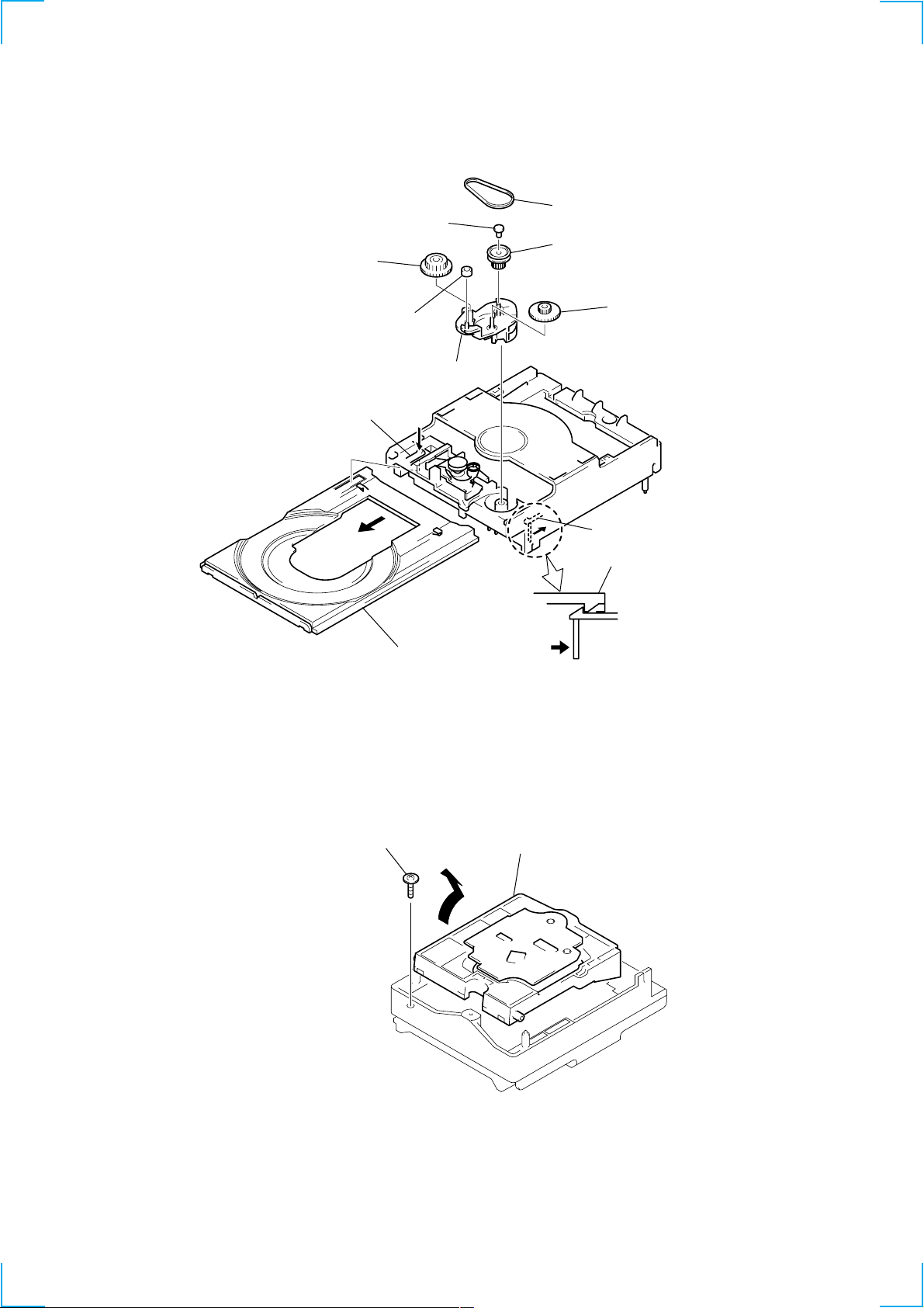
3-5. CAM, GEAR
y
8 gear (B)
2 Push the claw in tne
direction of arrow C.
A
5 bushing
7 roller
0 cam (CDM55)
C
3 Pull out the tray.
4 belt (CDM55)
6 pulley (LDG)
1 Pull out the tray in the arrow direction A,
B
B
and release the lock while pressing
this claw in the arrow direction B.
Release
9 gear (A)
3-6. HOLDER ASSY
1 floating screw
(PTPWH M2.6)
2 Remove the Holder (BU) ass
in the direction of arrow A.
A
9
 Loading...