

Sony CDPEX-77 Service manual

CDP-EX77
SERVICE MANUAL
CDP-EX77 is the CD player section
in MHC-EX66, DHC-EX77MD/MD77
SPECIFICATIONS
AEP Model
UK Model
E Model
Model Name Using Similar Mechanism HCD-MD5
CD Mechanism Type
Base Unit Name BU-5BD19
Optical Pick-up Name KSS-213B/K-N
CDM38A-5BD19
System Compact disc and digital audio system
Laser Semiconductor laser (λ = 780 nm)
Laser output Max. 44.6 µW*
Frequency response 2 Hz to 20 kHz (± 0.5 dB)
CD OPTICAL DIGITAL OUT
(Square optical connector jack, rear panel)
Dimensions (w/h/d) incl. projecting parts and
controls: Approx. 280 × 122.5 × 347 mm
Mass Approx. 3.7 kg
Design and specifications are subject to change without notice.
Emission duration: continuous
* This output is the value measured at a distance of
200 mm from the objective lens surface on the Optical Pick-up Block with 7 mm aperture.
MICROFILM
COMPACT DISC PLAYER
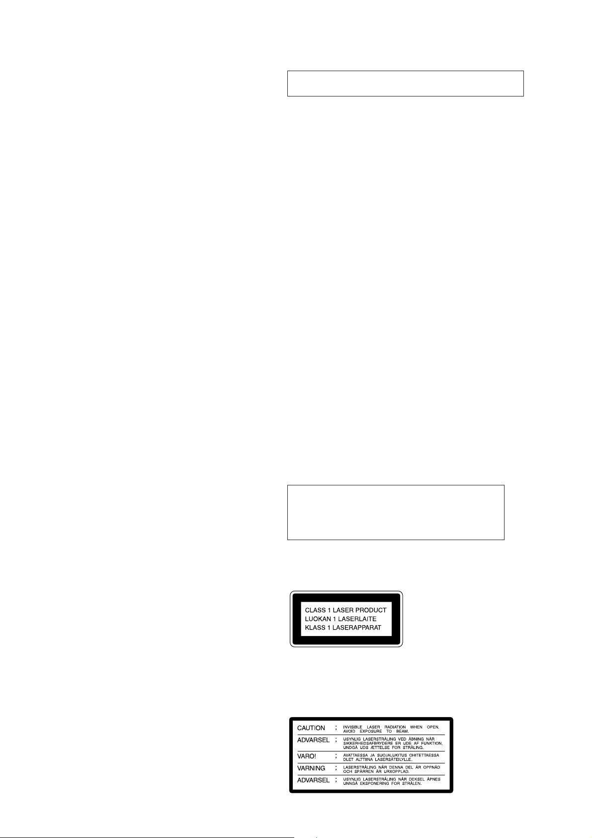
TABLE OF CONTENTS
1. SERVICING NOTES
1-1. Power Supply During Servicing ...................................... 3
1-2. Fluorescent Indicator Tube/Key Check Mode ................. 3
2. GENERAL ................................................................... 4
3. DISASSEMBLY.......................................................... 9
4. ELECTRICAL ADJUSTMENTS ......................... 14
NOTES ON HANDLING THE OPTICAL PICK-UP
BLOCK OR BASE UNIT
The laser diode in the optical pick-up block may suffer electrostatic break-down because of the potential difference generated
by the charged electrostatic load, etc. on clothing and the human
body.
During repair, pay attention to electrostatic break-down and also
use the procedure in the printed matter which is included in the
repair parts.
The flexible board is easily damaged and should be handled with
care.
5. DIAGRAMS ................................................................ 16
5-1. Printed Wiring Board – BD Section – ............................. 17
5-2. Schematic Diagram – BD Section – ................................ 19
5-3. Schematic Diagram
– MAIN/PANEL/MOTOR Section – .............................. 23
5-4. Printed Wiring Boards
– MAIN/PANEL/MOTOR Section – .............................. 27
5-5. IC Pin Function Description ............................................ 34
6. EXPLODED VIEWS ................................................ 36
7. ELECTRICAL PARTS LIST................................ 41
NOTES ON LASER DIODE EMISSION CHECK
The laser beam on this model is concentrated so as to be focused
on the disc reflective surface by the objective lens in the optical
pick-up block. Therefore, when checking the laser diode emission, observe from more than 30 cm away from the objectiv e lens.
LASER DIODE AND FOCUS SEARCH OPERATION
CHECK
Carry out the “S curve check” in “CD section adjustment” and
check that the S curve waveforms is output three times.
Notes on chip component replacement
• Never reuse a disconnected chip component.
• Notice that the minus side of a tantalum capacitor may be dam-
aged by heat.
Flexible Circuit Board Repairing
• Keep the temperature of the soldering iron around 270 ˚C dur-
ing repairing.
• Do not touch the soldering iron on the same conductor of the
circuit board (within 3 times).
• Be careful not to apply force on the conductor when soldering
or unsoldering.
CAUTION
Use of controls or adjustments or performance of
procedures other than those specified herein may
result in hazardous radiation exposure.
SAFETY-RELATED COMPONENT WARNING!!
COMPONENTS IDENTIFIED BY MARK ! OR DOTTED LINE
WITH MARK ! ON THE SCHEMATIC DIAGRAMS AND IN
THE PARTS LIST ARE CRITICAL TO SAFE OPERATION.
REPLACE THESE COMPONENTS WITH SONY PARTS WHOSE
PART NUMBERS APPEAR AS SHOWN IN THIS MANUAL
OR IN SUPPLEMENTS PUBLISHED BY SONY.
This appliance is classified as a CLASS 1 LASER product.
The CLASS 1 LASER PRODUCT MARKING is located on
the rear exterior.
Laser component in this product is capable of emitting radiation
exceeding the limit for Class 1.
The following caution label is located inside the unit.
– 2 –
SECTION 1
b
SERVICING NOTES
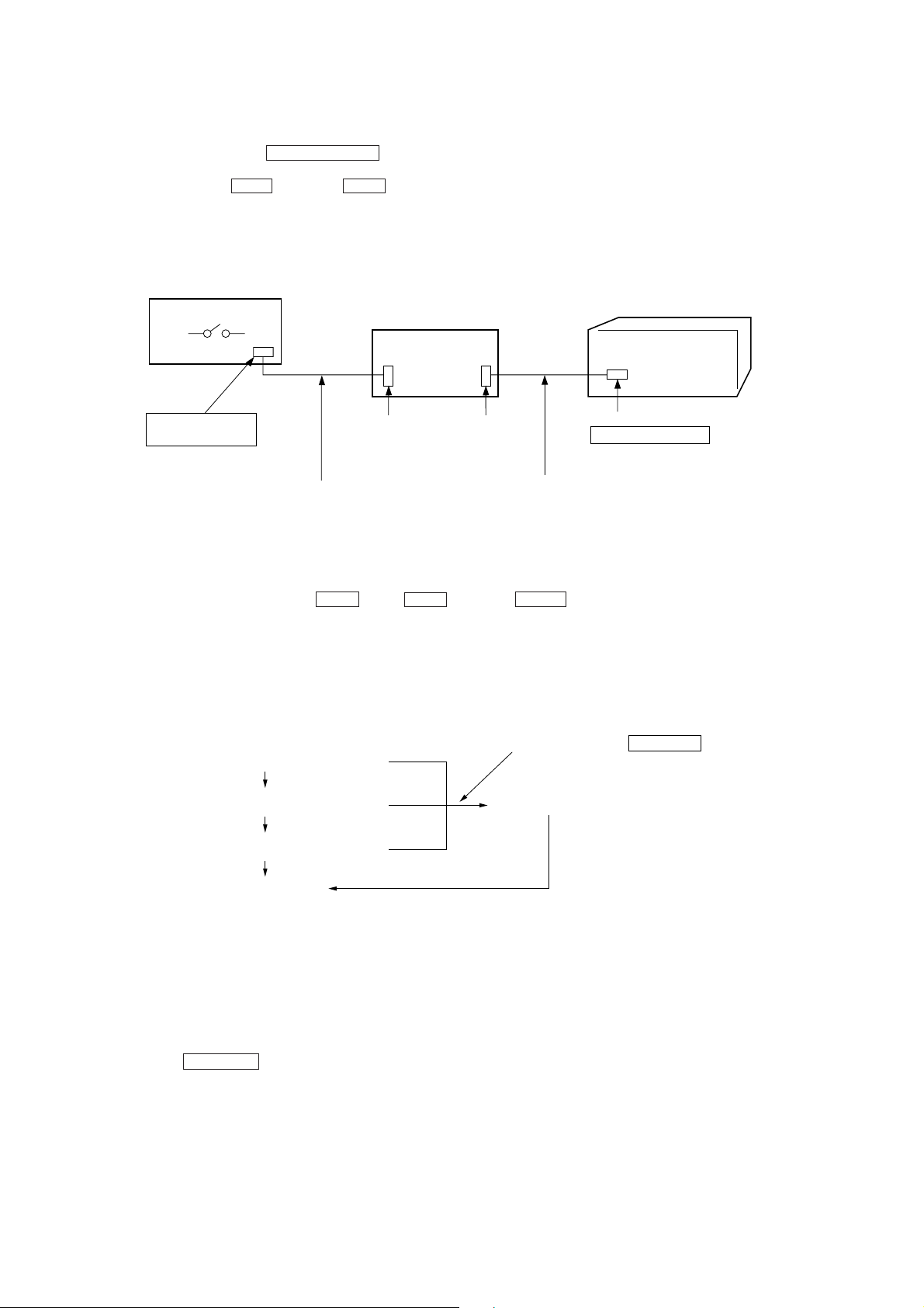
1-1. Power Supply During Servicing
This unit is not able to operate on its own because it does not have its own power supply. During servicing, connect to other units.
Power is supplied when the SYSTEM POWER button of the amplifier (TA-EX66/EX77) is turned ON.
If the other units are not available, use a service box (PFJ-1) and jig (J-2501-078-A).
In this case, press the STOP button and TIME button simultaneously to turn on the power.
[Connection Diagram]
SERVICE BOX (PFJ-1)
POWER SW
FH-E939, 838, 937
CDP/TC
CORD WITH CONNECTOR 17 P
(Provided with PFJ-1)
JIG
(J-2501-078-A)
CN904
17P
CN902
7P
CORD WITH CONNECTOR 7 P
(Provided with unit)
CN101 7P
SYSTEM CONTROL
UNIT (CDP-EX77)
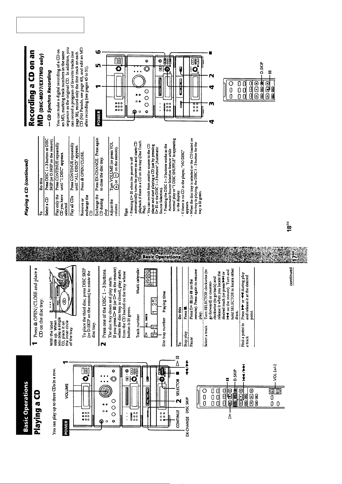
1-2. Fluorescent Indicator Tube/Key Check Mode
After turning on the power , press the STOP button, TIME button, and DISC 1 button simultaneously to perform the Fluorescent indicator tube check.
The steps of the Fluorescent Indicator Tube check mode will proceed onto the next one by the above multiple pressing.
During the Fluorescent Indicator Tube check mode, press any button or rotate the selector knob to set the key check mode.
To end the mode, press the above three buttons simultaneously.
Fluorescent Indicator Tube all lit mode
Multiple pressing
Segment pattern 1 mode
Multiple pressing
Segment pattern 2 mode
Multiple pressing
End of test mode
Press any key or roted the SELECTOR kno
Key check mode
Multiple pressing
Note 1) When the three buttons pressed to enter the Fluorescent Indicator T ube all lit mode are released together , the Fluorescent Indica-
tor Tube all lit mode will remain on. When released separately, the key check mode will be set soon after the Fluorescent
Indicator Tube all lit mode.
In “multiple pressing”, if the three buttons are pressed and released together, the next mode will be set. If not, the key check
mode will be set.
Note 2) In the key check mode, each time the button is pressed, the “KEY=” number on the Fluorescent indicator tube increases. When
the SELECTOR knob is rotated, the “KEY=” number on the Fluorescent indicator tube increases in the + direction and decreases in the – direction.
– 3 –
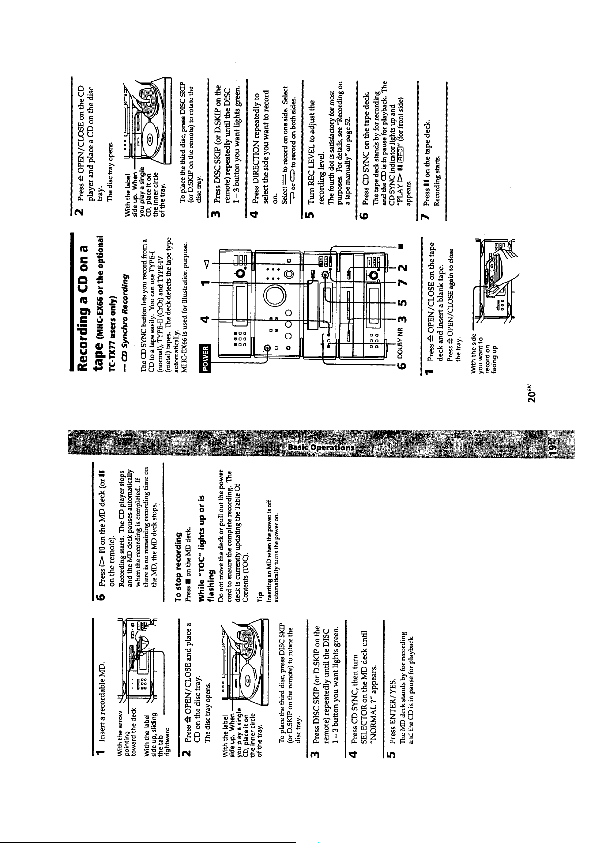
This section is extracted
from instruction manual.
SECTION 2
GENERAL
– 4 –
– 5 –
– 6 –
– 7 –
– 8 –
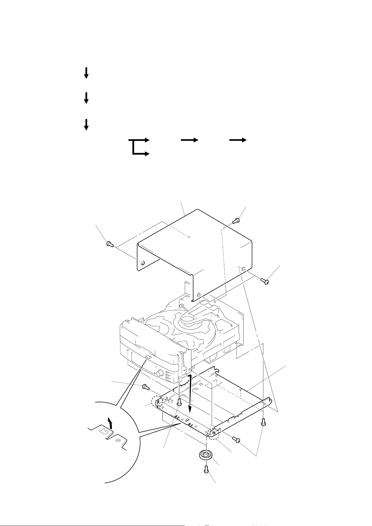
• This set can be disassembled in the order shown below.
CASE, CHASSIS
(Page 9)
LOADING PANEL
(Page 10)
FRONT PANEL SECTION
(Page 10)
SECTION 3
DISASSEMBLY
MAIN BOARD,
CD MECHANISM DECK
(Page 11)
Note: Follow the disassembly procedure in the numerical order given.
BASE UNIT
(Page 11)
TRAY SECTION
(Page 12)
CASE, CHASSIS
3
case
2
two screws
(case 3 TP2)
BD BOARD
(Page 13)
OPTICAL PICK-UP,
SLED MOTOR
(Page 13)
1
screw
(BVTT3
×
8)
2
two screws
(case 3 TP2)
6
screw
(BV3
×
7
10)
claw
7
claw
6
screw
(BV3
×
10)
– 9 –
5
4
two screws
(BV3
7
claw
two legs (F)
×
10)
6
four screws
(BV3
×
8
10)
chassis
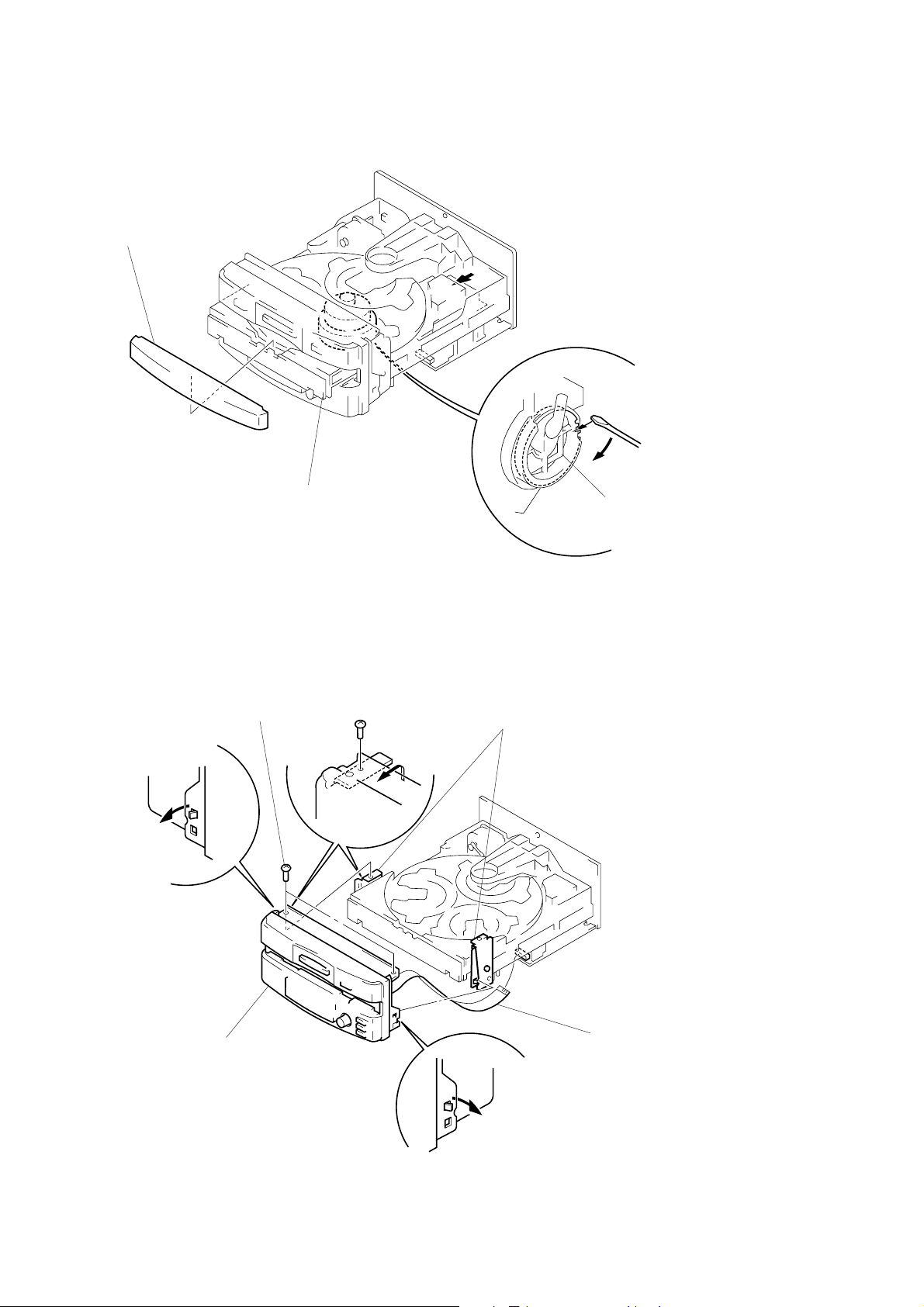
LOADING PANEL
3
loading panel
2
Pull the tray (slide).
1
Rotate the BU cam ass’y
to direction of the arrow
A
BU cam ass’y
A
.
FRONT PANEL SECTION
2
4
claw
5
front panel
section
two screws
(BV3
×
10)
3
two bosses
1
flat wire (29 core)
(CN305)
– 10 –
4
claw
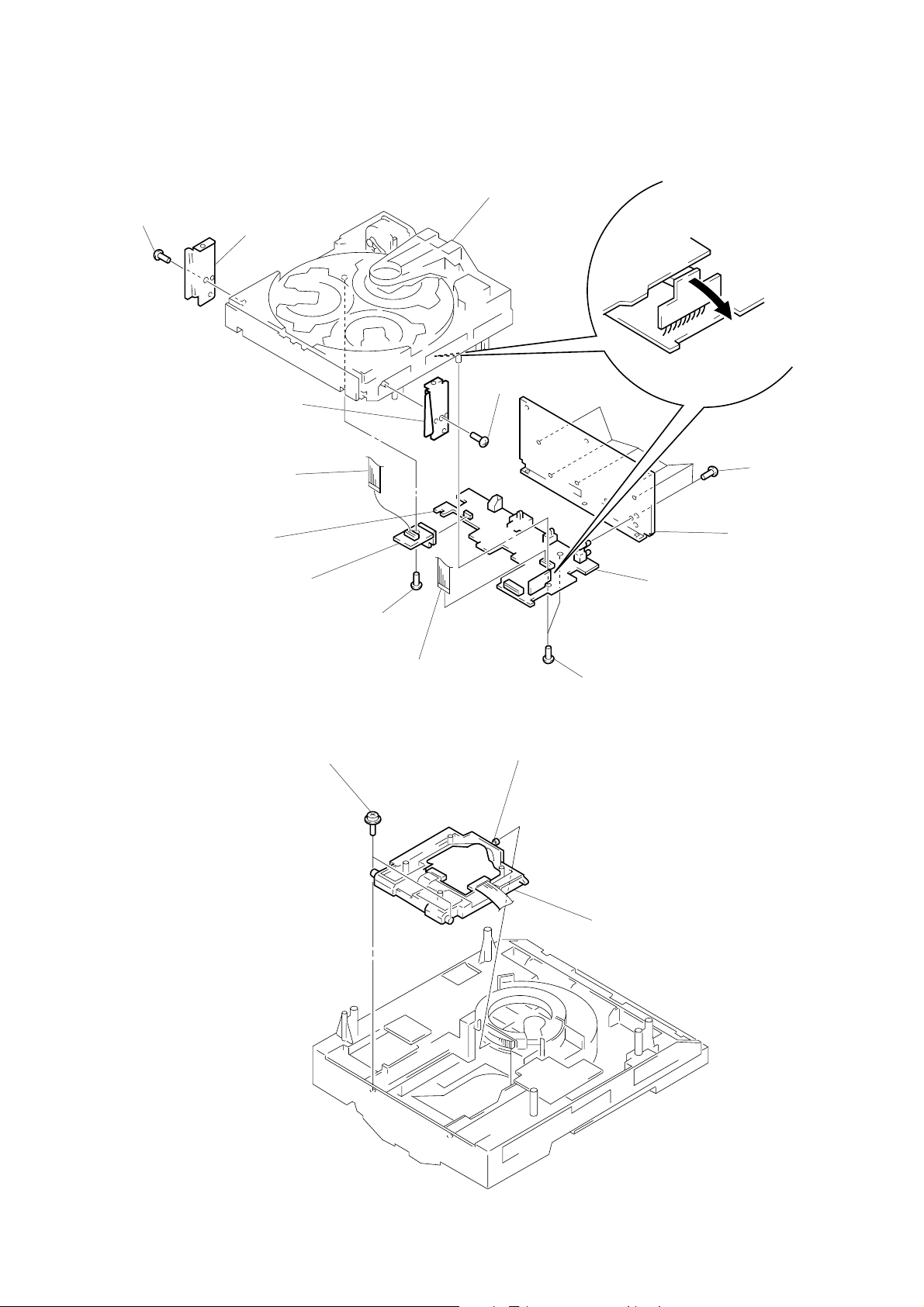
MAIN BOARD, CD MECHANISM DECK
!¡
screw
(BV3
×
10)
0
4
!™
bracket (L)
!™
bracket (R)
flat wire (8 core)
(CN702)
connector
(CN304)
9
relay
board
!£
CD mechanism deck
!¡
screw
(BV3
×
10)
6
main board
3
connector
(CN303)
2
1
Six screws
(BV3
back panel
×
10)
BASE UNIT
1
two yoke brackets
8
screws
(BV3
×
8)
7
flat wire (19 CORE)
(CN302)
2
boss
5
3
base unit
two screws
(BV3
×
8)
– 11 –
 Loading...