

Page 1
SECTION 3
)
)
DISASSEMBLY
Note: Follow the disassembly procedure in the numerical order given.
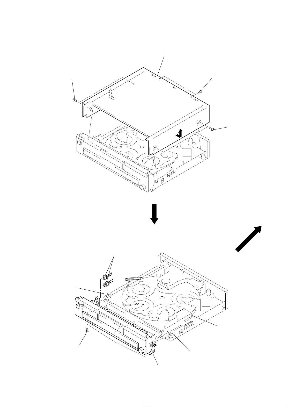
COVER (409537)
3 cover (409537)
1 two screws
(case3 TP2)
2 two screws
(BVTP3 × 8)
1 two screws
(case3 TP2
FRONT PANEL SECTION
4 claw
3 three screws
(BVTP3 × 8)
2 two connectors
(CN601, 602)
1 wire (flat type) (37 core
(CN301)
4 claw
5 front panel section
5
Page 2
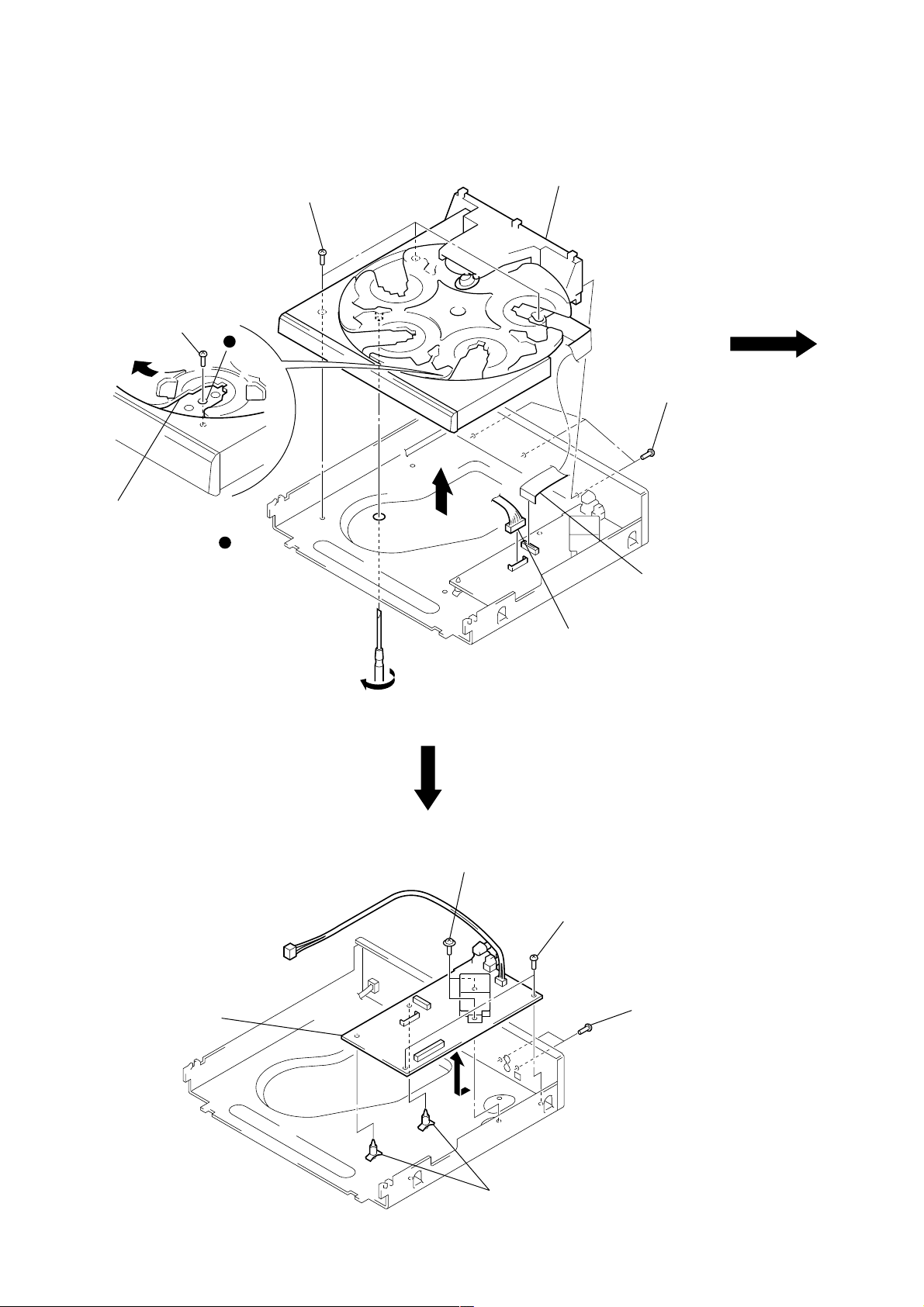
CD MECHANISM DECK (CDM59-5BD32A)
)
5 screw
(BVTP3 × 8)
4 Slide the tray until the screw
that fixes the table ass’y can be
seen through around hole
in the table ass’y.
3 three screws
a
a
(BVTP3 × 8)
9 CD mechanism deck
(CDM59-5BD32A)
2 three screws
(BVTP3 × 8)
6
7 wire (flat type) (21 core)
(CN302)
MAIN BOARD
5 MAIN board
8 connector
(CN311)
1 Insert a tapering driver from the bottom of the chassis,
and turn it in the direction of the arrow until the base unit
goes down to the lowest position.
3 two screws
(PTTWH3 × 6)
2 two screws
(BVTP3 × 8)
1 two screws
(BVTP3 × 8
4 two PC board holders
6
Page 3
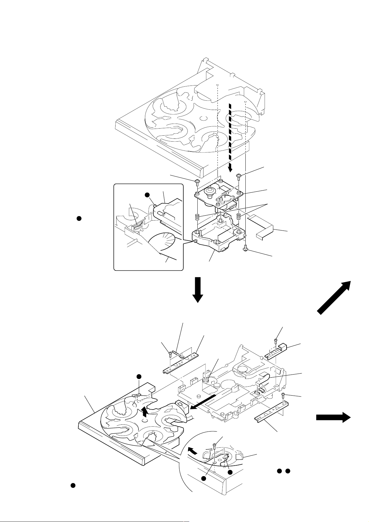
BASE UNIT (BU-5BD32A)
4 two screws
(PTPWH M2.6)
4 two screws
(PTPWH M2.6)
5 base unit (BU-5BD32A)
1 wire (flat type) (21 core)
(CN101)
6 four compression springs (932)
3
2 two screws
(PTPWH M2.6)
7 holder (BU) ass’y
lever (lifter)
BU section
Note: When installing the BU
on the chassis, set the
lever (lifter) in free
position, the gear (U/D)
in UP position, and insert
the shaft into the
groove of gear (U/D).
gear (U/D)
b
b
TABLE ASS’Y
Note: When installing the table ass’y
on the chassis ass’y, engage
the gear (loading C) with the groove
by looking into the gear through
a hole in the table ass’y.
qs table ass’y
e
9 three screws
(BTTP M2.6)
e
q; clamp
3
qa bracket (guide)
gear
(loading C)
2 two screws
(BTTP M2.6)
c
d
7 two screws
(BTTP M2.6)
6 bracket (guide)
1 Slide the tray until the screw
that fixes the bracket (guide)
can be seen through a round
c
hole , in the table ass’y.
d
8 bracket (guide 2)
4 wire (flat type)
(6 core) (CN15)
5 screw
(BTTP M2.6)
7
Page 4

TRAY, BELT (ROTARY), SENSOR BOARD
)
1 screw
(PTPWH M2.6)
2 tray
3 belt (rotary)
5 SENSOR board
BELT (LOADING ), LOADING MOTOR BOARD
4 LOADING MOTOR board
4 two screws
(BTTP M2.6)
3 two screws
(BTTP M2.6)
4 two screws
(BTTP M2.6
1 belt (loading)
2 connector
(CN13)
8
Page 5

ADJUSTING PHASE OF SWING GEAR AND GEAR (U/D)
7 gear (U/D)
8 screw
(PTPWH M2.6)
q; screw
(PTPWH M2.6)
circle mark
circle mark
swing gear
gear (RV)
Fig. A
gear (U/D)
9 gear (RV)
Note: Align swing gear, a circle mark
on the gear (U/D), and the teeth
of gear (RV) to the position
showing in the Fig. A.
Note: Follow the assembly procedure in the numerical order given.
5 stopper washer (FR)
3 Let the swing gear through under the
chassis and engage its dowel
with the groove of rotary encoder.
h
f
g
g
4 Push fully the shaft of shaft gear and
align the hole shape of gear (loading B).
6 screw
(PTPWH M2.6)
2 Install the rotary encoder so that
its groove comes to the position
shown in the figure.
f
1 Insert the shaft gear up to the
position where its shaft comes
out by 5 mm.
f
h
9
Page 6

(3) CHASSIS SECTION
108
108
104
105
CDM59-5BD32A
106
T601
108
US, CND
E
110
AEP, UK, EA, SP
AUS
EA
110
110
111
107
108
101
103
not supplied
102
108
not supplied
108
Ref. No. Part No. Description Remark
101 4-977-591-11 FOOT (F50150S)
* 102 4-978-398-21 CUSHION
103 4-943-687-01 HOLDER, PC BOARD
104 A-4725-005-A MAIN BOARD, COMPLETE (US, CND)
104 A-4725-009-A MAIN BOARD, COMPLETE (AEP, UK, SP, AUS)
110
UK
111
108
108
109
101
102
The components identified by
mark 0 or dotted line with
mark 0 are critical for safety .
Replace only with part number specified.
Ref. No. Part No. Description Remark
109 4-224-878-21 PANEL, BACK (CE345: AEP)
109 4-224-878-31 PANEL, BACK (CE345: UK)
109 4-224-878-41 PANEL, BACK (CE345: AUS)
109 4-224-878-52 PANEL, BACK (CE345: E)
109 4-224-878-61 PANEL, BACK (CE345: SP)
Les composants identifiés par une
marque 0 sont critiques pour la
sécurité.
Ne les remplacer que par une pièce
portant le numéro spécifié.
104 A-4725-010-A MAIN BOARD, COMPLETE (E, EA)
105 1-792-130-11 WIRE (FLAT TYPE) (21 CORE)
106 3-703-249-01 SCREW, S TIGHT, +PTTWH 3X6
107 3-703-571-11 BUSHING (S) (FBS002), CORD (E)
107 4-966-267-11 BUSHING (FBS001), CORD (EXCEPT E)
108 7-685-646-79 SCREW +BVTP 3X8 TYPE2 N-S
109 4-224-877-01 PANEL, BACK (CE245: US)
109 4-224-877-11 PANEL, BACK (CE245: CND)
109 4-224-877-41 PANEL, BACK (CE245: AUS)
109 4-224-878-01 PANEL, BACK (CE345: US)
109 4-224-878-11 PANEL, BACK (CE345: CND)
109 4-224-878-71 PANEL, BACK (CE345: EA)
0 110 1-558-943-41 CORD, POWER (E)
0 110 1-575-651-21 CORD, POWER (AEP, UK, EA, SP)
0 110 1-590-926-11 CORD, POWER (CND)
0 110 1-696-845-11 CORD, POWER (AUS)
0 110 1-783-531-31 CORD, POWER (US)
0 111 1-569-008-31 ADAPTOR, CONVERSION (EA)
0 111 1-770-019-11 ADAPTOR, CONVERSION PLUG 3P (UK)
0 T601 1-435-342-11 TRANSFORMER, POWER (US, CND)
0 T601 1-435-343-11 TRANSFORMER, POWER (AEP, UK, SP, AUS)
0 T601 1-435-344-11 TRANSFORMER, POWER (E, EA)
35
Page 7

(4) CD MECHANISM DECK SECTION-1
(CDM59-5BD32A)
206
210
not supplied
204
203
203
205
206
207
M11
206
208
209
203
202
211
202
not
supplied
202
211
201
202
Ref. No. Part No. Description Remark
201 1-676-245-11 SENSOR BOARD
202 4-218-253-01 SCREW (M2.6), +BTTP
* 203 X-4947-960-1 ROLLER ASSY
204 4-224-602-01 TABLE
205 4-224-617-01 GEAR (RM-E)
206 4-985-672-01 SCREW (+PTPWH M2.6), FLOATING
202
36
Ref. No. Part No. Description Remark
207 4-224-616-01 GEAR (RM-M)
208 4-224-615-01 GEAR (RM-B)
209 4-225-328-01 BELT (ROTARY)
210 4-224-603-01 TRAY
211 4-224-619-01 BRACKET (GUIDE)
M11 A-4672-867-A MOTOR ASSY, ROTARY (TRAY)
Page 8

(5) CD MECHANISM DECK SECTION-2
(CDM59-5BD32A)
263
251
265
260
261
262
266
251
268
269
251
270
not supplied
257
M10
258
259
S200
251
256
264
254
267
251
not supplied
271
272
255
251
251
258
BU-5BD32A
Ref. No. Part No. Description Remark
251 4-985-672-01 SCREW (+PTPWH M2.6), FLOATING
252 X-4952-312-1 HOLDER (BU) ASSY
253 4-959-996-21 SPRING (932), COMPRESSION
254 4-225-885-01 BELT (LOADING)
255 4-225-844-01 GEAR (LOADING A)
256 4-224-613-01 GEAR (SHAFT)
257 1-676-244-11 LOADING MOTOR BOARD
258 4-218-253-01 SCREW (M2.6), +BTTP
259 4-224-607-01 GEAR, SWING
260 4-224-609-01 GEAR (LOADING C)
261 4-224-608-01 COLLAR, SWING
262 4-224-611-01 GEAR (LOADING B)
263 3-016-533-21 WASHER (FR), STOPPER
253
252
Ref. No. Part No. Description Remark
* 264 4-951-619-21 CUSHION (A)
265 4-224-606-01 GEAR (RV)
266 4-224-605-01 GEAR (U/D)
267 X-4952-019-1 PULLEY (A) ASSY, CHUCKING
268 1-471-061-11 MAGNET ASSY
269 4-221-688-01 PULLEY (B), CHUCKING
270 4-224-618-01 LEVER (LIFTER)
271 1-791-930-11 WIRE (FLAT TYPE) (6 CORE)
272 1-676-246-11 JUNCTION BOARD
M10 A-4672-879-A MOTOR ASSY, LOADING
S200 1-418-746-11 ENCODER, ROTARY
253
251
(BU, TABLE ADDRESS DETECT)
37
Page 9

(6) BASE UNIT SECTION
(BU-5BD32A)
306
305
307
M101
308
304
303
302
301
Ref. No. Part No. Description Remark
301 4-951-620-01 SCREW (2.6X8), +BVTP
* 302 A-4724-494-A BD BOARD, COMPLETE
303 4-951-940-41 INSULATOR (BU)
304 4-917-565-01 SHAFT, SLED
0 305 8-848-379-31 OPTICAL PICK-UP KSS-213BA/F-NP
303
M102
309
The components identified by
mark 0 or dotted line with
mark 0 are critical for safety .
Replace only with part number specified.
Ref. No. Part No. Description Remark
307 3-713-786-51 SCREW +P 2X3
308 4-917-567-21 GEAR (M)
309 4-917-564-01 GEAR (P), FLATNESS
M101 X-4917-523-3 MOTOR ASSY (SPINDLE)
M102 X-4917-504-1 MOTOR ASSY (SLED)
Les composants identifiés par une
marque 0 sont critiques pour la
sécurité.
Ne les remplacer que par une pièce
portant le numéro spécifié.
306 1-769-069-11 WIRE (FLAT TYPE) (16 CORE)
38
 Loading...