

Sony CDL1100 Service Manual

SERVICE MANUAL
For Technical Service
SUPPLEMENT-2
File this supplement with the service manual.
SUBJECT :1. ADDITION CDL1100-40 SERIES
CDL1100
(ENG-99001)
The 40 series has been added to the CDL1100. Use this manual together with the service manual already distributed (SUPPLEMENT-1).
MODEL IDENTIFICATION
— SPECIFICATION LABEL —
SONY MODEL NO CDL1100-
CD-ROM LIBRARY
-2 : 20 series
-4 : 40 series
1

OUTLINE AND SPECIFICATIONS OF THE CDL110040 SERIES
The CDL1100-40 series is a CD-ROM library system with two 24X
(MAX) speed drives. It incorporates the compact feature of the
CDL1100-20 series.
The main specifications are as follows.
SPECIFICATIONS
CDL1100-40 series (* indicates the differences from the CDL110020 series.)
Capacity
Number of drives 2
Number of slots 100
Total capacity 65GB
Library Performance
Disc Exchange Time Typ.12.2sec. (average)
Drive Performance
*Sustained Transfer Rate 1800-3600KB (P-CAV)
*Access Time Typ.90ms (average)
Interface
Robotics SCSI-2 single ended
Drives SCSI-2 single ended
Analog Audio Output Stereo mini jack
Async RS-232C
Readable Format
CD-DA
CD-ROM (Mode 1 and Mode 2)
CD-ROM XA (Mode 2 Form 1 and Mode 2 Form 2)
CD-I Ready
CD-Bridge
CD-EXTRA
Video CD
Photo CD (Single and multiple session)
Physical Size
Dimentions (WxHxD) 215x430x435 (mm)
*Weight 14.0Kg
Power Requirements
Line Voltage 120V/230V
Line Frequency 50Hz/60Hz
Power Consumption
*0.33A 120V
*0.17A 230V
T emperature
Operating 5 to 35degC
Relative Humidity
Operating 30 to 80%
2

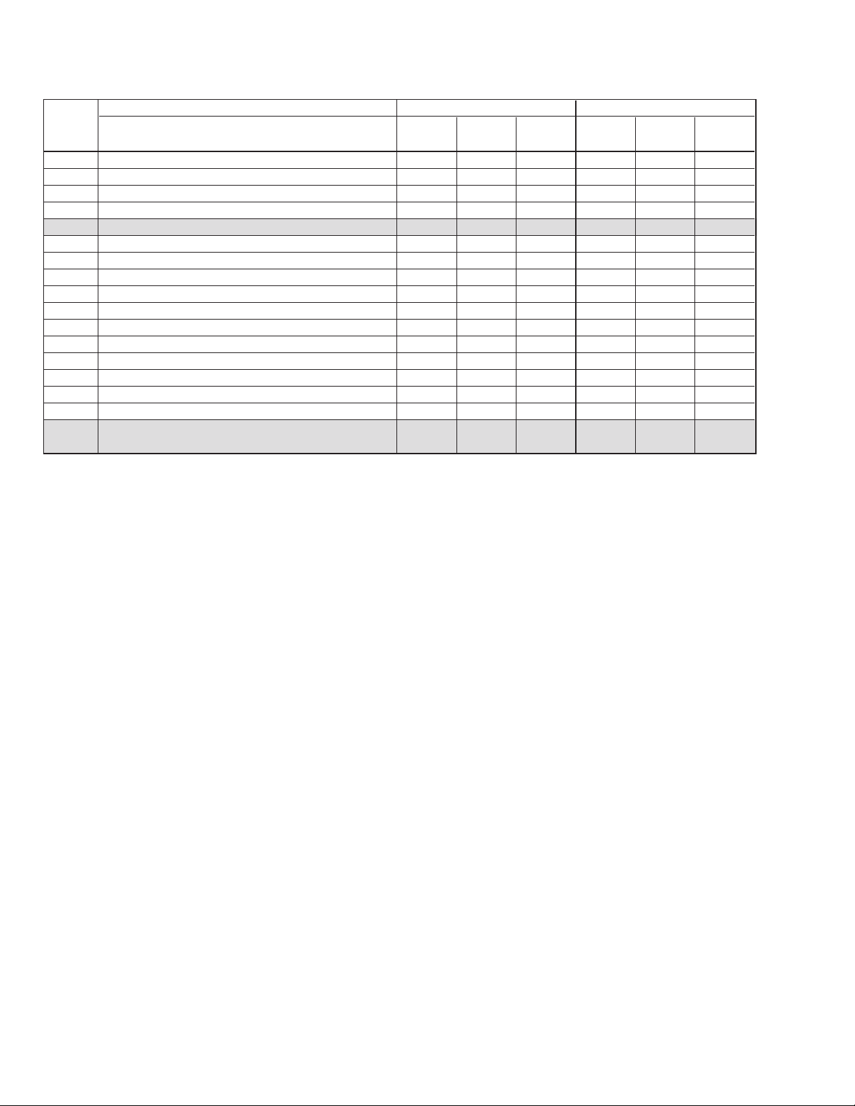
TABLE OF CONTENTS
List of For Primary Service Contents G: Need not refer
Page No: Added, Refer to on page
—: Not applicable
MODEL CDL1100-20 Series CDL1100-40 Series
Section ORIGI- SUPPLE- SUPPLE- ORIGI- SUPPLE- SUPPLE-
List of T ec hnical Service Tools — — 3 — — 3
6 CDM-47/57
6-1 GENERAL 6-1 2 — 6-1 2 —
6-2 T ools and Measuring Instr uments 6-3 — — G —6
6-2-1 Tools and Special Tools List 6-3 — — G —6
6-2-1-1 General T ools 6-3 — — G —6
6-2-1-2 Special T ools 6-3 — — G —6
6-2-1-3 Test Disc 6-3 — — G —6
6-2-1-4 Measuring Equipments G 2—GG 6
6-2-1-5 Software 6-3 — — G —6
6-2-1-6 Expendable and Chemical Supplies 6-3 — — G —6
6-2-2 Setting Single-Operation of CDM-47/57 Mechanism Block 6-4 — — G —7
6-2-3 System Configuration 6-6 — — G —9
6-2-3-1 Set up PS/VS System 6-6 — — G —9
6-2-3-2 System Configuration 6-6 — — G —9
6-3 Trouble Shooting 6-8 — — G —11
6-3-1 Before Trouble Shooting 6-8 — — G —11
6-3-2 Flowchart for Trouble Shooting 6-8 — — G —11
6-3-3 Procedure of ATP Test 6-9 — — G —12
6-3-3-1 Pre-setting 6-9 — — G —12
6-3-3-2 Test Procedure 6-10 — — G —13
6-3-4 Drive Function Check 6-12 — — G —15
6-3-4-1 Pre-setting for T est Mode Operation 6-12 — — G —15
6-3-4-2 Flowchart 6-13 — — G —16
6-3-4-3 Test Command List 6-16 — — G —19
6-3-4-4 Spindle Motor 6-16 — — G —19
6-3-4-5 Sled Gear Train 6-16 — — G —19
6-3-4-6 2-Axis Actuator 6-16 — — G —19
6-3-4-7 Focusing (Focus Bias) 6-16 — — G —19
6-3-4-8 Laser Power 6-16 — — G —19
6-3-4-9 Chucking Mechanism 6-17 — — G —20
6-3-4-10 Sled Motor 6-17 — — G —20
6-3-4-11 Spindle Motor Drive 6-17 —————
6-3-4-12 E-F Balance 6-18 — — G —21
6-3-4-13 RF Level 6-18 — — G —21
6-3-5 Down Load Program 6-20 — — G —23
7 DIAGRAMS
7-1 Circuit Boards Location 7-1 9 — GG25
7-2 IC Pin Function 7-2 — — 7-2 — 26 to 30
7-3 Block Diagrams 7-21 9 — 7-21 9 31, 32
7-4 Frame Schematic Diagram 7-29 9 — 7-29 9 33
7-5 Printed Wir ing Board/Schematic Diagram 7-33 — — 7-33 — 34
Main Section 7-33 10 to 15 — 7-33 10 to 15 —
Power Supply Section 7-40 16 to 20 — 7-40 16 to 20 —
Carrier,Mail Box Section 7-46 21,22 — 7-46 21,22 —
Panel Section 7-52 — — 7-52 — —
CD-ROM Drive Section 7-55 — — G — 34 to 41
EDITION
NAL MENT -1 MENT -2 NAL MENT-1 MENT-2
Continued next page
3
MODEL CDL1100-20 Series CDL1100-40 Series
Section ORIGI- SUPPLE- SUPPLE- ORIGI- SUPPLE- SUPPLE-
7-6 IC Block Diagrams 7-67 — — 7-67 — —
Main Section 7-67 — — 7-67 — —
Power Supply Section 7-69 — — 7-69 — —
CD-ROM Drive Section 7-70 — — G — 42 to 45
8 EXPLODED VIEWS
8-1 Case Section 8-1 G — GG46
8-2 Front Panel Assy Section 8-2 3 — 8-2 3 —
8-3 Chassis Section G 4—G 4—
8-4 Back Panel Section G 23 — G 23 —
8-5 Carrier Assy Section1 8-5 — — 8-5 — —
8-6 Carrier Assy Section2 G 5—G 5—
8-7 Carrier Assy Section3 8-7 — — 8-7 — —
8-8 Disc Case Assy Section 8-8 6 — 8-8 6 —
8-9 Mail Box Assy Section G 7—G 7—
8-10 CDM-47/57 Section 8-10 3 — GG47
8-11 BU Houlder Section 8-11 — G —48
9 ELECTRICAL PARTS LIST
EDITION
NAL MENT -1 MENT -2 NAL MENT-1 MENT-2
9-1
2,3,8,24,
25
—
9-1
2,3,8,
24,25
49 to 52
4

List of Technical Service Tools
Name
Test software-ATP415 system disc (OR-D019)
Test software-ATP625 disc (CDM-001)
Test disc YEDS-18
Test disc TGRS-21
Test disc YEHS-4
DC power supply (Can be substituted with CDL1100)
SCSI 50P Flat Cable
AU-CNBoard
CDL1100 (CDM-47) CONTROLLER
Parts No.
8-980-308-19
J-2501-173-A
3-702-101-01
J-2501-110-A
3-702-548-01
1-413-362-12
J-902-900-0A
A-8080-815-A
J-2501-141-A
CDL1100-20
Series
g
G
g
g
g
g
g
g
g
CDL1100-40
Series
G
g
g
g
G
g
g
g
g
5

6-2. TOOLS AND MEASURING INSTRUMENTS
6-2-1. GENERAL AND SPECIAL TOOLS LIST
The tools and measuring instruments for performing maintenance on
the CDM-47 are listed below.
6-2-1-1. General Tools
SONY Parts No.
⊕Driver 2mm (7-700-749-01)
⊕Driver 2.6mm (7-700-749-03)
T w eezers (7-700-753-02)
Round Nose Plier (7-700-757-01)
Cutter (7-700-758-02)
Soldering Iron (20W)
Desoldering Metal Braid (Solder Wick)
Multi Meter (DRM)
6-2-1-2. Special Tools
IBM PS/VP System
PS/VP and the monitor (640kbyte RAM, 3.5" FDD, HDD, V ideo
RAM-CGA or Higher, DOS Ver. 6.2 or later)
Adaptec SCSI board AHA-1520B or AHA-2940
DC Power Supply (1-413-362-12)
(If no power supply unit is available:Supply power from the
CDL1100 unit.)
Power cord (1-559-370-11)
SCSI 50P Flat Cable (J-902-900-0A)
AU-CN Board (A-8080-815-A)
BLER Counter For TC940X (J-907-564-0A)
CDL1100 (CDM-47) CONTROLLER (J-2501-141-A)
Active Speaker
6-2-1-3. T est Disc
SONY Test Disc (YEDS-18) (3-702-101-01)
SONY Test Disc (TGRS-21) (J-2501-110-A)
6-2-1-4. Measuring Equipments
Oscilloscope Dual Trace 20MHz (probe x10)
DC Volt Meter (min. 10mA)
6-2-1-5. Software
ATP625 Disc (CDM-001) (J-2501-173-A)
6-2-1-6. Expendable and Chemical Supplies
Cotton Swab (200 pieces) (7-740-900-65)
Lens Cleaning Liquid (J-250-100-0A)
Molykote Grease (EM-30L) (4-918-645-01)
Hanarl (SFL-9) (7-400-000-00)
6
6-2-2. Setting Single-Operation of CDM-47 Mechanism
Block
Jig :
CDL-1100 (CDM-47) controller : J-2501-141-A
Power supply unit : 1-413-362-12 (If no power supply units available : Supply power from the CDL1100 unit)
CD test disc (YEDS-18) : 3-702-101-01
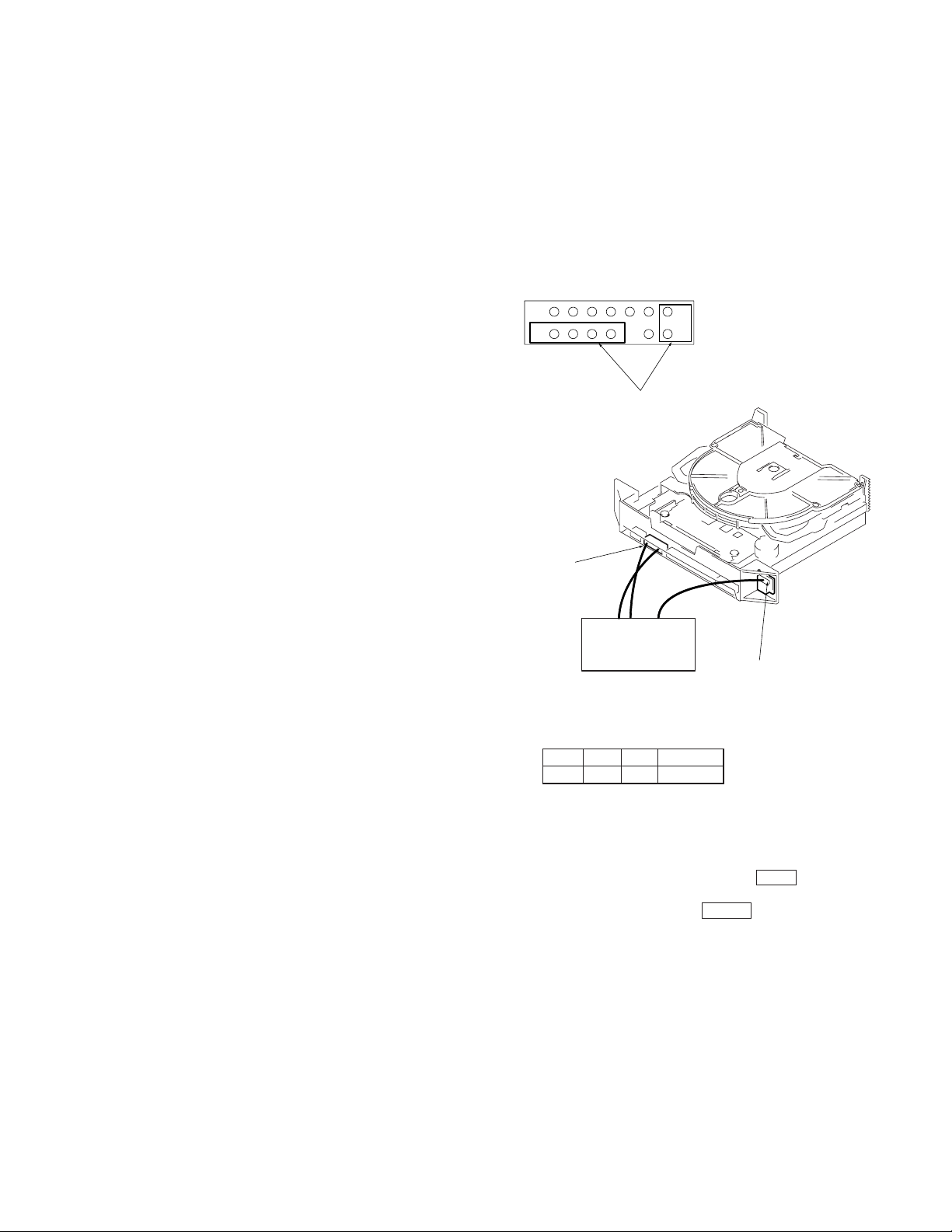
Connection Method :
If no power supply unit is available : Supply power from the CDL1100
unit.
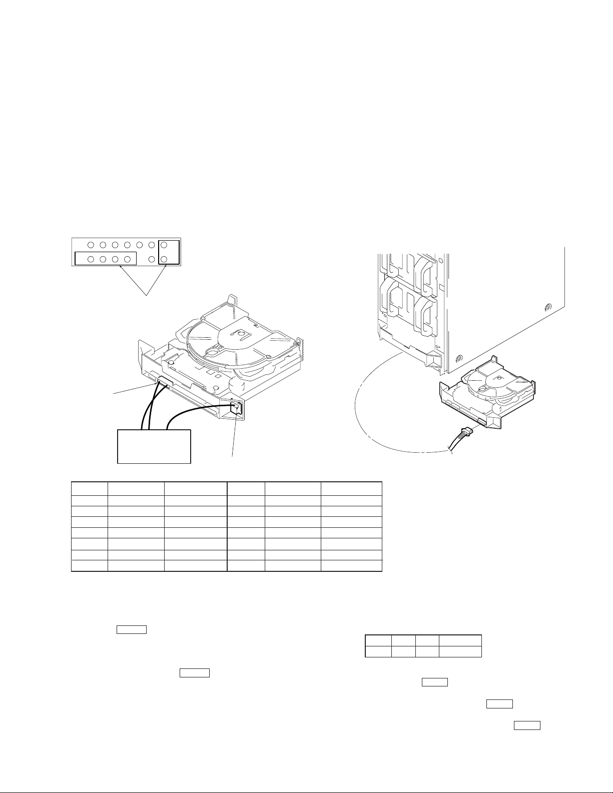
Connect the unit (CNJ202, CN56:MA-C30 board) and controller.
CNJ202 enlargement
7
8
Connect this part to the
controller
CNJ202
(MA-C30 board)
Controller
Pin No.
1
2
3
4
5
6
7
Signal Name
Ground
Ground
Ground
Ground
Ground
Ground
Ground
1
14
CN56 (CN board)
Jig Wire Color
White
—
—
—
—
—
—
Pin No.
8
9
10
11
12
13
14
CDM-47
Signal Name
Parity
ID0
ID1
ID2
NC
P/A
TEST
Supplying power from the CDL1100 unit
CDL1100
CDM-47
CNJ201
Jig Wire Color
Brown
Black
Yellow
Blue
—
—
Red
[Disc Chucking/Unchucking Method]
1. Connect the controller.
2. Load a disc directly into the drive with your hand.
3. Press the EJECT button of the controller. The LEDs will go off
in the order of red and green.
When both LEDs go off, it means that both discs have been
chucked.
4. To eject the disc, press the EJECT button again.
5. The LEDs light up in the order of green and red. When both LEDs
light up, it means that the discs have been unchucked.
NOTE :
If the LEDs remain lit or off even when chucking/unchucking is performed, S51 (red:UNCHUCK), S52 (green:CHUCK) of the CDM47 LDSW board may be improperly connected.
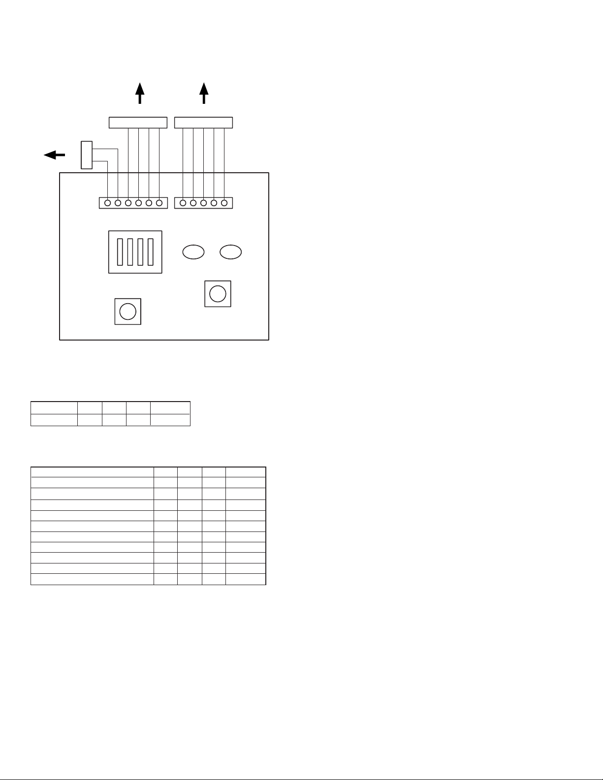
[Single-Operation of CDM-47]
1. Chuck the disc beforehand.
2. Set the COMMAND SW of the controller to the test mode.
ID2LID1HID0LPARITY
L
3. While pressing the TEST button of the controller, turn on the
power of the CDL1100 or power supply unit.
4. After about 1 second later, release the TEST button.
5. This sets the test mode. To enter the other mode, refer to the following table, set the dip switch, and press the TEST button.
7
to CNJ202 to CN56
to CNJ202
White
Red
H
L
COMMAND SW (SW1)
TEST (SW2)
ID2
Blue
ID1
ID0
Yellow
Black
PARITY
Setting of Single-Operation Mode
Mode
Test Mode
ID2
L
ID1
ID0LPARITY
H
Brown
White
UNCHUCK
(RED)
D1
EJECT (SW3)
L
Gray
Gray
Gray
Gray
CHUCK
(GREEN)
D2
Command list of Single-Operation Mode
ID2
Mode
Initialize
x1 speed
x4 speed
x8 speed
x12 –x24(Partial CAV) speed
Tracking servo OFF
Tracking servo ON
PlayAudio (23’47”)
PlayAudio (5’00”)
PlayAudio (55’00”)
ID1
L
L
L
L
L
H
L
H
H
L
L
L
L
L
H
H
H
L
H
H
ID0
L
H
L
H
L
H
L
L
H
H
PARITY
L
L
L
L
L
H
H
L
L
L
8

6-2-3. SYSTEM CONFIGURATION
Setting of SW and Configuration file.
6-2-3-1. Set up PS/VP System
a. Install the ANSI.SYS (Device = ANSI. SYS) and ASPI 2 DOS.SYS
in Config. SYS.
(Refer to Instruction Manual for more detail)
b. Set the jumpers on the Adaptec SCSI Interface board as follows.
(Refer to Instruction Manual for Adaptec SCSI board AHA-1520B
or 2940 in detail)
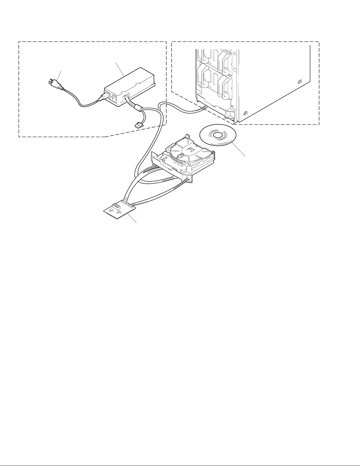
6-2-3-2. System Configuration
PS/VP System
SCSI Interface board
Adaptec AHA-1520B or 2940
AHA-1520B (for ISA BUS)…
All of DIP SW (1 to 4) are OFF.…
AHA-2940 (for PCI BUS)…
No Jumper and SW setting on the board.
Use default parameter for SSI Select configuration utility.
It is not necessary to install the device driver when using on the
windows ’95.
It is necessary to install the device driver a t first line of config. sys
when using on DOS.
c. Install the SCSI Interface board in the PS/VP System.
RCC-015H
ATP625 Disc
Firmware Program Disc
Power Code
SONY T est Disc
(TGRS-21) (for ATP)
Power Supply
AU-CN Mount
(ATAPI)
CDL1100 (CDM-47)
Controller
ATP/DOWNLOAD System
Terminator
Active Speaker
9
Power Cord
Power Supply
SONY T est Disc
(YEDS-18)
CDL1100 (CDM-47)
Controller
Function check
10

6-3. TROUBLE SHOOTING
This section describes trouble shooting methods.
Section 6-3-2. shows the flowchart of the processing routine of the
unit. Section 6-3-3. describes the ATP procedures. These sections
define the detective parts under operating conditions.
6-3-1. BEFORE TROUBLE SHOOTING
The following procedures are recommended to verify if the drive is
really faulty or not:
a. Poor connection with the host system
(esp. GND-related connection, frame GND, etc.)
b. Incorrect operational procedure.
6-3-2. FLOWCHART FOR TROUBLE SHOOTING
START
c. Program error of host system
d. No Interface Cable Terminator at the end of Data Bus
e. Wrong Drive Number selection
f. Wrong supply voltage
g. Environmental conditions (where electrical noise easily jumps into
signal)
h. Influence of strong magnetic field.
(Refer to section 6-3-3.)
ATP
Pass
END
Fail
Optical Pick-up Cleaning
Perform drive
function check
(Refer to section 6-3-4.)
Fail
Part Replacement
Pass
11

6-3-3. PROCEDURE OF ATP TEST
6-3-3-1. Pre-setting
a. Connect the test drive to the PS/VP System. (Refer to 6-2-3-1.)
b. Set the Jumpers on the Adaptec SCSI board. (Refer to 6-2-3-1.)
c. Connect the test drive to the CDL1100 (CDM-47) CONTROL-
LER and set the COMMAND SW as below.
ID2HID1LID0LPARITY
L
d. Connect the test drive to the DC power supply.
e. Turn on the power of PS/VP System.
f. After loading the system, “C >” is displayed on the screen. Then,
insert A TP625 Disc.
Sony SCSI CD-ROM Failure Verification Test Ver. 1.00.02 [MAR. -04-1997]
[ID:7]=ASW-1210 V 3.60 ADAPTEC AHA-1520ADAPTEC AHA-1520
ATP625.CFG X-XXX-XX-XX
00: Inquiry Check
01: TEST UNIT READY
02: TOC Read
03: Incremental Read
04: Random Seek &Read
05: Spin Up/Down (X1)
06: Spin Up/Down (X4)
07: Spin Up/Down (MAX)
08: Full seek Read (X1)
09: 1/3 seek Read (X1)
10: Full seek Read (X4)
11: 1/3 seek Read (X4)
12: Full seek Read (MAX)
13: 1/3 seek Read (MAX)
14: Play Audio (De-TRCK)
15: Play Audio (E-Volume)
16: Play Audio (Play Mode)
17: Play Audio (X’Talk L->R)
18: Play Audio (X’Talk R->L)
19: Sub Code Read
g. Change the directory in the drive A. (“A >” is displayed on the
screen.)
h. Type A T P 6 2 5 and hit Enter key. (After loading the test
program, Display 6-3-3-1. (a) shows up.)
Drive Status Column
Hit any key to start or Esc to exit.
?
12
Display 6-3-3-1. (a)
6-3-3-2. T est Procedure
TEST item
To execute ATP test of the drive.
1. Insert the test disc (TGRS-21) into the CDM-47 drive unit. and
hit any key to start ATP test.
Note:
When some errors occurred during the test, “ A bort R etry I
gnore” message will be displayed i=on the drive status column, at
that time hit A key to exit and then check which part is broken in
accordance with 3-4.
Note:
If each test result satisfies the specification, the word of “Pass” or
value of the test result will be displayed on the judgement column.
a. Inquity check test will be executed.
b. “Returned Data OK ? (Y/N) = >?” message will be displayed
on the drive status column, then check the inquiry data and
hit Y key.
c. When “Place CD-ROM TEST DISC (TGRS-2D)...” is dis-
played, press the EJECT button of the CDL1100 (CDM-47)
controller, and chuck the disc. If the disc has already been
chucked, the display will not be shown, and the unit will pro-
ceed onto the next step.
d. TOC Read test will be executed.
e. Incremental Read Test will be executed.
f. Random Seek & Read test will be executed.
g. Spin Up, Spin Down test (normal) will be executed.
h. Spin Up, Spin Down test (quadruple) will be executed.
i. Spin Up, Spin Down test (Max) will be executed.
j. Full seek test (normal) will be executed.
k. 1/3 seek test (normal) will be executed.
l. Full seek test (quadruple) will be executed.
m. 1/3 seek test (quadruple) will be executed.
n. Full seek test (Max) will be executed.
o. 1/3 seek test (Max) will be executed.
2. After Seek test completion, Play Audio (DeTRCK) test will be
executed.
a. “Hit any key when ready” message will be displayed on the
drive status column, then hit any key.
b. Play Audio (E-Volume) test will be executed.
c. “Any key when Okay or Esc when NG” message will be dis-
played on the drive status column, then hit any key.
d. Play Audio (Play Mode) test will be executed.
e. “Space bar when ready, ESC to abort” message will be dis-
played on drive status column, then hit space bar.
f. Play Audio (X’Talk LnR) test will be executed.
g. “ Any k ey when Okay or Esc when NG” message will be dis-
played on drive status column, then hit any key.
h. Play Audio (X’Talk RnL) test will be executed.
i. “ Any k ey when Okay or Esc when NG” message will be dis-
played on drive status column, then hit any key.
3. After Audio test completion, Sub Code Read test will be executed.
Check point
The music (both left and right channel) can be heard from the active speaker.
The music (both left and right channel) will be faded-out slowly.
(After several minutes, the drive is set to mute mode.)
The music (both left and right channel) can be heard from the active speaker. And the play mode can be changed by pushing some
key.
(Refer to Drive Status Column)
The sound (only left channel) can be heard for 3 sec. from the active speaker.
The sound (only lright channel) can be heard for 3 sec. from the
active speaker.
13

TEST item
Check point
Note:
If all of test items are completed, words of OK will be displayed on
the screen.If not, NG will be displayed.
Sony SCSI CD-ROM Failure Verification Test Ver. 1.00.00 [Nov. -22-1996]
[ID:7]=ASW-1210 V 3.60 ADAPTEC AHA-1520ADAPTEC AHA-1520
ATP625.CFG
00: Inquiry check [ Pass ] [ ID:3 ]=SONY CD-ROM CDU625 X.Xx
01: TEST UNIT READY [ Pass ] READY
02: TOC read [ Pass ]
03: Incremental Read [ Pass ]
04: Random Seek & Read
05: Spin Up/Down (X1) [ Pass ] Spin Up : XXXX [ms] Spin Down : XXX [ms]
06: Spin Up/Down (X4) [ Pass ] Spin Up : XXXX [ms] Spin Down : XXX [ms]
07: Spin Up/Down (Max) [ Pass ] Spin Up : XXXX [ms] Spin Down : XXXX [ms]
08: Full seek Read (X1) [ Pass ] Max : XXXX [ms] Ave : XXXX [ms]
09: 1/3 seek Read (X1) [ Pass ] Max : XXXX [ms] Ave : XXXX [ms]
10: Full seek Read (X4) [ Pass ] Max : XXXX [ms] Ave : XXXX [ms]
11: 1/3 seek Read (X4) [ Pass ] Max : XXXX [ms] Ave : XXXX [ms]
12: Full seek Read (Max) [ Pass ] Max : XXXX [ms] Ave : XXXX [ms]
13: 1/3 seek Read (Max) [ Pass ] Max : XXXX [ms] Ave : XXXX [ms]
14: Play Audio (DeTRCK) [ Pass ]
15: Play Audio (E-Volume) [ Pass ]
16: Play Audio (Play Mode) [ Pass ]
17: Play Audio (X’Talk L->R) [ Pass ]
18: Play Audio (X’Talk R->L) [ Pass ]
19: Sub Code Read [ Pass ]
Remove the DISC Hit any key when ready
OK
The disc will automatically be unchucked.
Sony SCSI CD-ROM Failure Verification Test Ver. 1.00.00 [Nov. -22-1996]
[ID:7]=ASW-1210 V 3.60 ADAPTEC AHA-1520ADAPTEC AHA-1520
ATP625.CFG
0: Inquiry check [ Pass ] [ ID:3 ]=SONY CD-ROM CDU625 X.Xx
1: TEST UNIT READY [ Pass ] READY
2: TOC read [ Pass ]
3: Incremental Read [ Pass ]
4: Random Seek & Read
5: Spin Up/Down (X1) [ Pass ] Spin Up : XXXX [ms] Spin Down : XXX [ms]
6: Spin Up/Down (X4) [ Pass ] Spin Up : XXXX [ms] Spin Down : XXX [ms]
7: Spin Up/Down (Max) [ Pass ] Spin Up : XXXX [ms] Spin Down : XXXX [ms]
8: Full seek Read (X1) [ Pass ] Max : XXXX [ms] Ave : XXXX [ms]
9: 1/3 seek Read (X1) [ Pass ] Max : XXXX [ms] Ave : XXXX [ms]
10: Full seek Read (X4) [ Pass ] Max : XXXX [ms] Ave : XXXX [ms]
11: 1/3 seek Read (X4) [ Pass ] Max : XXXX [ms] Ave : XXXX [ms]
12: Full seek Read (Max) [ Pass ] Max : XXXX [ms] Ave : XXXX [ms]
13: 1/3 seek Read (Max) [ Pass ] Max : XXXX [ms] Ave : XXXX [ms]
14: Play Audio (DeTRCK) [ Pass ]
15: Play Audio (E-Volume) [ Pass ]
16: Play Audio (Play Mode) [ Pass ]
17: Play Audio (X’Talk L->R) [ Pass ]
18: Play Audio (X’Talk R->L) [ Pass ]
19: Sub Code Read [ Pass ]
Remove the DISC Hit any key when ready
NG
14
6-3-4. DRIVE FUNCTION CHECK
6-3-4-1. Pre-Setting for Test Mode Operation
Since CDM-47 models is adjustment-free drive, there is no potentiometer fo electrical adjustment in the MA-C30 Mounted Board. Therefore BU or MA Mounted Board can be swapped over without any
manual adjustment so that you will easily find defective components
(if the trouble depends on BU or MA Mounted Board). (Refer to 6-34-2.)
Note: All of adjustment items, will be automatically performed after
power-on by the function of CD DSP IC.
The page 6-15 shows the sequence of execution items in Po werOn Reset Actions. It will help you finding any defective point
on the drive to know the specified processing sequence of the
auto adjustment items and drive’s action in the Power-On Reset Actions.
Preparing
a. The following tools and measuring equipments are necessary for
performing this section.
DC Power Supply or CDL1100 unit
Oscilloscope
Sony Test Disc (YEDS-18) (3-702-101-01)
CDL1100 (CDM-47) CONTROLLER (J-2501-141-A)
b. Connect the test drive to the DC power supply or CDL1100 unit.
Note: This section is performed only specified following sections.
Note: This section describes usages of Test Mode Operation and sig-
nal checking on the CDM-47 drives with the CDL1100 (CDM-
47) CONTROLLER.
a. Connect CDM-47 to CDL1100 (CDM-47) CONTROLLER as
shown in following Fig. 3-4-1.
CNJ202 enlargement
7
8
Connect this part to the
controller
CNJ202
(MA-C30 board)
1
14
CDM-47
Controller
CN56 (CN board)
b. See the COMMAND SW ON CDL1100 (CDM-47) CONTROL-
LER as following table.
ID2LID1HID0LPARITY
L
c. While pressing the TEST button of the controller, turn on the
power of the CDL1100 or power supply unit.
d. After about 1 second later, release the TEST button.
Note: Even drive is Test Mode, EJECT button is activated.
15

6-3-4-2. Flowchart
Note: These flowchart is described assuming that IC failure causes any trouble.
Start
Mechanical or Electrical trouble ?
Electrical
Nothing in action in Power-On ?
Proceeding Adjustment Action
BU/Main PWB/HP PWB
dependent ?
(check by swapping BU or PWBs.)
Main PWB dependent
Power-On Reset actions Completes or
Failed/action NG ?
Completed
Mechanical
No action
BU dependent
HP PWB dependent
Failed /NG
Mechanical Checking/Repairing
IC303 (CPU) failure
IC305 (gate-array) failure
IC304 (Flash-ROM) failure
BU/OP checking/Replace BU
HP PWB checking
IC201 (CD DSP/servo IC) failure
IC101 (RF Amp IC) failure
Drive ICs failure
SCSI command execution
communication OK or NG ?
(check with any SCSI command)
OK
Read Operation
OK
End
Flowchart (1) Repairing/Trouble Shooting-General
NG
Access Time NG
Read Data Error
Refer to Flowchart (2)-Power-on Reset Actions
IC301 (CDROM/SCSI I/F IC) failure
IC304 (Flash-ROM) failure
IC201 (CD DSP/servo IC) failure
Motor Driver ICs failure
IC301 (CDROM/SCSI I/F IC) failure
IC302 (buffer RAM) failure
16

Power on Reset Action
Failed/Action NG
Retry for detailed checking
Trouble/Failed in Step (2)-(11)
(Spin-up/Focus-on)
OK/Passed
Trouble/Failed in Step (12)-(15)
(Auto Adjustment Functions)
OK/Passed
Trouble/Failed in Step (16)-(21)
(Read TOC/Set x8 speed)
OK/Passed
OK/Completed
(Try Read operation)
NG
NG
NG
Focus Search (Refer to 6-3-4-6.)
Spindle Motor Driver IC (Refer to 6-3-4-11.)
RF Signal (Refer to 6-3-4-13.)
Check Focus/Tracking Servo Error Signal
RF Signal (Refer to 6-3-4-13.)
RF Signal (Refer to 6-3-4-13.)
Spindle Motor Driver IC (Refer to 6-3-4-11.)
IC101
IC201
IC106
IC101
IC201
IC101
IC106
Flowchart (2) Repairing/Trouble Shooting-Power-on Reset Actions
17
 Loading...