

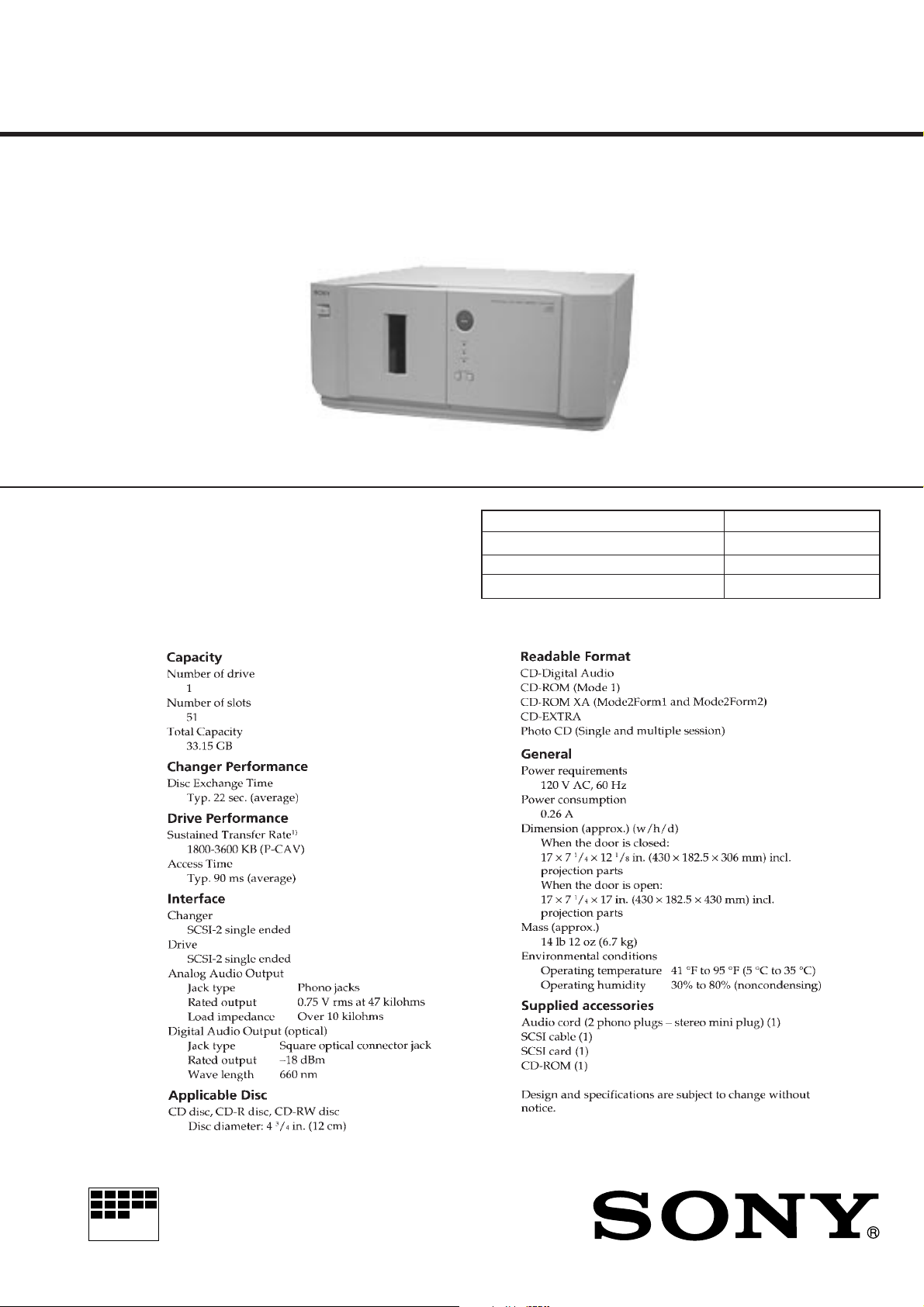
CDJ-500
SERVICE MANUAL
Model Name Using Similar Mechanism NEW
CD Mechanism Type CDM-56
Base Unit Type BU-24
Optical Pick-up Type SPU3212
SPECIFICATIONS
US Model
Canadian Model
MICROFILM
CD-ROM CHANGER
Laser component in this product is capable of emitting radiation
exceeding the limit for Class 1.
This appliance is classified as
a CLASS 1 LASER product.
The CLASS 1 LASER PRODUCT MARKING is located on
the rear exterior.
CAUTION
Use of controls or adjustments or performance of procedures
other than those specified herein may result in hazardous radiation exposure.
Notes on chip component replacement
• Never reuse a disconnected chip component.
• Notice that the minus side of a tantalum capacitor may be
damaged by heat.
Flexible Circuit Board Repairing
• Keep the temperature of soldering iron around 270˚C
during repairing.
• Do not touch the soldering iron on the same conductor of the
circuit board (within 3 times).
• Be careful not to apply force on the conductor when soldering
or unsoldering.
SAFETY CHECK-OUT
After correcting the original service problem, perform the following safety checks before releasing the set to the customer:
Check the antenna terminals, metal trim, “metallized” knobs, screws,
and all other exposed metal parts for AC leakage. Check leakage as
described below.
LEAKAGE
The AC leakage from any exposed metal part to earth Ground and
from all exposed metal parts to any exposed metal part having a
return to chassis, must not exceed 0.5 mA (500 microampers). Leakage current can be measured by any one of three methods.
1. A commercial leakage tester, such as the Simpson 229 or RCA
WT-540A. Follow the manufacturers’ instructions to use these
instruments.
2. A battery-operated AC milliammeter. The Data Precision 245
digital multimeter is suitable for this job.
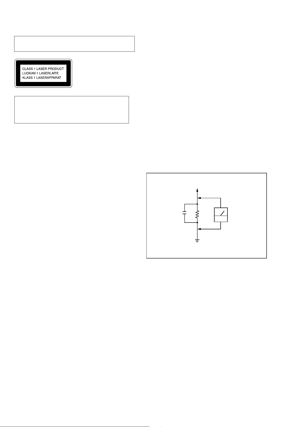
3. Measuring the voltage drop across a resistor by means of a VOM
or battery-operated A C v oltmeter. The “limit” indication is 0.75
V, so analog meters must have an accurate low-voltage scale.
The Simpson 250 and Sanwa SH-63Trd are examples of a passive VOM that is suitable. Nearly all battery operated digital
multimeters that have a 2V AC range are suitable. (See Fig. A)
To Exposed Metal
Parts on Set
SAFETY-RELATED COMPONENT WARNING !!
COMPONENTS IDENTIFIED BY MARK ! OR DO TTED LINE
WITH MARK ! ON THE SCHEMATIC DIAGRAMS AND IN
THE PARTS LIST ARE CRITICAL TO SAFE OPERATION.
REPLACE THESE COMPONENTS WITH SONY PARTS
WHOSE PART NUMBERS APPEAR AS SHOWN IN THIS
MANUAL OR IN SUPPLEMENTS PUBLISHED BY SONY.
ATTENTION AU COMPOSANT AYANT RAPPORT
À LA SÉCURITÉ!!
LES COMPOSANTS IDENTIFIÉS P AR UNE MARQUE ! SUR
LES DIAGRAMMES SCHÉMATIQUES ET LA LISTE DES
PIÈCES SONT CRITIQUES POUR LA SÉCURITÉ DE
FONCTIONNEMENT . NE REMPLA CER CES COMPOSANTS
QUE PAR DES PIÈCES SONY DONT LES NUMÉROS
SONT DONNÉS DANS CE MANUEL OU DANS LES
SUPPLÉMENTS PUBLIÉS PAR SONY.
0.15µF
1.5k
Earth Ground
Ω
AC
voltmeter
(0.75V)
Fig. A. Using an AC voltmeter to check AC leakage.
2

TABLE OF CONTENTS
1. SERVICE NOTE ................................................................ 4
2. GENERAL ......................................................................... 29
3. DISASSEMBLY
3-1. Front Panel ......................................................................... 30
3-2. Illumination Assy................................................................31
3-3. CD Mechanism Deck..........................................................31
3-4. Base Unit and Magnet Holder............................................. 32
3-5. CD Mechanism Section ...................................................... 33
4. MECHANICAL ADJUSTMENTS
4-1. Disc Holder a Adjustment/Chucking Pulley
Position Adjustment ............................................................ 34
4-2. Disc Sensor Adjustment ...................................................... 36
5. ELECTRICAL ADJUSTMENTS
5-1. Tools and Measuring Instruments ....................................... 37
5-2. Trouble Shooting.................................................................40
6. THEORY OF OPERATION........................................... 52
7. DIAGRAMS
7-1. Circuit Boards Location......................................................53
7-2. Block Diagrams
• CD-ROM Drive (1/2) Section...........................................54
• CD-ROM Drive (2/2) Section...........................................55
• Main Section.....................................................................56
• Power Supply Section....................................................... 57
7-3. Printed Wiring Board – CD-ROM Drive Section – ............58
7-4. Printed Wiring Board – CD-ROM Drive Section –............. 59
7-5. Schematic Diagram – CD-ROM Drive (1/6) Section – ...... 60
7-6. Schematic Diagram – CD-ROM Drive (2/6) Section – ...... 61
7-7. Schematic Diagram – CD-ROM Drive (3/6) Section – ...... 62
7-8. Schematic Diagram – CD-ROM Drive (4/6) Section – ...... 63
7-9. Schematic Diagram – CD-ROM Drive (5/6) Section – ...... 64
7-10. Schematic Diagram – CD-ROM Drive (6/6) Section –..... 65
7-11. Schematic Diagram – Main Section –............................... 66
7-12. Printed Wiring Board – Main Section – ............................ 67
7-13. Schematic Diagram – Panel Section – .............................. 68
7-14. Printed Wiring Board – Panel Section –............................ 69
7-15. Schematic Diagram – Sensor Section – ............................ 70
7-16. Printed Wiring Board – Sensor Section – ......................... 71
7-17. Schematic Diagram – SCSI Section –............................... 72
7-18. Printed Wiring Board – SCSI Section – ............................ 73
7-19. Schematic Diagram – Power Section – ............................. 74
7-20. Printed Wiring Board – Power Section – .......................... 75
7-21. IC Block Diagrams............................................................ 76
7-22. IC Pin Functions................................................................ 83
8. EXPLODED VIEWS
8-1. Case Section ........................................................................ 90
8-2. Front Panel Section ............................................................. 91
8-3. Chassis Section ................................................................... 92
8-4. Mechanism Deck Section-1 (CDM-56) .............................. 93
8-5. Mechanism Deck Section-2 (CDM-56) .............................. 94
8-6. Base Unit Section................................................................ 95
9. ELECTRICAL PARTS LIST ........................................ 96
3
SECTION 1
SERVICE NOTE
LOADING IN/OUT AGING
Loading in and loading out are repeatedly carried out in this aging
mode.
Operations are stopped when an error occurs. (When loading in or
loading out took more than 6 seconds.)
Procedure:
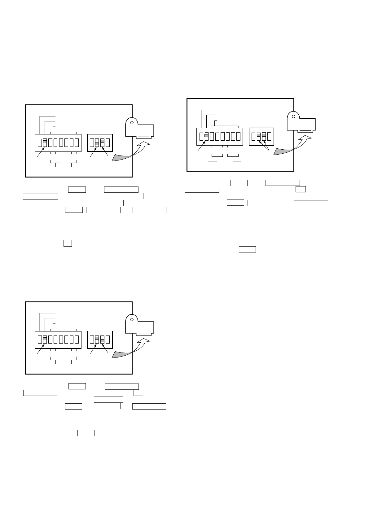
1. Set the DIP switches on the back panel as shown below.
SCSI TERM
MODE
ID SELECT
2
ON
DRIVE
4
2
4
1
1
CHANGER
OFF
ON
Remove the
shield.
2. While pressing the OPEN button, DISC SKIP – button, and
DISC SKIP + button simultaneously, press the U button to
turn ON the power. When the CHANGER indicator starts to
blink, release the OPEN , DISC SKIP – and DISC SKIP +
buttons.
3. The front door opens automatically. Set one disc in any slot.
4. Close the front door.
5. Loading in and loading out of the disc are repeated.
6. To end, press the U button to turn OFF the power.
DISC TABLE AGING
* This mode is used for operating the disc table randomly.
Operations will continue unless an error occur.
TOTAL AGING
This mode is used for executing loading in and loading out of discs
in any slits sequentially.
Operations are stopped when an error occurs.
Procedure:
1. Set the DIP switches on the back panel as shown below.
SCSI TERM
MODE
ID SELECT
2
4
ON
DRIVE
2. While pressing the OPEN button, DISC SKIP – button, and
DISC SKIP + button simultaneously, press the U button to
turn ON the power. When the CHANGER indicator starts to
blink, release the OPEN , DISC SKIP – and DISC SKIP +
buttons.
3. The front door opens automatically. Set discs in any slot.
4. Close the front door to start aging.
5. During aging, operations are repeated in the order of “rotation
of disc table” n ”loading in” n ”disc access” n ”loading
out” n ”rotation of disc table”.
6. To end aging, press the OPEN button .
2
4
1
1
CHANGER
ON
Remove the
shield.
Procedure:
1. Set the DIP switches on the back panel as shown below.
SCSI TERM
MODE
ID SELECT
2
ON
DRIVE
4
2
4
1
1
CHANGER
ON
OFF
Remove the
shield.
2. While pressing the OPEN button, DISC SKIP – button, and
DISC SKIP + button simultaneously, press the U button to
turn ON the power. When the CHANGER indicator starts to
blink, release the OPEN , DISC SKIP – and DISC SKIP +
buttons.
3. The front door opens automatically.
4. Close the front door to start aging.
5. To end aging, press the OPEN button.
4
CHECKING OPERA TIONS USING THE FIELD50.EXE
h
PROGRAM
• When this program is executed, the operations of each part are
checked so that faulty parts can be investigated during repairs.
It is recommended that this program is executed before returning
the unit to the customer after completing repairs and that all test
items are checked that they are satisfactory.
An instruction manual in PDF file format describing the details is
provided with the program file. Refer to this manual for further
details.
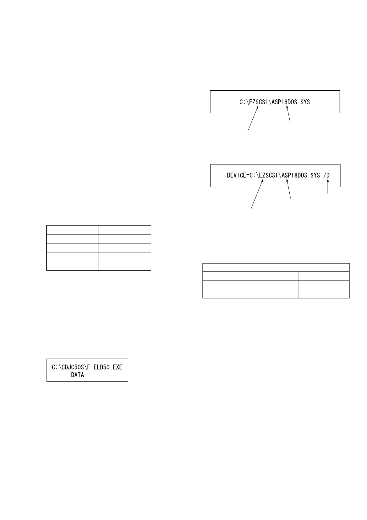
Installing the “ASPI manager”:
1. Create the desired directory in the C drive. The “EZSCSI” directory is explained here as an example.
2. Copy the file of the ASPI manager corresponding to the directory created in step 1. The “ASPI8DOS.SYS” file is explained
here as an example.
Preparations:
• IBM PC compatible Personal computer and display:
Use a personal computer with an HDD
• OS;
MS-DOS or PC-DOS version 5.0 or later.
• Floppy disk with latest “FIELD50.EXE” software (Includes the
instruction manual (FIELD50.PDF)) (CDJ-001:J-2501-172-A)
• SCSI board;
The “Adaptec AVA-2904E” provided with the unit is recommended. If this is not available, use an equivalent.
• Setting the ASPI manager
Install the “ASPI manager” suitable for the SCSI board, and rewrite the “CONFIG. SYS” file. (Refer to the following procedure.)
ASPI managers (In the case of Adaptec products)
SCSI Board ASPI Manager
AVA-2904E Aspi8dos. sys
AHA-1510B Aspi2dos. sys
AHA-1542CF Aspi4dos. sys
AHA-2940AU Aspi8dos. sys
• General CD-ROM
• SONY test disc (TGRS-21: Green disc) (J-2501-110-A)
• SCSI cable
• Speakers with amplifier or equivalent. (Use only when checking
the AUDIO output)
File copied at item 2.
Directory created at item 1.
3. Edit the “CONFIG.SYS” file and add the device so that the f ile
copied at 2 is referred to.
Add the /D switc
File copied at item 2.
Directory created at item 1.
Note:
ASPI manager version
Operations of the “FIELD50.EXE” program are guaranteed when
the following ASPI manager version is used. Operations using other
ASPI managers are not guaranteed.
ASPI manager Usable Version
Aspi2dos. sys 3.661J 3.68 3.68s ------Aspi4dos. sys 3.34 3.35 3.36s 3.36s
Aspi8dos. sys 1.26 1.32 1.32s 1.32s
Installing the “FIELD50.EXE”:
1. Create the directory “CDJC50S” in the C drive of the PC used,
and copy the “FIELD50.EXE” file there.
2. Create another directory “DATA” in the directory created in step
1.
5
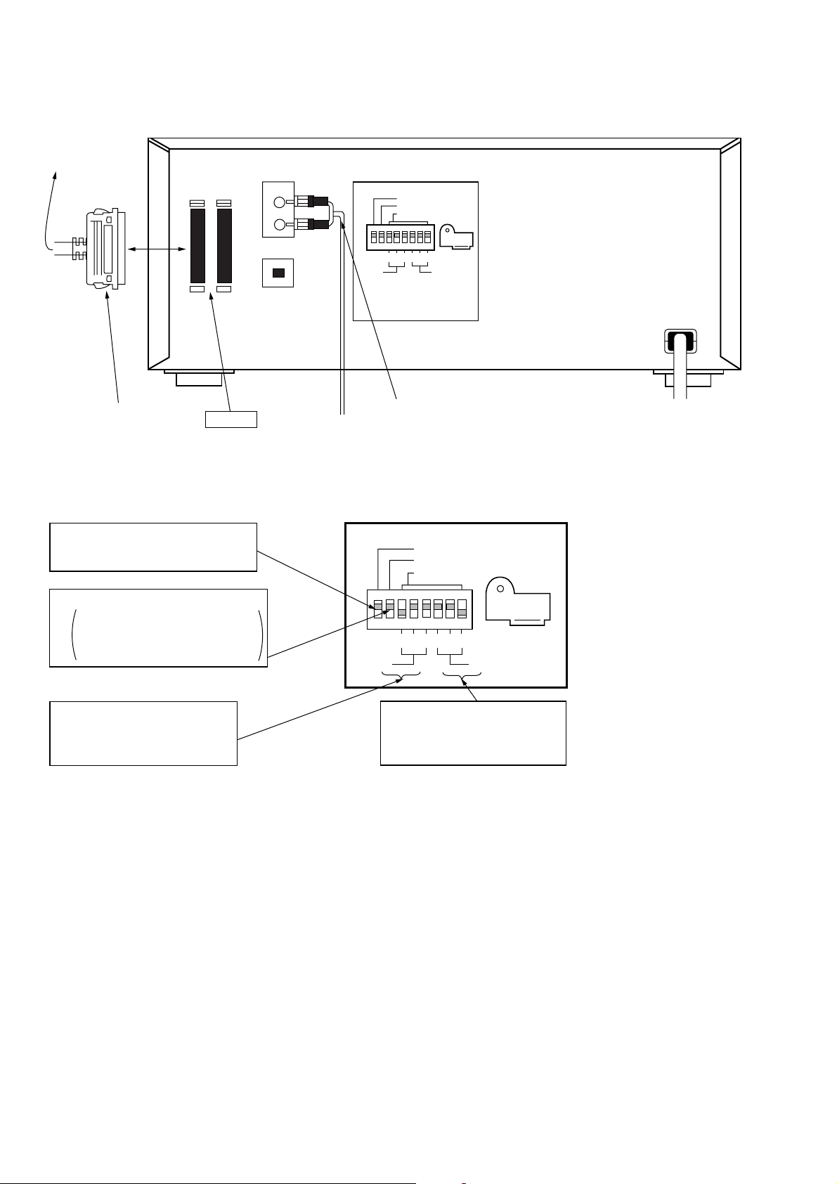
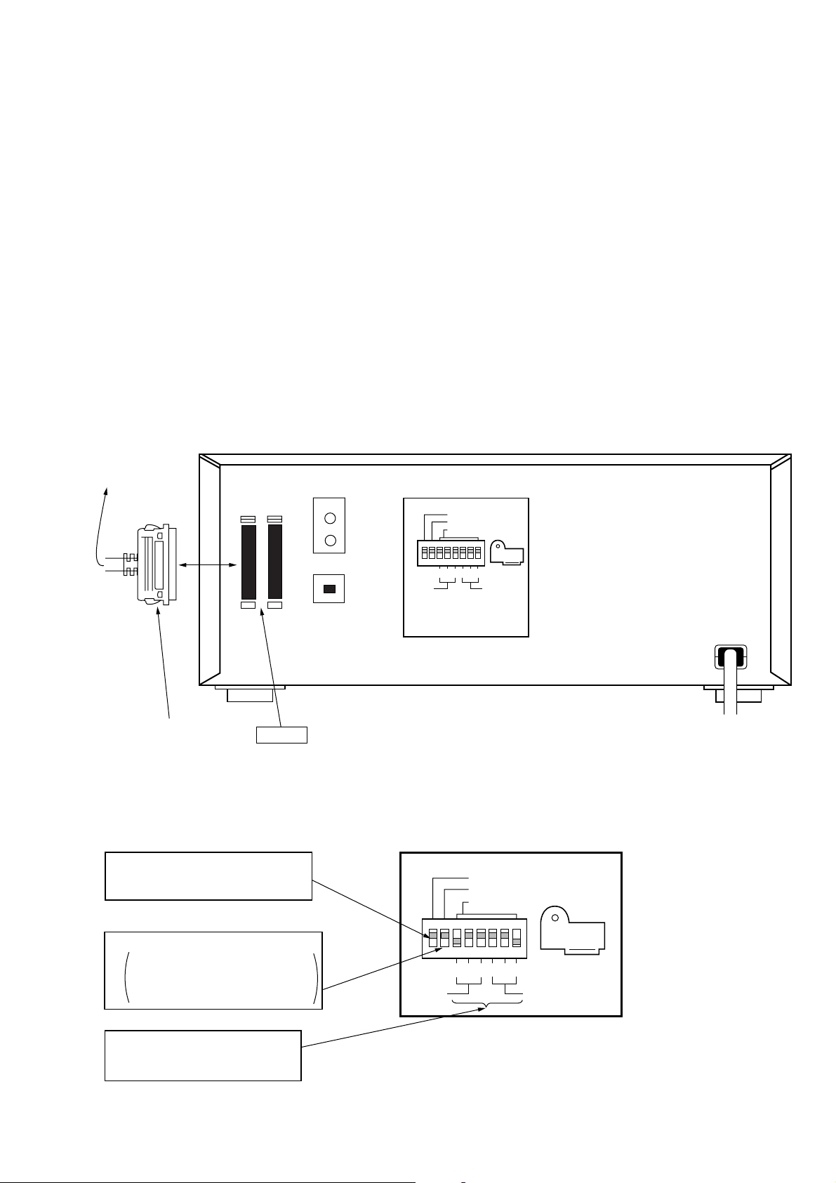
Connection
Connected to
SCSI connector
of the PC
SCSI
IN OUT
ANALOG-OUT
SCSI TERM
MODE
ID SELECT
SCSI cable (Accessory)
SCSI IN
Setting
• DIP switch settings
1 Set SCSI TERM to “ON”, and do not
connect other SCSI equipment as much
as possible.
2 Set MODE to “ON”.
ON: Normal mode. Control the changer
using the PC.
OFF: Manual mode. Control the changer
manually using buttons.
DIGITAL-OUT
2
4
2
4
1
1
DRIVE
CHANGER
Connected to active speaker, etc.
(only when checking the audio output)
Fig. Connection of equipment
SCSI TERM
MODE
ID SELECT
2
4
DRIVE
2
4
1
1
CHANGER
3 Setting of SCSI ID of the drive
Set a desired ID number except 7.
Be careful not to use an ID number
already in use for the changer.
4 Setting of SCSI ID of the changer
Set a desired ID number except 7.
Be careful not to use an ID number
already in use for the drive.
Fig. DIP Switch Setting
6
Operating procedure:
Note:
Operations of this program are not guaranteed when used in the
DOS prompt mode with starting up Windows.
Refer to the instruction manual of the PC used, set the DOS prompt
mode, and execute the program.
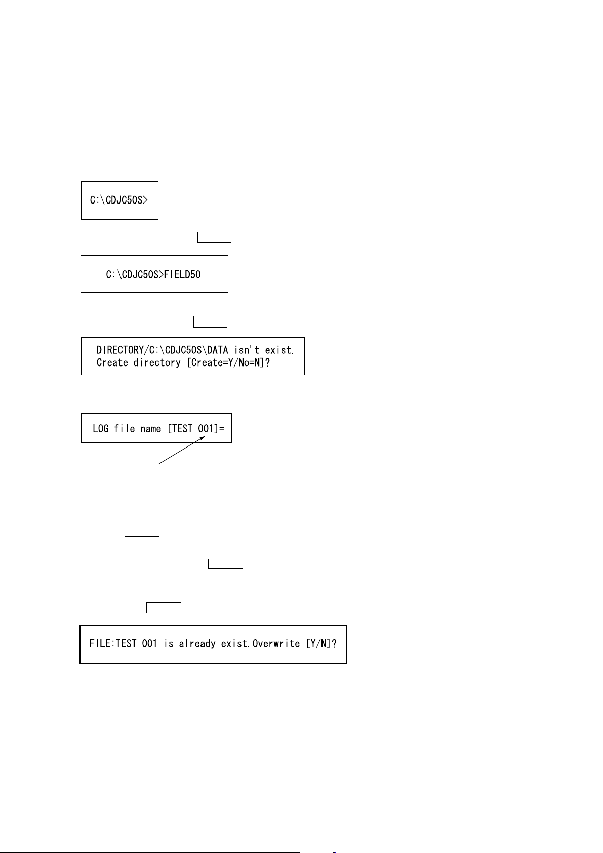
1. Turn on the power of the PC and set the DOS prompt mode.
2. Change the directory to “CDJC50S”.
3. Enter “FIELD50” and press the ENTER key.”
4. If directory for storing the data is not available, enter “Y” at the
following screen and press the ENTER key.
5. The following screen appears.
Default file name
(Suffix number of file name will increase automatically)
Enter a desired file name using less than 8 characters.
(If numbers are used for the suffix of the file name, these will be
counted up automatically the next time.)
When only the ENTER key is pressed, the default file name will
be set.
This file will be saved as the log file in the directory “DATA”.
After entering the file name, press the ENTER key.
6. If a file name already used once is specified, the following screen
appears. Enter “Y” or “N” according to whether to overwrite the
file, and press the ENTER key.
7
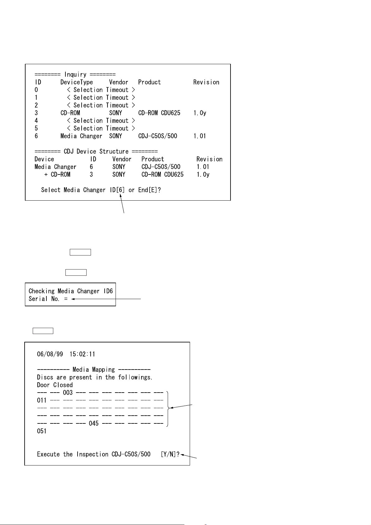
The following screen appears when the file name is not already in
use.
The SCSI ID of the changer detected is displayed as the default value.
For example, as the ID of the changer is set to “6” and the ID of the
drive is set to “3”, these values will be displayed.
Enter “6” for the ID of the media changer to be checked using this
program, and press the ENTER key.
7. The following screen appears. Enter the serial number of the
unit and press the ENTER key.
Enter the serial number of the unit.
8. The number of the slot set with a disc will be displayed. The
screen asks whether the inspection is started. Enter “Y” and press
the ENTER key.
Displays the slot number (s) holding a disc.
(If all slots are empty, — will be displayed.)
Enter Y.
8
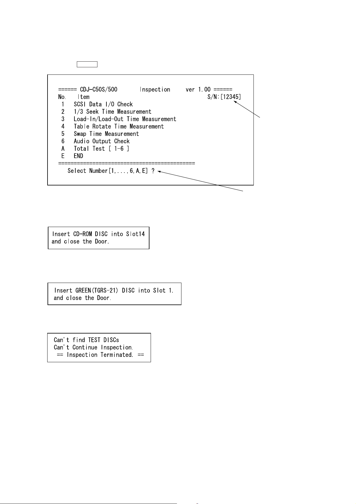
9. The following screen appears. These inspection items can be
d
excuted one by one. The following describes the e xample of executing all the tests. Enter “ A” to execute all the inspection items
and press the ENTER key.
10. The following screen appears and the front door opens automatically. Insert the general CD-ROM into the 14th slot, and
close the door.
Serial number entere
Enter “A”.
11. The following screen appears and the front door opens automatically. Insert the SONY test disc (TGRS-21: Gr een disc) in
the 1st slot, and close the door.
Take note that if the door is closed without inserting any disc, the
following screen appears and tests end.
9
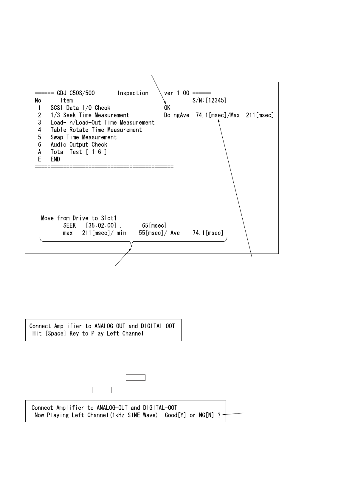
12. When the inspections are executed, the status will be displayed
at the bottom of the screen. The results of each inspection will
be displayed on the right side of the screen.
The results of the inspection will be displayed as OK or NG.
The status of the inspection currently performed are displayed at real-time.
13. The following appears at the bottom of the screen. Check the
audio signal here. During this test, analog audio signals are output from the AN ALOG OUT and digital audio signals from the
DIGITAL OUT.
Check the sounds according to the instructions on the screen.
After completing preparations to check the sounds, press the
space key.
14. When the following screen appears, the 1 KHz sine wave is
output from the L-CH. Enter “Y” and press the ENTER key if
OK. If no sounds are produced from the L-CH or produced from
R-CH, enter “N” and press the ENTER key for negative.
The value of the test results will be displayed.
After checking, enter “Y” or “N”.
10
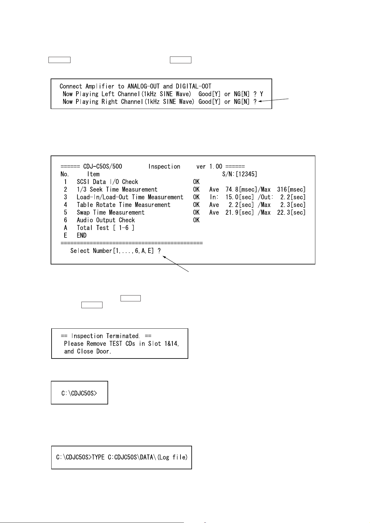
15. The following screen appears at the bottom, and 1 KHz sine
wave is out put from the R-CH. If OK, enter “Y” and press the
ENTER key. Like in step 14, enter “N” and press the ENTER
key if negative.
16. The following screen appears and the results of each test are
displayed.
If the test results are satisfactory, “OK” will be displayed. For
details on the test results, refer to the PDF file provided with
the “FIELD50.EXE” software.
After checking, enter “Y” or “N”.
To end, enter “E”, or to continue, enter the corresponding number.
17. If there is a inspection to be executed again, enter the corresponding number and press the ENTER key . To end, enter “E”
and press the ENTER key.
18. The following screen appears at the bottom left of the screen.
Remove the disc and close the front door.
19. The program is completed, and the following will be displayed.
Referring to the Log File:
• The results executing “FIELD50.EXE” are stored as the log file.
This file is the file name entered at step 5. To see this file on the
screen, enter the following:
11
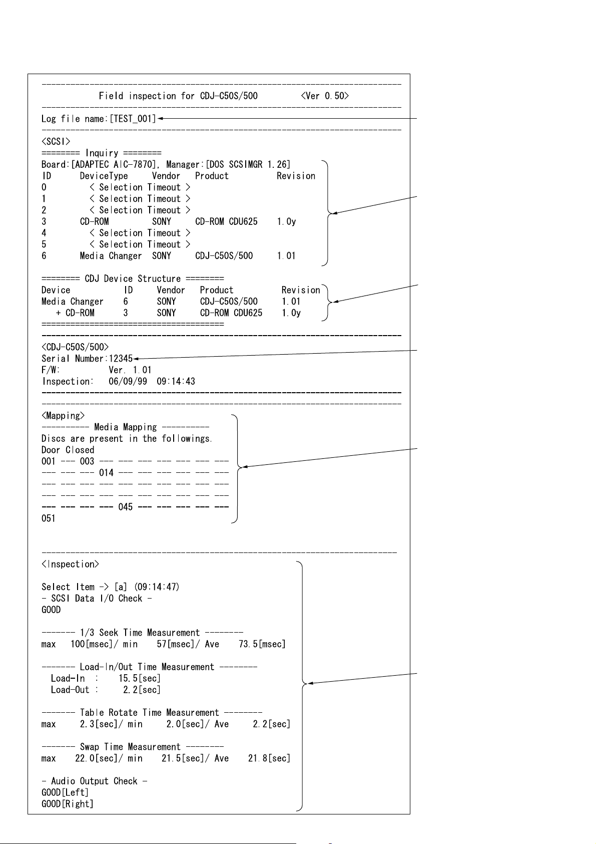
• If no problems occurred, the following will be displayed.
File name entered at step 5.
SCSI bus device
Structure of this unit detected
on the SCSI bus
Serial number entered at step 7.
Slot number (s) holding a disc.
Test results
12
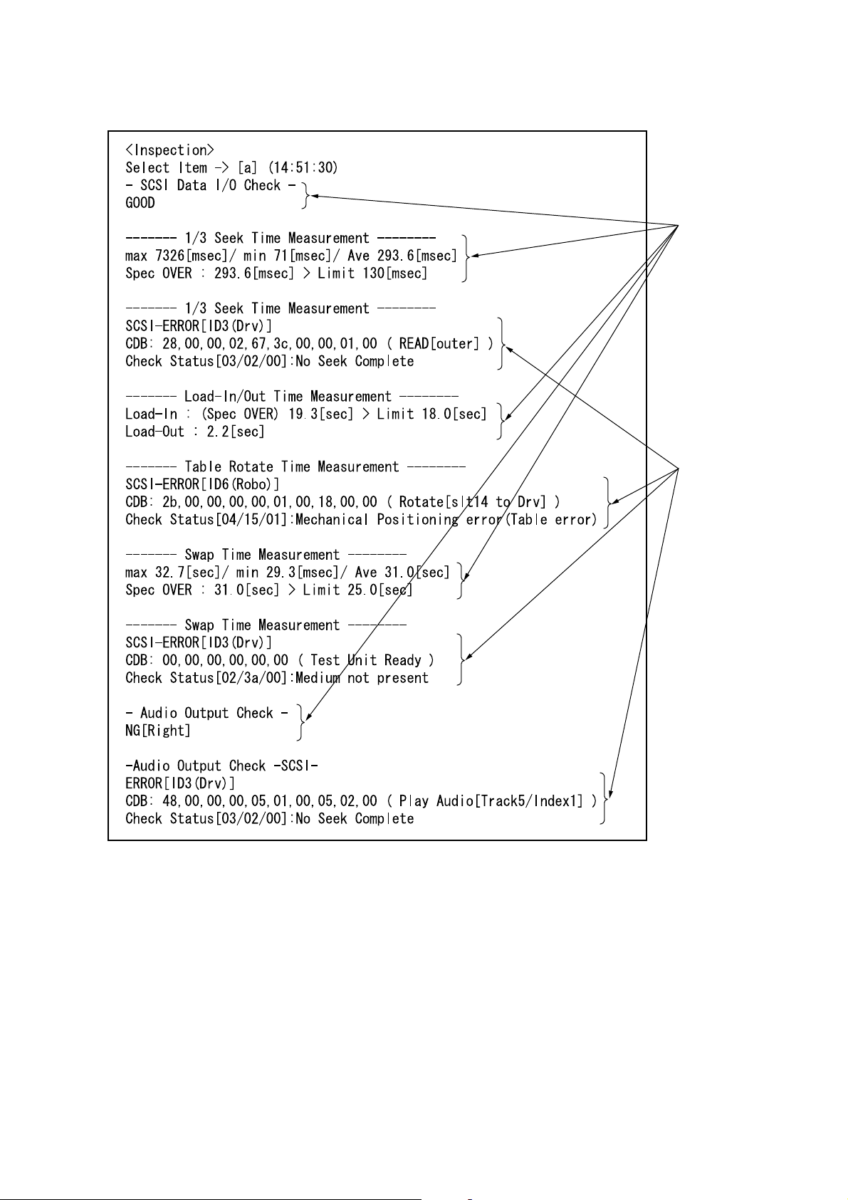
• When an error has occurred, the following is displayed
r
inspection results
Displayed when
SCSI errors occu
For details of the error codes displayed here, refer to the PDF file of
the instruction manual provided with the “FIELD50.EXE” program.
13

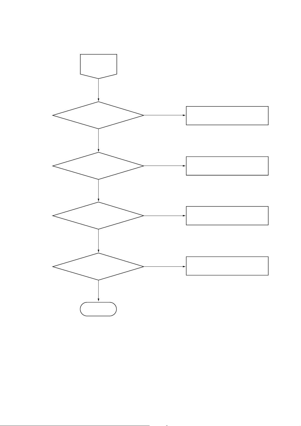
TROUBLE SHOOTING FLOW
START
POWER ON?
POWER LED lights green
EXECUTE FIELD50.EXE
DETECT as SCSI DEVICE?
CDU-625&CDJ-C50S/500 are recognized
as unique SCSI ID respectively.
CAUTION on SCREEN?
CHANGER LED FLASHING?
POWER FAILURE
SCSI FAILURE
HARDWARE ERROR
INSERT DISC?
General CD-ROM disc into SLOT 14
Green disc into SLOT 1
MEDIA MAPPING OK?
Confirm the identification between
real location and media mapping
START
INSPECTION
NO.1to6
KEY FAILURE
DISC SENSOR FAILURE
Select "A" on menu screen and start
14
START
INSPECTION
NO.1to6
NO.1 OK ?
NO.2 OK ?
NO.3 to 5 OK ?
SCSI INTEGRITY FAILURE
GO DRIVE CHECK SECTION
CHECK MECHANICAL PARTS
NO.6 OK ?
END
AUDIO FAILURE
15

CHECK POINT
POWER FAILURE
• POWER MOUNT
• FILTER MOUNT
• POWER CORD
• POWER HARNNES
SCSI FAILURE(except CDU-625)
• MAIN MOUNT
• SCSI IN/OUT MOUNT
• D.SW MOUNT
• SCSI FFC CABLE
• HARNNES(MAIN to D.SW)
HARDWARE ERROR
Check it out according to the sense code in the caution message,
There are 6 cases, as follows.
1. Mount Error (sense code 04-53-80)
• MAIN MOUNT
• MOTOR MOUNT
• PICKER
• HARNNES(MAIN to MOTOR)
2. Un mount Error(sense code 04-53-81)
Equivalent to 1
3. Disc Sensor Error
• DISC SENSOR ADJUSTMENT
• DISC SENSOR (S/R) MOUNT
• MAIN MOUNT
• HARNNES(MAIN to DISC SENSOR(S))
4. Drive Chuck Error(04-53-83)
• MAIN MOUNT
• DRIVE UNIT
• FFC (MAIN to MAC-30)
5. Drive Unchuck Error(04-53-84)
Equivalent to 4
6. Door Motor Error(04-53-85)
• D.MOTOR MOUNT
• MAIN MOUNT
• HARNNES (MAIN to D.MOTOR)
KEY FAILURE
• KEY MOUNT
• HARNNES (MAIN to KEY)
DISC SENSOR FAILURE
• DISC SENSOR ADJUSTMENT
• DISC SENSOR (S/R) MOUNT
• MAIN MOUNT
• HARNNES(MAIN to DISC SENSOR(S))
SCSI INTEGRITY FAILURE
• CSI TERMINATOR (SCSI OUT MOUNT)
• SCSI CABLE LENGTH
CHECK MECHANICAL PARTS
• MECHANICAL MAINTENANCE and ADJUSTMENT
AUDIO FAILURE
• P.JACK MOUNT
• MAC-30 MOUNT
• AUDIO HARNNES
16
DOWNLO ADING THE CHANGER PR OGRAM USING
THE UPDATEF.EXE PROGRAM
• Execute this program to rewrite the program of the changer of
this unit.
Preparations:
• IBM PC compatible Personal computer and display:
Use a personal computer with an HDD
• OS:
MS-DOS or PC-DOS version 5.0 or later.
• Floppy disk with latest UPDATEF.EXE software
(Includes the instruction manual (UPDATEF.PDF)) (CDJ-002:J2501-175-A)
• SCSI board;
The “Adaptec AVA-2904E” provided with the unit is recommended.
If this is not available, use an equivalent.
• Setting the ASPI manager;
For details, refer to “Installing the ASPI manager” on page 5.
• SCSI cable
Connection:
Connected to
SCSI connector
of the PC
SCSI
IN OUT
LINE-OUT
SCSI TERM
MODE
ID SELECT
SCSI cable (Accessory)
SCSI IN
Setting:
• DIP switch settings
1 Set SCSI TERM to “ON”, and do not
connect other SCSI equipment as much
as possible.
2 Set MODE to “ON”.
ON: Normal mode. Control the changer
using the PC.
OFF: Manual mode. Control the changer
manually using buttons.
DIGITAL-OUT
2
4
2
4
1
1
DRIVE
CHANGER
Fig. Connection of equipment
SCSI TERM
MODE
ID SELECT
2
4
DRIVE
2
4
1
1
CHANGER
3 Setting of SCSI ID of the drive Set a
desired ID number except 7.
Each SCSI ID must be set exclusively.
17
Operations:
1. Create a desired directory in the C drive of the PC, and copy the
UPDATEF.EXE file and the HEX file supplied with it there (e.g.
XXXXXX.HEX).
(The following assumes that the “CDJC50S” directory is created.)
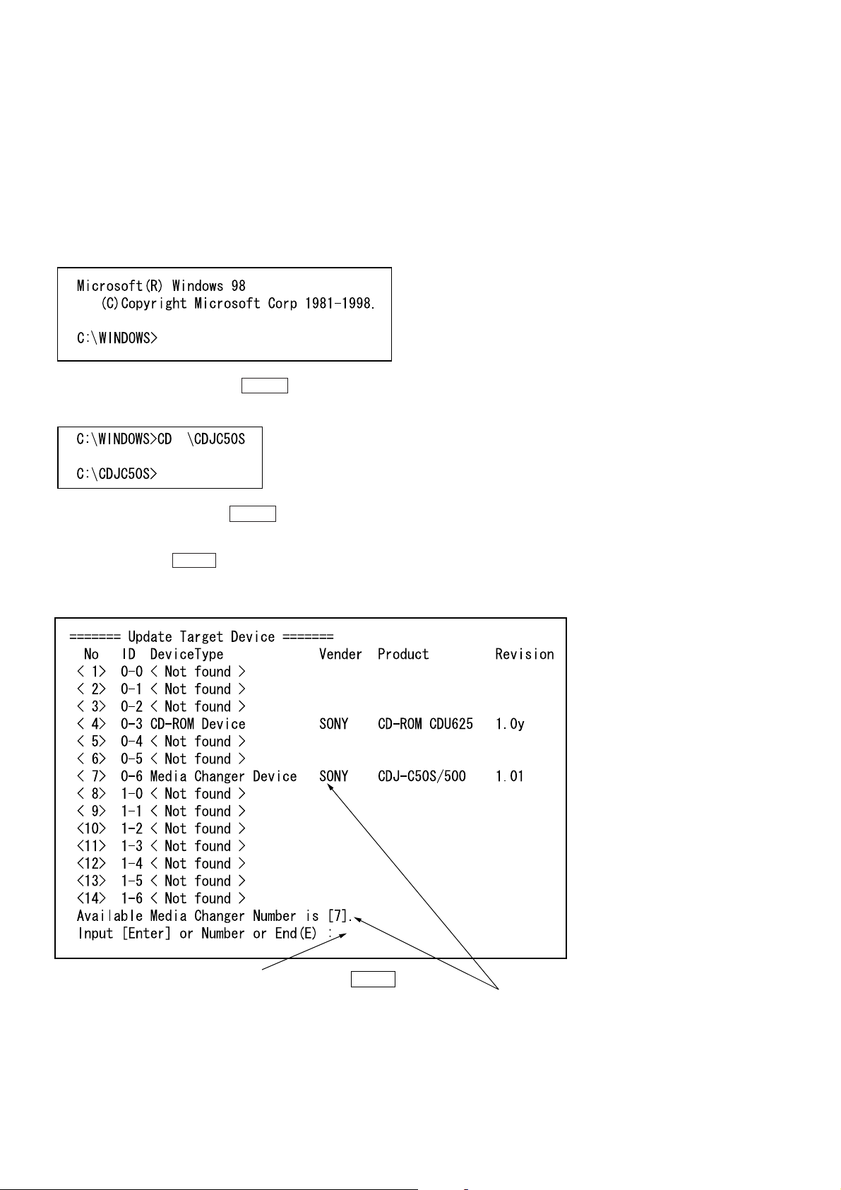
2. The download program can be executed on Windo ws 95/98 running. Close all applications first. The following describes the
state where the DOS prompt is excuted from Windows 98. The
following screen appears.
3. Enter “CD \CDJC50S” and press the ENTER key. (The following screen appears.)
4. Enter “UPDATEF” and press the ENTER key. The following
screen appears.
If CDJ-500 is detected, the number corresponded to SCSI adress
is displayed. Press the ENTER key to update program for this
changer.
(It is not necessary to enter number.)
Enter the number of the changer displayed or press the ENTER key.
18
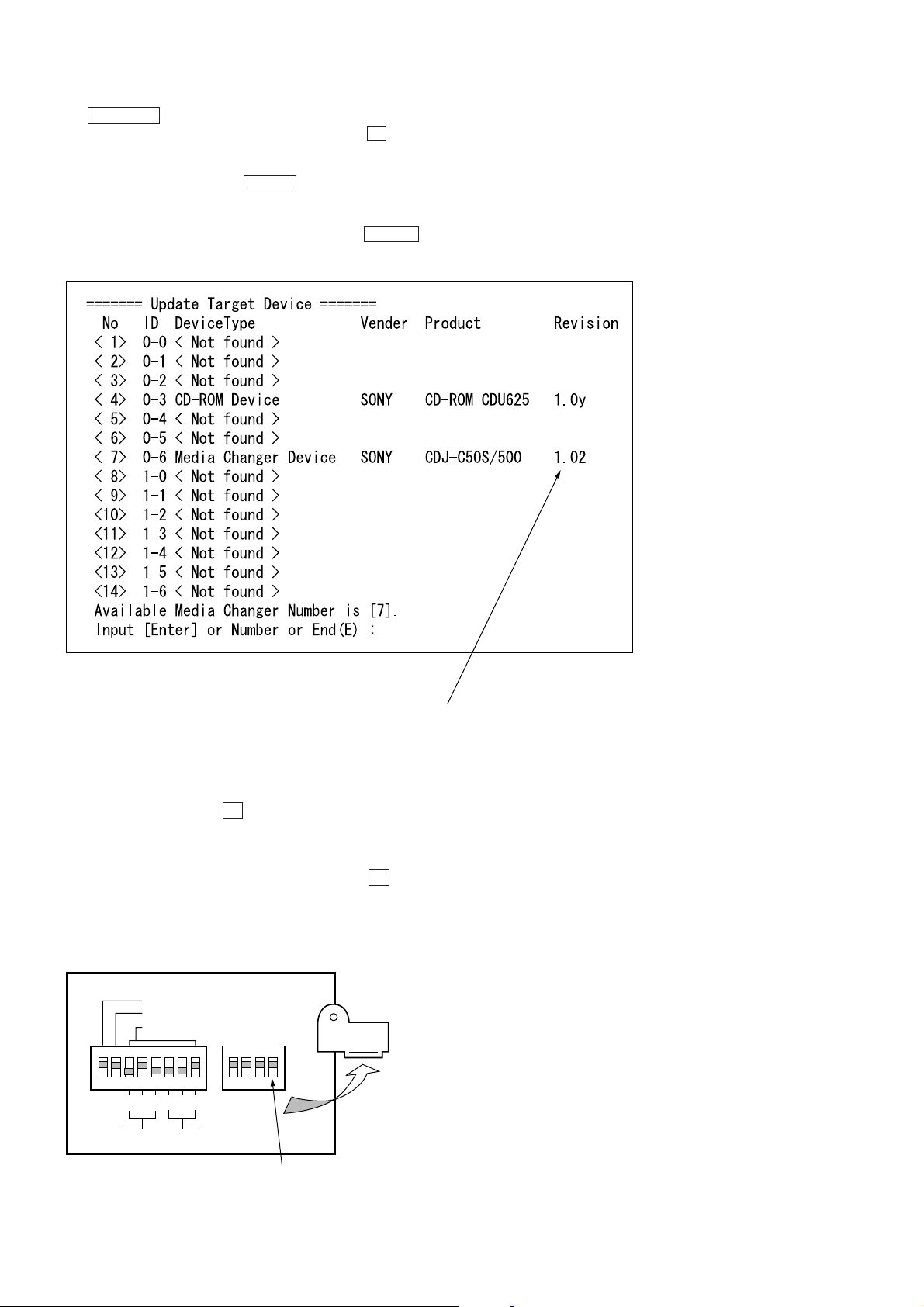
The changer detected and corresponding number are displayed.
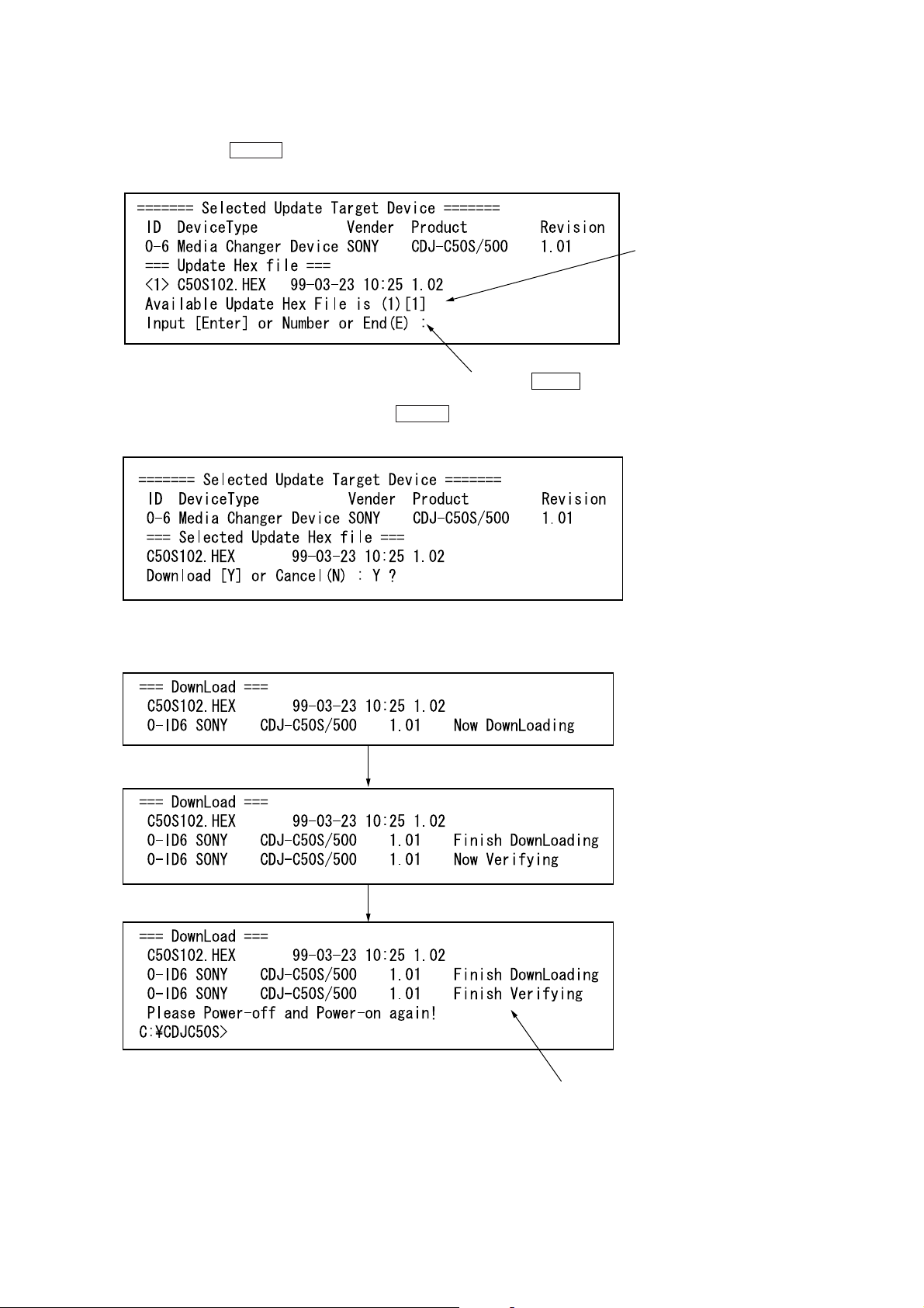
5. The program searches for the HEX file for the changer stored in
the directory and displays the lists. To download the latest HEX
file, only press the ENTER key. (It is necessary enter number,
to downlord another HEX file.)
Enter the number of the HEX file displayed or press the ENTER key.
6. As the HEX file selected is displayed, press the ENTER key.
(“Y” is entered as the default)
Detected HEX file
7. Revision 1.01 is rewritten to 1.02 and the display switches as
follows. The product information is still displayd old revision.
If downloaded successfully, “Finish Verifying” is displayed.
(If failed, “Failed Downloading” or “Failed Verifying” is displayed.)
19
8. The CHANGER indicator light up when download completes
(Fig
)
successfully. To restart the updated proglam, press the U button to turn OFF the power, and press it again to turn ON the
power again.”
9. Enter “UPDA TEF” and press the ENTER key. The following is
displayed on the screen.
10. Check the Revision here. Check that the Revision has been re-
written to that downloaded, enter “E”, and press the ENTER
key to end the program.”
Check that the Revision is the downloaded revision.
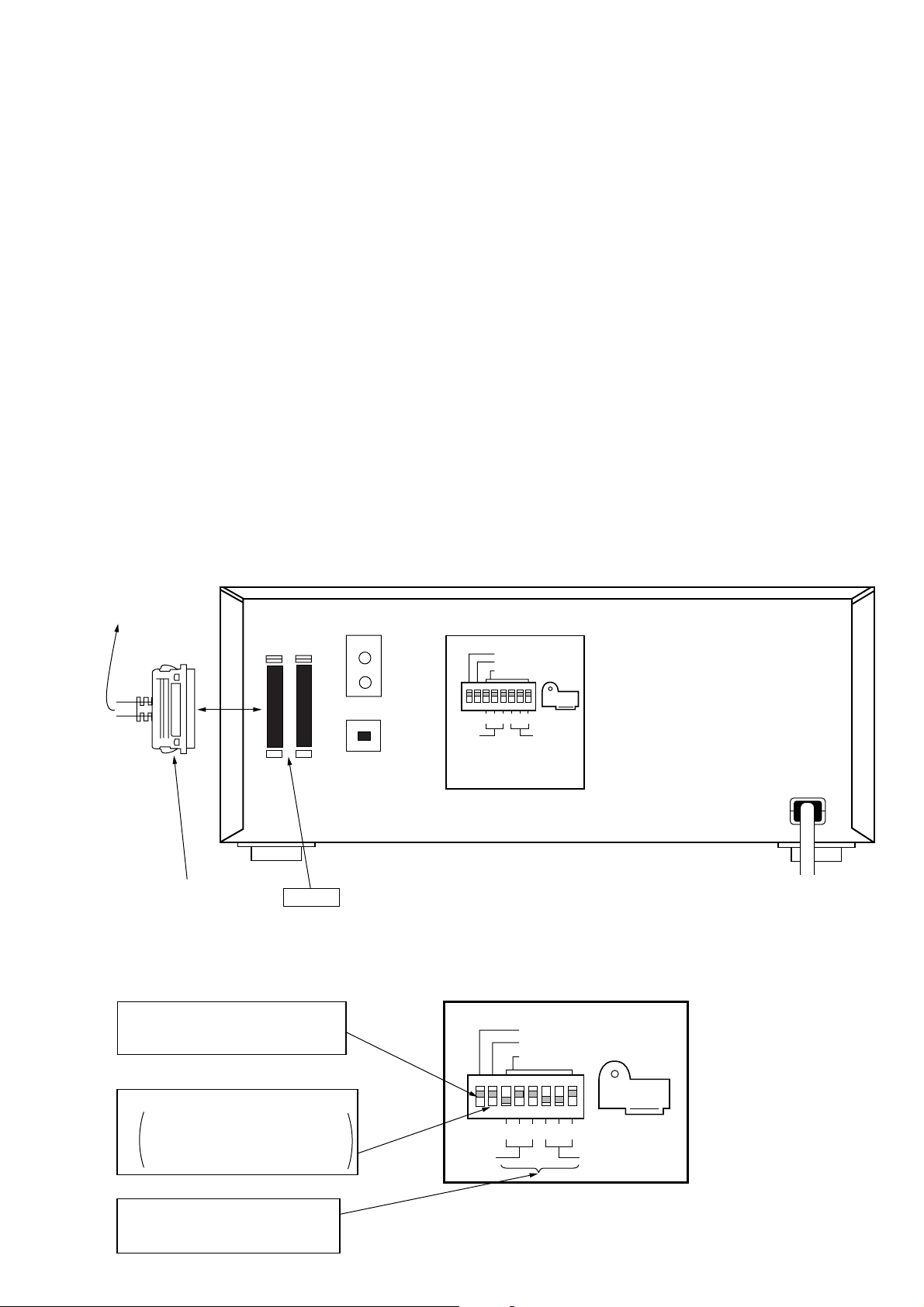
Recovering when writing failed:
• If this unit does not operate normally after writing, perform writ-
ing again using the following procedure.
1. Remove the shield with the power OFF, set the “RECOVERY”
DIP switch to OFF, press the U button and turn ON the po wer.
2. Execute the “UPDA TEF” and perform the writing process again
using the method described earlier.
3. After writing, turn OFF the power of the unit once.
4. Set the “RECOVERY” DIP switch to ON, and press the U b ut-
ton to turn ON the power.
5. Execute the “UPDATEF” using item 10 of the procedure described earlier.
Check that “Revision” has been updated.
SCSI TERM
MODE
ID SELECT
2
4
DRIVE
2
4
1
1
CHANGER
Remove the
shield.
20
RECOVERY DIP switch
ure shows the ON state
DOWNLO ADING THE DRIVE PR OGRAM USING THE
DWN-ASPI.EXE PROGRAM
• Execute this program to rewrite the program of the drive of this
unit.
Preparations:
• IBM PC compatible personal computer and display:
Use a personal computer with an HDD
• OS:
MS-DOS or PC-DOS version 5.0 or later.
Windows 95 or Windows 98 (When using Windows, follow the
settings on Windows described later.)
• Floppy disk with the “DWN-ASP1.EXE” and “625_XXX.HEX”
software
(CDM-002:J-2501-176-A)
• Floppy disk with latest drive program (625_XXX.HEX) (Supplied
as necessary)
• SCSI board:
Use “Adaptec AVA-2904E” provided with this unit.
If not available, use an equivalent.
• ASPI manager setting:
For details, refer to “Installing ASPI manager” on page 5.
• SCSI cable:
Connection:
Connected to
SCSI connector
of the PC
SCSI
IN OUT
SCSI cable (Accessory)
SCSI IN
Setting:
• DIP switch settings
1 Set SCSI TERM to “ON”, and do not
connect other SCSI equipment as much
as possible.
LINE-OUT
DIGITAL-OUT
SCSI TERM
MODE
ID SELECT
2
4
2
4
1
1
DRIVE
CHANGER
Fig. Connection of equipment
SCSI TERM
MODE
ID SELECT
2 Set MODE to “ON”.
ON: Normal mode. Control the changer
using the PC.
OFF: Manual mode. Control the changer
manually using buttons.
3 Setting of SCSI ID of the drive
Set a desired ID number except 7.
Each SCSI ID must be set exclusively.
DRIVE
2
4
2
4
1
1
CHANGER
21
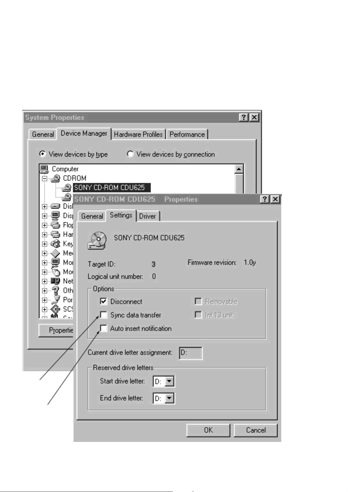
Settings on WINDOWS:
• T o run this pro gram in Windows, it must be set using the following procedure before hand.
1. Select “SYSTEM” on the “CONTROL PANEL” on Windows.
2. Display the “CD-ROM” device from “DEVICE MANAGER”,
and select “SONY CD-ROM CDU625”.
(See following diagram.)
Uncheck “Sync
data transfer”
Uncheck “Auto
insert notification”
3. Uncheck “Sync data transfer” and “Auto insert notification” at
this screen.
4. Restart and the changes made will be set.
22
Operations:
1. Create a desired directory in the C drive of the PC used, and
copy the DWN-ASPI.EXE file, and HEX file provided (e.g.
625_XXX.HEX).
(The following assumes that the “CDJC50S” directory is created.)
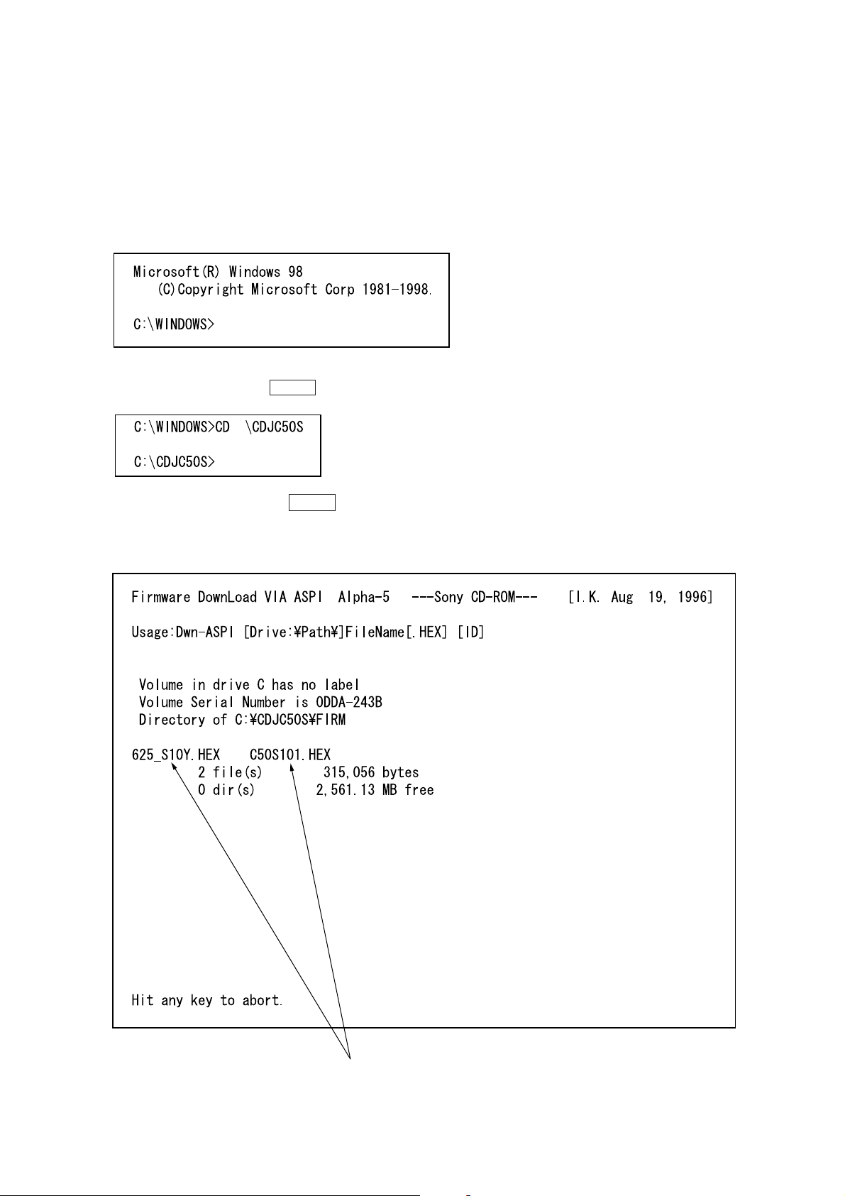
2. The downloaded program can be executed on Windows 95/98.
The following describes the state where the DOS prompt is executed from Windows 98. The following screen appears.
3. Set the directory copied with the program at item 1. Enter
“CD\CDJC50S” and press the ENTER key.
4. Enter “DWN-ASPI” and press the ENTER key. The following
screen appears.
(The following explains the example of rewriting the program
1.0W of the drive with 1.0Y.)
The HEX file in the directory executing the program is displayed.
23
5. Check that the HEX file copied in item 1 is present in the HEX
file displayed.
6. Press any key and end the program.
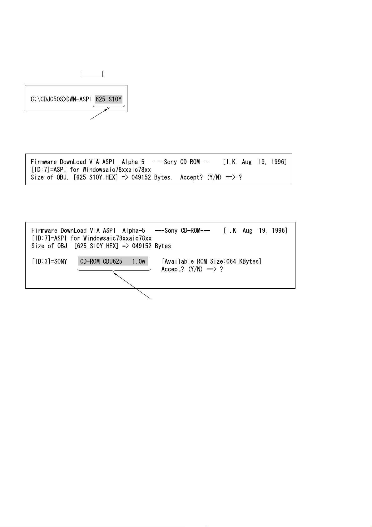
7. Enter the HEX file name checked at step 6 as “DWN-ASPI
625_XXX” and press the ENTER key.
File name copied at item 1.
8. The following screen appears. Check that the HEX file is correct and enter “Y”.
9. The following screen appears. If the ID is correct, enter “Y”.
(When “N” is entered, the CD-ROM dri ve of another ID will be
detected.)
The version of the program currently set.
24
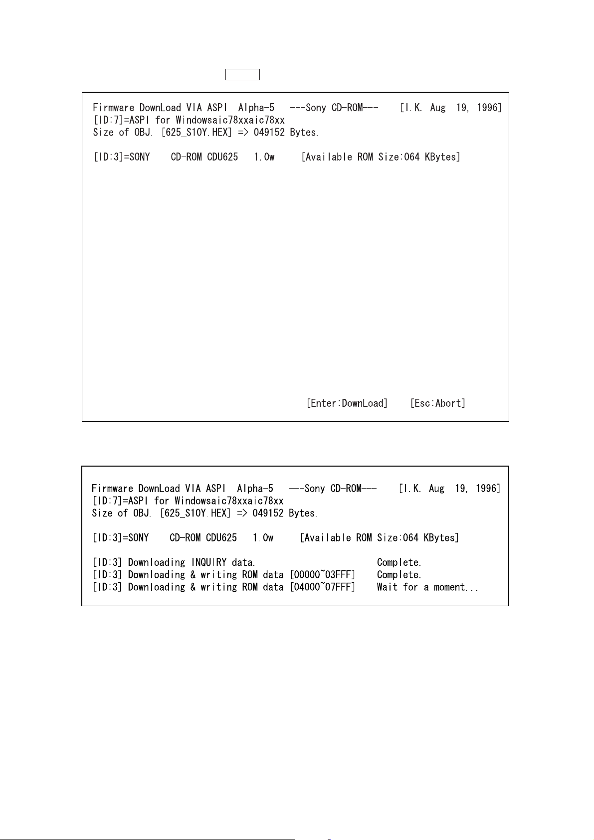
10. The following screen appears. Press the ENTER key.
11. The following screen appears and files are downloaded one by
one.
25
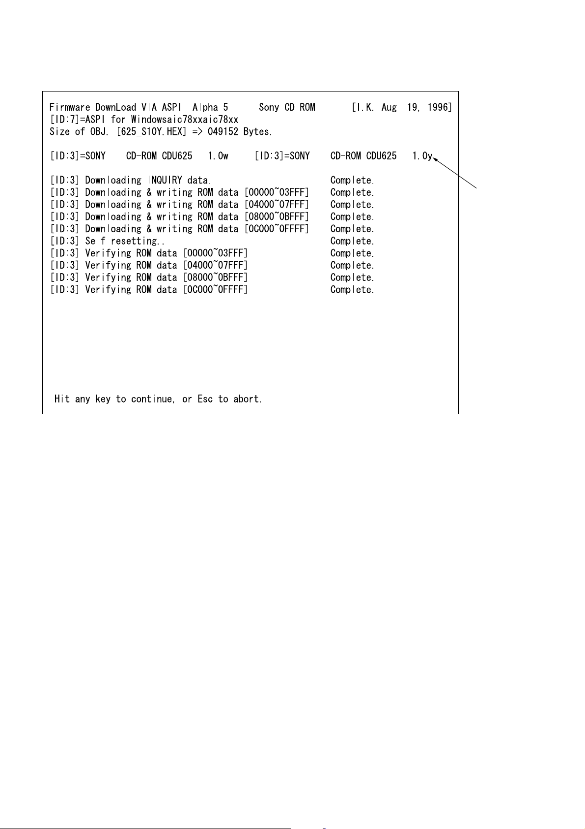
12. When downloading is finished, the following screen appears.
Newly rewritten
program version
26
13. When “Complete” is displayed at all items, it means that downloading”. If “Failure” or “Verify Error!” is displayed, correct
the cause and repeat the procedure again.
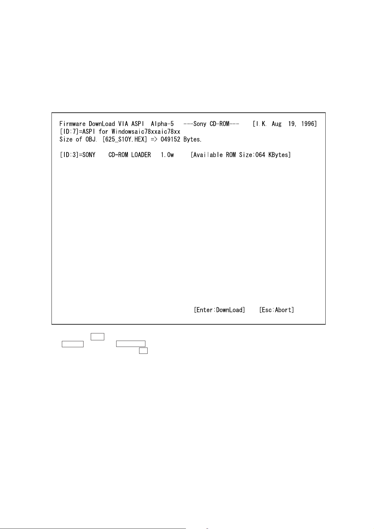
Note:
If downloading failed halfway through, the CD-R OM de vice name
changes to CD ROM LOADER. Check system environment especially SCSI configration.
To download another time, select this device.
(The screen shows the following for step 10.)
14. To end, press the ESC key.
15. The POWER indicator and CHANGER indicator of the unit
light up. To set the changes, press the U button to turn OFF
the power, and press it again to turn ON the power again.”
27
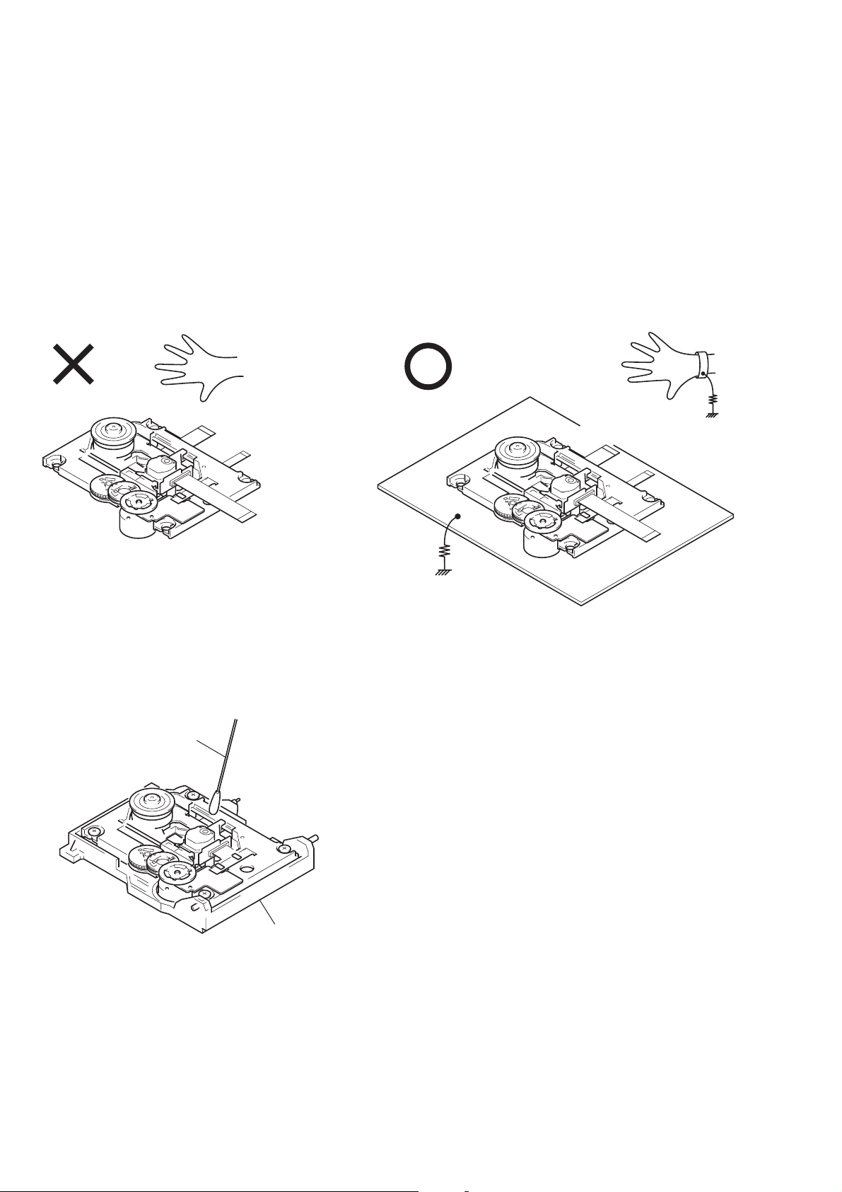
Note: Note on repairring the Base Unit assy.
y
When opening or repairing the unit, grounding is required to prevent damage caused by static electricity and is as follows:
1. Grounding for the human body
Be sure to wear a wrist-strap for grounding (with impedance
lower than 108Ω) whose other end is ground. The strap works to
drain away the static electricity build-up on the human body.
2. Grounding for the work table
Be sure to lay a conductive sheet (with impedance lower than
109Ω) on the table, such as a sheet of copper, which is ground.
3. As static electr icity built-up on clothes does not drain away, be
careful not to let your clothes touch the unit.
1
Wrist-Strap for grounding
Flexible cable
1M
Ω
Base unit assy
4. Do not apply excessive force to the lens when wiping. Optical
device is structured by very sensitiv e mechanical parts. The lens
holding mechanism may have damage if excessive force is applied.
Cotton Swab
BU holder ass
1M
Ω
2
Conductive sheet or copper plate
28
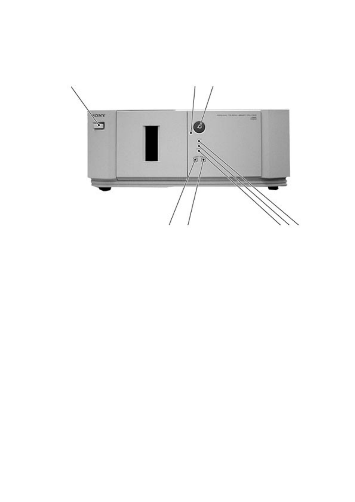
LOCATION OF PARTS AND CONTROLS
Front Panel
SECTION 2
GENERAL
1
1 u button
2 Emergency eject hole
3 OPEN button
4 POWER indicator
5 DRIVE indicator
6 CHANGER indicator
7 DISC SKIP + button
8 DISC SKIP – button
23
8
4756
29
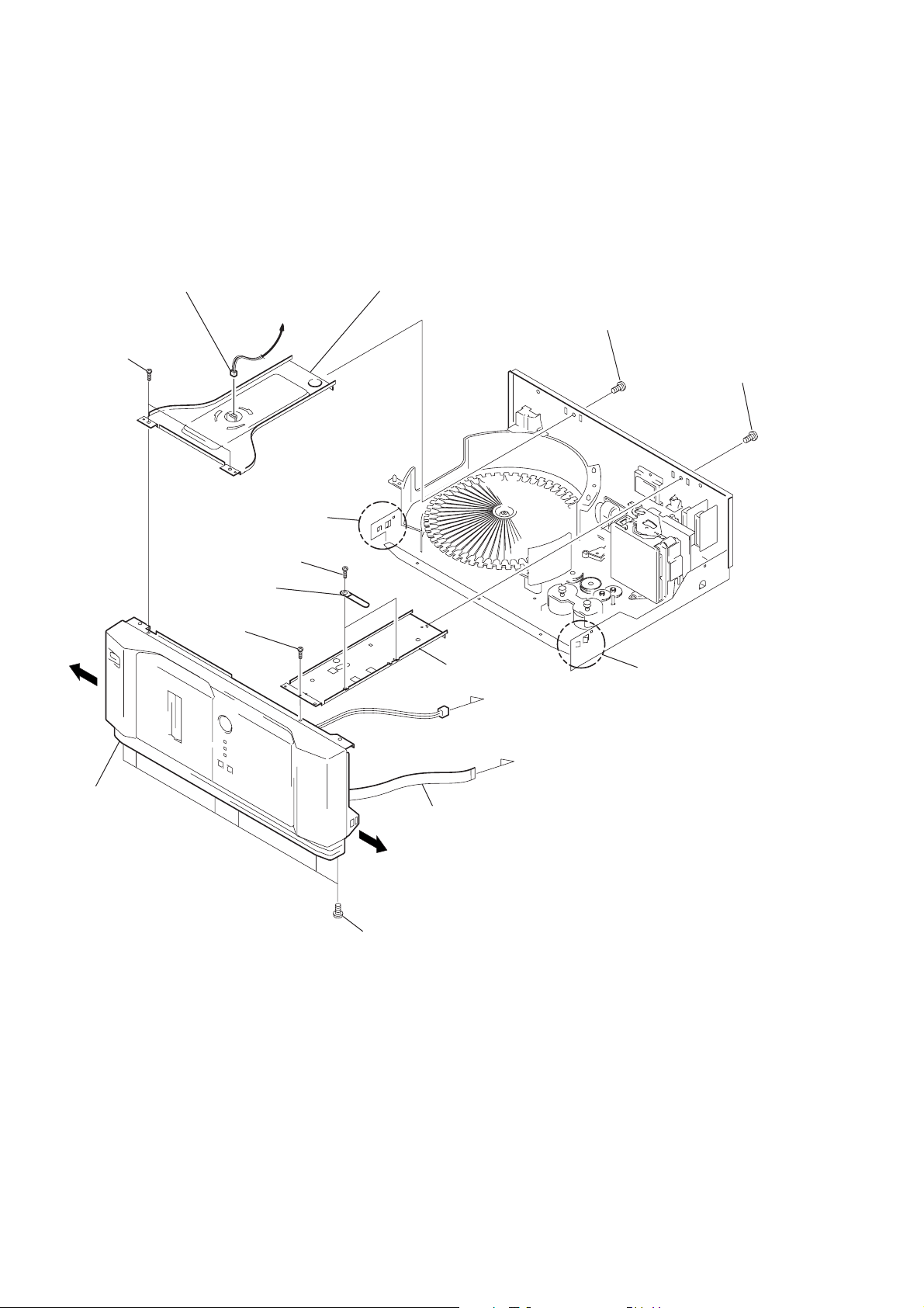
SECTION 3
)
DISASSEMBLY
Note: Follow the disassembly procedure in the numerical order given.
3-1. FRONT PANEL
3
4
Two screws (BVTT3x6)
Connector
LED board: CN841
!£
Claw
Expand the front panel
in the direction of arrow
to release catching claws.
To MAIN board
A
5
Bracket (illumination)
(with illumination assy)
1
Screw (BVTT3x6)
2
Screw (BVTT3x6)
A
Front panel
!∞
7
Screw
8
(BVTT3x6)
Two screws
6
(BVTT3x6)
Two clamps
9
0
Connector
!¡
Flat type wire
(9 core)
B
Six screws (BVTT3x10
!™
Beam
MAIN borad: CN601
MAIN borad: CN602
!¢
Claw
Expand the front panel
in the direction of arrow
to release catching claws.
B
30
 Loading...