

SONY CDJ 1000 Service Manual
COMPACT DISC PLAYER
CDJ-1000
THIS MANUAL IS APPLICABLE TO THE FOLLOWING MODEL(S) AND TYPE(S).
ORDER NO.
RRV2468
Type
KUC O AC120V
TL O AC110- 240V
WY O AC220- 240V
Model
Power Requirement
CDJ-1000
CONTENTS
1. SAFETY INFORMATION
2. EXPLODED VIEWS AND PARTS LIST
3. BLOCK DIAGRAM AND SCHEMATIC DIAGRAM 12
4. PCB CONNECTION DIAGRAM
5. PCB PARTS LIST
6. ADJUSTMENT
7. GENERAL INFORMATION
................................................
.....................................................
.......................................
.................
...........................
..................................
38
52
57
59
Remarks
2
4
7.1 DIAGNOSIS
7.1.1 SERVICE MODE
7.1.2 ERROR DISPLAY
7.1.3 DISASSEMBLY
7.1.4 PART REPLACEMENT METHOD OF JOG
SECTION
7.1.5 ABOUT ELECTRIC DISCHARGE
7.1.6 SEQUENCE AFTER THE POWER ON.70
7.2 PARTS
7.2.1 IC
8. PANEL FACILITIES AND SPECIFICATIONS
...................................................
..................................
.................................
.....................................
...............................................
..........
..........................................................
...........................................................
.......
59
59
61
62
66
69
71
71
87
PIONEER ELECTRONIC CORPORATION 4-1, Meguro 1-chome, Meguro-ku, Tokyo 153-8654, Japan
PIONEER ELECTRONICS SERVICE, INC. P.O. Box 1760, Long Beach, CA 90801-1760, U.S.A.
PIONEER ELECTRONIC NV Haven 1087, Keetberglaan 1, 9120 Melsele, Belgium
PIONEER ELECTRONICS ASIACENTRE PTE. LTD. 253 Alexandra Road, #04-01, Singapore 159936
c
PIONEER ELECTRONIC CORPORATION 2001
T – ZZY JULY 2001 Printed in Japan
CDJ-1000
1. SAFETY INFORMATION
This service manual is intended for qualified service technicians; it is not meant for the casual
do-it-yourselfer. Qualified technicians have the necessary test equipment and tools, and have been
trained to properly and safely repair complex products such as those covered by this manual.
Improperly performed repairs can adversely affect the safety and reliability of the product and may
void the warranty. If you are not qualified to perform the repair of this product properly and safely, you
should not risk trying to do so and refer the repair to a qualified service technician.
WARNING
This product contains lead in solder and certain electrical parts contain chemicals which are known to the state of California to
cause cancer, birth defects or other reproductive harm.
Health & Safety Code Section 25249.6 – Proposition 65
NOTICE
(FOR CANADIAN MODEL ONLY)
Fuse symbols (fast operating fuse) and/or (slow operating fuse) on PCB indicate that replacement parts
must be of identical designation.
REMARQUE
(POUR MODÈLE CANADIEN SEULEMENT)
Les symboles de fusible (fusible de type rapide) et/ou (fusible de type lent) sur CCI indiquent que les
pièces de remplacement doivent avoir la même désignation.
(FOR USA MODEL ONLY)
1. SAFETY PRECAUTIONS
The following check should be performed for the
continued protection of the customer and service
technician.
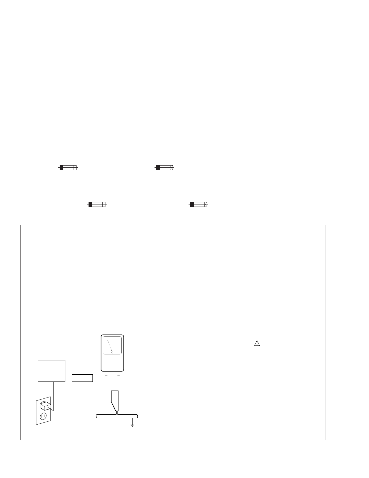
LEAKAGE CURRENT CHECK
Measure leakage current to a known earth ground
(water pipe, conduit, etc.) by connecting a leakage
current tester such as Simpson Model 229-2 or
equivalent between the earth ground and all exposed
metal parts of the appliance (input/output terminals,
screwheads, metal overlays, control shaft, etc.). Plug
the AC line cord of the appliance directly into a 120V
AC 60 Hz outlet and turn the AC power switch on. Any
current measured must not exceed 0.5 mA.
Reading should
not be above
0.5 mA
Earth ground
Device
under
test
Also test with plug
reversed
(Using AC adapter
plug as required)
Leakage
current
tester
Test all exposed
metal surfaces
AC Leakage Test
ANY MEASUREMENTS NOT WITHIN THE LIMITS
OUTLINED ABOVE ARE INDICATIVE OF A POTENTIAL SHOCK HAZARD AND MUST BE CORRECTED BEFORE RETURNING THE APPLIANCE
TO THE CUSTOMER.
2. PRODUCT SAFETY NOTICE
Many electrical and mechanical parts in the appliance have special safety related characteristics. These
are often not evident from visual inspection nor the
protection afforded by them necessarily can be obtained by using replacement components rated for
voltage, wattage , etc. Replacement parts which have
these special safety characteristics are identified in
this Service Manual.
Electrical components having such features are
identified by marking with a
on the parts list in this Service Manual.
The use of a substitute replacement component which
does not have the same safety characteristics as the
PIONEER recommended replacement one, shown in
the parts list in this Service Manual, may create shock,
fire, or other hazards.
Product Safety is continuously under review and
new instructions are issued from time to time. For
the latest information, always consult the current
PIONEER Service Manual. A subscription to, or additional copies of, PIONEER Service Manual may be
obtained at a nominal charge from PIONEER.
on the schematics and
2
CDJ-1000
THIS PIONEER APPARATUS CONTAINS
LASER OF CLASS 1.
SERVICING OPERATION OF THE APPARATUS
SHOULD BE DONE BY A SPECIALLY
INSTRUCTED PERSON.
The AEL(accessible emission level) of the laser power output is less then CLASS 1
but the laser component is capable of emitting radiation exceeding the limit for
CLASS 1.
A specially instructed person should servicing operation of the apparatus.
IMPORTANT
LASER DIODE CHARACTERISTICS
MAXIMUM OUTPUT POWER: 5 mW
WAVELENGTH: 780 – 785 nm
WARNING !
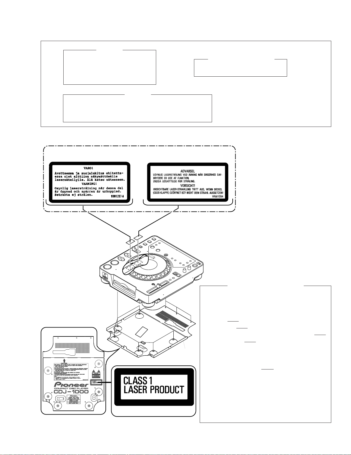
LABEL CHECK (for CDJ-1000/ TL and WY types)
CDJ-1000/ TL and WY Types Only
Bottom Plate
Printed on the Bottom Plate
Additional Laser Caution
1. Laser Interlock Mechanism
The position of the switch (S1) for detecting loading
completion is detected by the system microprocessor, and
the design prevents laser diode oscillation when the switch
is not in LPS1 terminal side (when the mechanism is not
clamped and LPS1 signal is high level.) Thus, the interlock
will no longer function if the switch is deliberately set to LPS1
terminal side. ( if LPS1 signal is low level ).
In the test mode∗ the interlock mechanism will not function.
Laser diode oscillation will continue, if pin 33 of CXA1782CQ
(IC101) on the MOTHER BOARD ASSY is connected to
GND, or pin 43 of IC701 (LDON) is connected to low level
(ON), or else the terminals of Q101 are shorted to each
other (fault condition).
2. When the cover is opened, close viewing of the objective
lens with the naked eye will cause exposure to a Class 1
laser beam.
∗ : Refer to page 57.
3
CDJ-1000
2. EXPLODED VIEWS AND PARTS LIST
NOTES:• Parts marked by "NSP" are generally unavailable because they are not in our Master Spare Parts List.
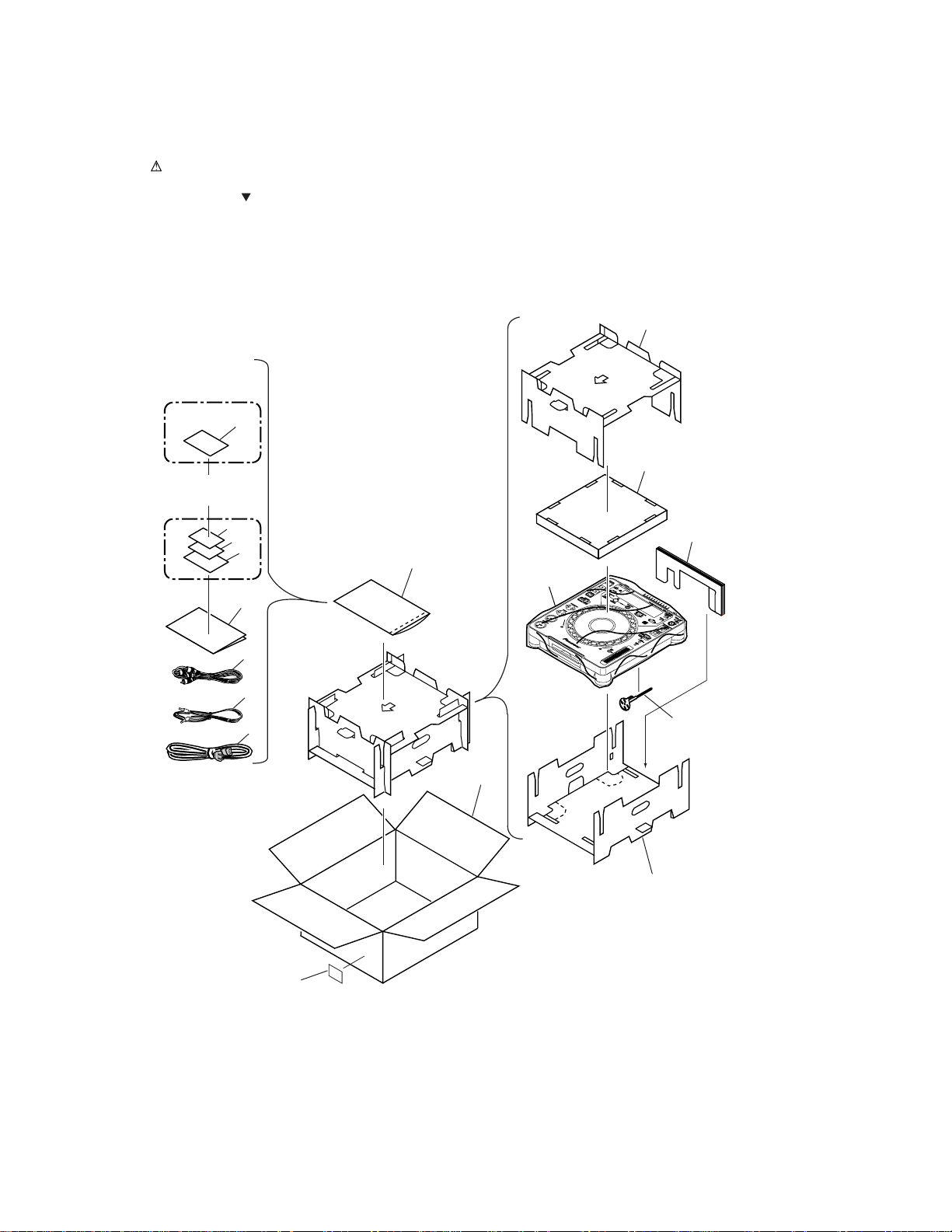
2.1 PACKING
The mark found on some component parts indicates the importance of the safety factor of the part.
•
Therefore, when replacing, be sure to use parts of identical designation.
Screws adjacent to mark on the product are used for disassembly.
•
9
KUC Type
Only
2
10
WY Type
Only
16
17
14
11
7
13
4
6
5
1
12
3
8
15
4
(1) PACKING PARTS LIST
Mark No. Description Part No.
1 Power Cord See Contrast table (2)
NSP 2 Warranty Card See Contrast table (2)
3 Forced Eject Pin DEX1013
4 Operating Instructions See Contrast table (2)
5 Control Cord (L= 1m) PDE1247
CDJ-1000
NSP 7 Polyethylene Bag Z21-038
NSP 14 Mini Catalogue See Contrast table (2)
NSP 15 Label See Contrast table (2)
NSP 16 Pamphlet See Contrast table (2)
NSP 17 MMC Catalog See Contrast table (2)
6 Audio Cable (L = 1.5m) VDE1033
(0.03 × 230 × 340)
8 Pad (A) DHA1518
9 Pad (B) DHA1519
10 Pad (C) DHA1523
11 Pad (D) DHA1524
12 Packing Case See Contrast table (2)
13 Sheet RHX1006
(2) CONTRAST TABLE
CDJ-1000/KUC, TL and WY types are constructed the same except for the following :
Mark No. Symbol and Description
1
NSP
Power Cord
2
Warranty Card
4
Operating Instructions (English)
4
Operating Instructions (English/ Spanish)
4
Operating Instructions (English/ French
/German/ Italian/ Dutch/ Spanish)
KUC Type TL Type WY Type
ADG7021
ARY7043
DRB1297
Not used
Not used
Part No.
ADG1154
Not used
Not used
DRB1299
Not used
Remarks
ADG1154
Not used
Not used
Not used
DRB1298
NSP
NSP
NSP
NSP
12
Packing Case
14
Mini Catalogue
15
Label
16
Pamphlet
17
MMC Catalog
DHG2145
Not used
VRW1629
Not used
Not used
DHG2146
Not used
Not used
Not used
Not used
DHG2129
DRY1194
Not used
DRY1188
DRY1195
5
CDJ-1000
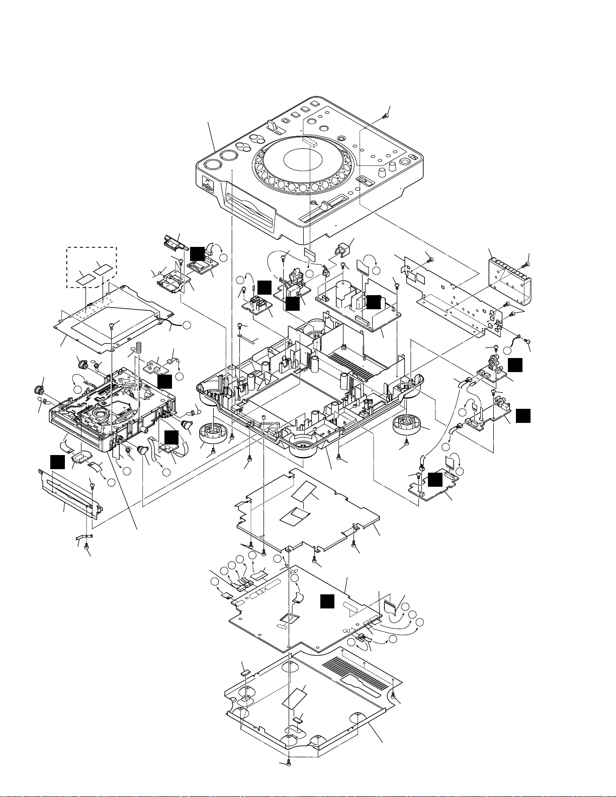
2.2 EXTERIOR (1/2) SECTION
25
TL and WY Type
Only
44
33
B
P
48
47
29
49
47
M
48
28
C
11
47
47
H
47
47
17
E
37
B
D
G
8
47
I
9
Refer to
"2.3 EXTERIOR (2/2) SECTION".
40
10
Q
47
I
6
45
46
47
33
3
25
26
K
13
18
25
47
G
L
47
39
5
E
14
33
15
F
C
23
F
A
H
2
38
M
J
25
33
4
37
47
47
47
47
47
D
32
30
47
47
27
31
34
48
Refer to
"2.4 SLOT-IN MECHANISM
SECTION".
24
L
36
47
I
12
19
H
47
G
1
K
J
A
A
41
43
41
48
35
47
21
22
C
D
E
20
F
B
16
48
42
7
6

CDJ-1000
(1) EXTERIOR (1/2) SECTION PARTS LIST
Mark No. Description Part No. Mark No. Description Part No.
1 MAIN Assy DWX2161
2 MMCB Assy DWX2169
3 SPCN Assy DWX2170
4 STCN Assy DWX2171
5 SLMB Assy DWX1309
6 PSWB Assy See Contrast table (2)
7 DABB Assy DWX2162
8 JACB Assy DWX2163
9 DOUT Assy DWX2164
10 FLRB Assy DWX2166
11 SW POWER SUPPLY Assy DWR1344
12 25P Flexible Cable/60V DDD1189
13 12P Flexible Cable/60V DDD1190
14 4P Flexible Cable/60V DDD1191
15 Earth Lead Unit/300V DDF1015
16 Connector Assy 3P DKP3546
17 Connector Assy 3P DKP3548
18 FPC D5 Slot DNP1951
19 Jumper Wire 03P D20PYY0310E
20 Jumper Wire 05P D20PYY0510E
21 Jumper Wire 09P D20PYY0910E
22 Jumper Wire 15P D20PYY1510E
23 Connector Assy PF03PP-B30
24 Connector Assy PG07KK-F15
25 Float Spring (G5) DBH1485
26 Earth Spring DBH1398
27 Chassis DNK3869
NSP 28 Rear Panel See Contrast table (2)
29 Heat Sink DNG1081
30 Power Knob DAC1895
31 Front Plate DNH2480
32 Cord Clamper RNH-184
33 Damper CNV6011
34 Earth Plate (CU) VBK1070
35 Shield Case DNH2481
36 Shield Cushion DEC2445
37 Insulator Assy DXA1904
38 Memory Holder DNK3884
39 Flap Spring DBH1487
40 SD Flap DNK3883
NSP 41 Silicone Rubber D5L DEB1456
42 Bottom Plate DNH2479
43 Bottom Cushion DEC2444
44 Mecha Plate DNH2339
45 Caution Label See Contrast table (2)
NSP 46 Caution Label HE See Contrast table (2)
47 Screw BPZ30P080FZK
48 Screw BBZ30P060FZK
49 Screw BBZ30P120FZK
(2) CONTRAST TABLE
CDJ-1000/KUC, TL and WY types are constructed the same except for the following :
Mark No. Symbol and Description
6
NSP
NSP
PSWB Assy
28
Rear Panel
45
Caution Label
46
Caution Label HE
KUC Type TL Type WY Type
DWS1312
DNC1576
Not used
Not used
Part No.
DWS1311
DNC1577
VRW1094
VRW1297
Remarks
DWS1311
DNC1567
VRW1094
VRW1297
7
CDJ-1000
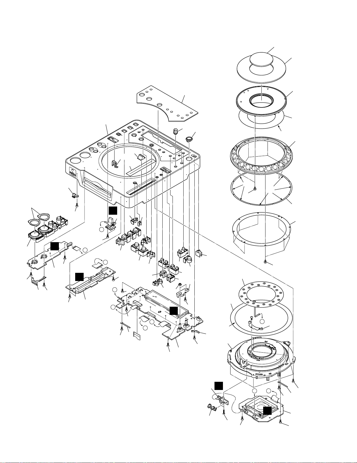
2.3 EXTERIOR (2/2) SECTION
20
25 (2/2)
41
22
23
K
30
4
26
45
E
45
C
45
39
45
24
45
40
45
L
45
E
45
C
45
2
D
M
45
3
43
31
29
27
28
25 (1/2)
B
17
16
*
8
7 (1/3)
1
7 (3/3)
9
× 8
11
32
19
36
33
42
44
34
45
35
18
21
37
7 (2/3)
14
*
10
1
1
*
10
J
D
1
*
38
12
45
1
45
A
13
6
Lubricant : ZLB-HFD1600 (GEM1038)
1
*
15
O
46
A B
N
45
45
45
39
5
45
8

EXTERIOR (2/2) SECTION PARTS LIST
•
Mark No. Description Part No.
1 MFLB Assy DWG1548
2 KSWB Assy DWS1307
3 SLDB Assy DWS1308
4 RSWB Assy DWS1310
5 JFLB Assy DWG1549
6 JOGB Assy DWG1550
7 JOG Sheet Assy DXB1757
8 JOG Dial A DNK3870
9 JOG Dial B DNK3871
10 Screw PBA1062
11 Encoder Plate DEC2425
12 JOG Holder DNK3872
13 JOG Stay Assy DXB1760
14 Sheet SW DSX1057
15 Encoder Guide DNK3873
16 JOG Plate DAH2052
17 JOG Panel DAH2051
18 VR Stay DNF1663
19 Flange Nut (M9) DBN1004
20 Control Panel DNK3875
CDJ-1000
21 Eject Guard DNK3958
22 Card Lens DNK3885
23 Ring Lens DNK3880
24 Set Knob (PLAY) Assy DXB1750
25 Mode Lens DNK3881
26 Set Knob (HS) DAC1986
27 Set Knob (LOOP) DAC1995
28 Re-loop Knob DAC1992
29 Set Knob (TIME) DAC1991
30 Tempo Reset Knob DAC1993
31 Tempo Lens DNK3882
32 Set Knob (MT) DAC1987
33 Mode Select Knob DAC1989
34 Set Knob (SC) DAC1988
35 Eject Knob DAC1990
36 Set Knob (MEMO) DAC1994
37 Slide SW Knob DAC1926
NSP 39 Cord Clamper Z09-061
38 Earth Plate (CU) VBK1070
40 Card Plate DBK1212
41 Slide Sheet 1C DAH1988
42 Display Panel DAH2022
43 Slide Knob DNK2936
44 Rotary Knob C DAA1143
45 Screw BPZ30P080FZK
46 Screw BPZ20P120FMC
9
CDJ-1000
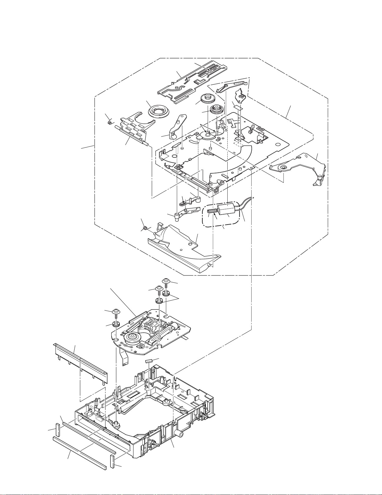
2.4 SLOT-IN MECHANISM SECTION
3
*
7
3
18
Refer to
"2.5 TRAVERSE MECHANISM ASSY-S".
19
26
10
17
15
14
3
*
6
9
2.
*
4
26
8
13
16
26
25
5
1
3
*
29
2
11
12
10
21
22
23
27
25
21
28
20
Dyefree : ME-913A (ZLX-ME413A)
2.
*
Grease : ZLB-PN397B
3.
*
CDJ-1000
SLOT-IN MECHANISM SECTION PARTS LIST
•
Mark No. Description Part No. Mark No. Description Part No.
NSP 1 DC Motor DXM1093
2 Connector Assy PF02PY-B32
3 Clamp Spring DBH1374
4 Guide Spring DBH1375
5 SW Lever Spacer (PET) DEC2420
6 Loading Lever DNK3406
7 Main Cam DNK3407
8 Lever B DNK3558
9 Lever A DNK3564
10 Clamp Arm DNK3576
11 Loading Base Assy-S DEA1022
12 Eject Lever DNK3684
NSP 13 Worm Gear DNK3910
14 Loading Gear DNK3911
15 Drive Gear DNK3912
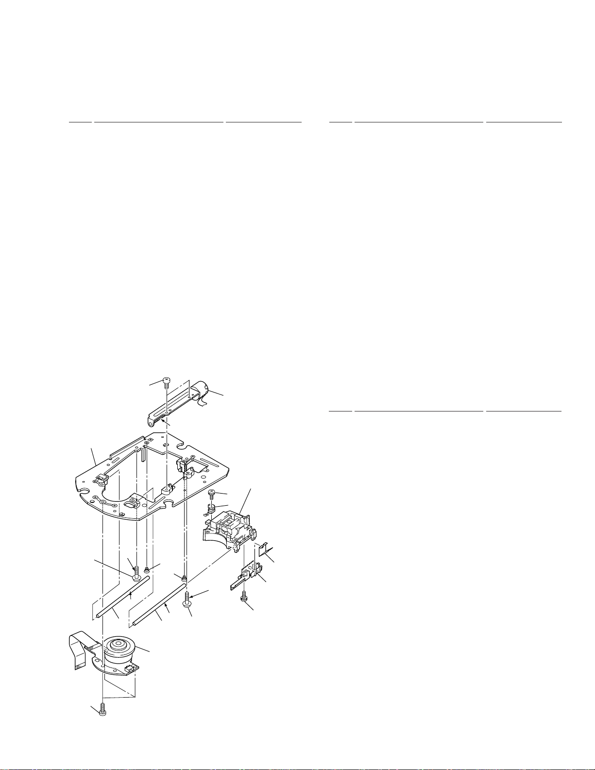
2.5 TRAVERSE MECHANISM ASSY-S
12
2
16 Disc Guide DNK3914
NSP 18 Slot-in Mechanism G5 Assy DXA1906
•
17 Clamper D4 Assy DXA1881
19 Traverse Mechanism Assy-S DXX2502
20 Float Base (G5) Assy DXB1748
21 Vessel Cushion C DEC2424
22 Vessel Cushion A DEC2257
23 Vessel Cushion B DEC2258
24 • • • • •
25 Float Rubber D3 DEB1404
26 Float Fastener DBA1139
27 Front Sheet DED1132
28 Spacer POR (T3) DEB1467
29 Loading Motor Assy-S DEA1008
TRAVERSE MECHANISM ASSY-S
PARTS LIST
Mark No. Description Part No.
13
10
5
*
3
5
9
4
4
*
5
*
8
6
6
4
*
6
*
4
8
1
Screw Lock #300UB: ZBA-300UB
4.
*
Grease: ZLB-PN397B
5.
*
Grease: ZLB-PN948P
6.
*
7
11
5
NSP 1 Spindle Motor DXM1138
NSP 2 Stepping Motor DXM1142
NSP 3 Pickup Assy VWY1069
NSP 4 Adjust Screw DBA1119
NSP 5 Precision Screw DBA1124
NSP 6 Skew Spring DBH1437
NSP 7 Joint Spring DBK1188
NSP 8 Guide Shaft DLA1840
NSP 9 Slider G4 DNK3733
NSP 10 Mechanism Frame G5 DNK3776
NSP 11 Joint DNK3777
12 Screw BPZ20P080FMC
13 Screw BPZ26P080FMC
11
1
23
CDJ-1000
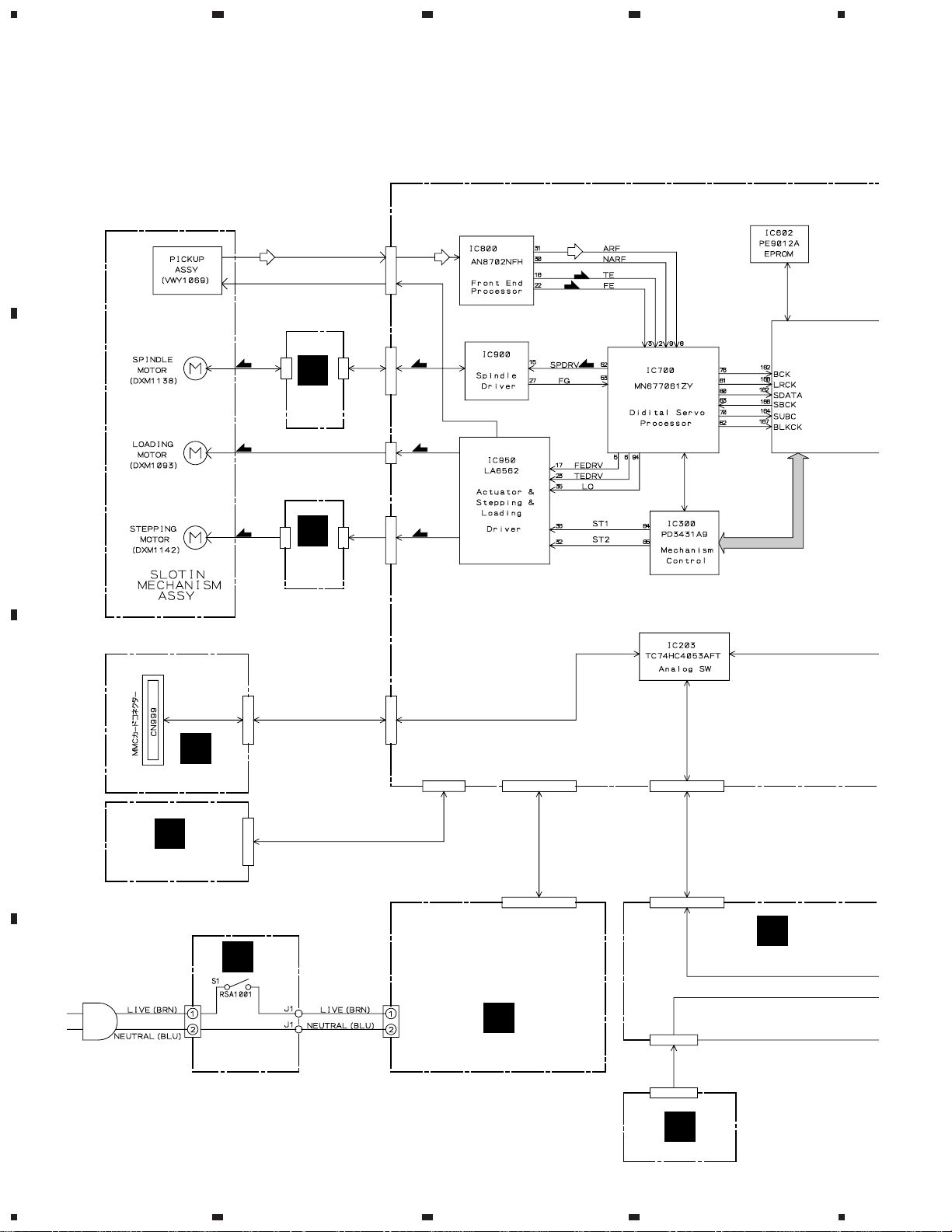
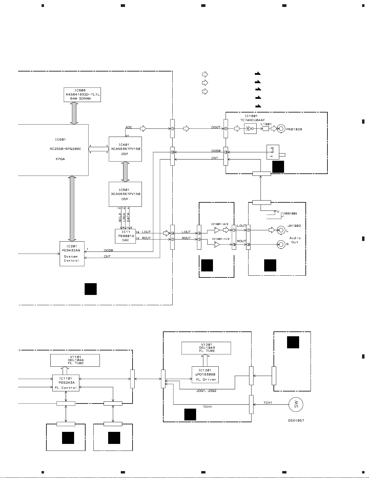
3. BLOCK DIAGRAM AND SCHEMATIC DIAGRAM
3.1 BLOCK DIAGRAM
A
4
(RF)
CN911
(SM)
B
CN912
CN800
(RF)
CN900
(RF)
(FS)
(TS)
(SM)(SM)
SPCN
ASSY
CN302
B
(LM)
(CM)
CN914CN913
C
(LM)
CN950
(CM)
STCN
ASSY
CN202CN99
C
MMCB ASSY
F
CN1501
CN102
CN101
CN203
D
FLRB ASSY
CN2217 CN1101
J
Q
AN1
D
PSWB ASSY
CN1
P
SW POWER SUPPLY ASSY
J1701
J1701
MFLB ASSY
K
RSWB ASSY
12
1234
5
678
CDJ-1000
CN12
CN13
(PB)
CN11
SIGNAL ROUTE
(D)
: DIGITAL SIGNAL
(PB)
: PB SIGNAL
(RF)
: RF SIGNAL
CN1801
CN1802
(PB)
(D)(D)(D)
(FS)
: FOCUS SERVO LOOP LINE
(TS)
: TRACKING SERVO LOOP LINE
(SM)
: SPINDLE MOTOR ROUTE
(CM)
: CARRIAGE MOTOR ROUTE
(LM)
: LOADING MOTOR ROUTE
JA1801
Digital Out
(D)
S1801
Digital Out
ON/OFF
DOUT ASSY
(PB)
I
CN1904
JA1901
Control Jack
BKB1017
J1801
A
B
MAIN ASSY
A
J1101 J1103
CN1102
J1202
CN1901 CN1902
G
JFLB ASSY
N
DABB
ASSY
CN1903
H
J1601 J1601
CN1201
JACB
ASSY
O
JOGB ASSY
Sheet SW
C
D
CN1401 CN1301
L
SLDB ASSYMKSWB ASSY
5
13
6
7
8
1
CDJ-1000
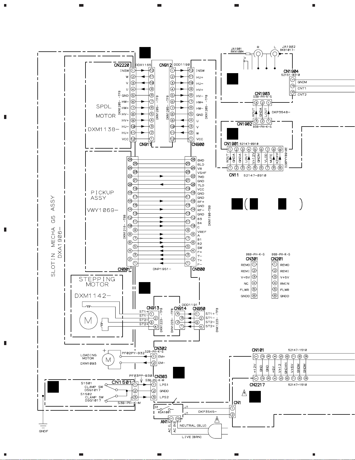
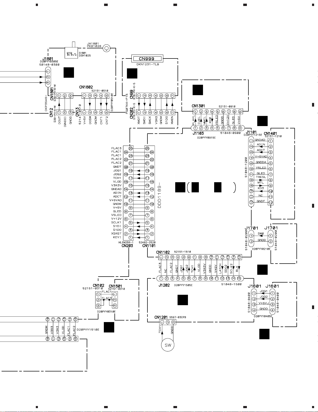
3.2 OVERALL WIRING DIAGRAM
A
B
23
CONTROL
AUDIO OUT
SPCN ASSY
B
(DWX2170)
JACB ASSY
H
(DWX2163)
DABB ASSY
G
(DWX2162)
4
(WHT)
(WHT)
A
A 1/4 - A 4/4
MAIN ASSY
TRAVERSE MECHANISM ASSY-S
DXX2502
C
STCN ASSY
C
(DWX2171)
(DWX2161)
CONNECTOR FOR I/F
(FOR IC201)(FOR IC300)
Q
PSWB ASSY
E
D
14
SLMB ASSY
(DWS1309)
EARTH LUG ASSY
DDF1015
1234
AN1
KUC: AKP7032
TL, WY: BKP1046
(KUC : DWS1312)
(TL, WY : DWS1311)
P
AC POWER CORD
KUC : ADG7021
TL, WY : ADG1154
SW POWER
SUPPLY ASSY
(DWR1344)
5
678
CDJ-1000
Note : When ordering service parts, be sure to refer to "EXPLODED VIEWS and P AR TS LIST" or "PCB PARTS LIST".
DIGITAL OUT
ON/OFF
DIGITAL OUT
MMC CARD CONNECTOR
A
I
(GRN)
(GRN)
DOUT ASSY
(DWX2164)
MMCB ASSY
F
(DWX2169)
KSWB ASSY
L
(DWS1307)
J
J 1/2, J 2/2
MFLB ASSY
(DWG1548)
SLDB ASSY
M
(DWS1308)
B
C
RSWB ASSY
K
(DWS1310)
JFLB ASSY
N
(DWG1549)
FLRB ASSY
D
(DWX2166)
SHEET SW
DSX1057
5
6
7
JOGB ASSY
O
(DWG1550)
8
D
15
1
23
CDJ-1000
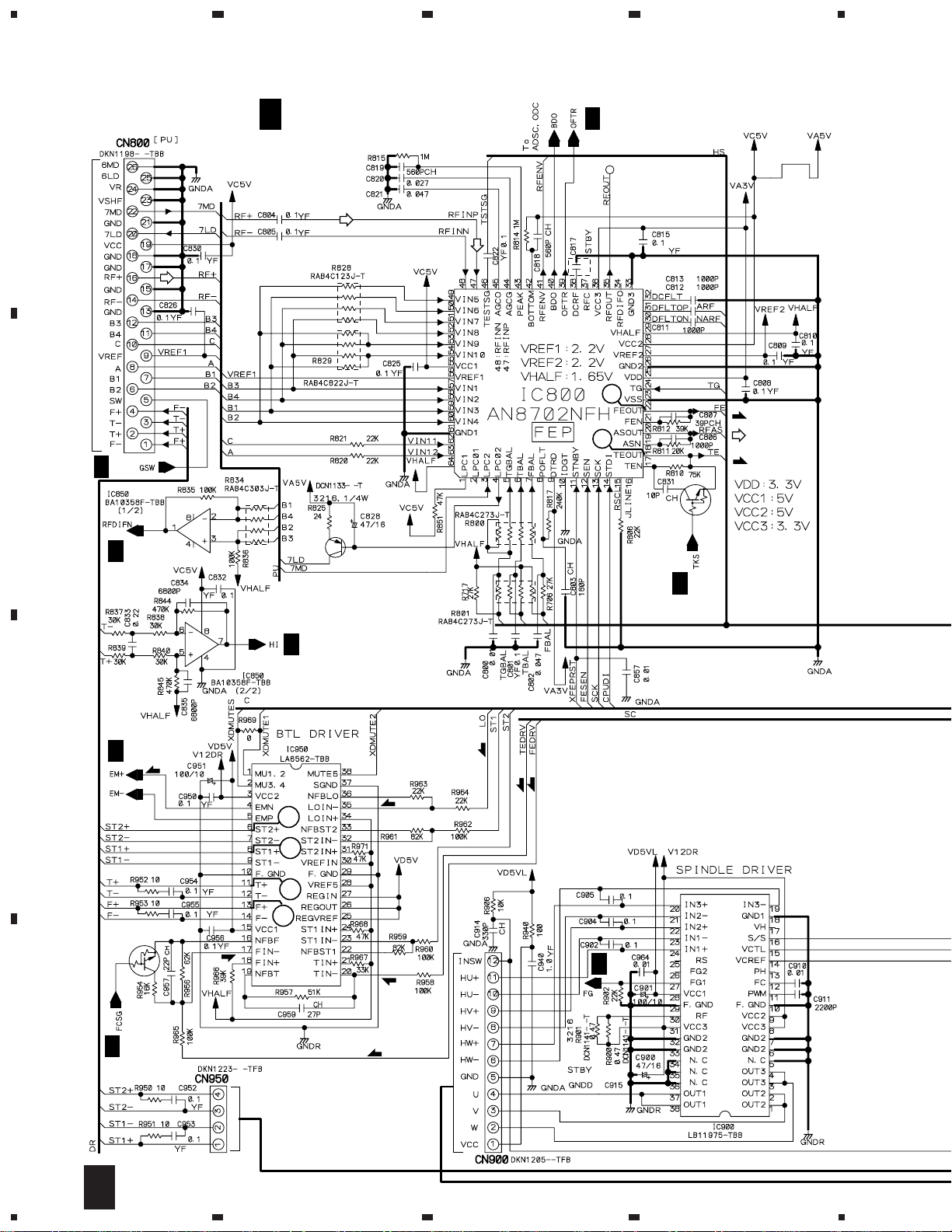
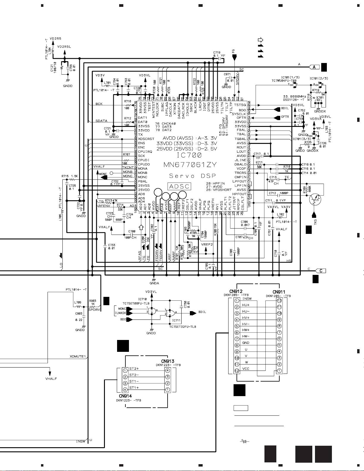
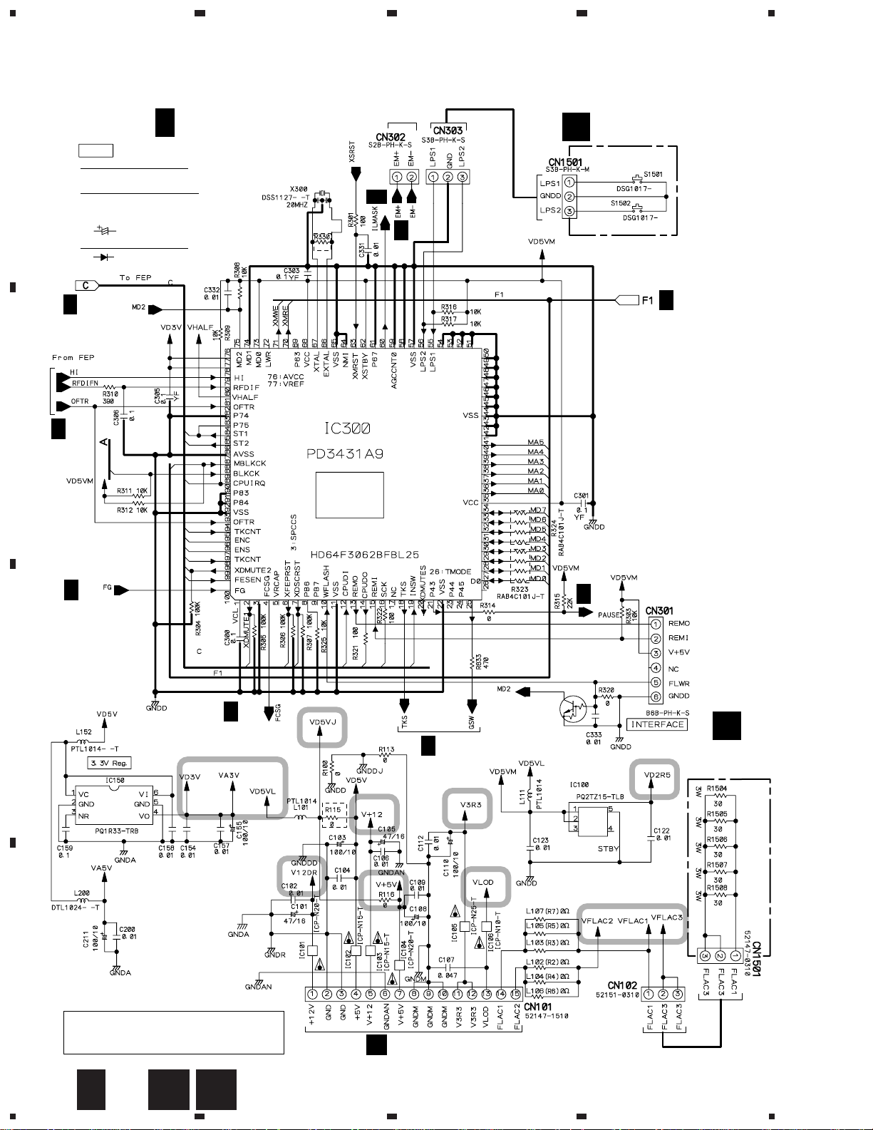
3.3 MAIN (1/4), SPCN and STCN ASSYS
4
A 1/4
MAIN ASSY
A 2/4
(DWX2161)
A
To PICKUP ASSY CN801
6
4
B
A 2/4
A 2/4
Q600
2SA1577
Q800
DTC124EUA
(FS)
(TS)
A 2/4
A 2/4
C
A 2/4
(L)
(L)
13
12
5
7
Q950
DTC124EUA
(FS)
(TS)
A 2/4
D
(FS)
(L)
(FS)
(TS)
A 2/4
16
1/4
A
1234
5
678
CDJ-1000
: RF SIGNAL ROUTE
(L)
: LOADING MOTOR SIGNAL ROUTE
(FS)
: FOCUS SERVO SIGNAL ROUTE
(TS)
: TRACKING SERVO SIGNAL ROUTE
A
A 3/4
B
11
1018
19
Q701
DTC124EUA
A 2/4
(TS)
(FS)
(L)
(TS)
(FS)
A 2/4
C
A 2/4
To
SPINDLE
STCN ASSY
C
(DWX2171)
MOTOR
(CN2220)
To
STEPPING
MOTOR
5
6
SPCN ASSY
B
(DWX2170)
NOTES
ALL RESISTORS ARE IN Ω
RS1/16S∗∗∗J
ALL CAPACITORS ARE IN µF
YF : CKSRYF
CH : CCSRCH
OTHERS : CKSRYB
7
: CEHAR
A
1/4
B
C
8
D
17
1
23
CDJ-1000
3.4 MAIN (2/4), FLRB and SLMB ASSYS
A 2/4
A
NOTES
ALL RESISTORS ARE IN Ω
RS1/16S∗∗∗J
ALL CAPACITORS ARE IN µF
YF : CKSRYF
CH : CCSRCH
OTHERS : CKSRYB
DIODE
: CEHAR
: 1SS355
MAIN ASSY
(DWX2161)
To LOADING
MOTOR
A 1/4
A 1/4
SLMB ASSY
E
(DWS1309)
4
SLMB ASSY
S1501 : CLAMP SW
S1502 : CLAMP SW
A 1/4
B
C
A 1/4
A 1/4
A 1/4
MECHA.
CONTROL
CPU
Q301
DTC124EUA
A 4/4
A 3/4
D
A 1/4
FLRB ASSY
(DWX2166)
D
CAUTION : FOR CONTINUED PROTECTION AGAINST
RISK OF FIRE, REPLACE ONLY WITH
SAME TYPE NO. ICP-N20, MFD BY ROHM
CO., LTD. FOR IC101 AND IC104.
18
2/4
A
1234
D E
CN2217
P
5
678
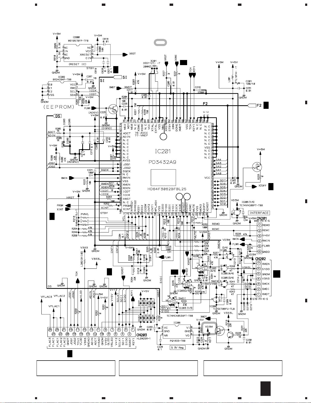
CDJ-1000
: The power supply is shown with the marked box.
A
A 3/4
A 3/4,4/4
Q201
DTC124EUA
A 3/4
1
B
Q202
DTA124EUA
A 3/4
A 4/4
SYSTEM
CONTROL
CPU
A 3/4
A 3/4
23
C
F
CN99
J 1/2
CAUTION : FOR CONTINUED PROTECTION AGAINST
RISK OF FIRE, REPLACE ONLY WITH
SAME TYPE NO. ICP-N15, MFD BY ROHM
CO., LTD. FOR IC102 AND IC103.
CN1101
5
CAUTION : FOR CONTINUED PROTECTION AGAINST
RISK OF FIRE, REPLACE ONLY WITH
SAME TYPE NO. ICP-N25, MFD BY ROHM
CO., LTD. FOR IC105.
6
Q203
Q204
Q203
DTC124EUA
CAUTION : FOR CONTINUED PROTECTION AGAINST
RISK OF FIRE, REPLACE ONLY WITH
SAME TYPE NO. ICP-N10, MFD BY ROHM
CO., LTD. FOR IC106.
7
2SC4081
A
2/4
8
D
19

1
CDJ-1000
3.5 MAIN (3/4) and MMCB ASSYS
A
23
17
4
A 2/4
A 2/4
A 3/4
MAIN ASSY (DWX2161)
A 3/4,4/4
A 2/4
A 2/4
B
A 2/4
C
A 4/4
14 16
15
A 1/4
A 2/4
D
20
3/4
A
1234
A 4/4
5
678
CDJ-1000
: The power supply is shown with the marked box.
NOTES
ALL RESISTORS ARE IN Ω
A 2/4,4/4
Q11
DTA124EUA
(D)
RS1/16S∗∗∗J
ALL CAPACITORS ARE IN µF
YF : CKSRYF
CH : CCSRCH
OTHERS : CKSRYB
: CEHAR
: PB AUDIO SIGNAL ROUTE
(D)
: DIGITAL DATA SIGNAL ROUTE
A
B
(GUARD GND)
A 4/4
A 2/4
A 2/4
CN202
CN1901
G
CN1802
I
CN1801
I
C
MMC CARD CONNECTOR
D
F
(BODY GND)
5
6
7
MMCB ASSY
(DWX2169)
3/4
A
F
8
21
1
CDJ-1000
3.6 MAIN ASSY (4/4)
23
4
A
A 2/4
A 2/4,3/4
INVERTER
5V → 3.3V BUFFER
A 3/4
B
C
A 3/4
A 2/4,3/4
D
A 3/4
22
4/4
A
1234
5
678
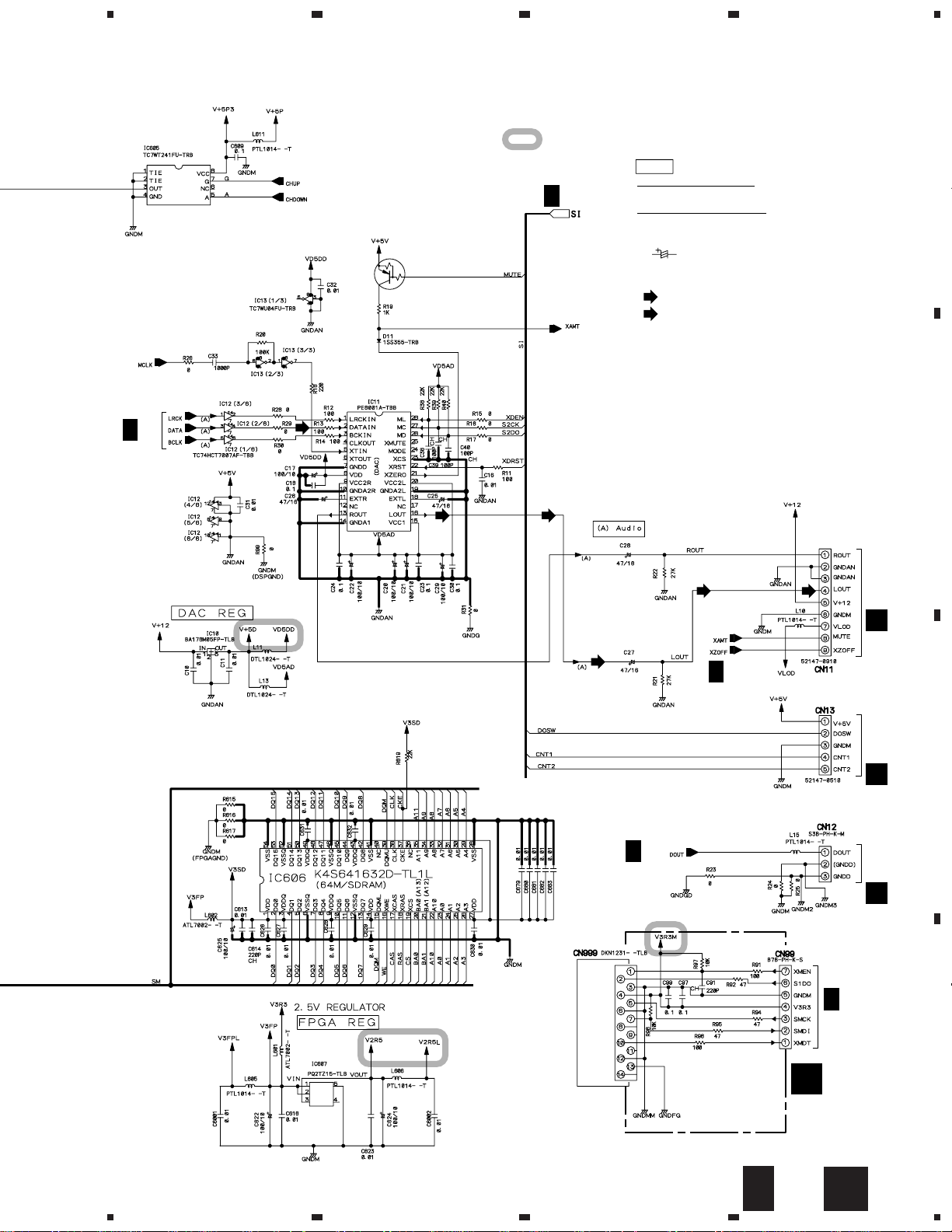
CDJ-1000
A 4/4
MAIN ASSY (DWX2161)
: The power supply is shown with the marked box.
(D)
: DIGITAL DATA SIGNAL ROUTE
NOTES
ALL RESISTORS ARE IN Ω
RS1/16S∗∗∗J
ALL CAPACITORS ARE IN µF
YF : CKSRYF
CH : CCSRCH
OTHERS : CKSRYB
: CEHAR
A
B
C
A 3/4
(D)
D
(D)
5
6
A 3/4
4/4
A
7
8
23
1
CDJ-1000
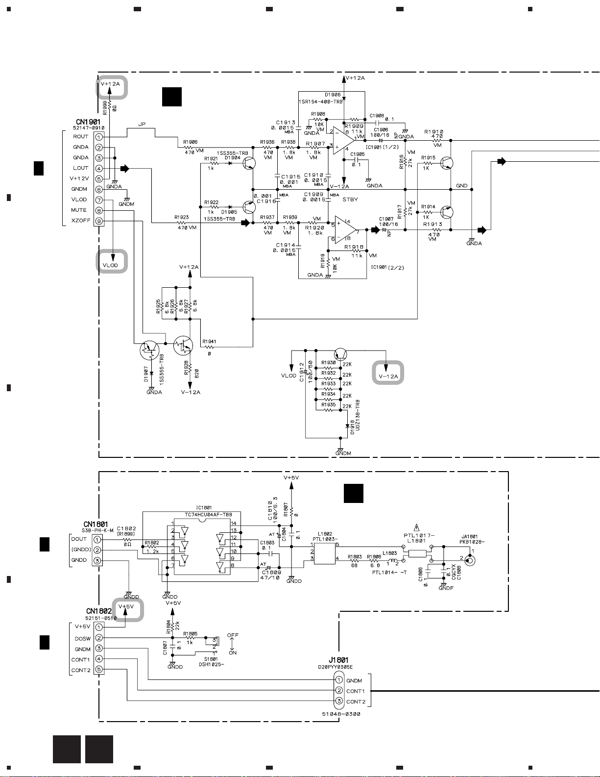
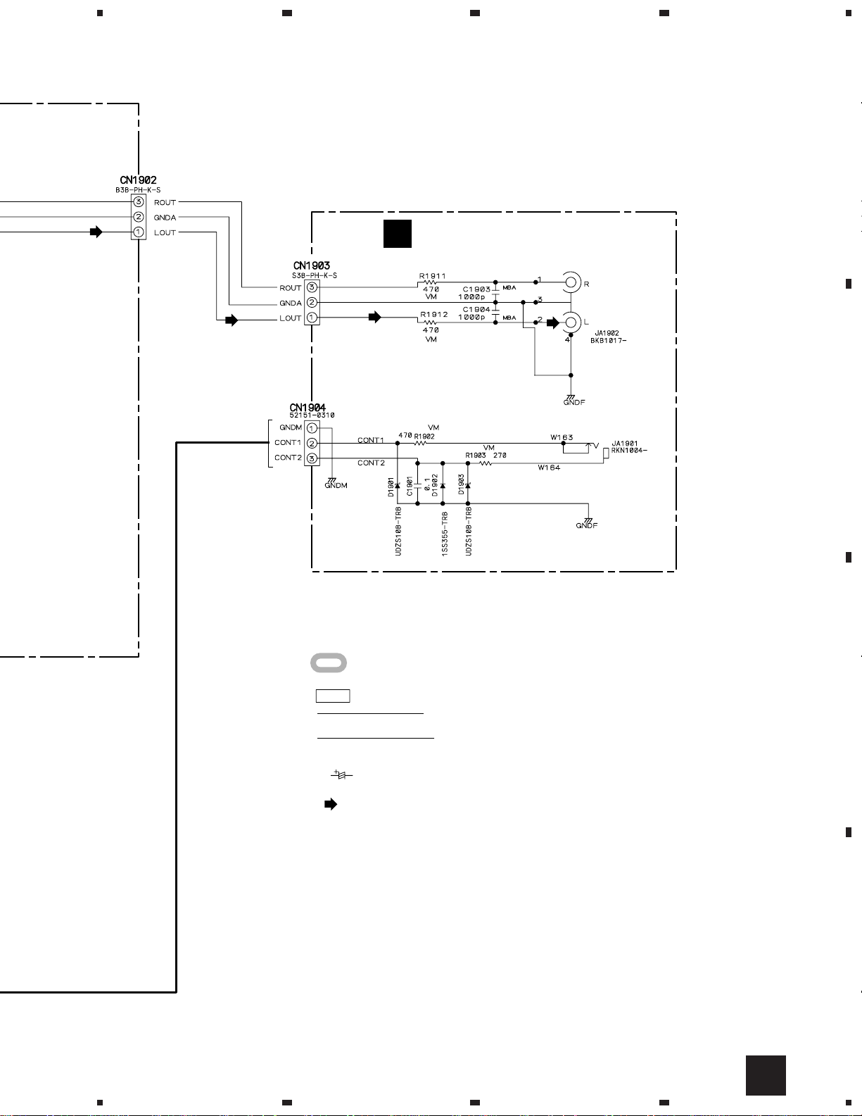
3.7 DABB, JACB and DOUT ASSYS
DABB ASSY
A
G
(DWX2162)
23
NJM4580D
4
A 3/4
CN11
B
Q1905
DTC124EUA
Q1906
DTA124EUA
Q1903
2SD2144S
Q1904
2SD2144S
Q1907
2SA1145
NJM4580D
Q1901
2SD2144S
Q1902
2SD2144S
C
DOUT ASSY
I
(DWX2164)
A 3/4
CN12
DIGITAL OUT
ON/OFF
DIGITAL
OUT
A 3/4
CN13
D
24
G
I
1234
5
678
CDJ-1000
A
JACB ASSY
H
(DWX2163)
AUDIO
OUT
: The power supply is shown with the marked box.
NOTES
ALL RESISTORS ARE IN Ω
RS1/16S∗∗∗J
ALL CAPACITORS ARE IN µF
YF : CKSRYF
CH : CCSRCH
OTHERS : CKSRYB
: CEHAR
: PB AUDIO SIGNAL ROUTE
CONTROL
B
C
D
H
5
6
7
8
25
1
23
CDJ-1000
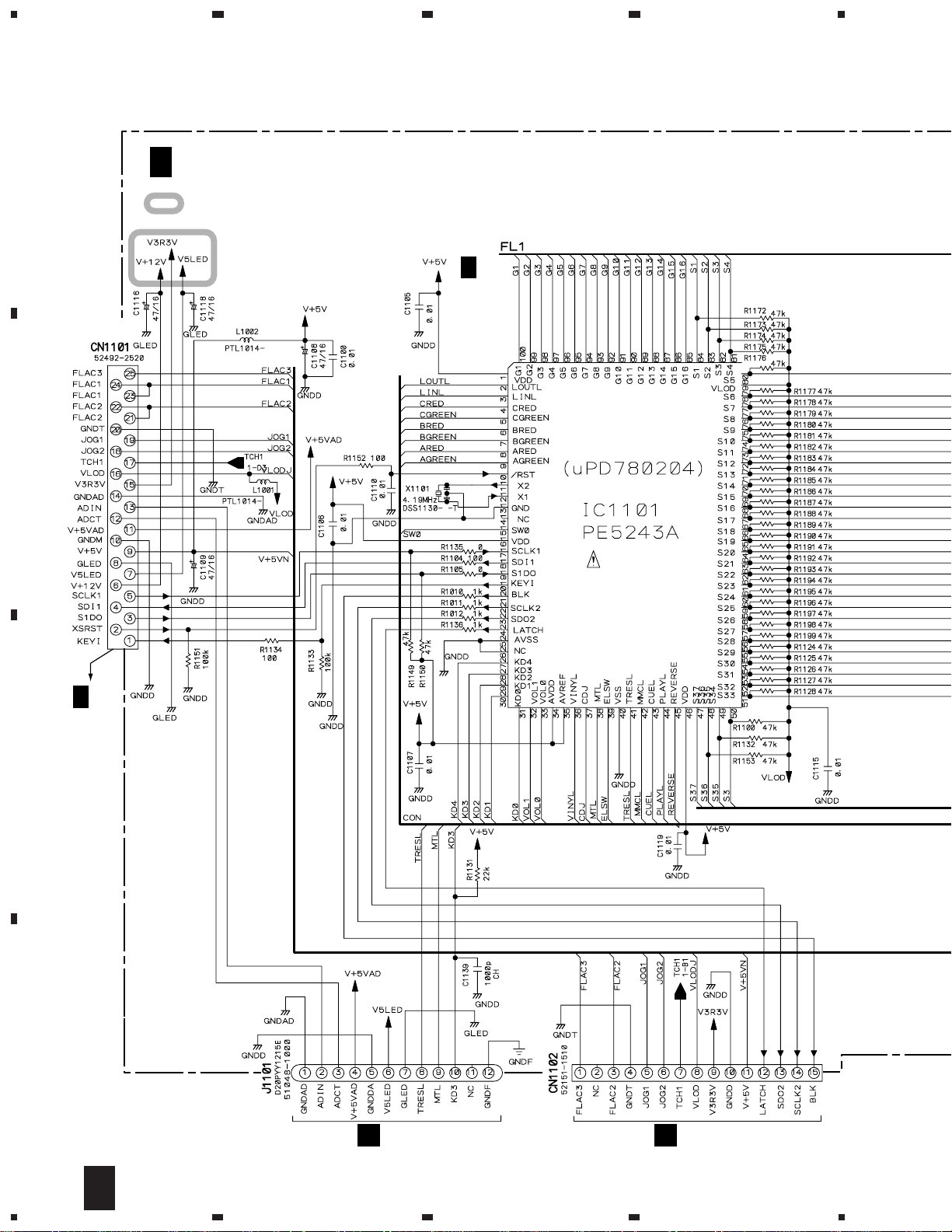
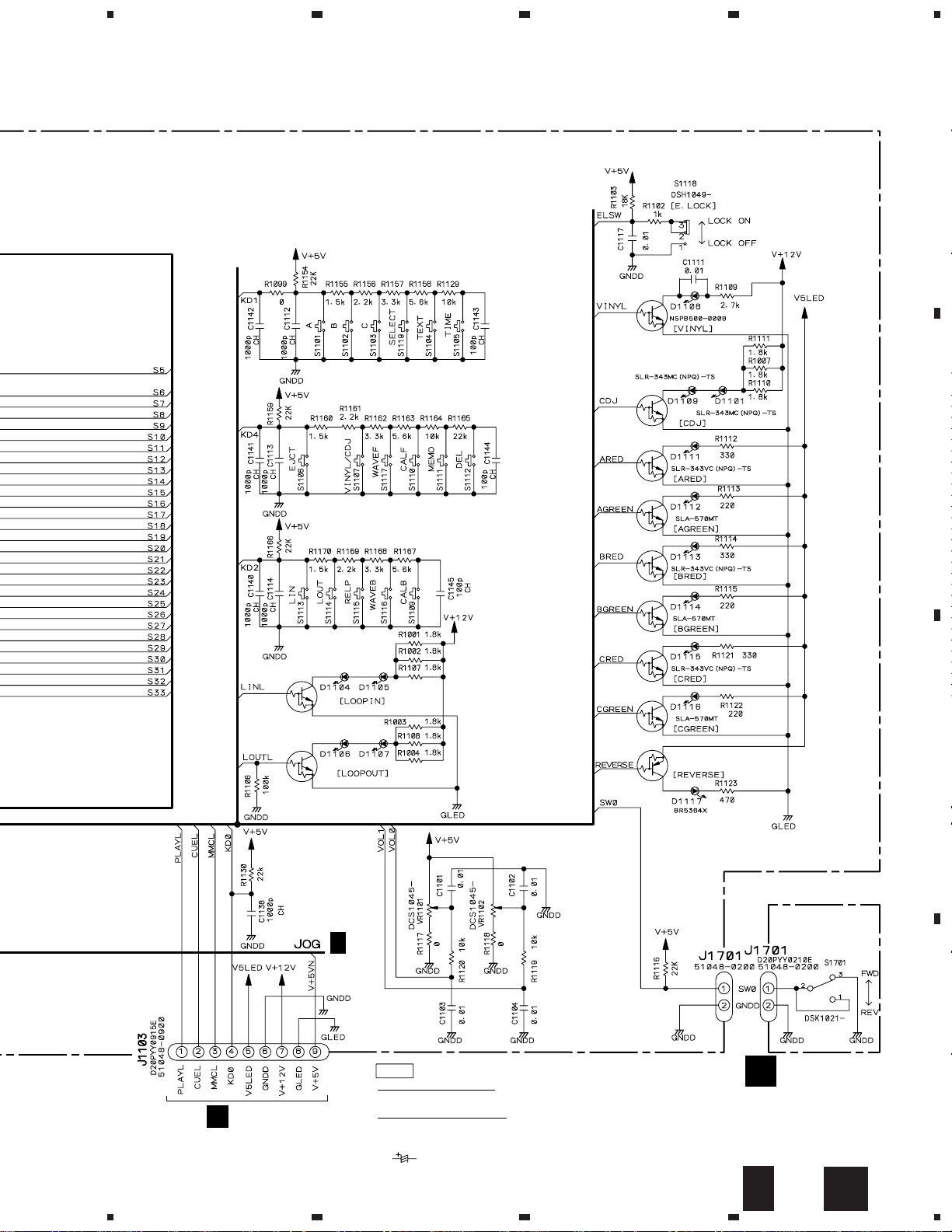
3.8 MFLB (1/2) and RSWB ASSYS
4
A
J 1/2
MFLB ASSY (DWG1548)
: The power supply is shown with the marked box.
J 2/2
DISPLAY
MICROCOMPUTER
B
A 2/4
CN203
C
D
M
CN1401
N
J1202
26
1/2
J
1234
5
SWITCHES
MFLB ASSY
S1101 : A
S1102 : B
S1103 : C
S1104 : DISPLAY
TEXT/WAVE
S1105 : TIME MODE
S1106 : 0 (EJECT)
S1107 : SELECT
VINYL – CDJ
S1109 : 2 CALL
S1110 : CALL 3
S1111 : MEMORY
S1112 : DELETE
678
CDJ-1000
S1113 : IN/REALTIME CUE
S1114 : LOOP OUT
S1115 : RELOOP/EXIT
S1116 : 2 WAVE
S1117 : WAVE 3
S1118 : EJECT LOCK
S1119 : SELECT
RSWB ASSY
S1701 : FWD – REV
S1101-S1103,S1113-S1115 : DSG1063
S1104-S1107,S1109-S1112 : ASG7013
S1116,S1117,S1119 : ASG7013
Q1103
DTC124EUA
Q1104
DTC124EUA
A
Q1101
DTC124EUA
Q1102
DTC124EUA
10k-B
D1104-D1107:
EMAY3864X-HM
10k-B
Q1106
DTC124EUA
Q1107
DTC124EUA
Q1108
DTC124EUA
Q1109
DTC124EUA
Q1110
DTC124EUA
Q1111
DTC124EUA
Q1112
DTA124EUA
B
C
L
5
CN1301
J 2/2
NOTES
ALL RESISTORS ARE IN Ω
RS1/16S∗∗∗J
ALL CAPACITORS ARE IN µF
YF : CKSRYF
CH : CCSRCH
OTHERS : CKSRYB
6
: CEHAR
RSWB ASSY
K
(DWS1310)
1/2
J
7
K
8
27
D
1
CDJ-1000
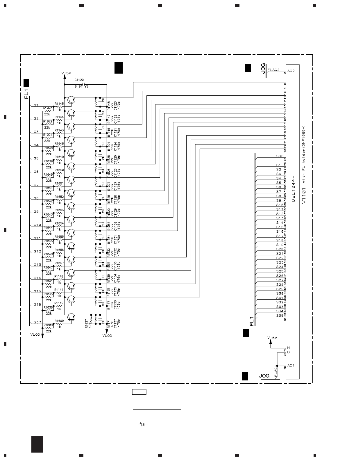
3.9 MFLB ASSY (2/2
A
J 1/2
Q1118
Q1117
Q1116
Q1008
Q1009
Q1010
23
J 2/2
MFLB ASSY (DWG1548)
J 1/2
4
B
C
Q1007-Q1017,Q1113-Q1118:
Q1011
Q1012
Q1013
Q1014
Q1015
Q1016
Q1017
Q1113
Q1114
Q1115
Q1007
2SC4081
FL INDICATOR TUBE
J 1/2
J 1/2
NOTES
D
28
2/2
J
1234
ALL RESISTORS ARE IN Ω
RS1/16S∗∗∗J
ALL CAPACITORS ARE IN µF
YF : CKSRYF
CH : CCSRCH
OTHERS : CKSRYB
: CEHAR
 Loading...