

Page 1

d
STEREO CAR CD RECEIVER
RADIO-TOCADISCOS DE CD ESTEREOFONICO PARA AUTOMOVIL
CDC-X126 YZ
INSTALLATION AND CONNECTIONS
INSTALACION Y CONEXIONES
INSTALLATION ET CONNEXIONS
INSTALLATION UND ANSCHLÜSSE
INSTALLAZIONE E COLLEGAMENTI
INSTALLATIE EN AANSLUITINGEN
A
A
ab cd
efgh i
b
B
a
c
C
c
b
a
9k 10k
d
D
8Z-KCG-908-01
981216ATM-OX
ENGLISH
SUPPLIED MOUNTING HARDWARE
FOR INSTALLATION → A
The letters are keyed to those in the instructions.
• Use only the supplied mounting hardware for a
safe and secure installation.
a Installation sleeve × 1 b Supporter × 1
c Mounting bolt × 1 d Nut × 1 e Screw × 1
f Washer × 2 g Spring washer × 2
h Lever × 2
i Screw × 5 (including 1 spare screw)
INSTALLATIONS
PRECAUTIONS
• This unit is designed for negative ground 12-V
DC operation only.
• Before making installations, make sure the
ignition switch is set to OFF and disconnect the
ground terminal of the car battery to avoid shortcircuiting.
• Install the unit where it will not hamper the driver
during driving.
• Install the unit where it will not injure the
passenger if there is a sudden stop, like an
emergency stop.
• Avoid installing the unit where it would be subject
to high temperatures caused by direct sunlight
or hot air from the heater, or where it should be
subject to dust, dirt or excessive vibration.
• Use only the supplied mounting hardware for a
safe and secure installation.
Consult with your nearest dealer if installation
requires the drilling holes or other modifications of
your car.
MOUNTING EXAMPLE
Installation in the dashboard
(The following example shows a typical installation,
however if you should make adjustments
corresponding to your specific car, consult your
nearest AIWA car audio dealer.)
Mounting angle adjustment
The mounting angle should be at the angle of 30
degrees or less.
REMOVING EXISTING RECEIVER
UNIT → B
If there is an installation sleeve for the receiver
unit already in the dashboard, it must be removed.
a Existing receiver unit b Installation sleeve
c Dashboard
BASIC INSTALLATIONS → C
Setting the step frequency → a
Before inserting the unit into the installation sleeve,
set the step frequency for your area with the
switch on the bottom of the unit.
9k: MW/AM 522 – 1,620 kHz (9-kHz steps)
LW 144 – 288 kHz (1-kHz/9-kHz steps)
FM 87.5 – 108 MHz (50-kHz steps)
10k: MW/AM 530 – 1,710 kHz (10-kHz steps)
LW 144 – 288 kHz (1-kHz/9-kHz steps)
FM 87.5 – 108 MHz (100-kHz steps)
(The switch is set at the factory to the 9k position.)
Mount the unit → b
a Dashboard b Fire wall
Note → c
Bend the claws according to the thickness of the
dashboard.
When removing the unit from the installation
sleeve → d
If you need to remove the unit from the installation
sleeve, proceed as follows.
1. Remove the rear supporter b from the unit.
2. Remove the control panel from the unit. (Refer
to the operating instructions.)
3. Remove the trim plate a by pushing the upper
and lower parts of the plate in the direction of
the arrow.
4. Insert two levers h into the pair of grooves on
both sides of the unit, and pull the levers toward
you to remove the unit from the installation
sleeve.
INSTALLATIONS WITHOUT USING
THE SLEEVE → D
In the case of Toyota cars, etc., first remove the
existing car stereo and then install the unit in its
place.
1. Remove the trim plate a by pushing the upper
and lower parts of the plate in the direction of
the arrow.
2. Attach the existing mounting bracket b (not
supplied) to the unit. Make sure to use the
screws (M5 × 6 mm) i. Using longer screws
may damage the unit.
Caution
Do NOT use the supplied screw e to attach the
mounting bracket.
ESPAÑOL
PIEZAS DE FERRETERIA
SUMINISTRADAS PARA LA
INSTALACION → A
Las letras en un círculo dentro en el texto
corresponden a las de los dibujos a continuación.
• Utilice sólo las piezas de ferretería suministradas
para que la instalación sea más firme y segura.
a Manguito de instalación × 1 b Soporte x 1
c Perno de montaje × 1 d Tuerca × 1
e Tornillo × 1 f Arandela × 2
g Arandela de resorte × 2 h Palanca × 2
i Tornillo × 5 (incluye un tornillo de repuesto)
INSTALACION
PRECAUCIONES
• El aparato fue diseñado para funcionar sólo con
CC, con una conexión a tierra negativa de 12V.
• Antes de hacer la instalación, compruebe que el
interruptor de encendido está en OFF y
desconecte el terminal a tierra de la batería del
coche para evitar un cortocircuito.
• Instale el aparato en un lugar donde no pueda
molestar al conductor durante la conducción.
• Instale el aparato donde no pueda provocar
heridas al pasajero en caso de frenado repentino,
por ejemplo en una parada de emergencia.
• No instale el aparato en un lugar expuesto a
altas temperaturas provocada por los rayos
directos del sol o al aire caliente de la calefacción,
o donde puede estar expuesto al polvo, suciedad
o vibración excesiva.
• Utilice sólo las piezas de ferretería suministradas
para la instalación para hacerlo de forma seguro
y protegerlo contra accidentes.
Consulte con su concesionario más cercano si la
instalación necesita el taladrado de orificios u
otras modificaciones en su coche.
EJEMPLO DE INSTALACION
Instalación en el
(Los siguientes ejemplos muestran una instalación
típica aunque es necesario modificar esta instalación
de acuerdo a las condiciones particulares de su
coche; consulte con su concesionario de audio
para coche de AIWA más cercano.)
Ajuste de ángulo de instalación
El ángulo de instalación debe ser de 30 grados o
menos.
DESMONTAJE DE LA RADIO DEL
COCHE → B
Si hay un manguito de instalación para la radio del
coche en el tablero de controles, deberá desmontarlo.
a Radio del coche b Manguito de instalación
c Tablero de controles
INSTALACION BASICA → C
Ajuste de los pasos de frecuencia → a
Antes de instalar el aparato en el manguito de
instalación, ajuste el los pasos de frecuencia de
acuerdo a la zona donde lo va a utilizar, utilizando
el botón en la parte inferior de la unidad.
9k: MW/AM 522 – 1.620 kHz (pasos de 9 kHz)
LW 144 – 288 kHz (pasos de 1 kHz/9 kHz)
FM 87,5 – 108 MHz (pasos de 50 kHz)
10k: MW/AM 530 – 1.710 kHz (pasos de 10 kHz)
LW 144 – 288 kHz (pasos de 1 kHz/9 kHz)
FM 87,5 – 108 MHz (pasos de 100 kHz)
(El interruptor se ajustó en fábrica a la posición de 9k.)
Instale el aparato → b
a Tablero de controles
b Panel del compartimiento del motor
Nota → c
Doble las garras de acuerdo al espesor del tablero
de controles.
Desmontaje del aparato de su manguito de
instalación → d
En el caso de que fuera necesario desmontar el
aparato de su manguito de instalación, utilice el
siguiente procedimiento.
1. Desmonte el soporte trasero b del aparato.
2. Desmonte el panel de control del aparato. (Lea
las instrucciones de funcionamiento.)
3. Desmonte la placa de adorno a empujando
las partes superior e inferior de la placa en el
sentido de la flecha.
4. Coloque dos palancas h en el par de ranuras
a ambos lados del aparato y tire de las palancas
para desmontar el aparato de su manguito de
instalación.
INSTALACIONES SIN USAR EL
MANGUITO → D
En el caso de los coches Toyota, etc., primero
desmonte el estéreo de coche existente y después
instale el aparato en su lugar.
1. Desmonte la placa de adorno a empujando
las partes superior e inferior de la placa en el
sentido de la flecha.
2. Instale la ménsula de montaje existente b (no
incluida) en el aparato. Asegúrese de utilizar
los tornillos (M5 × 6 mm) i. El uso de tornillos
más largos puede dañar el aparato.
Precaución
NO utilice el tornillo suministrado e para instalar
la ménsula de montaje.
tablero de controles
Page 2
ENGLISH
ESPAÑOL
C
1BACK UP B
D
A
C
2AUTO ANT
3ACC
4GROUND
5678
B
15A
0.5A
D
CONNECTIONS
PRECAUTIONS
Precaution on making connections
Before connecting, make sure that the ignition
switch is set to OFF, and remove the 3 terminal
of the battery to avoid short circuits.
Caution
Make correct connections as illustrated in the
connection diagram.
Never use the 3 cord of each speaker in common.
When replacing the fuse, be sure to use one
whose amperage rating is identical. Use of a fuse
of higher amperage may cause serious damage
to the unit.
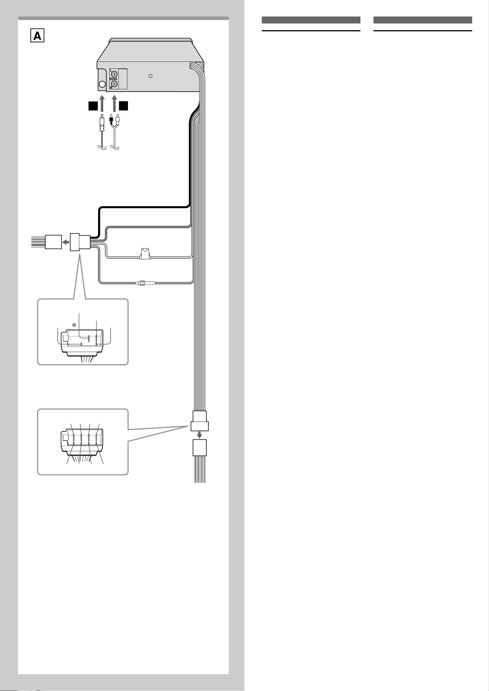
CONNECTION DIAGRAM → A
A From antenna
B From optional power amplifier’s input jack
for rear channel
C To the ISO connector of vehicle (power
supply)
Note
If you want to use the leads with the ISO connector
removed, make sure to connect each lead to the
correct terminal according to the list of colors of
leads below.
Colors of leads
1 Yellow (battery lead to be connected to the
backup terminal from which power is always
supplied.)
2 Blue (power antenna lead to be connected to
the terminal of the control relay switch for
vehicles equipped with a power antenna. This
lead is not used for vehicles with manual or
semiautomatic antennas. When you use
optional power amplifiers with the unit, connect
this lead to the remote terminal of the amplifier.)
3 Red (ACC lead to be connected to the terminal
from which the power is supplied when the
ignition switch is set to ACC.)
4 Black (ground lead to be connected to vehicle
(metal) body.)
D To the ISO connector of vehicle (speaker
connection)
Note
If you want to use the leads with the ISO connector
removed, make sure to connect each lead to the
correct terminal according to the list of colors of
leads below.
Colors of leads
5 Violet (Rear right 2)
6 Gray (Front right 2)
7 White (Front left 2)
8 Green (Rear left 2)
9 Violet/black (Rear right 3)
0 Gray/black (Front right 3)
! White/black (Front left 3)
@ Green/black (Rear left 3)
Notes
• Use speakers with an impedance of 4- to 8ohms, and with adequate power handling
capacities. Otherwise, speakers may be
damaged.
• Do NOT connect the speakers in parallel.
• Do NOT connect the terminals of the speaker
system to the car chassis.
CONEXIONES
PRECAUCIONES
Precauciones al realizar las conexiones
Antes de hacer las conexiones, verifique que la
llave de encendido está en la posición OFF y
desconecte el terminal 3 de la batería del coche
para eliminar la posibilidad de un cortocircuito.
Precaución
Haga las conexiones correctamente de acuerdo
al diagrama de conexiones.
No una los cables 3 de los distintos altavoces.
Cuando tenga que cambiar un fusible, utilice otro
que tenga las mismas especificaciones. El uso de
un fusible con un amperaje mayor puede provocar
daños graves en el aparato.
DIAGRAMA DE CONEXIONES → A
A De la antena
B De la toma de entrada del amplificador de
potencia opcional para el canal trasero
C Al conector ISO del vehículo (fuente de
alimentación)
Nota
Si desea utilizar los cables con el conector ISO
desmontado, verifique de conectar cada cable al
terminal correcto de acuerdo a la lista de colores
de los cables a continuación.
Colores de los conductores
1 Amarillo (conductor de batería conectado al
terminal de respaldo que siempre tiene
corriente.)
2 Azul (conductor a antena eléctrica conectado
al terminal del interruptor de relé de control
para vehículos con antena eléctrica. Este
conductor no se utiliza para vehículos con
antenas manuales o semiautomáticas. Cuando
se utilizan amplificadores de potencia
opcionales con este aparato, conecte el cable
al terminal remoto del amplificador.)
3 Rojo (conductor ACC conectado al terminal
que suministra corriente cuando la llave de
encendido está en ACC.)
4 Negro (cable a tierra conectado al vehículo
(metal) de la carrocería.)
D Al conector ISO del vehículo (conexiones
de altavoces)
Nota
Si desea utilizar los cables con el conector ISO
desmontado, verifique de conectar cada cable al
terminal correcto de acuerdo a la lista de colores
de los cables a continuación.
Color de los cables
5 Violeta (Trasero derecho 2)
6 Gris (Delantero derecho 2)
7 Blanco (Delantero izquierdo 2)
8 Verde (Trasero izquierdo 2)
9 Violeta/negro (Trasero derecho 3)
0 Gris/negro (Delantero derecho 3)
! Blanco/negro (Delantero izquierdo 3)
@ Verde/negro (Trasero izquierdo 3)
Notas
• Utilice altavoces con una impedancia de 4 a 8
ohmios y con suficiente capacidad para controlar
la potencia. De lo contrario pueden dañarse los
altavoces.
• NO conecte los altavoces en paralelo.
• NO conecte los terminales del sistema de
altavoces en el chasis del coche.
90!
@
 Loading...