

Page 1
Video 8
©1986 by Sony Corporation
Hondycom
Page 2
OWNER’S RECORD
WARNING
The model and serial numbers are located on
the bottom.
Record the serial number In the space provided
below. »
Refer to these numbers whenever you call upon
your Sony dealer regarding this product
Model No. CCO-V1 Serial No_______________________
NOTES
• For “once-only” events, it is storngiy
recommended to have a trial run to check that
everything is working perfectly.
• Television programs, films, video tapes and
other materials may be copyrighted.
Unauthorized recording of such material may
be contrary to the provisions of the copyright
laws.
• For using the recorder abroad, see page 34.
This unit uses 8mm video format cassettes. It
records in the SP mode (approximately
1.43cm/scond) arKd can play back in the SP
mode and the LP mode (approximately
0.72cm/second).
The quality of the playback picture in the LP
mode, however, will not be as good as that Tn
the SP mode.
To prevent fire or shock hazard, do
not expose the unit to rain or
moisture.
To reduce the risk of fire, do not
remove cover (or back).
This symbol is intended to alert the
user to the presence of important
operating and maintenance
(servicing) instructions in the
literature accompanying the
appliance.
INFORMATION
This equipment generates and uses radio
frequency energy and if not installed and used
properly, that is, in strict accordance with the
manufacturer’s instructions, may cause
interference to radio and television reception. It
has been type tested and found to comply with
the limits for a Class B computing device in
accordance with the specifications in Subpart J
of Part 15 of FCC Rules, which are designed to
provide reasonable protection against such
interference in a residential Installation. However,
there is no guarantee that interference will not
occur in a particular installation.
If this equipment does cause interference to
radio or television reception, which can be
determined by turning the equipment off and on,
the user is encouraged to try to correct the
interference by one or more of the following
measures:
Reorient the receiving antenna
Relocate the equipment with respect to the
receiver
Move the equipment away from the receiver
Plug the equipment Into a different outlet so
that equipment and receiver are on different
branch circuits.
If necessary, the user should consult the dealer
or an experienced radiortelevision technician for
additional suggestions. The user may find the
following booklet prepared by the Federal
Communications Commission helpful:
“How to Identify and Resolve Radio-TV
Interference Problems”. This booklet is available
from the U.S. Government Printing Office,
Washington, DC 20402, Stock No.
004000003454.
Page 3
TABLE OF CONTENTS
Location and function of controls_____________
Attaching the grip
Power sources
Cassette care
Camera recording...........................................................................
Recording date or time
Camera recording using the Remote Commander..
Use of an optional microphone
.................................................
.....................................................
.......................................................
№91^
..................
.................................................
..............................................
RECORDER OPERATION
Connection for viewing playback picture.
Playback of a recorded tape..........................................
Various playback modes...............................................
TV program recording...................................................
Use of the counter
Tape editing..................................................................
GENERAL
Notes on moisture condensation.
Precautions..................................................
Using your recorder abroad
Specifications...............................................
Troubleshooting
Check list before recording
HINTS FOR BETTER SHOOTING ,
........................................................
..........................
...........................................
.......................
....
33
34
M:
35
36
37
38
Page 4
n
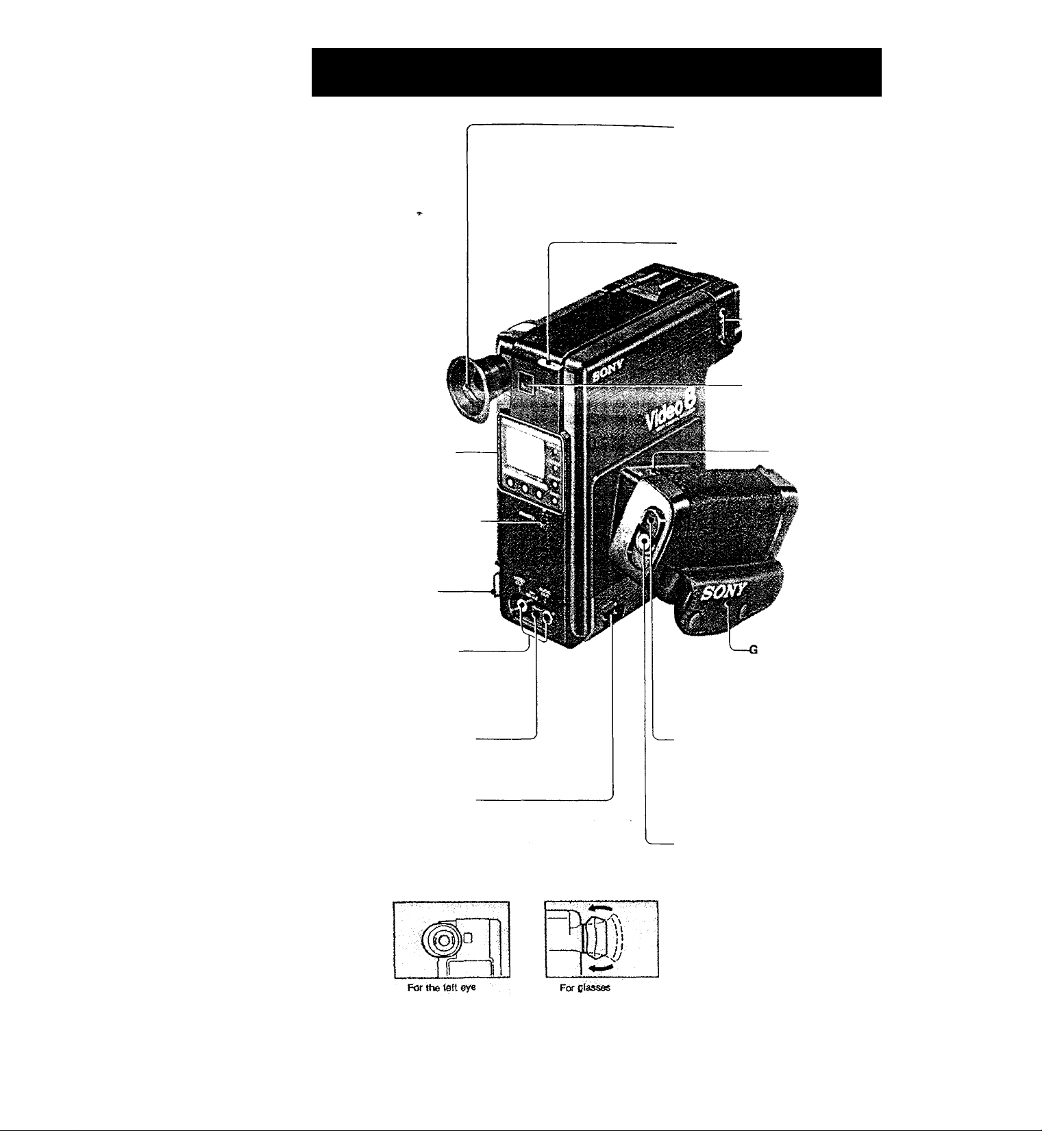
LOCATION AND
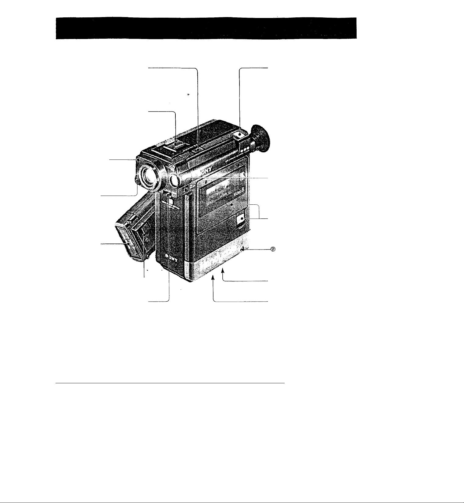
FUNCTION OF CONTROLS For details, refer to the pages indicated next to each item.
Optical viewfinder
The Indicators Inside the viewfinder light or
Wink during camera recording.
The eyecup In the photo Is attached for the
right eye.
For the left eye, detach the rubber eyecup
arki attach It as illustrated below.
For glasses, fold the eyecup as Illustrated
below.
Shoulder strap loop
MIC (microphone) jack and
MIC DC OUT jack
Connect an optional microphone.
STANDBY button
Press this button to enter the
recording pause mode.
Press again to turn off the power.
DATA DISPLAY SYSTEM
(DDS) ® ©
REMOTE connector (5-pin) O
Connect the wired Remote
Commander RM-87 (supplied).
The optional RM-E100V editing
TOntroller can be also connected here
Shoulder strap loop
AUDIOAfIDEO OUT jacks
(phono type)®
Connect to an RFU-88UC RFU
adaptor or an audlo/video Input of
TV/monItor Of a VCa
RFU DC OUT
Connect to an RFU-88UC RFU
adaptor.
AV (audio/video) input jacks
(miniphono type) ®
Connect to audloAfideo outputs of a TV or
another VCR with the supplied connecting cable.
CRIP RELEASE button O
rip strap O
Adjust this strap so that your
fingertips can easily manipulate the
REC START/STOP button.
ROWER ON/OFF switch
The unit cannot be operated when
the switch is set to OFF (the shutter
Is closed) except for the DDS (DATA
DISPLAY SYSTEM).
REC (recording) START/STOP
button ©
Eyecup adjustment
Page 5
WHITE BALANCE
switch
•¿¡c: Artificial light ptKloors)
Sunlight (outdoors)
Accessoty shoe
Attach an optional external
microphone or video light (up to
500g, 1 lb).
Tally lamp (red)
Lights Up during camera
recording.
Microphone
Skylight window
Supplies light for the Indicators In
the viewfinder through this opening.
BACK LIGHT button ©
While shooting a backlit scene, keep
pressing this button.
Cassette holder and EJECT
button ©
Battery-
compartment О
Insert an NP-22 battery
pack, ACP-80UC ac pack
or DCP-80 dc pack.
ВАТТ (battery) EJECT button О
FOCUS switch
Set the switch according to the
distances.
Approx. 1.2-2.0 m
li: Approx. 1.7-42 m
rr-i
(3.9-6.6 feet)
(5.6-13.8 feet)
Approx. More than 2.9 nti
(9.5 feet)
............... ..........................................
‘
|ЯИ|ИД|Д11
Earphone jack
Tripod receptacle
Uthium battery compartment
©
Insert the supplied lithium battery to
activate the DOS.
EDIT switch Cinside the
bottom panel) ©
Counter 1/2 (display) selector
(inside the bottom paneO €)
‘ШШШШ
X < X ‘S -
I'p
Page 6
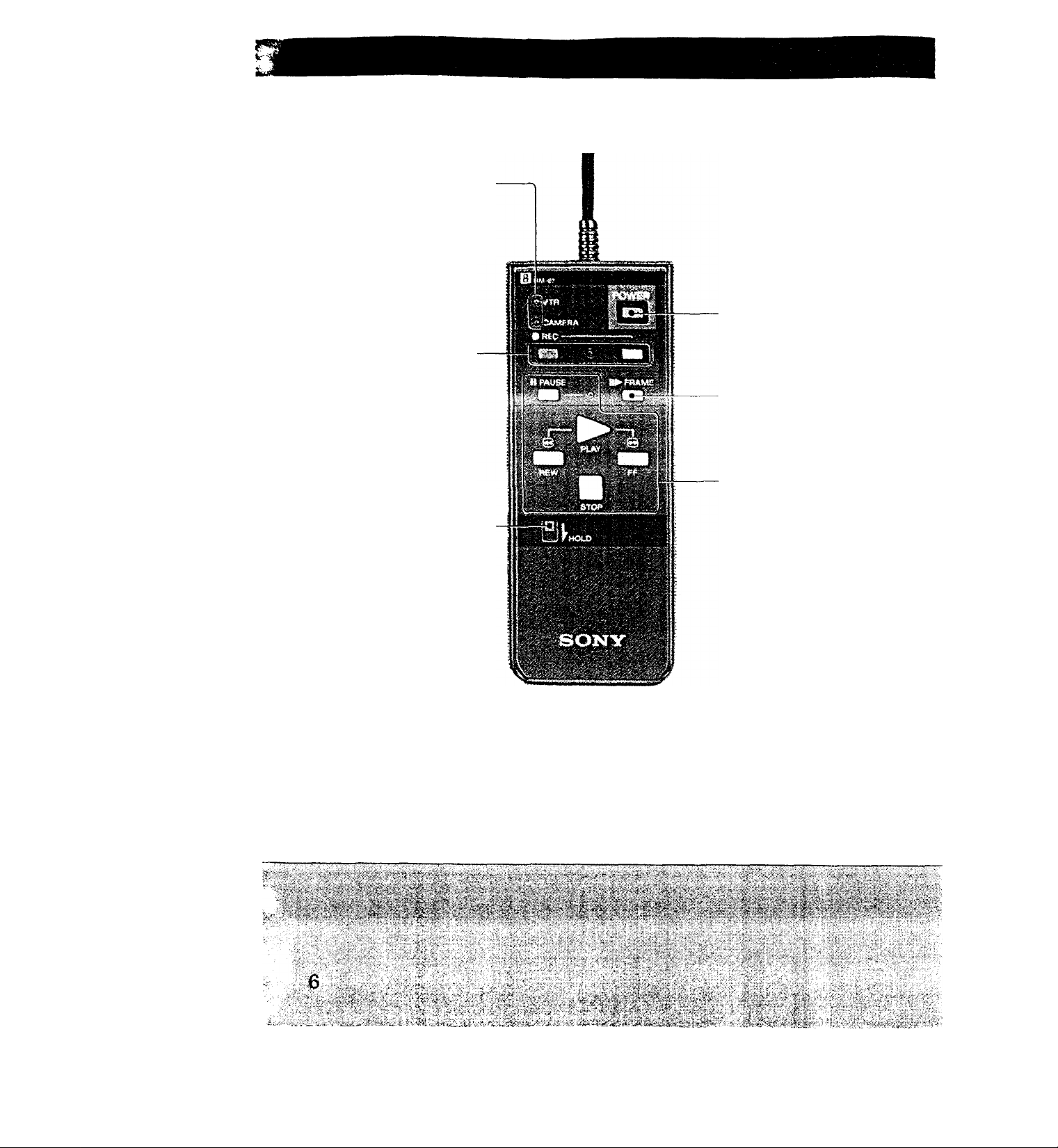
VTR and CAMERA Indicators
VTR Lights when the POWER of the
Commander Is pressed.
CAMERA: Lights during caSwa recording
VTR and CAMERA Light during camera
recording using the Commander.
REC • (recording) buttons and indicator
Press to start recording.
HOLD button
Press It down when the Commander Is rxit
In use.
The buttons of the Commander will not
function.
---------------------------------------
POWER switch
11^ FRAME button
Press this button In pause mode to view
Stop-action advance picture. To view a 1/30
slow picture, keep pressing.
Tape transport buttons
► PLAY, -4 4 REW (rewind), ►► FF
(fast-frxward), ■ (stop), || PAUSE
Page 7
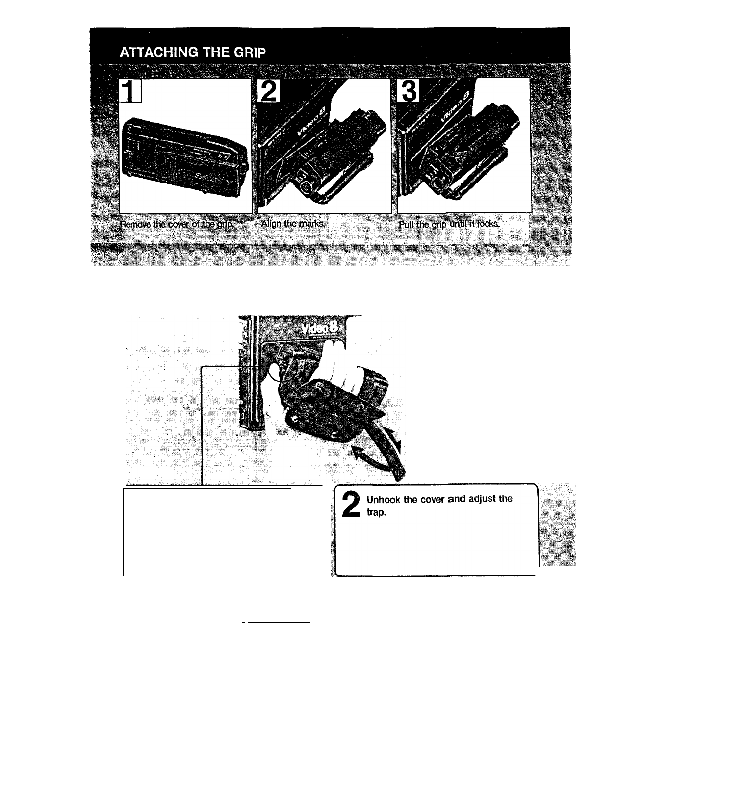
ADJUSTING THE GRIP STRAP
Position your right hand so that
-I
1 your fingertip can easily
1
manipulate the POWER ON/OFF
.
switch.
s
J. :<M.u. f.
button In the direction ot the
arrow while sliding the grip off.
SiiiKt
....................^....................................
_
/, j ¥o avoid Short drcurt, keep
.....................................
""\
.......
....................................................
terminafs of the grip when it la
detacheii w*'^ battery
.insefted>.r ^ / - ■•
^ t i f ^ r
' pack
' "■'' ■’
.......
M-.-
'^ r*‘ '■■ J«-
’ '
_.
Page 8
POWER SOURCES
•- . * X'*' •• X-*'VU'r '■ <
i, v.vvWiS3^^'4'5?y4'
•■ *■''. ■* x^iy sVx
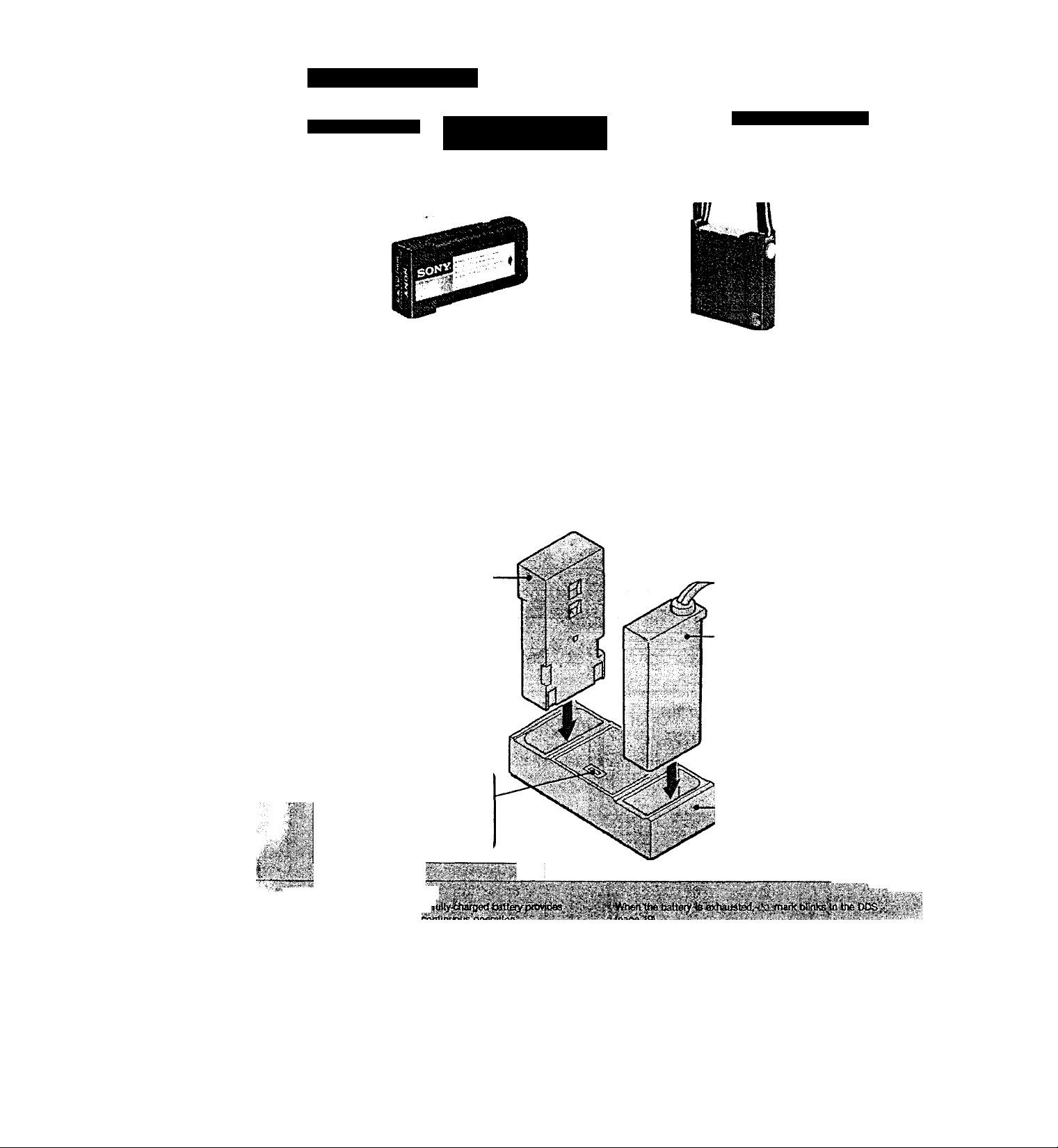
Battery pack NP-22
BATTERY PACK
Before inserting the battery pack NP-22, charge it as ctescribed beiow.
How to charge
The charging time is about 1 hour.
Battery pack NP-22-
RechatigeaWe battery pack NP-4000
(Used with DC pack)
to an ac outlet (120V)
-AC pack ACP-80UC
■,'M'
-
The CHARGE lamp will
go out when the battery
is fully charged.
BatteiVJife
As.ttt? wit consume» ilowefeverTin the stahdby mtxJe^lbe . /«the tinit is feft in such a cpndftlor>. the installed cassette
' ,3f theba^iyi)acki?,ttof itiltyehafoedorif itistised^oold -• SQi^jtacelheWtfefv with a fully teamed bna as soon as
place,^ (^»ratirsg iime to shortened. ^ ^ < T’^posstefe:«
:8
~ -y'^:..5:>? V '■;
■ Battery charge adaptor
BCA-70
S^:
Page 9
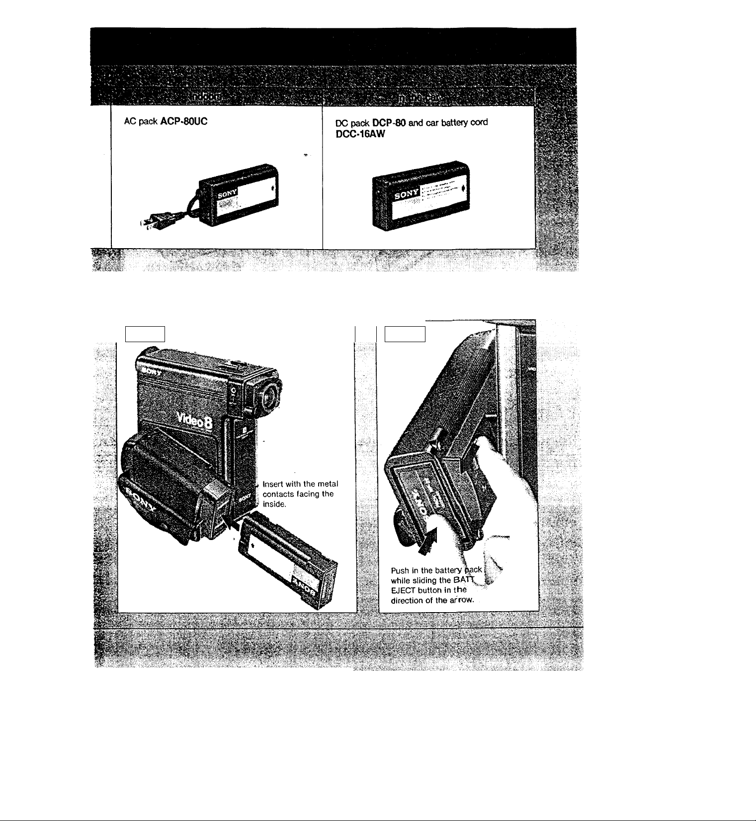
Insertion
Removal
llilipwiliaig®
■; - ■ !, .5 .;/^i.:-"' - i
■
.....
„,.-; ' '■', ;-vi-'i'.
...
V<o>S^ »f'iy -f^v- vfe .<«
Page 10
©
©
.
PM
.nn.nr
6
■UU-U 3
PATH f~fiME HCOUNTE^
® @ @
The date in the display window
will be recorded as follows.
@
HME }c
The time in the display window
will be recorded as follows.
'iSj
18
To stop recording date or time
Press COUNTER. Camera recording will continue.
»Si
Page 11
THREE MODE OF OPERATION
□
■ the apptxjpriate power switch (button) according to your purp^.
Operating mode CAMERA mode VTR mode
Purpose
Switch to be
pressed
Indicators in the
DOS
S'V Mote on power source
'¿'^4^sconri^ing the.'power source or removing iheS
i>attery/AC/DC pack during recordirrg or playback
, may danrage the inserted cassette tape.
If this Is done by accident, supply the power again
* Immediately.
Camera recording
REC START/STOP
or STANDBY
CAM . VTR
Playback, TV
program recording
POWER switch of
the Remote
Commander
* *
VTR/CAMERA mode
Camera recording and playback operated
with the Remote Commander
POWER switch of the Remote
Commander and STANDBY
CAM + I VTR I
!4V%tr3s$-
'fîM.'-tfV'ii
ixi¥»iaKL«iaii
11
Page 12
,_ ^
-----------------------------------
'
...........
.......................... " »." "’\
1
" ' ’V
1 Press down
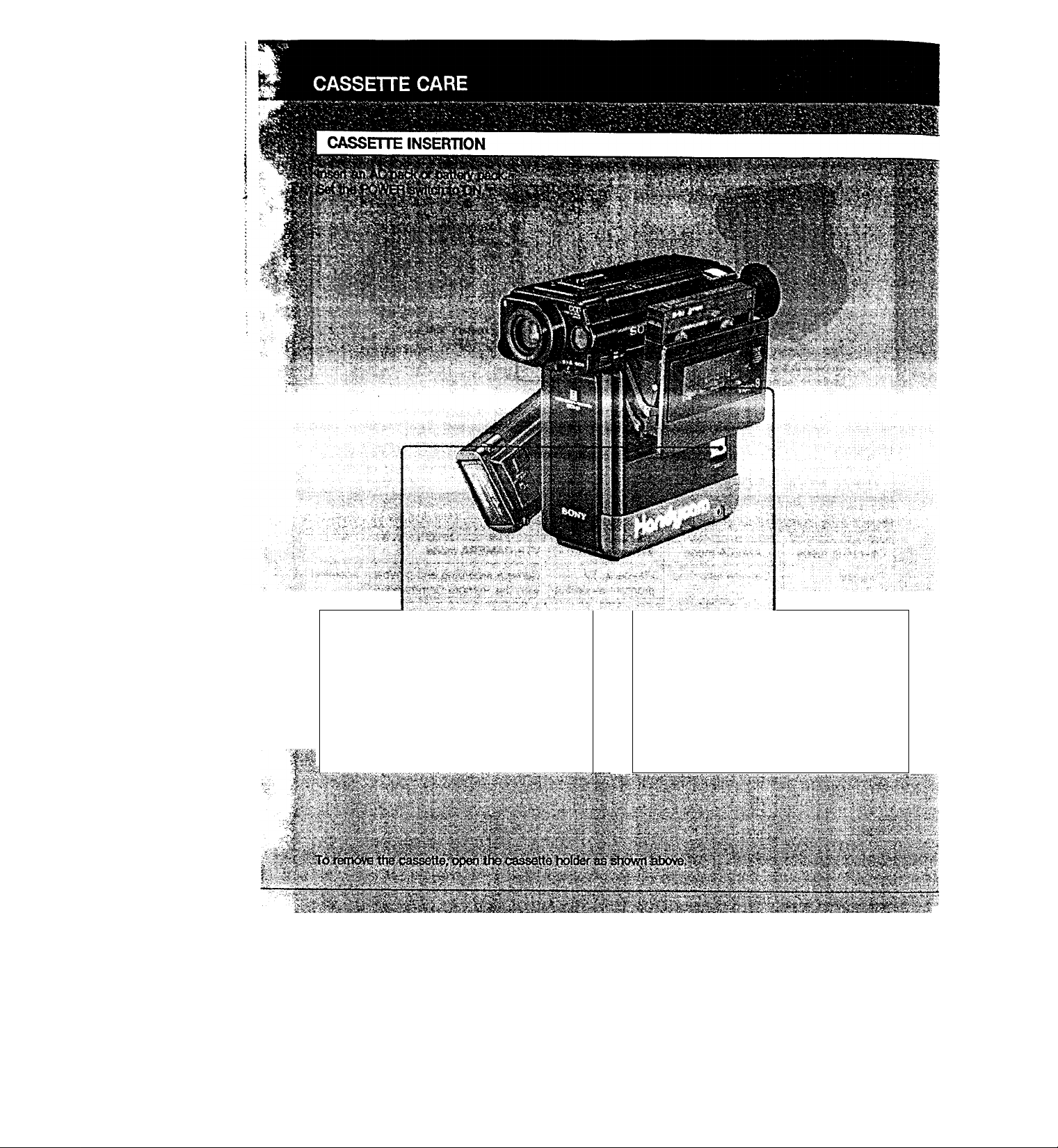
■ Insert the cassette with the
window and the arrow facing the
outside.
•1
• *1
k__
' x;:^^''>5-' >7rj t///>;" ^ -^<^r;. %'$: -'-yf'a ,-,//^i\% r ^ ^ ■‘^’ ./ '■«; - j.f^~t */y^/’•'i'Y. ,,, '
•' 7 V'/.' ^ ■'■'I'.':'''"/. ~\ .'/'^ . '. •''■ ; •j^-.v^'// y." ^ ■■ ' ‘■'■‘•'X%
," :Y:'iii^S3^ilSiffilS^®SSS8ii3S:ivS^SSi|KySSY';||^^ ;5-ffl;rY4^l|^Sl'ppS5i
12>'i-lii ¿'•V''tV#r ;-;-,4fi;|,:,v ■ r ..y:- ■
Page 13

When a new recording is made on a previously
recorded cassette, the previous recording will tDe
automatically erased. To avoid erasing a
recording, slide the tab out to cover the opening.
To re-record on a cassette, slide the lab in.
V , ^
Wnd of tape, thickness of tape, or if the tab is out or
it\, etc.
13
Page 14

CAMERA OPERATION
I
CAMERA RECORDING
Adjust the white balance and
focus.
WHITE BALANCE switch*
^ : Artificial light (indoors)
: Sunlight (outdoors)
FOCUS switch
Normally set to 12 . For
details, see page 35.
-
-----------------------------------------
A
TT Insert a cassette.
i >-
eff0C{)v«to№Wd(«Mlh6lfc.t»^fion.’ ^ I' "
effective to fecertf «flth the 5f - position.
.
.......
....
r
i . \
5
W Press REC START/STOP.
'
.
Pa m''
_
_____________________________
" ; K" 1 ^
14
v;" /
'I
Page 15

Ri:
Indicators inside the viewfinder
Indicators
Then'pra^'R^ START/STOk”. •. g-^-y.r
The TBcortlln$ vfin start Immediately,. '
When the background of the subject Is ^oo bright
Keep BACKUGHTdepressed.'^-V .
Releaselt to resume iwmaHecording. •
-.. ■■■:.:; ■„ . -:•>■.■
4’ r
BlP^
¥rr-*
Lights up
Blinks
i^u4
The same indicator
as the position of
the FOCUS switch
will be lit.
T
During camera
recording
When the
battery is
exhausted
Notes
■ lustsfteriecoititogiOTderiJarifconditioo^otherwise ,. '
normal recording may become Imposslbte.'tn this
situation, point the fecorder at any object except a very,
bright one.
s
During recording
pause mode
Between the time
after REC START/
STOP is pressed and
the recording begins
A > ^ '*'4^
• Awtical i^fid ^ ^
• V№en transportatirig the unit, set the POWER switch to
OFF.
D
According to
the position of
the WHITE BAL
switch
\Nhen BACK
UGHT is
pressed
fiaina oright ts Shot a^aim^60h;t>a.4;k^o(sna.
Durtng
recording date
or time
When
something is
wrong. (See the
display window
L
When the light
Is insufficient
W^.
15
Page 16

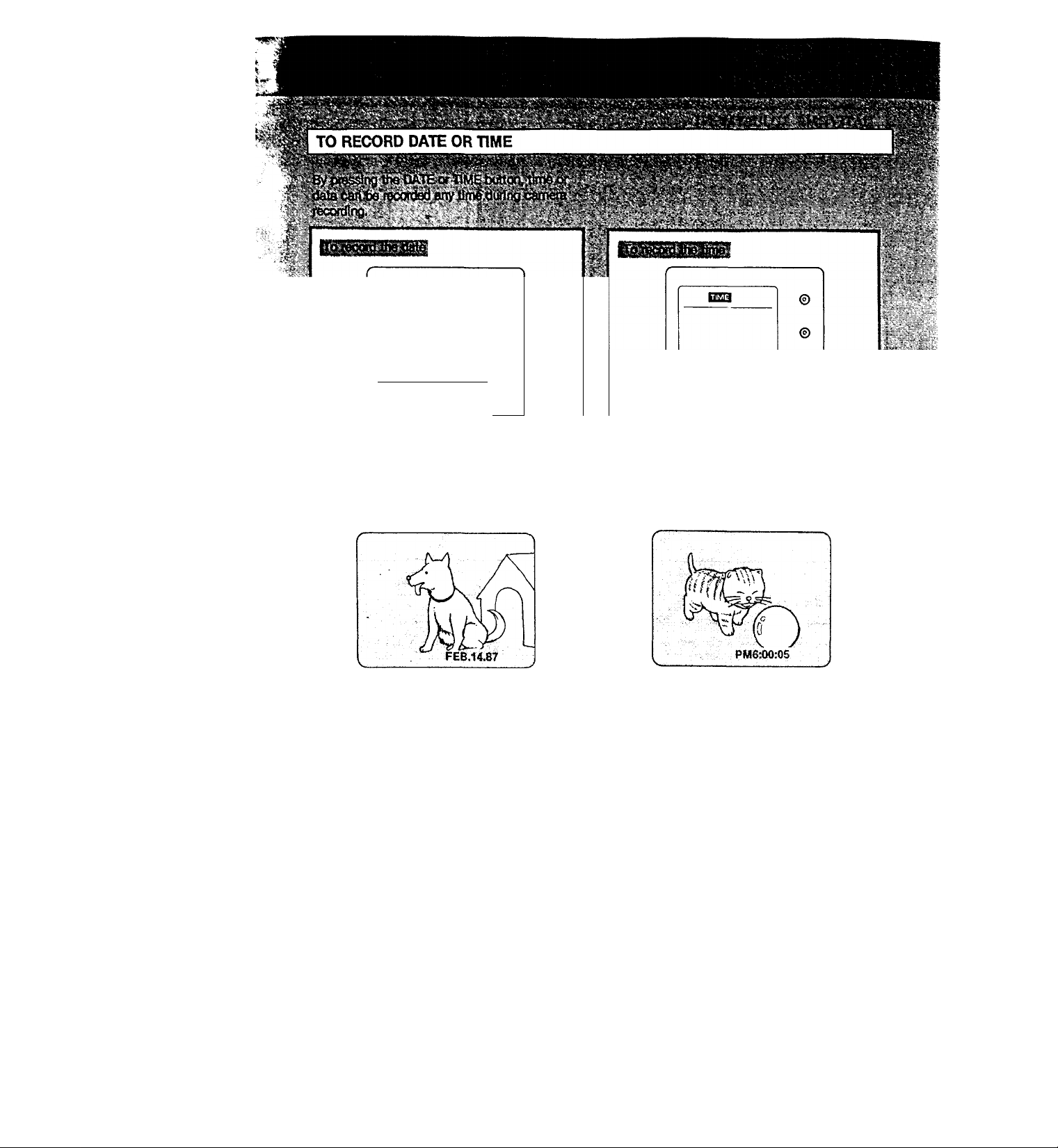
RECORDING DATE OR TIME
•■<- "••"•'■■ V' .-v.'-vr-'^‘,.\.''. -i ■„• o: ^ -,\->^ - • >.-•• •."• ^ ; '' \ k wX-X'^'-.-VX •.
*''v' k* .' S '••- k ; k'k.kk *_k-k . y . k ^.. k . k k V *k ,k ki k Î k*^k k> Xk'kkk:^ •* < ' Xj^kv*^ xxk^k X kkxV kkk'k k '■ V ' x';,-kN V * ' ' ^^^ -k kk'^.k k ' k"t ■•' • .>'V 'J
.J. 3^* “I *\V ' t X X V> -iSi. kX.xx'k V*J* ^ .■*»!». »»V (X ■*■ X X . X ^ ' .V.
3'‘ ‘ ''S k«<x.^V'* ‘ x"' *' '''‘'X'*'» 'X** * ' ^ ' V f> *t > '
. S s:.*i;»K?-:t-r ^ ,■" -< ^-X,Tv^'>-,V.-- -x .,---.^?'.:*r^- . ; - -v. *.'x '-k .: •?--kr- Xc-l r-s-^x^x:
^»k V ^ ^ i. ^ . \ *♦ .
'\**k.**'‘* X*' ' SV".x:':x'
'•-^'- X» stT.’yx - x-x
p
i %kV Hi^'»-iX-k't..x'l kx*«.\\'^'.H
X •■■^^“ vx vÎ4xO‘^‘^ *■* S,\»
k'y LITHIUM BATTERY INSERTION
Open the cover of the battery
1
compartment on the bottom of the
unît
Insert the supplied lithium battery
with the face marked + facing out
2
3 Close the coven
VÛthlumbatteiyfeplacement
« ;'¿^'both Ihe Indlcatofs DATE or TltvlE and <X)
. ■ ‘' battery by '^shifig ‘It .upward: i' 'vi V; k--
j , 3iT {Jofnial.op^ratioDi^^ife'o 0 jGtHluiTi battery
Notes on litlilum battery
• Keep it out of reach of children, Should it be
• Wipe it with a dry cloth to assure a good
• Be sure to observe the correct polarity when
• Do not hold it with metalic tweezers,
• Do not break it upnor throw itMo fire, which
"A-îiL'i: ■ .■■■'V‘r'4<=-■<? •* '. ■■''■ ■
?iir5" ¿sTTS-^V'- :-.-is:
swallowed, consult a doctor immediatelyk
contact.
installing it.
otherwises short-circuit may occur.
might cause it to exploda Carefully dispose of
the used batteries.
16 k
^yr. .
Page 17

Set the year.
The year changes:
86-87 99-»00-01
^—09-08
.............
Set the month.
Set the day.
Set the time.
Start the clock.
j:Hptps "" 'V ‘
DATA SET
JI _ inn
f'U I
DATA SET
DATA SET
Press at same time with the time signal. DATA SET
ESZ3
“I f il n
c- z\-Ç ‘
I
_ r -l.n n.nn
,1C -u u-u U
^ I N
S^[T^G
' I '
ADJUST
ADJUST
ADJUST
ADJUST
Bb^
I o n
I'U I
N 1 ^
T IL! ri n
C-7P-P '
V n.n n
—(;nO-Li Cl
¿¡n.fin
5-=5
u-nu
I '
SB3
. O n.n n
5--3
JU‘UU
" “ necessary to reset evert If thé battery pack of the
recorder is removed, as tonò as the lithium
battery is inserted.
blink by pressing DATA SET and correct It with
ADJUST.
• AM12.1D0 stands for midnight, and PW12:00 stands
for noon.
17
Page 18

©
©
.
PM
.nn.nr
6
■UU-U 3
PATH f~fiME HCOUNTE^
® @ @
The date in the display window
will be recorded as follows.
@
HME }c
The time in the display window
will be recorded as follows.
'iSj
18
To stop recording date or time
Press COUNTER. Camera recording will continue.
»Si
Page 19

me. or .counter
‘i'-jrtWliljecIlsplayed
VTR mode Indicator-
Camera mode Indicator-
-------------
--------------
LI U*U LhU LI
VTR
CAMSPLP
, function Is activated. ' *
~-~"Tape operation mode
_0 0-0 0-0 n
_Blinks when moisture has
condensed, (page 33)
.Blinks when the video heads
may have been contaminated.
Tape speed indicator—-
Blinks when the battery Is •
exhausted.
.......
.................................................‘ s
* Lights up when there is no
cassette inside.
Blinks when the tab on the
cassette is out or when the
tape is at its end,
....
19
Page 20

;,^e96ncnno'fiame^ra№-|^
/;- .. r. ‘ • ' ’ "'■ *'"■ '■* '■ "’*'■" ' ’*
CONNECTION
REMOTE
r -''T^ ix*K
20
* y ' ' *<• '' '
. ■* ' ' .' .' /4
Page 21

1 Fotlow steps 1 W»d 2 in opemiion Q].
2 To start recording, press the two # REC
' buttons at the same time.
A framoby-frame picture shooting is made (for 6
frames), and the recorder will.be set in the
recording pause mode automatically.
Repeat step 2 for continuous frame-by-frame
picture shooting.
i-ts
l?3Tost<^ recording momentaitly
£|l^ftess'lf.’c'.' '
To 8t<^ recording
Press».
•—-< «.-.....■«.■'...I.«. ..a..».
Toturnoffteepowar.-'l ri '
f^ess K)WERbfl .the Remote ' ,7^
(Or set the POWER switch to OFF.)
................................................ .»r .ifi I..»! ...J.i.y.i.i«i I... ..
21
Page 22

USE OF AN OPTIONAL MICROPHONE
i.' A ’'.X » .. . X ■ - V
X, ♦, ,^Xx^-*Ov ^ \SVV%?-Px‘^ 'r*'«
^ ' .'ir '' V ; •.*‘V'*'' "'.''■X';
■-. ^■ -r^.*; ^
?#^CAnACHMiNTOF^^
iMil
1 Attach the microphone to the
^
----------------------------------------------------
....
■'■ V V 5',^"■ X !*. ■ * * " -ix-
accessory shoe.
..........................
l/i
.Vi.'i'
Z :’'. '
/
X X,..^--^- ^
.
_^v ^
o
Mm Connect the microphone cabie
to the MIC Jack and the dc cable
to the MIC DC OUT Jack.
Power will be supplied to the
microphone.
M
X. TV
^ - -?T'
' X.
. % ^ / i
‘ lx,
xs
;•^Xi.VVir:*::VX■**'■.X>--r■': :: .■■-:■•
" '-■;T"X"T——>"T ‘r-'i —r <r"“'-:—‘
22
. 4^ .<V ^ , V l'
Page 23

^4 :
. ' "'i- 4'i '
1.,. V^tfhe switch to 3CH Of 4Ш, whlchev^ls'bot
’ adive in yotirarea.'
Select the same channel on the TV,
......................
- - -у.
Ч
^■%
■'<г
.
....
--------------------------------
■ * ^ ‘«V
j—’
„ . .^ < ''"хф»
ттгтгу.
*'
23
Page 24

— ............... '"••'¿^ri(.f
.5
. V /^|§ ?
^ " ' " K ^ ^ '*¿1
VIDEO OUT
AUDIO OUT J
RFU-88UC
VTRf f A
c
—s—
A ))
TV
N1
Antenna
selector
-V
t VHF input
VIDEO OUT
Connecting cord
AUDIO OUT VMC^MS/609MS AUDIO IN
(optionaO
TV set
About the Elector switch of tiw ontenna soiocfor * 2 coaxial cables are supplied to the RFU^UC.
.kw«0<li<?<hoRFO^Cy.i^^v;*^v'"v^^ ^ ^ .'.j.
To vlew a playback pictaie’of CCC-Vl ^ set to VTR.
To watch a TV program or the playback picture of
another VCa set to ANT;: i^ ^
24
0
Page 25

AUDIO IN
Connecting cord
VMC-608MS/609MS (optional)
Sv'y^À
25
Page 26

Press POWER.
Toirtop
Press STQP.
To rewind the tape
Press ■ <♦ 4 REW.
To advance the tape rapidly
Press ►► FF.
26
Notes
♦ The picture recorded In thè IP mode will not be,
equal to the picture recorded In SP mode In its
quality,
• If the Remote Commander ts disconnected during
playback, rewind, or fast forward, the mode will
be kept.
To stop the tape on the unit, set POWER to OFF.
Page 27

To view a freeze
picture.
- rV
-i i
«• '' Yx
To view a picture at a highspeed
II PAUSE
b
----------
---------------------
To view a stop-action
advance picture.
Press and release
!!► FRAME
f) - ^
\J
------
rv*5,
\
'
--------------------------------------
To view a slow-motion
picture
Keep pressing
ll> FRAME
_______________________
^ ' •"■< ■ 5' f
To go forward
©
CT
FF
\
To go back
Keep pressing
@
CD
REW
_
Keep pressing
T
To resume normal playback, press !► PLAY.
i^lfioteA A A"
Y" 'Streaks wifl appear and sound will be muted in the
freeze picture, Stopwaction advance picture, slow
motion picture and hlgtvspeed picture.
To resume normal playback,
release your finder.
27
Page 28

\i your VCFi does not have the input select switch,
make the eONNECTION fT) on page 25tn eddltlon
to the connection shown above.
28
Turn on the TV (or
VCR) and
select the
TV channel to
be recorded.
Page 29

Frame-by-frame recording of a TV program [.^' *
-1 Pfes8 POWER ion the ftsrnote'Commahd^ .
'2 Turn {w'theTv (or VC^ .and ielecl lhe'W! ‘ - \
channel to be recorded.
3 Press • REC (Ivw) buttons at <»nce) and ii
PAUSE simultaneously.
The recorder ts’seUn the re^rting^a^^ ,
'Prei'« Rs; %i^|:yoa
recording. ' " '
Repeat step 4 as many times as desired.-
’'i-.
Press • REC
3
(two buttons at once).
i «^op recording mbrnentartiy ‘
=*ress II. the pause mode will be airtomalicatiy
*- released after about 7 minutes and the recorder will
slop.
‘
To atop recording
Press
;>;< V« y, . ', .
V-v, Í, .
'. ‘„I."-.*/£..'S‘,Í<■ Î ii, “tiik,J,.,'aí Vi<V¿:ViiÍv-_. i ^ .
'i ... ''/X'VV*_ <V .' ~
recording, the recording continues.
To slop thé recording on the unit, set POWER to
OFF. ' '
29
Page 30

¿’Sit?
. if '
PosHkxi of the switch
COUNTER 0
COUNTER [JJ
Counter indication
0^0:00
0000
When to use
• During playback of a tape recorded in the SP mode.
• During recording
• During playback of a tape recorded In the LP mode
• During playback of a tape recorded in the SP and LP modes
• During recording
.5ER*|»l*iSar«M«F5gSf4S if:
TAPE RETURN
---
----------
----
—T-,
PP=
Example of using the (WX):00 counter
.............................................
1 1 1 1
( ^ ^
...............................
'"-u ^
©
1 ®
isliftfSssK
■;— ----------—
'Displi^y wlnSow
•MEMORY button
RESET button
-------
The tape will be rewound to the point where BESET has been pressed.
But there may be time lag of up to 6 digits. . , > ,
Notes . ^
• TheCfcOOiJOboohtermaybeusedasalime ' counter. ' • >
1 digit corresponds to approximately 1 second.
• The OiOO.'OO counter wilt not operate when a blank
section of a tape or a tape recorded in the LR
mode is played back.
■ The counter reading will be retained in the
memoty as long as the litWuth battery -fs not
exhausted or removed.
When Inserting a new tape, make sure that you
press RESET and reset the counter to 0;00;00 or
0000.
30
¡■I
—i—r-
1»
*1
Page 31

cTO «ECORO THE PLAYBACK OF ANOTHER VCR
AV IN
your VCR Is a stereo type, ¡use Jhe VMC-
3/609f^ connecting cord.
i.AtMut the EDIT switch (inside the bottom panel)
When editing a tape, slide the switch In the direction
?of the narrow.
f >v'*
Connecting cord (supplied)
The quality of the edited tape will be improved. But j; ;
avoid repetiUon of editing tapes.'ifis^epiciure iuid, /''
tone quaflty will be impaired noticeably to newiy '
edited tapes. , ' ^ .
After you have finished editing tapes, reset the
position of the switch. ^ -
AUDIO OUT
m
31
Page 32

When Ihe CCD^I ^ |h6 VCR fo’lee^ng
CONTROL SIN
-r
i
'T REMOTE
"►EOD^
Qj
,
.......
i
^ V . Gi
.............
........
................
*-0ZEt=>
I ' J; ’’ ‘Ki ¿,7
’If»
. .,..........^
......
-ir.r .■,.... . ■ '. . ..
Wbertihe COUNT 1/i iael«CtC8‘Js'^U0 Count i,' ^
there may be time tag of up io iO digits during
assemble editing of 8 programs using the RM-
ElOOV.
To edit a tape recorded (n the SP and tP modes,
set the COUNT 1/2 selector to COUNT 2-
32
■ POWER
O C3
'S.
CONTROL L
------
ccUlLJii “*■
REMOTE Connecting cord suppiied to
RM-E100V _
(5-pin -* 5-pin) CONTROL L |
Video editing controiler
RM-E100V
_______
(=3
crrj oa 1
= C=9C_.
>S
--------------------------II rj|
1
LJI
CD
•"*1 *tt ** ** j
Page 33

MOISTURE INSIDE THE VIDEO CAMERA
RECODER
tf this unit Is brought directly from a cold to a warm location,
moisture may condense on the drum assembly Inside the unit. In
this condition, the tape may adhere to the head^drum.
To prevent possible damage under these circumstances, the
recorder is furnished with a moisture sensor.
If moisture is present, the (Urnarfr will blink and the function
buttons except for the EJECT button will not function. When a
cassette has been Inserted, the [i] mark and the EJECT lamp will
blink and the tape will be automatically unloaded (but the tape
will not be ejected).
MOISTURE ON THE TAPE
If a tape is brought directly from a
cold to a warm location, moisture
may condense on the warm
location, moisture may condense on
the surface of the tape. When the
tape is Inserted and a tape transport
button such as ► Is pressed, the
EJECT lamp will blink and the
function buttons except for the
EJECT button will not function.
If the EJECT lamp blinks When to use
Press ± EJECT and remove the tape for about one hour.
There may be other causes than moisture condensation, contact your Sony dealer or
local Sony service facility.
The unit can be used again if the EJECT
iamp does not light when a cassette is
inserted and a tape transport button is
pressed.
If the lamp keeps on blinking
33
Page 34

‘S, S
Operate the unit on 6-85V dc.
For dc or ac operation, use the accessories
recommended in this manuai.
Shouid any solid object or liquid fall into the
cabinet, unplug tt?e unit and have it checked
by qualified personnel before operating it any
further.
Avoid rough handling or mechanical shock to
the unit. Be particularly careful of the lens.
Avoid shooting the same object for a long
period of time, (for example, as a lookout
camera), as this will damage the color filter
inside the camera
Remove and store video cassettes after
recording or playback.
Do not wrap up the unit and operate it
because heat may build up internally.
Avoid using and storing the recorder in the
following locations.
—Locations susceptible to vibration.
—Locations exposed to strong magnetic
fields.
—Locations near TV or radio transmitters
where strong radio waves are generated.
. '■ t O t .X » r'x-:- \ s r'N *>1 f'N »X. r'-
V - V 1 ^ \ 1 X ' V 1 A ; J »s *
Each country has special TV color broadcast
and electricity systems. Before using your
recorder abroad, check the following points.
Differences in color systems
If you prepare fully charged batteries and extra
video cassette tapes, you can use your recorder
in any country. However, to monitor the playback
picture on a TV, the TV must be based on the
NTSC system and have the video/audio inputs.
NTSC system countries
Bahama Islands, Canada, Central America,
Japan, Korea, Mexico, Taiwan, the Phillipines,
U.SA, etc.
PAL system countries
Australia, Austria, Belgium, China, Denmark,
Great Britain, Holland, Hong Kong, Italy,
Kuwait, New Zealand, Norway, Portugal,
Singapore, Spain, Sweden, Switzerland,
Thailand, West Germany, etc.
SECAM system countries
Bulgaria, France, Hungary, Iran, Iraq,
Luxemburg, Monaco, Poland, the Soviet
Union, etc.
CARE
• Store cassettes in their cases and keep them
in an upright position to prevent intrusion of
dust and uneven winding.
• When the unit will not be used for a long
period of time, periodically turn on the power,
operate the camera section and recorder
section and play back a tape for about three
minutes.-
• Clean the lens with a soft brush to remove
dust. If there are fingerprints on the lens,
remove them with a soft cloth. Clean the
recorder body with a dry, soft cloth, or a soft
cloth lightly moistened with a mild detergent
solution. Do not use any type of solvent which
may damage the finish.
For protection, keep the lens cap on the lens
when not using the camera.
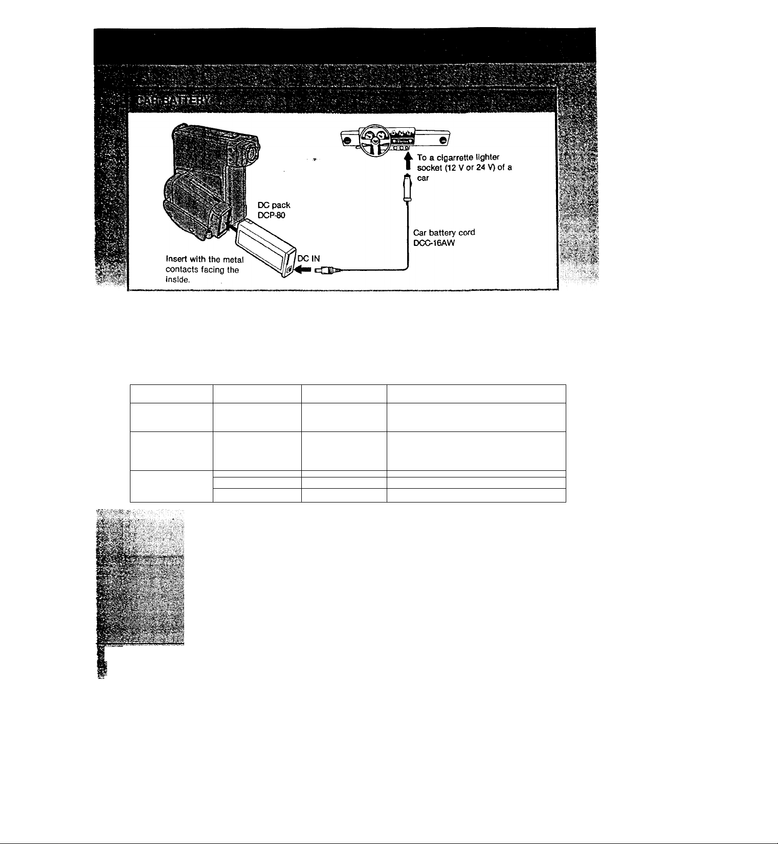
To charge the battery
Prepare a Sony BCA-70 battery charge adaptor,
DCP-80 dc pack and a DCC-16AW car battery
cord. The battery can be charged with a 12 V or
24 V car battery.
For details on charging, please read the
instruction manual furnished with each unit.
34
Page 35

eì iS ft-; aVì; I c)S IC: .
System
VWeo tBconding system
Rotary two heads,
Audio recording system
Video signal NTSC color, BA standards
Usable cassette 8mm video format cassette
Tape speed SP; Approx. 1.43 cm/sec.
Recording or playback time
Fast forward time Approx. 3 min. (P6-60)
Image device CCD (Charge Coupled Device)
Viewfinder
Lens
Depth of field *
focus
mark
point
1.5
•
M
(4.9) (3.9-6.6)
2.4
u
(7.9)
6,0
à
(19.7)
Helical scanning FM system
Rotary head, FM system
IP: Approx. 0.72 cnVsec.
(playback only)
120 min, (P6-120)
OVF
f=15 mm, F1.6
3 positions zone focus
m (feet)
indoors
1.2-2.0
1.7-42
(5.6-13.8) (3.9-“) (2.6-00)
2.9-^
(9.5-“)
Cloudy
day
0.9-45
(3.0-14.8)
1.2-“
1.7-“
(5.6-^)
sunny
day
0.6-°o
(2.0-0°)
0,8-00
1.0-0°
(3.3-0°)
Data Display System
Clock
Date Irxlication
Time Indication
Power back-up
General
Power requirements
Power consumption
Installation
Operating temperature
Storage temperature
Dimensions
131.5
Crystal lock
From Jaa 1,1986 to Dea 31,
2009
12-hour cycle
Back-up duration of 2 years
wtth lithium battery CR2025
Battery compartment 6 V/85 V
6 W (camera recording)
VertiCcilly
0*C to 40'C (32°F to 104°F)
-20“C to + 60”C (-4"F to
-H40-F)
Approx. 1315 X 185.5 X 206 mm
(w/h/d)
(5'/4 X 7% X inches)
206
Colour temperature -.if : 3200 K
Minimum illumination
Illumination range 17—100,000 lux
Recommended illumination
Input and output jacks
Video input
Audio input
Video output
Audio output
RFU DCOUT
Earphone
REMOTE
MIC
MIC DC OUT
: 5800 K
17 lux (15 footcandles)
(15—9294 footcandles)
More than 300 lux
(28 footcandles)
Miniphono jack
1 Vp-p, 75 ohms unbalanced,
sync negative
Miniphono jack
-10 dBs, input impedance more
than 47.kilohms
Phono jack
1 Vp-p, 75 ohms unbalanced,
sync negative
Phono jack
-10 dBs, output impedance
less than 2.2 kilohms
Special minijack,
5V DC, for the RFU58UC only
Minijack 8-ohm impedance
Spin connector
Minijack -66 dBs, low
impedance
with 25V-3V DC output,
impedance 6,8 kilohms
Sepcial minijack
5V DC
Weight
Microphone
Remote Commander RM-87
Dimensions
Weight
Cable length
Accessories supplied
Optional accessories
Battery pack NP-22, NP4000, DC pack DCP-80, Car
battery cord DCC-16AW, External rnicrophone shoe
SAD-100
Design and specifications subject to change without
notice.
Approx. 15 kg (2 lb 14 oz.)
excluding the battery and
cassette
Approx. 1.6 kg (3 lb 8 oz.)
including the battery and
cassette
Electret condenser
microphone, omni-directional
monaural type
Approx. 50 X 125 X 17 mm
(w/h/d)
(2 X 5 X :V4 inches)
Approx. 87 g (3 oz) including the
cable
/^prox. 1.5 m (4.9 feet inches)
Connecting cord (1)
Shoulder strap (1)
Remote Commander RM-87 (1)
Lithium battery (1)
35
Page 36

il
If you think you have a problem, double-check before calling the serviceman. You may have overiooked something relatively simple!
Symptom
<J6es hot ofwrate. ^
Recording cannot be done
even when the • REC
buttons are pressed.
The power turns off.
A vertical band appears
when a subject such as
lights or a candle flame is
shot against a dark
background.
The battery pack Is quickly
discharged.
The cassette cannot be
removed from the
compartment.
The playback picture is not
clear.
The picture is noisy.
Playback cannot be done
even when the ► button is
pressed.
Cause
Procedure
;1Tie tap© te iifftk^ci fo It» dfbm. .Berfio^'GiPc^^'tte viflth
bOtton.‘
The tape fe at Its «td.
Rewind th6.tapet)r use a new one. -
The recorder is eel to the VTR mode. STANDBY.
the Remote "Commander has been
Set POWER to OFF and ON again.
disconnected Ttoina operation.
The tab on the cassette Is out (red).
The tape is at Its end.
The recorder has been In the camera
recording pause mode for more than 7
minutes.
The battery is exhausted.
The contrast between the subject and
background is too high; the camera is
not malfunctioning.
The ambient temperature is too low.
The battery pack has not been
charged fully.
The battery is exhausted.
EDIT switch is set to the "
position.
The recording was made out of focus.
The video heads may be
contaminated.
The tape is at its end.
Use a new cassette or slide the tab
in.
Rewind the tape or use a new one.
Turn pn the power again.
Use a charged battery.
Charge the battery pack again.
Use the charged battery.
Set the EDIT switch to the normal
position.
Clean the heads using a cleaning
cassette.
Rewind the tape.
if the trouble is not among the above list, look at the indicators and check the symptoms.
36
Page 37

To make sure you don't miss those “once In a
lifetime” scenes, go over the foUowing check list
and make the necessary preparations.
Required for recoctling
CCD-V1 Is the shoulder strap
attached?
Battery pack N P-22
Cassette tapes
Convenient accessories
Tripod Required for scenes in
Is It charged?
Are there enough battery
packs to cover the
planned recording time?
Have you prepared enough
tapes to cover the planned
recording time?
which stability of the
camera is important.
Tripod mount screw must
match the receptacle
mount.
AC pack ACP-80UC Can be used to operate the
video camera recorder on
house current and to
charge batteries with the
BCA-70 battery charge
adaptor.
Battery charge adaptor BCA-70
Used to charge battery
packs.
RFU adaptor RFi>88UC
Adaptor with & VHP OUT
terminai for easy
connection to a
conventionai TV
External spot microphone
Back eiectret condenser
microphone which records
the specific sound source
being aimed at
External microphone shoe SAD-100
Attaches microphone
directly to the unit for
trouble-free recording.
Video light Required for recording in
low light situations.
Earphone (miniplug) Permits monitoring of audio
signal during recording.
37
Page 38

? n tv •
Shoot with the sun at your back (frontlighting).
For staible shooting, hoid the upper arm firmly
against the body.
Make each scene &-7 seconds in length for
easier viewing.
Mainly, use medium and close-up shots.
Light the subject sufficiently.
Vary the angla
'■ V" 'fc
'
»'• • !b-; 5.\; V V
1 ^ ■ 1 ' '
; t: 1',
ORGANIZATION
— Is the key
Befor shooting, think about how one scene will
lead into another scene. This will help you to
create a programme that has a sense of
progressioa
SCENE LENGETH
—not too long, not too short
While there’s rto hard-and-fast aile, it is generally
advisable to make each scene 6-7 seconds in
length for easier viewing. A successkxi of short
scenes can tire the viewer, while a very long
scene can become tx>rina.
38
Page 39

FRAMING PEOPLE
BRIGHTNESS LEVELS
Basic shots for properly framing people are as
follows.
[ a ] Bust shot—Chest and above
[ b ] Waist shot—Upper hips and above
[ c ] Knee shot—Knees and above
[ d ] Full shot—Entire body
lai Ibl
■ Ч .
_______
/
V
[dl
Л>
i
_______
The single greatest Influence on picture quality
is the brightness level. Using the following chart
as a reference, take a few minutes to familiarize
yourself with brightness levels to improve your
recording.
(formai tOjK»
recording
Video light
recommended
Video light
required
j
, Unitkix- Snow4»yefed meurttaifts
lOOjMO Ctearday, «WWay (100,000)
Snow fields
Sandy beacH, clear day in Summer
Clear day, midaflemoon ^,000)
Overcast d^. «ЧсМау <32fl00)
Overcast day. one hour
after euerisfi (2,000)
Office Ш by fluorescent
lamps, n ear window (1,0001
1,000
Ciearday, one hour txj'ore
sunset (1.000)
Departm ent store counter (5(X) — 700)
Station wicket (650)
500
Office lit by fluorescent lamps
(400 - 500)
Room lit by two 30 W
fluorescent lamps (300)
Subway station platform (300)
Arcade at night (150—200)
100
Theater lobby (15—35)
Candle light (10—15)
10
CAMERA POSITfON AND ANGLE
Camera position and angle Screen effect
Basic angle
Low angle
High angle
The camera person stands,
keeping the camera at eye
level with the subject.
This angle is used when
the subject is higher than
eye level.
This angle is used for
subjects below eye level.
• This angle provides the most stable
appearance on the screen and should be used
as much as possible.
• People appear taller from this angle and the
impression is given that they are domineering
and overpowering.
• In a thriller type production, feelings of terror
or anxiety can be created.
• Used to shoot large numbers of people,
flowers, etc., so each can be seen.
• Can be used to emphasize feelings of
smallness and distance.
39
Page 40

The following units are packed with the
CCD-V1 video camera recorder.
Battery pack N P-22, AC pack/battery
charger ACP-80UC, Battery charge
adaptor BCA-70, RFU adaptor RFU-88UC
For details on these units, please read
their Instructlontnanuals.
Sony Corporation Printed in Japan
3-765-512-21 (1)
 Loading...