

Page 1

4-452-968-01 (1)
HD Camera Adaptor
Operating Instructions
Before operating the unit, please read this manual thoroughly
and retain it for future reference.
CA-TX70
© 2012 Sony Corporation
Page 2

WARNING
To reduce the risk of fire or
electric shock, do not expose
this apparatus to rain or
moisture.
This device complies with Part 15 of the
FCC Rules. Operation is subject to the
following two conditions: (1) this device
may not cause harmful interference,
and (2) this device must accept any
interference received, including
interference that may cause undesired
operation.
To avoid electrical shock, do
not open the cabinet. Refer
servicing to qualified
personnel only.
IMPORTANT
The nameplate is located on the
bottom.
For the customers in the U.S.A.
This equipment has been tested and
found to comply with the limits for a
Class A digital device, pursuant to Part
15 of the FCC Rules. These limits are
designed to provide reasonable
protection against harmful interference
when the equipment is operated in a
commercial environment. This
equipment generates, uses, and can
radiate radio frequency energy and, if
not installed and used in accordance
with the instruction manual, may cause
harmful interference to radio
communications. Operation of this
equipment in a residential area is likely
to cause harmful interference in which
case the user will be required to correct
the interference at his own expense.
You are cautioned that any changes or
modifications not expressly approved in
this manual could void your authority to
operate this equipment.
All interface cables used to connect
peripherals must be shielded in order to
comply with the limits for a digital device
pursuant to Subpart B of Part 15 of FCC
Rules.
For the customers in Canada
This Class A digital apparatus complies
with Canadian ICES-003.
For the customers in Europe
This product with the CE marking
complies with the EMC Directive issued
by the Commission of the European
Community.
Compliance with this directive implies
conformity to the following European
standards:
• EN55103-1: Electromagnetic
Interference (Emission)
• EN55103-2: Electromagnetic
Susceptibility (Immunity)
This product is intended for use in the
following Electromagnetic
Environments: E1 (residential), E2
(commercial and light industrial), E3
(urban outdoors), E4 (controlled EMC
environment, ex. TV studio).
For the customers in Europe
This product has been manufactured by
or on behalf of Sony Corporation, 1-7-1
Konan Minato-ku Tokyo, 108-0075
Japan. Inquiries related to product
compliance based on European Union
legislation shall be addressed to the
authorized representative, Sony
Deutschland GmbH, Hedelfinger
Strasse 61, 70327 Stuttgart, Germany.
For any service or guarantee matters,
please refer to the addresses provided
in the separate service or guarantee
documents.
2
Page 3

Table of Contents
Overview ....................................................................... 4
Features ........................................................................ 4
Names and Functions of Parts ................................... 5
System Configuration .................................................. 9
Preparation and Setting ............................................. 10
Attaching the Adaptor to a Camera/Camcorder ...... 10
Connecting a Camera Control Unit (CCU) .............. 11
Attaching the Accessory Shoe Kit ........................... 12
Outputting Trunk Signal .......................................... 13
Using an Intercom ................................................... 13
Starting the System ................................................. 14
Setting the System Format ..................................... 14
Error Messages ....................................................... 16
Important Notes on Operation .................................. 17
Specifications ............................................................. 19
General ................................................................... 19
Connectors .............................................................. 19
Supplied Accessories .............................................. 19
Other peripheral devices ......................................... 19
Pin assignment ....................................................... 20
Table of Contents
3
Page 4

Overview
Features
The CA-TX70 HD Camera Adaptor is a
camera adaptor that allows for long
distance transmission of input and
output signals via a triax cable, and
power supply to the connected camera
or camcorder. Combined with the
HXCU-100 HD Camera Control Unit
(CCU), the adaptor allows you live
broadcast operation.
Can be installed on the following
camera/camcorder
• HXC-D70 series
• PMW-500 series
• PMW-350 series
• PMW-320 series
1) An optional CBK-HD02 SDI/
COMPOSITE Input and 50 Pin Interface
is required.
2) An optional CBK-CE01 50 Pin Interface
and Digital Extender is required.
1)
2)
2)
Cable-free connection to camera/
camcorder
The adaptor can be installed on the
attachment shoe of a camera/
camcorder, allowing for connection of
input and output signals or power
supplies via the 50 pin interface and
BATT interface. As no cables are
necessary for attachment, the adaptor
offers a solution for solid camerasystem configuration.
Digital triax transmission
The CCU and camera are connected
using the industry-standard doubleshielded triaxial camera cable
(commonly referred to as triax). The
latest Sony-developed digital
transmission technology, which is
incorporated in the adaptor and CCU,
transmits high-resolution pictures
between the adaptor and CCU,
regardless of the cable length.
Support for live camera system
operation
The adaptor is equipped with the
following features and input/output
connectors to allow for live
broadcasting, not only with the HXCD70 but with standalone camcorders.
• Intercom feature (2 switchable lines;
engineer or producer line)
• Tally lamp (red and green)
• Call feature
• Return signal feature (up to
selectable 4 lines)
• Prompter output
Overview / Features
4
Page 5
Names and Functions of Parts
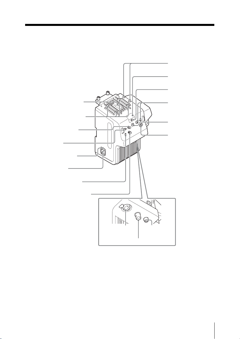
Front
qf Accessory screw holes
qd Screw holes for V-wedge
shoe attachment of HD
viewfinder
qs PGM volume control
qa MIC switch
0 POWER lamp (red)/
(green)
9 POWER switch
8 INTERCOM line switch
7 INTERCOM volume control
qg INTERCOM
connector
qh PROMPTER connector
1 Cable clamp
attachment
2 TALLY lamp
(red)/(green)
3 TALLY switch
4 RET button /
RET 2/3/4 switch
5 RET 1 button
6 CALL button
qj RET CTRL
connector
Names and Functions of Parts
5
Page 6
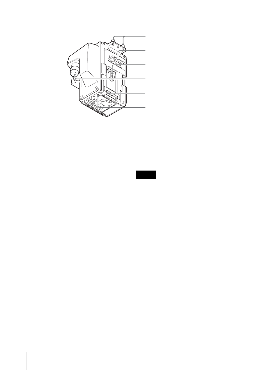
Rear
qk Camera/
Camcorder screws
ql Camera/Camcorder
connector
w; V shoe
wa CCU connector
ws Camera/
Camcorder power
supply connector
wd Screw hole for
camera/camcorder
a Cable clamp attachment
Attaches the supplied cable clamp belt.
b TALLY lamp (red)/(green)
When the TALLY switch is set to ON,
the TALLY lamp lights to indicate that a
tally signal is input to the connected
camera control unit or a call signal is
generated by pressing the CALL button.
When the TALLY switch is set to OFF,
the lamp does not light.
c TALLY switch
Set to ON when you use the TALLY
lamp.
d RET button / RET 2/3/4 switch
When using return video 1 and other
line simultaneously, the return video
signal selected with the RET 2/3/4
switch is displayed on the viewfinder
screen while the RET button is pressed.
e RET 1 button
The return video 1 signal from the
camera control unit is monitored on the
viewfinder screen while this button is
pressed.
Notes
• If you press both the RET 1 button
and RET button (RET 2/3/4), the RET
1 button takes priority.
• When the adaptor is connected to the
PMW-500/350/320 Solid-State
Memory Camcorder, if you change
the return video signal, the previously
selected return signal may be
displayed for a moment in the
viewfinder.
• When the adaptor is connected to the
PMW-500/350/320 Solid-State
Memory Camcorder, if you press the
RET button to switch the displayed
picture, the picture in the viewfinder
may be distorted for a moment. This
is not a malfunction.
f CALL button
When this button is pressed, the red
CALL lamp on the front panel of a CCU
or external controlling device (RCP/RM,
etc.) will light.
Names and Functions of Parts
6
Page 7

g INTERCOM volume control
Adjusts the volume level of the headset
connected to the INTERCOM
connector.
h INTERCOM line switch
Selects the talk line.
PROD: To talk over the producer line.
ENG: To talk over the engineer line.
Note
When the adaptor is connected to the
HXC-D70 HD Color Camera, the
intercom of HXC-D70 becomes
available. In this case, you can select
the intercom line (PROD/ENG) of HXCD70 by the INTERCOM line switch of
the adaptor.
i POWER switch
Set to ON to turn on the adaptor and set
to STBY to turn it off. When the adaptor
is set to STBY, power will not be
supplied to the connected camera/
camcorder.
j POWER lamp (red)/(green)
When the adaptor is turned on, the
POWER lamp lights in green. If the
POWER switch is set to STBY when the
CCU is turned on, the POWER lamp
lights in red.
k MIC (intercom mic) switch
Turns on or off output of intercom audio
signals. Set to ON when you talk to a
CCU or external system.
l PGM (program) volume control
Adjusts the audio listening level of
program 1.
m Screw holes for V-wedge shoe
attachment of HD viewfinder
These are V-wedge shoe attachment
for HD viewfinder screw holes (4) for
M4 screws to secure an HD monitor.
n Accessory screw holes
These comprise of a U1/4”-20 screw
hole to secure an accessory, four screw
holes to secure the supplied accessory
fitting shoe (for the DXF-C50WA
Electronic Viewfinder), and four screw
holes to secure the optional cold shoe
kit (X-2546-633-).
o INTERCOM connector (XLR 5-
pin)
Used for input and output of intercom
audio signals if an XLR 5-pin headset is
connected.
For information on pin assignment, see
“INTERCOM” in “Pin assignment” on page 20.
p PROMPTER connector (BNC)
For output of the VBS prompter signal
when a CCU is connected.
q RET CTRL (return control)
connector (6-pin)
Connects the CAC-6 Return Video
Selector.
For information on pin assignment, see “RET
CTRL” in “Pin assignment” on page 20.
Pin No.1 (INCOM MIC-ON/OFF) turns on or off
the microphone of intercom headset that is
connected to the adaptor.
When the adaptor is connected to the HXCD70, you cannot control the intercom headset
that is connected to the HXC-D70.
r Camera/Camcorder screws
Screws to secure the adaptor to the
camera/camcorder.
Names and Functions of Parts
7
Page 8

s Camera/Camcorder connector
(50-pin)
Connect to the adaptor connector of the
camera or the camera adaptor
connector of the camcorder (requires
installation of an optional interface) to
send and receive video and audio
signals.
t V shoe
This is a V shoe for attachment of this
adaptor to a camera/camcorder.
u CCU connector (triax connector)
Connects the adaptor and HXCU-100
HD Camera Control Unit using a triax
cable.
v Camera/Camcorder power
supply connector
Supplies power to the camera/
camcorder.
w Screw hole for camera/
camcorder
A screw hole to fix the camera or
camcorder. Use the screws for CA
bracket.
Names and Functions of Parts
8
Page 9

System Configuration
Examples of devices and parts that may
be used with the CA-TX70 are shown
below.
Intercom Headset
CAC-6 Return Video Selector
HXC-D70
HD Color Camera
Triax Cable
CA-TX70 HD
Camera
1)
/3502)/320
Adaptor
2)
Prompter
Video Output
or
PMW-500
Solid-State Memory
Camcorder
For details on usage of the adaptor when
connected to the HXCU-100 HD Camera
Control Unit, refer to the operation instructions
of the HXCU-100.
Return Video Input
Sync Input
HXCU-100 HD
Camera Control Unit
(Attaches to the front
panel of the HXCU-100)
HKCU-FP1 CCU
Control Panel
Prompter
Video Input
CCA-5 Cable/
LAN Cable
Picture Monitor
HD SDI/SD
SDI/VBS
Video
Outputs
AC Power
Intercom Headset
RCP-1000-series
Remote Control Panel
1)
An optional CBK-HD02 SDI/COMPOSITE Input and 50 Pin Interface is required.
2)
An optional CBK-CE01 50 Pin Interface and Digital Extender is required.
System Configuration
9
Page 10

Preparation and Setting
Attaching the Adaptor to a Camera/Camcorder
1 Loosen the screws on the 50P
cover of the camera or camcorder,
then remove it.
2 Fix the supplied CA bracket on the
battery attachment shoe of the
camera or camcorder using the two
screws (+K2.6×5).
50P cover
Attachment screws
Attachment screws
Note
Tighten the screws securely so that the
unit will not fall off.
CA bracket
3 Slide down the adaptor from the
upper side of the battery
attachment shoe of the camera/
camcorder.
4 Tighten the attachment screws at
the top (2) and lower part (1) of the
adaptor.
Preparation and Setting
10
To re mov e
Perform the installation procedure in
reverse, loosening the screws that were
tightened then.
Page 11

Connecting a Camera Control Unit (CCU)
When operating the camera in a system
with a CCU, connect between the CCU
connector of the adaptor and the
CAMERA connector of the CCU.
When required, secure the cable to the
adaptor, using the supplied cable clamp
belt.
To use the cable clamp belt
1 Insert the belt bracket C into hole
A or B of the cable clamp belt.
2 Secure the belt to the Cable clamp
attachment using the two supplied
screws (+B3×8).
3 1 Release the buckle, 2 bundle
the cable with the belt, 3 then lock
the buckle again.
1
3
2
4 Adjust the length by pulling down
the end of the belt.
Preparation and Setting
11
Page 12

Attaching the Accessory Shoe Kit
When you attach the DXF-51 or DXFC50WA Electronic Viewfinder, screw
the supplied accessory shoe kit to the
accessory shoe holes of the adaptor
(four holes), then attach the viewfinder
to the accessory shoe.
To attach the accessory shoe
Screw (+K3×6)
Accessory
shoe
Stopper
Plate
spring
1 Attach the accessory shoe using
the four screws supplied with the
shoe kit (+K3×6).
2 Slide the plate spring in the
direction shown by the arrow and
secure the spring using the
stopper.
Preparation and Setting
12
Page 13

Outputting Trunk Signal
When connected to the HXC-D70 HD Color Camera
You can communicate with an external device that is connected to the TRUNK
connector (RS-232C) or REMOTE connector of the HXC-D70, and an external
device that is connected to the TRUNK connector of the CCU.
To output trunk signal from the HXC-D70
Configure the following menu (MAINTENANCE menu M14: <TRUNK>) of the HXCD70.
Configure IF (interface) according to the connected device.
Menu page Item Setting Description
<TRUNK> TRUNK OFF Disable the trunk signal output
ON* Enable the trunk signal output
IF 232c* Outputs from the TRUNK connector
via RS-232C I/F
422a Outputs from the REMOTE connector
via RS-422A I/F
* default setting.
Using an Intercom
You can talk to the CCU operator by attaching an intercom headset to the
INTERCOM connector of the adaptor.
When connected to the HXC-D70 HD Color Camera
The INTERCOM connector of the HXC-D70 is also available for communication with
the CCU operator. The talk line of the HXC-D70 can be controlled by the INTERCOM
line switch of the adaptor.
• Configure the settings of the connected intercom headset in the OPERATION
menu of the HXC-D70.
13 <HEAD SET>: Settings for input of the headset’s microphone
14 <INTERCOM LEVEL>: Settings for the SIDE TONE level of the headset
The displayed items in the above menu are as follows:
INTERCOM1 (CAM): Intercom settings of the HXC-D70
INTERCOM2 (CA): Intercom settings of the adaptor
For details of the setting items, refer to the operating instructions of the HXC-D70.
When you do not use the INTERCOM connector of the HXC-D70, set the
INTERCOM ON/OFF switch of the HXC-D70 to OFF.
• The adaptor can control one PGM (program audio) system.
An audio signal that is input to the PGM1 of CCU is transmitted.
Preparation and Setting
13
Page 14

Note
When the PMW-500/350/320 Solid-State Memory Camcorder is connected, the
microphone input settings for the intercom headset will be fixed at the following
(factory default) values:
Dynamic / -60dB / Unbalanced
For information on connection to an intercom system and configuration of the
settings, contact your Sony dealer.
Starting the System
1 Attach the adaptor to the camera/camcorder, then connect the adaptor to the CCU
using a triax cable.
2 Set the POWER switch of the adaptor and camera/camcorder to ON, then set the
POWER switch of the CCU to ON. Power will be supplied to the adaptor from the
CCU and the adaptor turns on. The adaptor then supplies power to the camera/
camcorder, which turns on.
While the system is starting up, the POWER lamp (green) blinks at 0.5 Hz. When the
communication for certification between the adaptor and camera/camcorder
completes, the POWER lamp (green) lights.
Note
When the POWER switch of the connected camera/camcorder is set to OFF, or when
the camera/camcorder does not start normally, the POWER lamp (green) keeps
blinking at 0.5 Hz.
Setting the System Format
To record/output with the system, it is necessary to set the video format for the
camera/camcorder, adaptor and CCU.
The adaptor supports the following video formats.
• 1920×1080/59.94i
• 1280×720/59.94P
• 1920×1080/50i
• 1280×720/50P
The video format setting of the adaptor is synchronized with that of the CCU.
Preparation and Setting
14
Page 15

1 When connected to the HXC-D70 HD Color Camera
Both the video format setting of the adaptor and HXC-D70 are synchronized with that
of the CCU (HXCU-100).
2 When connected to the PMW-500/350/320 Solid-State
Memory Camcorder
As PMW-500/350/320 supports video formats that the adaptor and CCU do not, the
video format setting of the camcorder is not synchronized with those of the CCU. Set
the video format of the camcorder according to the video format setting of the CCU.
The video format can be confirmed in the viewfinder.
If video formats (recording format or system frequency) are inconsistent between the
adaptor and camcorder, the POWER lamp (green) of the adaptor blinks at 2 Hz. For
details, see “Error Messages” on page 16.
Note
As the adaptor supports bidirectional transmission of HD digital signals, the adaptor
will not operate properly if the camcorder is in the SD mode. Also, when an
unsupported video format for the adaptor and CCU is selected or the SDI OUTPUT
setting is set to SD in the camcorder, the adaptor will not operate. For information on
the mode setting of the camcorder, refer to the operating instructions of the
camcorder.
Preparation and Setting
15
Page 16

Error Messages
When an error is detected, an error message shown in the below table appears.
Since the adaptor does not have a display, the message is displayed in the menu of
the CCU or the remote control panel. The adaptor also alarms it by blinking the
POWER lamp (green).
POWER
lamp (Green)
Blinks (2 Hz) - - The video formats
Blinks (2 Hz) CHU: PS (CA)
Blinks (4 Hz) CHU: PS (CA)
Blinks (4 Hz) CHU: PS (CA)
Display in the
remote control
panel
Care
(Temperature)
Warning
(Temperature)
Warning (Fan)
Display in the CCU Indication
(recording format or system
frequency) are inconsistent
between the adaptor/CCU
and the camera/camcorder
CAM: PS (CA) CARE Internal temperature is
high
CAM: PS (CA)
WARNING
CAM: PS (CA)
WARNING
Internal temperature is
abnormally high
The internal fan does not
rotate
Preparation and Setting
16
Page 17

Important Notes on Operation
Use and storage locations
Store in a level, ventilated place. Avoid
using or storing the adaptor in the
following places.
• In excessive heat or cold. Operating
temperature range is –10°C to + 45°C
(14°F to 113°F). When connected to
the camcorder, the operating
temperature range is 0°C to 40°C
(32°F to 104°F).
• Remember that in summer in warm
climates the temperature inside a car
with the windows closed can easily
exceed 50°C (122°F).
• In damp or dusty locations
• Locations where the adaptor may be
exposed to rain
• Locations subject to violent vibration
• Near strong magnetic fields
• Close to radio or TV transmitters
producing strong electromagnetic
fields.
• In direct sunlight or close to heaters
for extended periods
Do not subject to strong shocks
Do not drop the adaptor or subject it to
strong shocks. The adaptor may be
damaged.
Do not wrap in a cloth or other
covering during operation
Internal temperatures may rise, causing
malfunctions.
Maintenance
Clean the cabinet and panels by wiping
lightly with a soft, dry cloth. If they are
very dirty, use a cloth dampened with a
small amount of neutral detergent, then
wipe dry. Avoid the use of volatile
solvents such as thinners, alcohol,
benzene, and insecticides. They may
damage the surface finish or cause it to
peel off.
When connecting to the HXC-D70
HD Color Camera
When you attach the adaptor to the
HXC-D70 HD Color Camera, the
following signals are cannot be
selected.
Page title Page
<TEST
OUT>
<SDI
OUT>
After the adaptor is connected, the
settings of HXC-D70 shown in the
below table, cannot be changed.
Page title Page
<POWER SAVE> M13 SDI OUT
Item Signal
No.
M10 OUTPUT VBS
M11 OUTPUT SD-SDI
Item
No.
When connecting to the PMW-500/
350/320 Solid-State Memory
Camcorder
• The skin detail gate is not
superimposed on the CCU’s output
signal to a monitor.
• The time code and REC trigger signal
are not superimposed on the CCU’s
SDI output.
• The TRUNK function is not
supported.
When you perform the following
operations, the picture may be distorted
or the display of the remote control may
turn off for a moment. This is not a
malfunction.
• Performing ABB
• Turning on or off the Slow Shutter
function
Important Notes on Operation
17
Page 18

When switching the return video signal,
the previously selected return signal
may be displayed for a moment, or the
picture may be distorted when the
display switches. This is not a
malfunction.
About Digital Triax
Transmission
Digital triax transmission between
cameras and CCU is protected by
powerful error detection and correction.
However, error may occur from
extraneous noise during long distance
transmission. In this case, image may
be interpolated using the previous
displayed image.
The following transmission delays may
occur during digital triax transmission.
• Between the camera and CCU, a
transmission delay of about 9 msec to
12 msec.
• When the main program’s image is
sent from the CCU to cameras as
return signal, a 1-frame delay occurs
in the viewfinder.
• For the prompter image, a 5-frames
delay can occur in the normal mode.
(In the CCU, you can select the
normal mode or low latency mode
with low resolution images.)
• The MIC 1 and MIC 2 sound signals
from the CCU are synchronized with
the video signal delay.
• It takes time to stabilize video signal
transmission between the camera
and CCU after the system is turned
on. This is not a malfunction.
About Triax Transmission
Distance
The longest and shortest transmission
distance for triax connection is shown in
the following table. However,
transmission distance can vary
depending on conditions such as cable
degradation, etc.
Possible transmission range when
using a triax cable with an attenuation
characteristic of 3.8 dB to 45.6 dB at
100 MHz (including loss of connector
part)
Cable type
(example)
Fujikura φ
8.5 mm
Fujikura φ
14.5 mm
Belden φ
13.2 mm 9232
Longest
distance
600 m
(1,970 ft)
1,200 m
(3,940 ft)
850 m
(2,790 ft)
Shortest
distance
50 m
(160 ft)
100 m
(330 ft)
75 m
(250 ft)
Important Notes on Operation
18
Page 19

Specifications
General
Power requirements
DC 180 V, 0.52 A (max.)
Operating temperature
–10°C to +45°C (14°F to 113°F)
Operating humidity
20% to 90%
Storage temperature
–20°C to +60°C (–4°F to
+140°F)
Dimensions
27
/32)
21 (
5
142 (5
107.8 (4 1/4)
1
139.7 (5
Mass Approx. 1.65 kg (3 lb 10 oz)
/2)
(unit: mm (inches))
/8)
Connectors
Camera/Camcorder input/output
connectors
Camera/Camcorder connector
50-pin, female
Output connectors
PROMPTER
BNC type, 75 Ω
Other connectors
CCU Triax connector
INTERCOM
XLR 5-pin, female
Supplied Accessories
Operating Instructions
English (1)
CD-ROM (1)
Warranty booklet (1)
Cable clamp belt (1 set)
174.8 (7)
CA bracket (1)
Screws for CA bracket (2)
Accessory shoe kit (1)
Other peripheral devices
HXC-D70 HD Color Camera
PMW-500/350/320 Solid-State Memory
Camcorder
HXCU-100 HD Camera Control Unit
HKCU-FP1 CCU Control Panel
CAC-6 Return Video Selector
DXF-51/C50WA Electronic Viewfinder
CBK-VF01 HD Electronic Viewfinder
HDVF-C550W HD Electronic
Viewfinder
Design and specifications are subject to
change without notice.
Specifications
19
Page 20

Note
Always verify that the unit is operating
properly before use. SONY WILL NOT
BE LIABLE FOR DAMAGES OF ANY
KIND INCLUDING, BUT NOT
LIMITED TO, COMPENSATION OR
REIMBURSEMENT ON ACCOUNT
OF THE LOSS OF PRESENT OR
PROSPECTIVE PROFITS DUE TO
FAILURE OF THIS UNIT, EITHER
DURING THE WARRANTY PERIOD
OR AFTER EXPIRATION OF THE
WARRANTY, OR FOR ANY OTHER
REASON WHATSOEVER.
Pin assignment
INTERCOM
5
1
4
2
3
No. Signal IN/
1 Intercom
MIC (Y)/
1)
(GND)
2 Intercom
MIC (X)
3GND – GND
4 Intercom
Left
5 Intercom
Right
1) While set to UNBALANCE
Specifications
OUT
IN CARBON
(–20 dBu,
Unbalance)
DYNAMIC
IN
(–60 dBu,
Balance/
Unbalance)
MANUAL
OUT 8 dBu (VR Max.
250 Ω Load)
OUT 8 dBu (VR Max.
250 Ω Load)
(0 dBu=0.775 Vrms)
RET CTRL
1
6
3
4
2
Specifications
Zi 10 kΩ,
ON: GND,
OFF: OPEN
Zi 10 kΩ,
ON: GND,
OFF: OPEN
Zi 10 kΩ,
ON: GND,
OFF: OPEN
Zi 10 kΩ,
ON: GND,
OFF: OPEN
5
No. Signal IN/
OUT
1 INCOM
IN
MICON/
OFF
2 NC No connection
3GND-
4RET
IN
3-ON/
OFF
5RET
IN
1-ON/
OFF
6RET
IN
2-ON/
OFF
20
Specifications
Page 21

Sony Corporation
 Loading...