

Page 1

Camera Adaptor
3-859-844-13(1)
Operating Instructions
Before operating the unit, please read this manual
thoroughly and retain it for future reference.
CA-TX7/TX7P
1997 by Sony Corporation
Page 2
WARNING
To prevent fire or shock hazard, do not
expose the unit to rain or moisture.
To avoid electrical shock, do not open the
cabinet. Refer servicing to qualified
personnel only.
For the customers in the USA
This equipment has been tested and found to comply with the
limits for a Class A digital device, pursuant to Part 15 of the
FCC Rules. These limits are designed to provide reasonable
protection against harmful interference when the equipment
is operated in a commercial environment. This equipment
generates, uses, and can radiate radio frequency energy
and, if not installed and used in accordance with the
instruction manual, may cause harmful interference to radio
communications. Operation of this equipment in a residential
area is likely to cause harmful interference in which case the
user will be required to correct the interference at his own
expense.
You are cautioned that any changes or modifications not
expressly approved in this manual could void your authority
to operate this equipment.
This device requires shielded interface cables to comply with
FCC emission limits.
This symbol is intended to alert the user to the
presence of uninsulated “dangerous voltage”
within the product’s enclosure that may be of
sufficient magnitude to constitute a risk of
electric shock to persons.
This symbol is intended to alert the user to the
presence of important operating and
maintenance (servicing) instructions in the
literature accompanying the appliance.
2
Page 3

Table of Contents
Overview ............................................................................4
Location and Function of Parts .......................................5
Front and Left Side.............................................................. 5
Switches and Knobs on the Rear and Right Side ................ 7
Connectors on the Rear and Right Side .............................. 9
Mounting on Video Camera ............................................11
Notes on Use ...................................................................14
Specifications..................................................................15
3
Page 4

Overview
Component signal transfer method
AAAAyA<H.L0.idx>
Long-distance transfer
Electrical shock prevention function
The CA-TX7/TX7P Camera Adaptor, which is docked with a DXC-D30/
D30P or DXC-637 series Color Video Camera, allows connecting the
camera to the CCU-TX7/TX7P Camera Control Unit via a triaxial cable.
This unit enables transfer of Y, R–Y and B–Y signals for high picture
quality.
The maximum triaxial cable length that can be used to connect this unit to
a camera control unit is max. 750 m (when using a Belden ø8.5 mm cable)
or 1125 m (when using a Belden ø13.2 mm cable).
To prevent electrical shock, this unit shuts off any high-voltage power
supply whenever there is an incomplete connection.
Coaxial cable connection
When necessary, this unit can be connected to a camera control unit via a
coaxial cable.
Variety of input/output connectors
Input/output connectors for the following signals are provided:
•Video signal output for teleprompter
•Return video signal output
•Intercom/program output for connected headset
•Microphone or line-in audio input
•Lens or tripod head control signal output
1)
..........................................................................................................................................................................................................
1) This unit’s triaxial connector must be refitted to enable
connection of a coaxial cable. Consult your Sony dealer
for details.
4
Page 5
Location and Function of Parts
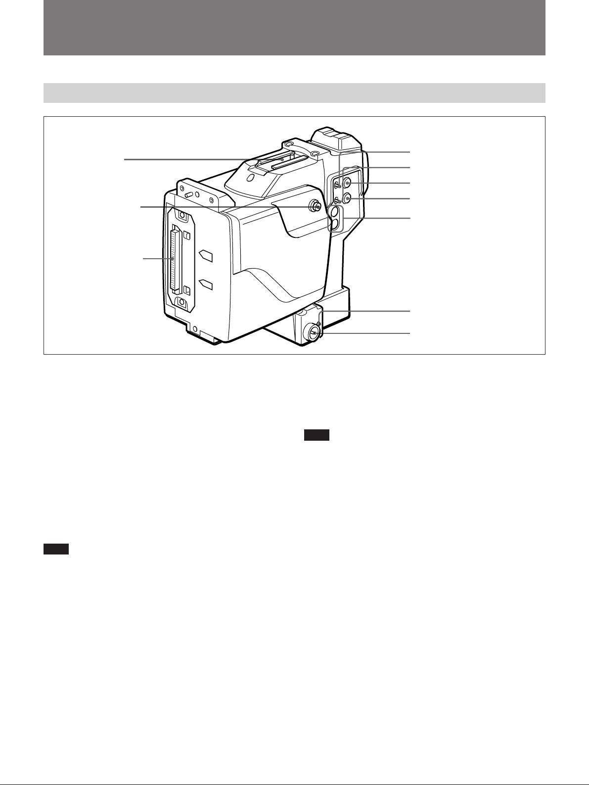
Front and Left Side
Accessory shoe
Shoulder strap fitting
1 Camera connector
1 Camera connector (PRO 76-pin DIGITAL or
PRO 50-pin)
Connects to the camera’s VTR connector. Two types
of connectors are provided and can be replaced
according to the camera.
PRO 76-pin DIGITAL: Use this connector for
docking with the DXC-D30/D30P digital video
cameras.
PRO 50-pin: Use this connector for docking with the
DXC-637 series analog video cameras.
For details on replacing these connectors, see “Mounting
on video Camera” on page 11.
Note
Use a DXC-D30/D30P with ROM of ver. 1.1 or later.
For version check and ROM change, consult your
Sony dealer.
2 TALK switch
AAAAyA<H.L0.idx>
3 INTERCOM switch
4 INTERCOM knob
5 PROGRAM knob
6 RETURN 1/RETURN 2
buttons
7 BREAKER button
8 POWER switch
3 INTERCOM switch
Selects the channel for transferring intercom audio.
CH1: Selects CH1 (channel 1).
CH2: Selects CH2 (channel 2).
Note
When the LINE switch on the CCU-TX7/TX7P
Camera Control Unit is in the PRIV position, the
intercom operates only between the camera and the
camera control unit regardless of the INTERCOM
switch position.
4 INTERCOM knob
Adjusts the intercom audio reception level.
When using a DXC-D30/D30P, setting the TALK
switch 2 to REMOTE will enable the audio level
knob on the DXC-D30/D30P’s front panel to adjust
both the intercom audio and program audio levels.
2 TALK switch
Selects whether or not to transfer intercom audio from
the camera to the camera control unit.
ON: Transfers intercom audio from camera to camera
control unit.
OFF: Do not transfer intercom audio from camera to
camera control unit.
REMOTE: Transfers intercom audio from camera to
camera control unit only while the VTR START
button on camera or lens is being pressed.
5 PROGRAM knob
Adjusts the program audio reception level.
When using a DXC-D30/D30P camera, setting the
TALK switch 2 to REMOTE will enable this knob to
adjust the balance between the program audio and
intercom audio levels. Turn clockwise to raise the
program audio level, and turn counterclockwise to
raise the intercom audio level.
5
Page 6

Location and Function of Parts
6 RETURN 1/RETURN 2 buttons
1)
Select the return video signal
to be output from the
RETURN OUT connector and to the camera’s
viewfinder.
Press the RETURN 1 or RETURN 2 button to select
AAAAyA<H.L0.idx>
the return video signal 1 or return video signal 2 from
the camera control unit.
To show the shooting picture on the viewfinder screen,
release the button. The return video signal which
selected last is still output from the RETURN OUT
connector if the button is released.
7 BREAKER button
The power to this unit is cut off when the circuit
breaker is activated by a power source or connection
problem. After resolving the problem, press this button
to reset the breaker.
If the breaker gets activated even after correcting the
connection, contact your Sony dealer.
8 POWER switch
Turns this unit’s power supply on and off.
To power the unit, set the switch to EXT or CCU
according to the type of power source being used.
EXT Power supplied via an optional CMA-8A/8ACE AC
Adaptor connected to the DC IN connector (when
this unit is connected to a camera control unit via a
coaxial cable)
CCU Power supplied via camera control unit (when this
unit is connected to a camera control unit via a
triaxial cable)
Set this to OFF to turn off the power supply.
When this unit is connected to a camera control unit
via a triaxial cable, the following functions continue to
operate even after the power is turned off.
•Intercom communication
•On/off control of the back tally indicator (when
TALLY switch is ON)
•Calling via CALL button
..........................................................................................................................................................................................................
1) Return video: Video signals that are sent from a camera
to a camera control unit and returned to the same or
another camera so that the camera operators can check
the recorded image.
6
Page 7

Switches and Knobs on the Rear and Right Side
1 Cursor knobs
2 TALLY switch
3 Back tally indicator
4 CALL button 7 UHF portable tuner
taps
AAAAyA<H.L0.idx>
5 AUDIO SELECT (CH1/CH2) switches
6 MIC IN +48V (CH1/CH2) switch
1 Cursor knobs (for DXC-D30/D30P)
When the CURSOR switch 8 is set to A or B, this
adjusts the position and size of the box cursor that is
displayed in the viewfinder of the DXC-D30/D30P.
H-POSITION: Adjusts the horizontal position of the
box cursor.
V-POSITION: Adjusts the vertical position of the
box cursor.
WIDTH: Adjusts the width of the box cursor.
HEIGHT: Adjusts the height of the box cursor.
2 TALLY switch
Set this switch to the ON position to activate the back
tally indicator 3.
3 Back tally indicator (red)
When the TALLY switch 2 is in the ON position, this
indicator lights (in red) in response to this unit’s
operating status. It also lights when the CALL button
on the camera control unit or remote control panel has
been pressed.
8 CURSOR switch
Illustration: CA-TX7
4 CALL button
Press this button to call the operator of the camera
control unit or remote control panel. Pressing this
button lights the tally indicator (red) on the camera
control unit, on the remote control panel, and in the
camera’s viewfinder. This unit’s back tally indicator
3 also lights if the TALLY switch 2 is in the ON
position.
5 AUDIO SELECT (CH1/CH2) switches
Select the source for signals to be transferred via the
camera control unit’s channel 1 and channel 2.
CAMERA: Transfers audio from a microphone on
the camera to the camera control unit.
CA-MIC: Transfers audio from a microphone
connected to this unit’s MIC IN (CH1/CH2)
connector to the camera control unit.
CA-LINE: Transfers audio from a line output
connected to this unit’s MIC IN (CH1/CH2)
connector to the camera control unit.
7
Page 8

Location and Function of Parts
6 MIC IN +48V (CH1/CH2) switch
Selects whether or not to supply power to a
microphone connected via the MIC IN CH1 and CH2
connectors.
AAAAyA<H.L0.idx>
ON: Supplys +48-V power to microphone.
OFF: Do not supply power to microphone.
Leave this switch in the ON position when using a
1)
microphone of phantom powering
type.
7 UHF portable tuner taps
When using an optional WRR-810A UHF Portable
Tuner, attach the holder and bracket (supplied with
the WRR-810A) for the portable tuner mounting
adapter.
For details of attaching and using the WRR-810A, see the
Operating Instructions for the WRR-810A.
8 CURSOR switch (for DXC-D30/D30P)
Selects whether or not to display a box cursor in the
DXC-D30/D30P Color Video Camera’s viewfinder.
B: Displays box cursor B.
A: Displays box cursor A.
OFF: No box cursor is displayed.
Note
No cursor is displayed in the viewfinder when using a
DXC-637 series camera.
..........................................................................................................................................................................................................
1) Phantom powering: Powering method for operating
condenser microphones by supplying power via a bias
power source and an amplifier. Because no DC voltage
is present in the audio channel, it is called “phantom
powering”.
8
Page 9

Connectors on the Rear and Right Side
1 INTERCOM/PROGRAM connector
2 PROMPTER OUT connector
AAAAyA<H.L0.idx>
5 CCU connector
6 DATA connector
3 RETURN OUT connector
4 MIC IN (CH1/CH2) connectors
1 INTERCOM/PROGRAM connector (XLR
5-pin, male)
Connect a headset for monitoring intercom audio or
program audio. Normally, a monaural (one-side)
headset should be connected.
An internal adjustment can be made to enable both
sides of the headset to receive audio, with intercom
audio on the left side and program audio on the right
side.
Contact your Sony dealer for further information on this
internal adjustment.
2 PROMPTER OUT (teleprompter video signal
output) connector (BNC type)
1)
Outputs teleprompter video signals
from the camera
control unit. (This unit can treat color teleprompter
video signals.)
If you have made the internal adjustment to change the
teleprompter video signal transfer direction so that
signals are transferred from this unit to the camera
control unit, this connector becomes the input
connector for teleprompter video signals.
7 DC OUT connector
8 DC IN connector
Illustration: CA-TX7
Contact your Sony dealer for further information on the
internal adjustment to change the teleprompter video signal
transfer direction.
3 RETURN OUT (return video signal output)
connector (BNC type)
Outputs return video signals from a camera control
unit. Use the RETURN 1 and RETURN 2 buttons to
switch between the two return video signals.
4 MIC IN (CH1/CH2) (MIC inputs, channel 1 and
channel 2) connectors (XLR 3-pin, female)
Connect external microphones or other equipment as
sources for audio to be transferred to the camera
control unit’s channel 1 or 2.
Set the AUDIO SELECT (CH1/CH2) switch to select
the channel for the connected equipment.
..........................................................................................................................................................................................................
1) Teleprompter video signals: Video signals for prompter
which displays scripts in the television monitor by the
camera lens or on the face of a one-way mirror
positioned directly in front of the camera lens so that
performers can read scripts while looking into the
camera lens.
9
Page 10

Location and Function of Parts
5 CCU (Camera control unit) connector (CATX7: Kings triaxial connector, CA-TX7P: Fischer
triaxial connector)
Connect a camera control unit via a triaxial cable. In
addition to supporting signal transmission between this
AAAAyA<H.L0.idx>
unit and the connected camera control unit, the triaxial
cable enables this unit to receive its power supply via
the camera control unit.
Using a coaxial cable to connect the camera control
unit
The CCU connector must be refitted to enable
connection of a coaxial cable. Note that connecting a
coaxial cable makes it impossible for this unit to
receive power from the camera control unit. Use a
CMA-8A/8ACE AC Adaptor for AC power sources.
Contact your Sony dealer for more information on refitting
the CCU connector.
6 DATA connector (10-pin)
Outputs control signals for the lens (focus or zoom
control) and the tripod head (panning or tilting) that
are sent from a remote control panel connected to the
camera control unit.
For further information about using this connector, consult
your Sony dealer.
7 DC OUT connector (4-pin)
Use this connector when supplying power (DC 12V,
Max. 12 W) to a WRR-810A UHF Portable Tuner
(supplied separately) or an LCD teleprompter unit.
Note
Never connect a unit that has a power consumption
rating of more than 12 W.
8 DC IN connector (XLR 4-pin)
When connecting this unit to a camera control unit via
a coaxial cable, use this connector for a CMA-8A/
8ACE AC Adaptor (supplied separately). Use the
CCQX-3 DC power cord to connect the CMA-8A/
8ACE to this unit.
10
Page 11

Mounting on Video Camera
This unit is dockable with the DXC-D30/D30P digital video camera or
with a DXC-637 series analog video camera.
Replace the camera connector according to the camera to be used.
Using a DXC-D30/D30P : Use the PRO 76-pin DIGITAL connector.
Using a DXC-637 series camera : Use the PRO 50-pin connector.
Note
Turn the POWER switch off before mounting the unit on the camera.
Using the DXC-D30/D30P
Replace the PRO 50-pin connector with the PRO 76-pin DIGITAL
connector.
1 Loosen the two screws (M3)
and remove the cover from the
PRO 50-pin connector.
AAAAyA<H.L0.idx>
Note
Never loosen the other screws.
2 Press the right side of the PRO
50-pin connector until the PRO
76-pin DIGITAL connector
appears.
The both connectors swing to
switch the positions by
pressing either of them.
PRO 50-pin connector
Cover
PRO 50-pin connector PRO 76-pin DIGITAL connector
(Continued)
11
Page 12

Mounting on Video Camera
3 Attach the cover upside down.
Make sure that the match mark
lines up with “PRO 76P
AAAAyA<H.L0.idx>
DIGITAL” indication.
Using the DXC-637 series camera
Match mark
PRO76P
DIGITAL
Replace the PRO 76-pin DIGITAL connector with the PRO 50-pin
connector. Press the left side of the PRO 76-pin DIGITAL connector until
the PRO 50-pin connector appears. Make sure that the match mark lines
up with “PRO 50P” indication.
Mounting on the camera
1 If necessary, replace the PRO
50-pin connector with the PRO
76-pin DIGITAL connector.
For details, see “Using the DXCD30/D30P” (page 11).
This section describes the procedure for mounting this unit on a DXCD30/D30P. Use the same procedure for mounting on a DXC-637 series
camera. (Replace the PRO 76-pin DIGITAL connector with the PRO 50pin connector.)
PRO 76-pin DIGITAL connector
12
Page 13

2 Fit the projection on the
bottom of this unit into the slot
on the camera.
3 Slide the unit along the groove
on the camera, and press firmly
until fixed.
Camera
Slot
Groove
AAAAyA<H.L0.idx>
Projection
4 Tighten the two screws (M4 ×
12) in the figure.
M4 × 12 screws
(Continued)
13
Page 14

Mounting on Video Camera
5 Tighten the two screws (M4 ×
6) to fix the shoulder pad.
AAAAyA<H.L0.idx>
Note
Slide the shoulder pad to its
central position before
tightening the screws.
Otherwise the screws may not
be properly fixed.
Removing from the camera
Follow the procedure above in reverse.
Notes on Use
Use and storage locations
Avoid using or storing the unit in the following places:
•Where it is subject to extremes of temperature
(operating temperature: –10ºC to +45ºC (14ºF to
113ºF)).
Note that in summer the temperature in a car with the
windows closed can reach 50ºC (122ºF).
•Very damp or dusty places.
•Where rain is likely to reach the unit.
•Places subject to severe vibration.
•Near strong magnetic fields
•Near transmitting stations generating strong radio
waves.
Avoid violent impacts
Dropping the unit, or otherwise imparting a violent
shock to it, is likely to cause it to malfunction.
M4 × 6 screws
Do not cover with cloth
While the unit is in operation, do not cover it with a
cloth or other material. This can cause the temperature
to rise, leading to a malfunction.
After use
Turn the POWER switches on the unit and camera
control unit off.
Care
If the body of the unit is dirty, wipe it with a dry
cloth. For severe dirt, use a soft cloth steeped in a
small amount of neutral detergent, then wipe dry.
Do not use volatile solvents such as alcohol or
thinners, as these may damage the finish.
14
Page 15

Specifications
General
Power requirements
When supplied via the CCU
connector: 120 V AC
When supplied via the DC IN
connector: 12 V DC (10.5 to 17
V DC)
Power consumption
Varies according to connected
equipment as shown in the
following tables
When power is supplied via the CCU connector
CA-TX7/TX7P 10.5 W
CA-TX7/TX7P+DXC-
D30/D30P
CA-TX7/TX7P+DXC-
D30/D30P+DXF-701/
701CE
CA-TX7/TX7P+DXCD30/D30P+DXF-51/
51CE
CA-TX7/TX7P
outputting 12 W from
the DC OUT
connector+DXC-D30/
D30P+DXF-51/51CE
1)
:
Power consumption
CA-TX7/TX7P CA-TX7/TX7P
11 W 23.7 W
11.2 W 26 W
12.3 W 35 W
13.3 W
and connected
equipment
48 W
When power is supplied via the DC IN connector
Power consumption
CA-TX7/TX7P CA-TX7/TX7P
and connected
equipment
CA-TX7/TX7P 7.5 W
CA-TX7/TX7P+DXC-
D30/D30P
CA-TX7/TX7P+DXC-
D30/D30P+DXF-701/
701CE
CA-TX7/TX7P+DXCD30/D30P+DXF-51/
51CE
CA-TX7/TX7P
outputting 12 W from
the DC OUT
connector+DXC-D30/
D30P+DXF-51/51CE
7.5 W 20.2 W
7.5 W 22.3 W
7.5 W 30.2 W
7.5 W 42.2 W
Operating temperature
–10ºC to +45ºC (14°F to 113°F)
Operating humidity
20% to 90%
Storage temperature
–20ºC to +60ºC (–4ºF to 140ºF)
Mass Approx. 2.7 kg (5 lb 15 oz)
External dimensions
226 × 221 × 131 mm (9 × 8
1
/4 inches) (w/h/d)
3
/4 × 5
..........................................................................................................................................................................................................
1) The power consumption indicated on the name plate of
the unit is total consumption of the CA-TX7/TX7P
outputting 12 W from the DC OUT connector, DXCD30/D30P, and DXF-51/51CE.
15
Page 16

Specifications
Input/output connectors
CCU CA-TX7: Kings triaxial connector
(made by Lemo)
CA-TX7P: Fischer triaxial
connector
PROMPTER OUT
BNC, 1.0 Vp-p, 75 Ω
RETURN OUT BNC, 1.0 Vp-p, 75 Ω
INTERCOM/PROGRAM
XLR 5-pin
Input level: –60 dBs (dynamic)
Output level: –∞ to +12 dBs
MIC IN 1,2 XLR 3-pin, female, 600 Ω,
balanced
Input level: –60 dB (for
microphone input) or –20 dB (for
line input)
DC IN XLR 4-pin, 10.5 to 17 V DC
DC OUT 4-pin, 10.5 to 17 V DC, max. 12 W
DATA 10-pin
Analog: 0 to 5 V DC × 4
Digital: 0 or 5 V DC × 2
Camera connector
PRO 76-pin DIGITAL or PRO 50-
pin
Accessories supplied
Operating instructions (1)
Accessories not supplied
Triaxial cable (Belden)
CCQX-3 DC Power Cord
CMA-8A/8ACE AC Adaptor
WRR-810A UHF Portable Tuner
Design and specifications are subject to change
without notice.
Sony Corporation Printed in Japan
 Loading...