

Sony Car Stereo System XR-M510 Service Manual
SERVICE MANUAL
FM/MW/LW CASSETTE CAR STEREO
AEP Model
UK Model
E Model
XR-M510
Ver 1.0 2000.12
9-870-230-11 Son
y Corporation
2000L0553-1 Audio Entertainment Group
C 2000.12 General Engineering Dept.
SPECIFICATIONS
Dolby noise reduction manufactured under license from
Dolby Laboratories.
“DOLBY” and the double-D symbol ; are trademarks
of Dolby Laboratories.
General
Outputs Audio output (2)
Power aerial relay control
lead
Power amplifier control
lead
Inputs Telephone ATT control
lead
Illumination control lead
Tone controls Bass ±9 dB at 100 Hz
Treble ±9 dB at 10 kHz
Power requirements 12 V DC car battery
(negative earth)
Dimensions Approx. 178 × 50 × 182 mm
(w/h/d)
Mounting dimensions Approx. 182 × 53 × 163 mm
(w/h/d)
Mass Approx. 1.3 kg
Supplied accessories Card remote commander
RM-X96
Parts for installation and
connections (1 set)
Design and specifications are subject to change
without notice.
Cassette player section
Tape track 4-track 2-channel stereo
Wow and flutter 0.08 % (WRMS)
Frequency response 30 – 20,000 Hz
Signal-to-noise ratio
Tuner section
FM
Tuning range 87.5 – 108.0 MHz
Aerial terminal External aerial connector
Intermediate frequency 10.7 MHz/450kHz
Usable sensitivity 8 dBf
Selectivity 75 dB at 400 kHz
Signal-to-noise ratio 66 dB (stereo),
72 dB (mono)
Harmonic distortion at 1 kHz
0.6 % (stereo),
0.3 % (mono)
Separation 35 dB at 1 kHz
Frequency response 30 – 15,000 Hz
MW/LW
Tuning range MW: 531 – 1,602 kHz
LW: 153 – 279 kHz
Aerial terminal External aerial connector
Intermediate frequency 10.7 MHz/450 kHz
Sensitivity MW: 30 µV
LW: 40
µ
V
Power amplifier section
Outputs Speaker outputs
Speaker impedance 4 – 8 ohms
Maximum power output 50 W × 4 (at 4 ohms)
Dolby NR off
61 dB
58 dB
Dolby B NR
67 dB
64 dB
Cassette type
TYPE II, IV
TYPE I
Model Name Using Similar Mechanism WX-C5000/XR-M500R
Tape Transport Mechanism T ype MG-25E-136

2
XR-M510
TABLE OF CONTENTS
1. SERVICING NOTES............................................... 3
2. GENERAL
Location of Controls ....................................................... 4
Setting the Clock ............................................................. 4
Changing the Sound and Display Settings ..................... 5
Installation....................................................................... 5
Connections ..................................................................... 6
3. DISASSEMBLY ......................................................... 10
4. ASSEMBLY................................................................. 14
5. MECHANICAL ADJUSTMENTS ....................... 19
6. ELECTRICAL ADJUSTMENTS
Tape Deck Section .......................................................... 19
Tuner Section .................................................................. 20
7. DIAGRAMS
7-1. Block Diagram – TUNER/TAPE Section – .................. 21
7-2. Block Diagram – MAIN Section – ................................ 22
7-3. Block Diagram
– DISPLAY/BUS CONTROL Section – ....................... 23
7-4. Block Diagram – POWER SUPPLY Section – ............. 24
7-5. Note for Printed Wiring Boards and
Schematic Diagrams ....................................................... 25
7-6. Printed Wiring Boards
– MAIN Board (Component Side) – .............................. 26
7-7. Printed Wiring Boards
– MAIN Board (Conductor Side) – ................................ 27
7-8. Schematic Diagram – MAIN Board (1/4) – .................. 28
7-9. Schematic Diagram – MAIN Board (2/4) – .................. 29
7-10. Schematic Diagram – MAIN Board (3/4) – .................. 30
7-11. Schematic Diagram – MAIN Board (4/4) – .................. 31
7-12. Printed Wiring Boards –SUB Board –........................... 32
7-13. Schematic Diagram – SUB Board –.............................. 33
7-14. Printed Wiring Boards – DISPLAY Board –................. 34
7-15. Schematic Diagram – DISPLAY Board – ..................... 35
7-16. IC Pin Function Description ........................................... 38
8. EXPLODED VIEWS................................................ 45
9. ELECTRICAL PARTS LIST ............................... 49
Flexible Circuit Board Repairing
• Keep the temperature of the soldering iron around 270 ˚C during repairing.
• Do not touch the soldering iron on the same conductor of the
circuit board (within 3 times).
• Be careful not to apply force on the conductor when soldering
or unsoldering.
Notes on chip component replacement
• Never reuse a disconnected chip component.
• Notice that the minus side of a tantalum capacitor may be damaged by heat.
3
XR-M510
R625
R626
R719
R720
IC601
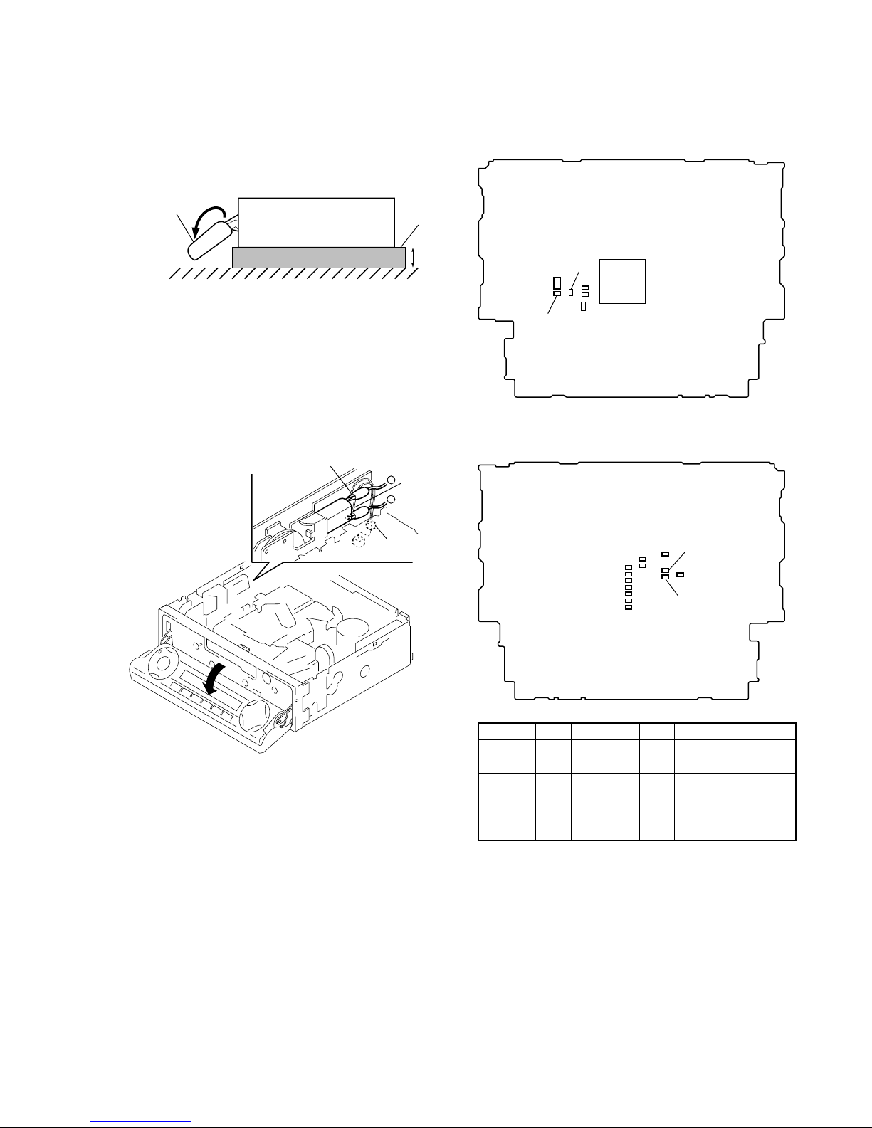
SECTION 1
SERVICING NOTES
PRECAUTION ON OPEN/CLOSE FRONT PANEL
The front panel opens to the bottom of main unit.
In performing the repair, place the main unit on the base having
the height exceeding 1 cm.
Open the front panel by supplying the power through the following steps:
1. Disconnect the motor connector (CN501) from main board.
2. Supply the power to the motor.
Voltage : 9 V
Yellow wiring: MOTOR –
Black wiring : MOTOR +
front panel
XR-M510
( SIDE VIEW)
1cm
base
black wiring
yellow
wiring
connector
(CN501)
–
+
MODEL IDENTIFICATION
There are three types of main board in according of destination.
– MAIN Board (Component Side) –
– MAIN Board (Conductor Side) –
R625 R626 R719 R720 Indicated language
TYPE A aa ××
English, Spanish,
Swedish, Portuguese
TYPE B ××aa
French, German, Dutch,
Italian
South
a ××a
English, Czeck, Polish,
European Turkish
TYPE A, B, or South European model can also be identified from
the front panel display language.
For a switching method of display language, see page 5.
4
XR-M510
SECTION 2
GENERAL
This section is extracted from
instruction manual.
6
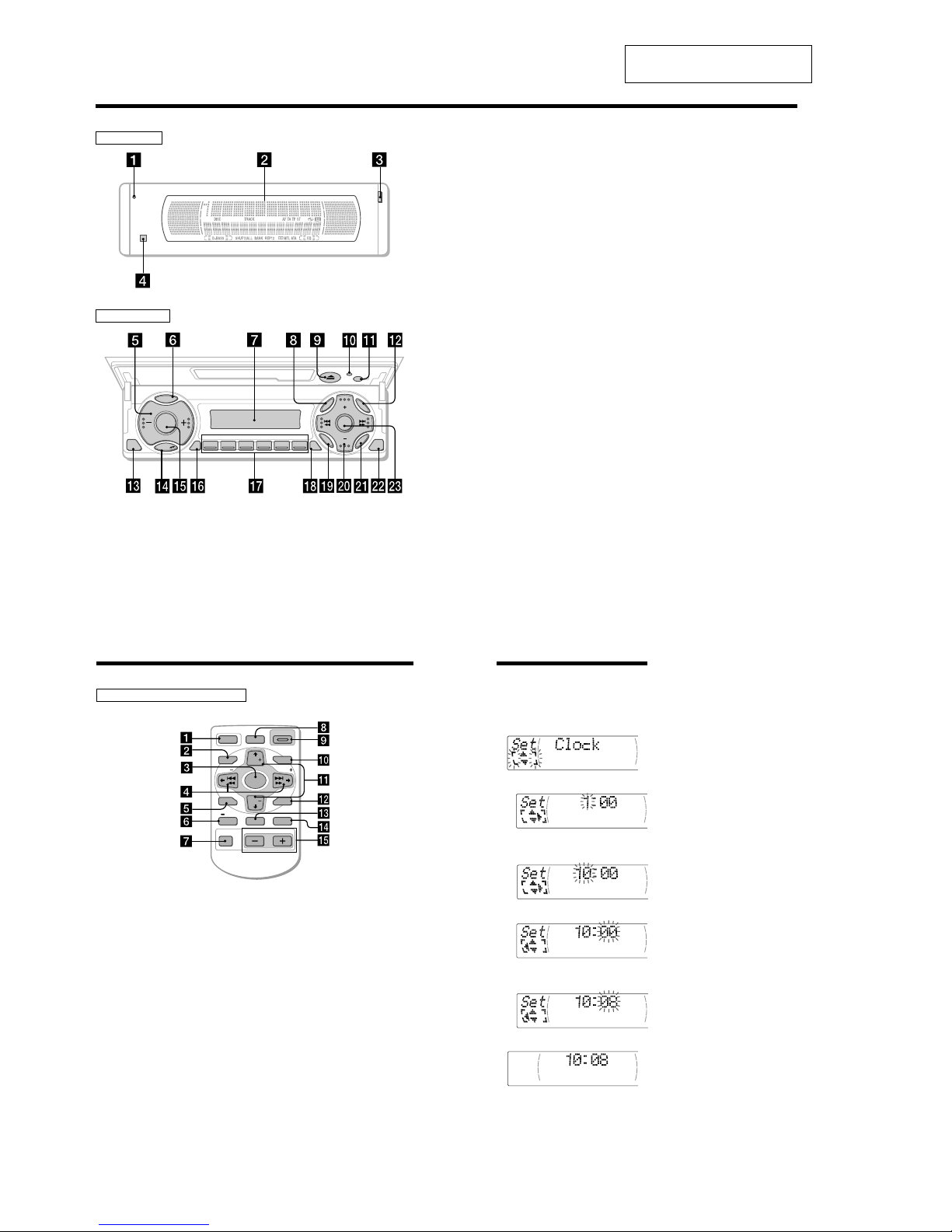
Location of controls
SOURCE
123456
CLOSE
OFF
DISC
DISC
EN
TER
SOU
ND
MEN
U
LIST
REP SHUF
D
S
P
L
P
T
Y
M
O
D
E
XR-M510
TAAF
D-BASS
Securit y side
Operation side
7
qk TA button 16, 17, 18
ql SOUND button
w; PRST/DISC +/– (cursor up/down) buttons
SEEK/AMS –/+ (cursor left/right) buttons
13
wa ENTER button
ws CLOSE button
wd D-BASS button
* Warning w hen installing in a car
without ACC (accessory) posit ion on
the ignition key swit ch
Be sure to press (OFF) on the unit for
two seconds to turn off the clock display
after turning off the engine.
When you press (OFF) only momentarily,
the clock display does not turn off and this
causes battery wear.
The corresponding but tons of the unit
control the same functions as those on
the card rem ote commander.
10 Reset button 8
2 Main display window
3 OPEN button 38
4qa Receptor for the card remote
commander
5 Volume adjust buttons
6 DSPL/PTY (display mode change/
programme type) button
7 Sub display window
8 MENU button
9
Z (eject) button 11
qs LIST button
qd OFF button*
9
qf MODE button
qg SOURCE (TUNER/TAPE/CD/MD) button
qh AF button 16, 18
qj Number buttons
During radio reception:
Preset number select
13, 14, 17, 33, 34
During tape playback:
(1) REP 12
During CD/MD playback:
(1) REP 28
(2) SHUF 28
5
OFF
D-BASS
SEEK
PTY
SEEK
MENU LIST
SOUND
ENTER
DISC
DISC
SOURCE
DSPL AF/TA MODE
VOLATT
OPEN/CLOSE
Location of controls
Refer to the pages listed for details.
1 OFF button 9, 11
2 MENU button 10, 12, 13, 14, 16, 18, 20,
24, 25, 27, 28, 29, 31, 33, 34, 36
3 SOURCE (TUNER/TAPE/CD/MD) button
9, 11, 13, 14, 25, 26, 30, 32, 33
4 </, (SEEK/AMS –/+) buttons
9, 10, 11, 12, 14, 16, 20, 23, 24, 25, 27, 28,
29, 31, 32, 34, 36
Automatic Music Sensor (./>)
11, 27
Manual search (m/M) 27
Seek 14
5 SOUND button 23
6 DSPL/PTY (display mode change/
programme type) button
19, 26, 27, 29, 36
7 ATT (attenuate) button 23
8 D-BASS button 24
9 OPEN/CLOSE button 11
0 LIST button 29, 30, 35
qa M/m (DISC/PRST +/–) buttons
9, 10, 12, 13, 14, 16, 18, 19, 20, 24, 25,
27, 28, 29, 30, 31, 32, 33, 34, 36
During radio reception:
Preset stations select 14
During CD/MD playback:
Disc change 27
qs ENTER button 10, 12, 13, 14, 16, 18, 19,
20, 24, 25, 27, 29, 30, 31, 33, 34, 35, 36
qd AF/TA button 16, 17, 18
qf MODE button
11, 12, 13, 14, 26, 30, 32, 33
During tape playback:
Playback direction change 11
During radio reception:
BAND select 13, 14
During CD/MD playback:
CD/MD unit select 26
qg VOL (Volume adjust) buttons
A unit turned off by pressing (OFF) for two
seconds cannot be operated with the card
remote commander unless (SOURCE) on the
unit is pressed or a cassette is inserted to
activate the unit first.
Card remote commander RM-X96
10
Tips
• You can use the convenient CT function to set
the clock automatically (page 20).
• When the D.Info mode is set to “ on,” t he ti me is
always displayed (except for some functions of
SA mode) (page 23).
Setting the clock
The clock uses a 24-hour digital indication.
Example: To set the clock to 10:08
1 Press (MENU), then M or m repeatedly
until “Clock” appears.
1 Press (ENTER).
The hour indication flashes.
2 Press M or m to set the hour.
3 Press ,.
The minute indication flashes.
4 Press M or m to set the minute.
2 Press (ENTER).
The clock starts.

5
XR-M510
15 cm
Εγκατάσταση
Προφυλάξεις
• Εάν τοποθετήσετε αυτή τη συσκευή
µαζί µε άλλο εξοπλισµ της Sony,
είναι καλύτερα να τοποθετήσετε τη
συσκευή στην κάτω θέση.
• Πρέπει να υπάρχει µια απσταση
τουλάχιστον 15 εκ. µεταξύ της
υποδοχής κασέτας της συσκευής και
του µοχλού ταχυτήτων, ώστε να
υπάρχει επαρκής χώρος για την
εύκολη εισαγωγή της κασέτας.
Επιλέξτε τη θέση εγκατάστασης µε
προσοχή, ώστε η συσκευή να µην
εµποδίζει στην αλλαγή ταχυτήτων ή
άλλους χειρισµούς οδήγησης.
•
Οταν η πρσοψη είναι ανοικτή, ένα
τµήµα της θα προεξέχει απ τη
συσκευή προς τα κάτω. Οταν
εγκαταστήσετε τη συσκευή,
βεβαιωθείτε τι αυτ το τµήµα της
πρσοψης δεν παρεµποδίζεται ενώ
βρίσκεται σε ανοικτή θέση (για
παράδειγµα απ το σταχτοδοχείο).
• Επιλέξτε προσεκτικά τη θέση
εγκατάστασης έτσι ώστε η συσκευή
να µην παρεµβάλλεται στις συνήθεις
κινήσεις οδήγησης.
• Αποφύγετε την εγκατάσταση της
συσκευής σε σηµεία υποκείµενα σε
υψηλές θερµοκρασίες, πως στον
ήλιο ή σε αεραγωγούς του
καλοριφέρ, ή σε σηµεία υποκείµενα
σε σκνη, βρωµιά ή υπερβολικές
δονήσεις.
• Για ασφαλή και σίγουρη
εγκατάσταση χρησιµοποιείτε µνο
τα παρεχµενα υλικά τοποθέτησης.
Ρύθµιση γωνίας τοποθέτησης
Ρυθµίστε τη γωνία τοποθέτησης σε
λιγτερο απ 20°.
Extended portion of the front panel.
Parte sobresaliente del panel frontal.
Utskjutande del av frontpanelen.
Parte extensível do painel frontal.
Προεξέχον τµήµα της πρσοψης.
8.5 mm
15.5 mm
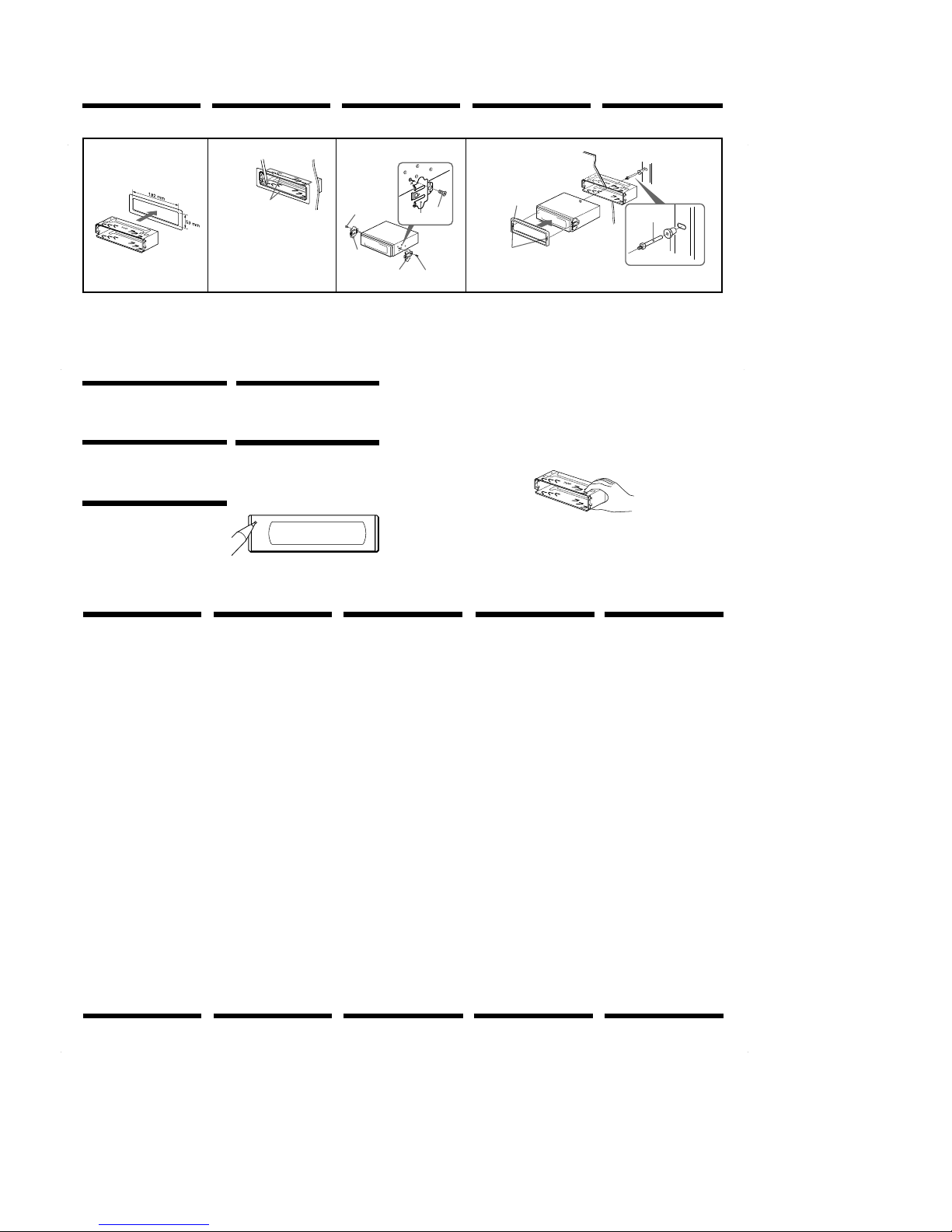
Installation
Precautions
•If you mount other Sony equipment
with this unit, it is better to mount this
unit in the lower position.
•There must be a distance of at least 15
cm between the cassettes slot of the
unit and shift lever to insert cassette
easily. Choose the installation location
carefully so the unit does not interfere
with gear shifting and other driving
operations.
•When the front panel is open, a
portion of it will extend down from the
unit. When you install the unit, make
sure that this portion of the front panel
is not obstructed in its open position
(by the ashtray, for example).
•Choose the installation location
carefully so that the unit will not
interfere with normal driving
operations.
•Avoid installing the unit in areas
subject to dust, dirt, excessive
vibration, or high temperatures, such
as in direct sunlight or near heater
ducts.
•Use only the supplied mounting
hardware for a safe and secure
installation.
Mounting angle adjustment
Adjust the mounting angle to less than
20°.
Instalación
Precauciones
•Si monta otro equipo Sony con esta
unidad, es preferible montar esta
unidad en la posición más baja.
•Para que sea posible insertar la cinta
con facilidad, debe haber una
distancia de al menos 15 cm entre la
ranura de inserción de cintas de la
unidad y la palanca de cambios.
Instale la unidad en un lugar que no
entorpezca las operaciones de cambio
de marchas o de conducción en
general.
•Cuando el panel frontal está abierto,
una parte de él sobresaldrá de la
unidad. Cuando instale la unidad,
compruebe que dicha parte del panel
frontal no queda obstruida en la
posición de apertura (debido al
cenicero, por ejemplo).
•Elija cuidadosamente el lugar de
montaje de forma que la unidad no
interfiera las funciones normales de
conducción.
•Evite instalar la unidad donde pueda
quedar sometida a altas temperaturas,
como a la luz solar directa o al aire de
calefacción, o a polvo, suciedad, o
vibraciones excesivas.
•Para realizar una instalación segura y
firme, utilice solamente la ferretería de
montaje suministrada.
Ajuste del ángulo de montaje
Ajuste el ángulo de montaje a menos de
20°.
Montering
Säkerhetsföreskrifter
•Om du monterar annan Sonyutrustning till denna enhet är det bäst
att montera denna enhet i det undre
läget.
•För att du ska kunna sätta i och ta ut
bandet måste avståndet vara minst 15
cm mellan kassettfacket på enheten
och växelspaken. När du installerar
enheten väljer du en plats så att
enheten inte är i vägen när du kör.
•När frontpanelen är öppen befinner
sig en liten del av den under enhetens
bottenplan. Se till att du installerar
enheten så att den här delen går fri
(från t.ex. askkoppen) när frontpanelen
är öppen.
•Var noga när du väljer var i bilen du
monterar bilstereon, så att den inte
sitter i vägen när du kör.
•Montera inte bilstereon där den utsätts
för värme,
t ex solsken eller varmluft, eller där
den utsätts för damm, smuts och/eller
vibrationer.
•Använd endast de medföljande
monteringstillbehören för att vara
säker på att bilstereon monteras på ett
säkert och korrekt sätt.
Tillåten monteringsvinkel
Monteringsvinkeln får inte vara större
än 20 grader.
Instalação
Precauções
•É preferível montar este aparelho na
posição mais baixa, se quiser montar
simultaneamente outros equipamentos
da Sony.
•Para colocar com facilidade a cassete,
deve haver uma distância de pelo
menos 15 cm entre a ranhura de
introduçäo da cassete e a alavanca das
mudanças.
Escolha o local de instalaçäo de forma
a que o aparelho näo interfira com as
mudanças de velocidade ou com as
outras manobras de conduçäo.
•Quando o painel frontal estiver aberto,
pode puxar a parte extensível baixo.
Quando instalar a unidade, verifique
se essa parte do painel frontal não está
presa na posição aberta (pelo cinzeiro,
por exemplo).
•Escolha com cuidado um local
apropriado para a montagem do
aparelho, para que este não interfira
com as manobras necessárias à
condução do veículo.
•Evite instalar o aparelho onde possa
estar sujeito a altas temperaturas,
como em locais expostos directamente
à luz do sol, ao ar quente dos
aquecimentos, ou sujeitos a pó,
sujidade ou vibração excessiva.
•Para efectuar uma instalação segura
utilize unicamente o hardware de
montagem fornecido.
Ajuste do ângulo de montagem
Ajuste o ângulo de montagem a menos
de 20°.
23
Changing the sound and
display settings
The following items can be set:
Set (Sett ing)
•Clock (page 10).
•CT (Clock Time) (page 20).
•Beep — to turn the beep sound on or off.
•RM (Rotary Commander) — to change the
operative direction of the rotary commander.
— Select “norm” to use the rotary
commander as the factory-set position.
— Select “rev” when you mount the rotary
commander on the right side of the
steering column.
•English/Spanish/Portuguese/Swedish — to
change the display language to English,
Spanish, Portuguese or Swedish.
Dis (Displ ay)
•D.Info (Dual Information) — to display the
clock and the play mode simultaneously (on),
or to display the information alternately (off).
•
SA (Spectrum Analyzer) — to change the
display pattern of the equalizer display
(page 25).
•Dimmer — to change the brightness of the
display (When the Illumination terminal
connected).
— Select “on” to dim the display.
— Select “off” to deactivate Dimmer.
•Contrast — to adjust the contrast if the
indications in the display are not
recognisable because of the unit’s installed
position.
•M.Dspl (Motion Display) — to turn the
motion display on or off.
•A.Scrl (Auto Scroll) (page 27).
continue to next page t
24
1 Press (MENU).
2 Press M or m repeatedly until the desired
item appears.
Each time you press m, the item changes as
follows:
Example
Clock t CT t Beep t RM t English/
Spanish/Portuguese/Swedish t D.Info t SA
t Dimmer t Contrast t M.Dspl*
1
t A.Scrl*
2
*1When no CD or MD i s playing, t his item will
not appear.
*
2
When the rad io is off, or when no tape, CD,
or M D is playing , this item will not appear.
Note
The displayed item w ill differ depending on the
source.
Tip
You can easily switch among categories (“Set,”
“ Snd” (Sound), “P/M” (Play Mode) and “Dis”) by
pressing M or m for two seconds.
3 Press , to select the desired setting
(Example: on or off).
4 Press (ENTER).
After the mode setting is complete, the
display returns to normal playback mode.
6
XR-M510
Συνδέσεις
Προσοχή
• Αυτή η συσκευή έχει σχεδιαστεί να
λειτουργεί µνο µε τροφοδοσία απ
µπαταρία αυτοκινήτου 12 V DC µε
αρνητική γείωση.
• Προσέξτε να µην µαγκώσετε κάποιο
καλώδιο µεταξύ του σώµατος του
αυτοκινήτου και κάποιας βίδας ή
της συσκευής, ή µεταξύ
οποιωνδήποτε κινούµενων
τµηµάτων πως για παράδειγµα στη
ράγα του καθίσµατος.
• Συνδέστε το καλώδιο τροφοδοσίας
8 στη συσκευή και τα ηχεία πριν το
συνδέσετε στην υποδοχή
βοηθητικής τροφοδοσίας.
• Συνδέστε λα τα καλώδια γείωσης
σε µια κοινή γη.
• Συνδέστε το κίτρινο καλώδιο σε ένα
ελεύθερο κύκλωµα του
αυτοκινήτου µε ονοµαστική τιµή
έντασης µεγαλύτερη της
αναγραφµενης στην ασφάλεια της
συσκευής. Αν συνδέσετε τη
συσκευή αυτή σε συνδυασµ µε
άλλες στερεοφωνικές συσκευές
ήχου, θα πρέπει η ονοµαστική τιµή
της έντασης του κυκλώµατος του
αυτοκινήτου που θα συνδεθεί να
είναι µεγαλύτερη απ το άθροισµα
των εντάσεων των επιµέρους
ασφαλειών. Αν δεν υπάρχει
κύκλωµα στο αυτοκίνητο µε τσο
µεγάλη ονοµαστική τιµή έντασης,
συνδέστε τη συσκευή απ’ ευθείας
στην µπαταρία. Αν δεν υπάρχει
ελεύθερο διαθέσιµο κύκλωµα για τη
σύνδεση της συσκευής, συνδέστε
τη συσκευή σε κάποιο κύκλωµα
µεγαλύτερης ονοµαστικής τιµής
έντασης απ την αναγραφµενη
στην ασφάλεια της συσκευής, µε
τέτοιο τρπο ώστε αν καεί η
ασφάλεια της συσκευής να µην
αποκοπεί άλλο κύκλωµα.
Προειδοποίηση για την
εγκατάσταση σε
αυτοκίνητο χωρίς θέση
ACC (βοηθητική) στον
διακπτη ανάφλεξης
Βεβαιωθείτε τι πιέσατε το πλήκτρο
(OFF) της συσκευής για δύο
δευτερλεπτα ώστε να
απενεργοποιήσετε την ένδειξη του
ρολογιού αφού σβήσετε τη µηχανή
του αυτοκινήτου.
Αν πιέσετε το πλήκτρο (OFF)
στιγµιαία µνο, η ένδειξη του
ρολογιού δεν απενεργοποιείται και
έτσι προκαλείται φθορά στην
µπαταρία του αυτοκινήτου.
Connections
Cautions
•This unit is designed for negative earth
12 V DC operation only.
•Be careful not to pinch any wires
between a screw and the body of the
car or this unit or between any moving
parts such as the seat railing, etc.
•Connect the power connecting cord 8
to the unit and speakers before
connecting it to the auxiliary power
connector.
•Run all earth wires to a common
earth point.
•Connect the yellow cord to a free car
circuit rated higher than the unit’s fuse
rating. If you connect this unit in
combination with other stereo
components, the car circuit they are
connected to must be rated higher than
the sum of the individual components’
fuse rating. If there are no car circuits
rated as high as the unit’s fuse rating,
connect the unit directly to the battery.
If no car circuits are available for
connecting this unit, connect the unit
to a car circuit rated higher than the
unit’s fuse rating in such a way that if
the unit blows its fuse, no other circuits
will be cut off.
Conexiones
Precauciones
•Esta unidad ha sido diseñada para
alimentarse con 12 V CC, negativo a
masa, solamente.
•Tenga cuidado de no atrapar ningún
cable entre algún tornillo y la
carrocería del automóvil o esta unidad
o entre las partes móviles, como por
ejemplo los raíles del asiento, etc.
•Conecte el cable de conexión de
alimentación 8 a la unidad y los
altavoces antes de conectarlo al
conector de alimentación auxiliar.
•Conecte todos los conductores de
puesta a masa a un punto común.
•Conecte el cable amarillo a un circuito
libre del automóvil de potencia
nominal superior a la del fusible de la
unidad. Si conecta esta unidad en
combinación con otros componentes
estéreo, la potencia nominal del
circuito del automóvil a los que dichos
componentes estén conectados debe
ser superior a la suma de la potencia
nominal del fusible de los
componentes. Si no existen circuitos de
automóvil de potencia nominal tan
alta como la del fusible de la unidad,
conecte ésta directamente a la batería.
Si no hay circuitos de automóvil
disponibles para conectar esta unidad,
conecte la misma a un circuito de
automóvil de potencia nominal
superior a la del fusible de la unidad
de forma que no se desactiven otros
circuitos si el fusible de dicha unidad
se funde.
Anslutning
Säkerhetsföreskrifter
•Denna bilstereo är endast avsedd för
anslutning till ett negativt jordat, 12 V
bilbatteri.
•Var noga med att inga kablar kläms
mellan någon skruv eller att de blir
klämda mellan rörliga delar som t.ex.
bilsätet.
•Anslut strömkabeln 8 till enheten och
högtalarna innan du ansluter den till
den yttre strömanslutningen.
•Dra samtliga jordledningar till en
och samma jordningspunkt.
•Anslut den gula kabeln till en ledig
bilkrets med ett högre amperetal än
enhetens. Om du kopplar både denna
enhet och andra stereokomponenter till
en och samma bilkrets, måste den
bilkrets de kopplas till ha en högre
ampere än summan av de enskilda
delarnas amperestyrka. Om det inte
finns några bilkretsar med en så hög
amperestyrka som enhetens ska du
ansluta enheten direkt till batteriet. Om
inga bilkretsar finns för anslutning till
enheten ska du ansluta enheten till en
bilkrets med ett högre amperetal än
enhetens säkring, så att det är denna
som går i stället för bilens.
Ligações
Cuidado
•Este aparelho foi concebido para
funcionar somente com corrente
contínua de 12 V com negativo à
massa.
•Tenha cuidado para que os fios não
fiquem entalados entre os parafusos e
a carroçaria do automóvel ou a caixa
do aparelho, nem entre as peças
móveis, por exemplo, as calhas dos
bancos, etc.
•Ligue o cabo de alimentação de
corrente 8 ao aparelho e aos
alifalantes antes de o ligar ao conector
de corrente auxiliar.
•Ligue todos os cabos de massa num
ponto de massa comum.
•Ligue o cabo amarelo a um circuito
eléctrico livre do automóvel, cuja
potência nominal seja superior à dos
fusíveis do aparelho. Se ligar este
aparelho em série com outros
componentes estéreo, a potência
nominal do circuito eléctrico do
automóvel onde os ligar tem de ser
superior à soma da potência nominal
dos fusíveis de todos os componentes
individuais. Se não houver nenhum
circuito eléctrico do automóvel com
uma potência nominal tão elevada
como a dos fusíveis do aparelho, ligueo directamente à bateria. Se não estiver
disponível nenhum circuito eléctrico
do automóvel para ligação deste
aparelho, ligue-o a um circuito
eléctrico do automóvel com uma
potência nominal superior à dos
fusíveis do aparelho, de tal modo que,
se o aparelho rebentar os fusíveis
respectivos, nenhum outro circuito seja
cortado.
Warning when installing in
a car without ACC
(accessory) position on the
ignition key switch
Be sure to press (OFF) on the unit for
two seconds to turn off the clock
display after turned off the engine.
When you press (OFF) momentarily, the
clock display does not turn off and this
causes battery wear.
Advertencia sobre la
instalación en un
automóvil que no
disponga de posición ACC
(accesorios) en el
interruptor de la llave de
encendido
Asegúrese de pulsar (OFF) en la
unidad durante dos segundos para
desactivar la indicación del reloj una
vez apagado el motor.
Si pulsa (OFF) momentáneamente, la
indicación del reloj no se desactivará y
esto causará el desgaste de la batería.
Aviso sobre a instalação
num automóvel sem
posição ACC (acessórios)
na chave de ignição
Verif
ique se carregou em (OFF) no
aparelho durante dois segundos para
desactivar o visor do relógio depois de
ter desligado o motor.
Se carregar ligeiramente em (OFF), não
desactiva o visor do relógio o que
provoca o desgaste da bateria.
Var försiktig när du gör
installationen i en bil där
tändningslåset saknar
tillbehörsläge (ACC)
Glöm inte att trycka på (OFF) på
enheten under två sekunder för att
stänga av klockans teckenfönster
efter det att du har stängt av motorn.
Om du bara trycker på (OFF) ett kort
ögonblick slocknar inte klockans
teckenfönster vilket kan leda till att
batteriet laddas ur.
1
2
4
Εγκατάσταση στο ταµπλ
Bend these claws outward for a
tight fit , if necessary.
Si es necesario, doble estas uñas
hacia afuera para que encaje
firmemente.
För att få en tät passning böj
dessa flikar vid behov.
Se necessário, dobre as unhas
para prender melhor.
Αν χρειαστεί, λυγίστε αυτές τις
προεξοχές προς τα έξω για µια
πιο ασφαλή εγκατάσταση.
5
7
7
5
5
7
2
3
4
1
Fire wall
Panel cortafuegos
Brandsäker mellanvägg
Painel corta-fogo
Αλεξίπυρο χώρισµα
Dashboard
Salpicadero
Instrumentbräda
Tablier
Ταµπλ
1
With the UP marking up
Con la marca UP hacia arriba
Med märkningen UP vänd uppåt
Com a marca UP para cima
Mε την ένδειξη UP προς τα επάνω
Σηµείωση
Για να µην παρουσιαστούν δυσλειτουργίεσ,
εγκαταστήστε µνο µε τισ βίδεσ 5 που
χορηγούνται.
3
Installation in the
dashboard
Instalación en el
salpicadero
Montera på
instrumentbrädan
Instalação no tablier
Note
To prevent malf unction, instal l only wit h
the supp lied screws 5.
Nota
Para evitar f allos de funcionamient o, realice
la instal ación únicamente con los torn illos
suministr ados 5.
Observera
Använd bara de medföljande skruvar na 5,
så undviker du onödiga f el.
Nota
Para evitar avar ias, instale o aparelho
apenas com os paraf usos fornecidos 5.
Πλήκτρο Επαναρύθµισης
(Reset)
;ταν ολοκληρωθούν η εγκατάσταση και οι
συνδέσεις, θυµηθείτε να πιέσετε το πλήκτρο
επαναρύθµισης µε ένα στυλ.
Caution
Cautionary notice for handling the bracket 1.
Handle the bracket carefully to avoid injuring
your fingers.
Precaución
Advertencia sobre la manipulación del soporte
1.
Tenga mucho cuidado al manipular el soporte
para evitar posibles lesiones en los dedos.
Varning
Att observera angående konsolen 1.
Hantera konsolen med största aktsamhet så att
du inte skadar fingrarna.
Reset button
When the installation and connections are
complete, be sure to press the reset button with a
ballpoint pen, etc.
Botón de restauración
Cuando finalice la instalación y las conexiones,
cerciórese de pulsar el botón de restauración con
un bolígrafo, etc.
Nollställningsknappen
Kom ihåg att använda en penna eller något annat
spetsigt föremål för att trycka på
nollställningsknappen när anslutningen och
monteringen är klar.
Botão de reinicialização
Quando terminar a instalação e as ligações, não
se esqueça de carregar no botão de reinicialização
com a ponta de uma caneta, esferográfica, etc.
Cuidado
Aviso sobre as precauções a tomar no
manuseamento do suporte 1.
Pegue no suporte com cuidado para não magoar
os dedos.
Προσοχή
Προειδοποίηση για το χειρισµ του πλαισίου
1.
Χειρίζεστε το πλαίσιο προσεκτικά προς
αποφυγή τραυµατισµού των δαχτύλων σας.
7
XR-M510
Σηµειώσεις σχετικά µε
παραδείγµατα σύνδεσης
Σηµειώσεισ σχετικά µε τα καλώδια
ελέγχου
• To καλώδιο ελέγχου τησ ηλεκτρικήσ
κεραίασ (µπλε) τροφοδοτείται µε +12 V
DC κάθε φορά που ενεργοποιείτε το
ραδιφωνο ή ταν ενεργοποιείτε τισ
λειτουργίεσ ΑΤΑ (Αυτµατη
Ενεργοποίηση ∆έκτη), ΑF (Eναλλακτική
Συχντητα), ΤΑ (Ανακοινώσεισ για την
Κυκλοφορία).
• ∆εν µπορεί να χρησιµοποιηθεί
ηλεκτρική κεραία χωρίσ κουτί ρελέ
µε τη συσκευή αυτή.
•
Αν το αυτοκίνητ σασ διαθέτει
ενσωµατωµένη κεραία FM/MW/LW
στο πίσω/πλαϊν τζάµι, χρειάζεται
να συνδέσετε το καλώδιο ελέγχου
τησ ηλεκτρικήσ κεραίασ (µπλε) ή το
καλώδιο βοηθητικήσ τροφοδοσίασ
(κκκινο) στην υποδοχή
τροφοδοσίασ του ενισχυτή τησ
υπάρχουσασ κεραίασ. Για
περισστερεσ λεπτοµέρειεσ,
συµβουλευθείτε το κατάστηµα
πώλησησ.
Προειδοποίηση
Αν διαθέτετε ηλεκτρική κεραία χωρίσ
κουτί ρελέ, η σύνδεση τησ συσκευήσ
αυτήσ µε το παρεχµενο καλώδιο
τροφοδοσίασ 8 µπορεί να
προκαλέσει ζηµιά στην κεραία.
Σύνδεση για τη διατήρηση τησ µνήµησ
Μετά τη σύνδεση του κίτρινου καλωδίου
τροφοδοσίασ, το κύκλωµα τησ µνήµησ θα
τροφοδοτείται συνεχώσ ακµα και ταν
γυρίσετε το κλειδί ανάφλεξησ στη θέση
off.
Σηµειώσεισ για τη σύνδεση των ηχείων
• Πριν συνδέσετε τα ηχεία,
απενεργοποιήστε τη συσκευή.
•
Χρησιµοποιήστε ηχεία µε σύνθετη
αντίσταση απ 4 ωσ 8 ohm, και
ικανοποιητική ισχύ. Σ’ αντίθετη
περίπτωση, τα ηχεία µπορεί να
καταστραφούν.
• Μην συνδέετε τουσ ακροδέκτεσ του
συστήµατοσ των ηχείων στο σασί
του αυτοκινήτου, και µην συνδέετε
τουσ ακροδέκτεσ του δεξιού ηχείου
µε αυτούσ του αριστερού ηχείου.
• Μην προσπαθήσετε να συνδέσετε
τα ηχεία παράλληλα.
• Μην συνδέσετε ενεργά ηχεία (µε
ενσωµατωµένουσ ενισχυτέσ) στισ
υποδοχέσ των ηχείων τησ
συσκευήσ. Αν κάνετε κάτι τέτοιο
µπορεί να προκαλέσετε ζηµιά στα
ενεργά ηχεία. Εποµένωσ,
βεβαιωθείτε τι συνδέετε παθητικά
ηχεία στισ υποδοχέσ αυτέσ.
Notes of connection
example
Notes on the control leads
• The power aerial contr ol lead (blue)
supplies +12 V DC when you turn on t he
tun er or w hen you activate t he ATA
(Aut omatic Tuner Activation ), AF
(Alt ernative Frequency) or t he TA (Traff ic
Anno uncement ) function.
• A power aerial witho ut a relay box canno t
be used wi th t his unit .
• When your car has a built-in FM/MW /LW
aerial i n the rear/side glass, it is necessary
to con nect the power aerial con trol lead
(blue) o r the accessory power input lead
(red) t o the power termi nal of the exi sting
aerial b ooster. For details, consult your
dealer.
Warning
If you have a pow er aerial wit hout a relay
box, conn ecting this unit wi th t he suppli ed
pow er connecting cord 8 may damage the
aerial.
Memory hold connection
When t he yellow power in put lead is
connected , power will always be suppl ied to
the m emory circuit even w hen t he ignitio n
switch i s turned off.
Notes on speaker connection
• Befo r e connecting th e speakers, turn the
unit off.
• Use speakers with an impedance of 4 t o 8
ohms, and w ith adequat e pow er handling
capacities. Oth erwise, the speakers may be
damaged .
• Do not conn ect the termi nals of t he
speaker system to t he car chassis, and do
not connect t he terminals of the right
speaker wi th t hose of t he lef t speaker.
• Do not at tempt to connect t he speakers in
parall el.
• Do not conn ect any active speakers (with
buil t-in amplif iers) to t he speaker
term inals of the unit. Doi ng so may
damage t he active speakers. Be sure to
connect p assive speakers to t hese
term inals.
Notas de ejemplo de
conexiones
Notas sobre cables de control
• El cable de cont rol (azul) de la an tena
mot orizada suministra + 12 V CC al activar
el sinto nizador o la función A TA
(activación automática del sintoni zador),
AF (frecuencias alt ernativas) o TA
(anuncio s de tráfico).
• Con esta uni dad no podrá u tilizarse una
anten a motorizada sin caja de relés.
• Si el automóvil dispone de an tena de FM/
MW/LW i ncorporada en el cristal trasero/
later al, será necesario conectar el cable de
contr ol de antena motori zada (azul) o el
cable de ent rada de aliment ación
accesoria (r ojo) al termi nal de po tencia
del amp lificador de antena existen te. Para
más info rmación, consulte con el
proveed or.
Advertencia
Si dispone de un a antena motorizada sin
dispositi vo de relé, la conexión de esta
unid ad con el cable de conexión de
alimen tación 8 suministrado puede dañar
la ant ena.
Conexión para protección de la memoria
Si conecta el cable de en trada de
alimen tación amarill o, el circui t o de la
memor ia recibirá siempre ali mentación,
incluso aun que ponga la llave de encendid o
en la po sición de apagado.
Notas sobre la conexión de los altavoces
• Antes de conectar l os altavoces,
desconecte la ali mentación de la unidad.
• Utilice alt avoces con una imped ancia de 4
a
8 ohmi os, y con la pot encia máxima
admisibl e adecuada, ya que de lo
contr ario podría dañarlos.
• No conecte los term inales del sistema de
altavo ces al chasis del automóvil, ni los
del alt avoz izquierdo a los del derecho .
• No inten t e conectar los altavoces en
paralel o.
• No conecte altavo ces activos (con
ampli ficadores incorporados) a los
term inales de alt avoces de la unidad. Si lo
hiciese, podr ía dañar t ales altavoces. Por
lo t anto, cerciórese de conectar altavoces
pasivos a estos termin ales.
Att observera angående
anslutningsexemplen
Att observera angående de olika
styrkablarna
• Motorantennens styrkabel (b lå) leder + 12
volt s likström när kanal väljaren slås på
eller n är radiomot tagni ngsautomatik
ATA, mot tagning av alternat iva
frek venser AF eller mottag ning av
traf ikmeddeland en TA akti verats.
• En mot orant enn ut an styrrelädosa kan
int e anslutas till denna bilstereo .
• Om bilen har en FM/MW/LW-antenn som
är inb yggd i sido- eller bakrut an, måste du
ansluta m otorantennens styrkabel (b lå)
eller t ilbehörsströmk abeln (r ö d) till
strömt erminalen på an tennf örstärkaren.
Din åt erförsäljare kan g e dig mer
inf ormat ion.
Varning
Om du h ar en motorantenn u tan relädosa
kan ant ennen skadas om du ansluter
enhet en med den medföljand e strömkabeln
8.
Anslutning för minnesstöd
När du an slutit den gula, ingåen de
strömk abeln f örsörjs min neskretsen med
ström h ela tiden, även när tändl åset slås
ifr ån.
Att observera angående högtalarnas
anslutning
• Slå av bilstereon in nan du ansluter
högt alarna.
• Anslut end ast högt alare, vars imp edans
varierar från 4 till 8 ohm och som har
til lräcklig eff ekthanteringskapacitet för
att skydda högtalarna mot skado r.
• Anslut in te något av högtalar utt agen t ill
bilen s chassi. Anslut inte heller ut tagen på
höger högt alare till ut tagen på vänster
högt alare.
• Anslut in te högtalar na parall ellt.
• Anslut in te akt iva hög talare (med
inbyg gda slutsteg) till bilster eons
högt alaruttag, efter som de kan skada de
akti va högt alarna. Var noga med att bara
ansluta p assiva högtalare t ill d essa utt ag.
Notas sobre o exemplo de
ligação
Notas sobre os fios de controlo
• O fio de cont rolo da ant ena eléctrica
(azul) f ornece +12 V CC quando ligar o
sinton izador ou quando activar as funções
ATA (Acti vação automática do
sinton izador), AF (frequência altern ativa)
ou TA (Inf ormações de trânsito).
• Não pode ut ilizar uma ant ena eléctrica
sem caixa de relé com este ap arelho.
• Se o seu automó vel tiver uma ant ena de
FM/MW/LW m ontada no vidro tr aseiro/
later al, tem de ligar o fio de controlo d a
anten a eléctrica (azul) ou o f io de en trada
de alim entação para os acessórios
(vermelh o) ao terminal de alimentação do
int ensificador do sinal da antena
existent e.
Advertência
Se a antena eléctr ica não tiver uma caixa de
relé, o f acto de ligar este aparelho com o
cabo de ali mentação 8 fornecido, pod e
provo car danos na ant ena.
Ligação para alimentação contínua da
memória
Quando o fio amarelo de entr ada de
alimen tação for lig ado, os circuit os de
memór ia ficarão com alim entação cont inua,
mesmo se a chave de igni ção estiver
desligada.
Notas sobre a ligação dos altifalantes
• Antes de ligar os altif alant es, desligue o
aparelh o.
• Utilize altifalantes com im pedância de 4 a
8 ohm, e com potência máxima admissível
adequad a. Caso contrário, os altifal antes
poder ão sofrer avarias.
• Não ligue os terminais do sistema d e
alti falantes ao chassis do automóvel, e
não li gue os terminais do altif alante
direi to aos terminai s do altif alant e
esquerdo.
• Não tente ligar os altifal antes em
paralel o.
• Não ligue nenhum sistema de altif alant es
activos (com amp lificadores incorporados)
aos termi nais dos altifalant es do aparelh o.
Caso o f aça, poderá avariar o sistema de
alti falantes activos. Portant o, não se
esqueça de ligar altifalant es passivos a
estes termin ais.
Power connection diagram
Auxiliary power connector may vary
depending on the car. Check your car’s
auxiliary power connector diagram to
make sure the connections match
correctly. There are three basic types
(illustrated below). You may need to
switch the positions of the red and
yellow leads in the car stereo’s power
connecting cord.
After matching the connections and
switched power supply leads correctly,
connect the unit to the car’s power
supply. If you have any questions and
problems connecting your unit that are
not covered in this manual, please
consult the car dealer.
Diagrama de conexión de
alimentación
El conector de alimentación auxiliar
puede variar en función del automóvil.
Compruebe el diagrama del conector de
alimentación auxiliar del automóvil para
asegurarse de que las conexiones
coinciden correctamente. Existen tres
tipos básicos, ilustrados a continuación.
Es posible que sea necesario cambiar las
posiciones de los cables rojo y amarillo
del cable de conexión de alimentación
del sistema estéreo del automóvil.
Después de hacer coincidir
correctamente las conexiones y los cables
de alimentación conmutada, conecte la
unidad al suministro de alimentación
del automóvil. Si desea realizar alguna
consulta o solucionar algún problema
referentes a la conexión de la unidad que
no aparezcan en este manual, consulte
con el concesionario automovilístico.
Strömanslutningsschema
Typen av yttre strömanslutning varierar
från bil till bil. Kontrollera schemat till
strömanslutningen så att du ansluter på
rätt sätt. Det finns tre grundläggande
anslutningstyper (visas nedan). Du kan
behöva skifta plats på bilstereons röda
och gula strömförsörjningskablar.
Koppla kablarna för kontinuerlig
respektive switchad strömförsörjning på
rätt sätt och anslut sedan enheten till
bilens strömanslutning. Om du får
problem eller har frågor som inte
besvaras i den här bruksanvisningen kan
du kontakta bilåterförsäljaren.
Diagrama de ligação de
corrente
O conector auxiliar de corrente pode
variar de carro para carro. Verifique o
diagrama do conector auxiliar de
corrente para se certificar de que as
ligações estão bem feitas. Existem três
tipos de conectores (ilustrados abaixo).
Depois de fazer a correspondência entre
as ligações e os terminais de alimentação
de corrente comutada, ligue o aparelho à
fonte de alimentação do carro. Se tiver
alguma dúvida ou problema relacionado
com o aparelho que não esteja incluído
neste manual, consulte o concessionário.
∆ιάγραµµα Σύνδεσης
Τροφοδοσίας
Η υποδοχή βοηθητικής τροφοδοσίας
µπορεί να διαφέρει ανάλογα µε το
αυτοκίνητο. Ελέγξτε το διάγραµµα
σύνδεσης της υποδοχής βοηθητικής
τροφοδοσίας του αυτοκινήτου σας
ώστε να βεβαιωθείτε τι οι συνδέσεις
έχουν γίνει σωστά. Υπάρχουν τρεις
βασικοί τύποι συνδέσεων (εικονίζονται
παρακάτω). Μπορεί να χρειαστεί να
εναλλάξετε τις θέσεις του κκκινου
και του κίτρινου καλωδίου του αγωγού
τροφοδοσίας του στερεοφωνικού
συστήµατος του αυτοκινήτου σας.
Μετά την εκτέλεση των συνδέσεων
και τη σωστή σύνδεση των καλωδίων
της διακοπτµενης τροφοδοσίας,
συνδέστε τη συσκευή στην µπαταρία
του αυτοκινήτου. Για οποιαδήποτε
ερώτηση ή πρβληµα στη σύνδεση της
συσκευής που δεν καλύπτεται απ το
παρν εγχειρίδιο, παρακαλούµε
συµβουλευθείτε τον αντιπρσωπο του
αυτοκινήτου σας.
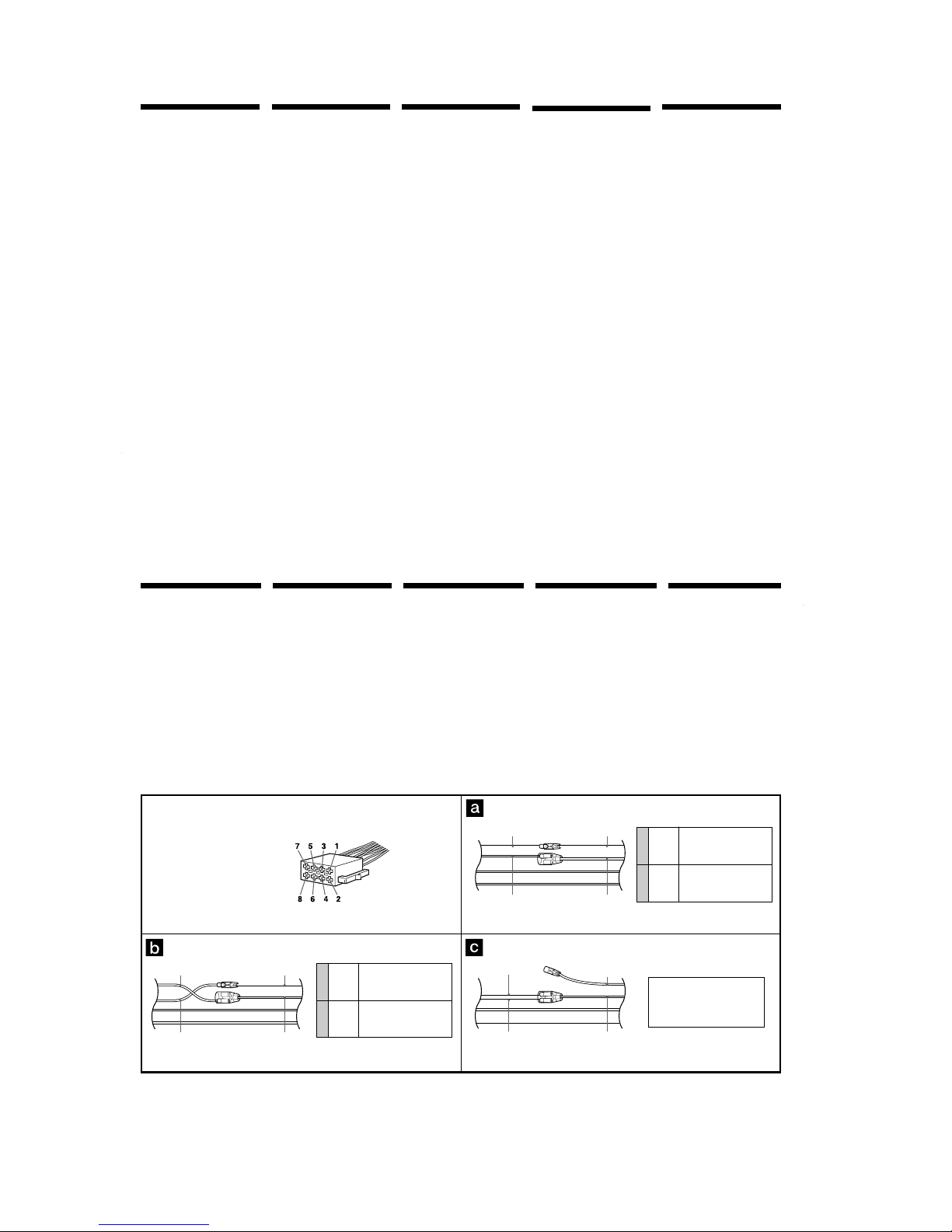
Auxiliary power connector
Conector de alimentación auxiliar
Yttre strömanslutning
Conector de corrente auxiliar
Υποδοχή βοηθητικής τροφοδοσίας
4
7
Yellow
Amarillo
Gul
Amarelo
Κίτρινο
Red
Rojo
Röd
Vermelho
Κκκινο
continuous power supply
suministro de alimentación continua
kontinuerlig strömförsörjning
alimentação de corrente contínua
συνεχής τροφοδοσία
switched power supply
suministro conmutado de alimentación
switchad strömförsörjning
alimentação de corrente comutada
διακοπτµενη τροφοδοσία
the car without ACC position
automóvil sin posición ACC
bil utan ACC-läge
o carro sem posição ACC
αυτοκίνητο χωρίς θέση ACC
4
7
Yellow
Amarillo
Gul
Amarelo
Κίτρινο
Red
Rojo
Röd
Vermelho
Κκκινο
switched power supply
suministro conmutado de alimentación
switchad strömförsörjning
alimentação de corrente comutada
διακοπτµενη τροφοδοσία
continuous power supply
suministro de alimentación continua
kontinuerlig strömförsörjning
alimentação de corrente contínua
συνεχής τροφοδοσία
Red
Rojo
Röd
Vermelho
Κκκινο
Yellow
Amarillo
Gul
Amarelo
Κίτρινο
Yellow
Amarillo
Gul
Amarelo
Κίτρινο
Red
Rojo
Röd
Vermelho
Κκκινο
Red
Rojo
Röd
Vermelho
Κκκινο
Red
Rojo
Röd
Vermelho
Κκκινο
Red
Rojo
Röd
Vermelho
Κκκινο
Yellow
Amarillo
Gul
Amarelo
Κίτρινο
Yellow
Amarillo
Gul
Amarelo
Κίτρινο
Yellow
Amarillo
Gul
Amarelo
Κίτρινο
Yellow
Amarillo
Gul
Amarelo
Κίτρινο
Red
Rojo
Röd
Vermelho
Κκκινο
8
XR-M510
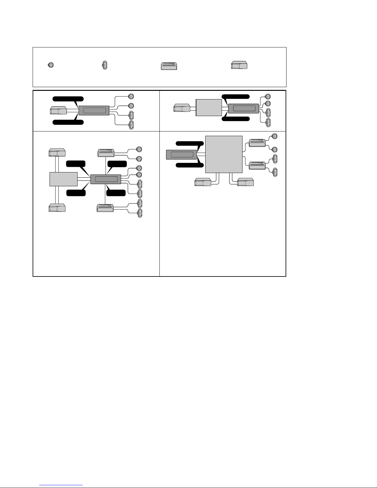
CD/MD changer
Cambiador de CD/M D
CD/MD-skivväxlare
Permutador CD/MD
CD/MD changer
Power amplifier
Amplificador de potencia
Effektförstärkare
Amplificador de potência
Τελικς ενισχυτής
Front speaker
Altavoz delantero
Främre högtalare
Altifalante diant eiro
Εµπρς ηχείο
Rear speaker
Altavoz trasero
Bakre högtalare
Altifalante t raseiro
Πίσω ηχείο
Equipo utilizado en las
ilustraciones (no suministrado)
Utrustning som visas i
illustrationer (medföljer inte)
Equipamento utilizado nas
ilustrações (não fornecido)
∆ιάγραµµα συνδέσεων
Χρησιµοποιούµενος εξοπλισµς σε
εικνες (δεν παρέχεται)
AB
BUS
AUDIO IN
AUDIO
OUT FRONT
BUS
CONTROL IN
AUDIO OUT
REAR
BUS CONTROL IN
BUS AUDIO IN
BUS AUDIO IN
BUS CONTROL IN
C
BUS CONTROL IN
AUDIO OUT REAR
Digital equalizer pre-amplifier
Preamplificador ecualizador
digital
Digital förförstärkare med
equaliser
Pré-amplificador equalizador
digital
Ψηφιακς ισοσταθµιστής
προενισχυτής
XDP-210EQ*, XDP-4000X
*
D
DAB tuner unit
Sintonizador DAB
DAB-tunerenhet
Sintonizador DAB
Συσκευή δέκτη DAB
XT-100DAB*
Source selector*
Selector de fuente*
Väljare för ljudkälla*
Selector de fonte*
Επιλογέας πηγής*
For connecti ng two or more CD/MD
changers, th e source selector XA-C30
(opt ional) is necessary.
Si desea conectar dos o más cambiadores,
necesitará el selecto r de fuente XA-C30
(opcion al).
För anslutn ing av t vå eller f lera växlar e
krävs väljarn a XA-C30 (tillval).
Para ligar u m ou mais permut adores, é
necessário o selector de f onte XA-C30
(opcion al).
Για τη σύνδεση δύο ή περισσοτέρων CD/
MD changer, απαιτείται επιλογέασ πηγήσ
XA-C30 (προαιρετικσ).
When connecting a digital equalizer pre-amplifier
(XDP-210EQ, XDP-4000X)
• Use an opt ional exterio r amplifier . The built-in
ampli fier of t his unit can not be used in t his case. For
detai ls, refer t o th e Installat ion/Connections manu al
XDP-210EQ, XDP-4000X.
• For det ails about the con nection, refer to t he
Instllat ion/Connections manual XDP-210EQ, XDP4000X. (not supplied)
Si conecta un preamplificador ecualizador digital
(XDP-210EQ, XDP-4000X.)
• Utilice un amplif icador o pcional externo . El
ampli ficador incorporado d e esta unidad no pu ede
uti lizarse en este caso. Para más información, consult e
el manu al de instalación/conexiones de la uni dad XDP210EQ, XDP-4000X.
• Para obt ener inform ación det allada sobr e la conexión,
consulte el manual de instalación/conexion es de la
unid ad XDP-210EQ, XDP-4000X. (no suministrada)
När du ansluter en digital förförstärkare med equaliser
(XDP-210EQ, XDP-4000X.)
• Använd en valf ri ext ern f örstärkare. Den inb yggda
för stärkaren kan int e användas i det ta f all. M er
inf ormat ion f inns i M ontering/A nslutninghandboken
XDP-210EQ, XDP-4000X.
• Mer inf ormat ion o m hur du anslut er utrustning fin ns i
Mon tering/Anslut ning handboken
XDP-210EQ, XDP-4000X. (medföl jer inte)
Se ligar um pré-amplificador equalizador digital
(XDP-210EQ, XDP-4000X.)
• Utilize um amplificador exterior opcio nal. O
ampli ficador int egrado n este aparelho não po de
ser util izado neste caso. Para obter mais
inf ormações, consulte o manual de Instalação/
Ligações XDP-210EQ, XDP-4000X.
• Para obt er mais inf ormações sobre a li gação,
consulte o manual de Instalação/ Ligações do
XDP-210EQ, XDP-4000X. (não for necido)
ταν συνδέετε έναν ψηφιακ ισοσταθµιστή
προενισχυτή (XDP-210EQ, XDP-4000X)
• Χρησιµοποιείτε έναν προαιρετικ εξωτερικ
ενισχυτή. Σε αυτή την περίπτωση δεν µπορεί να
χρησιµοποιηθεί ο ενσωµατωµένοσ ενισχυτήσ
αυτήσ τησ συσκευήσ. Για περισστερεσ
λεπτοµέρειεσ, δείτε το εγχειρίδιο
Εγκατάστασησ/Συνδέσεων XDP-210EQ,
XDP-4000X
• Για περισστερεσ λεπτοµέρειεσ σχετικά µε τη
σύνδεση, δείτε το εγχειρίδιο Εγκατάστασησ/
Συνδέσεων XDP-210EQ, XDP-4000X (δεν
παρέχεται)
Note
Be sure to conn ect the earth cord befo re
connecti ng the amplifier.
Nota
Asegúrese de conectar primero el cable de puesta a
masa antes de reali zar la conexión al amp lifi cador.
Obsevera
Var nog a med att först ansluta j orden, innan d u
ansluter förstärkaren.
Nota
Ant es de fazer a ligação ao amplificado r tem de ligar
prim eiro o cabo de ligação à massa.
Σηµείωση
Βεβαιωθείτε τι συνδέσατε πρώτα ένα καλώδιο
γείωσησ, πριν συνδέσετε τον ενισχυτή.
* not suppli ed
no sumin istrado
medf öljer inte
não f ornecido
δεν παρέχεται
* not suppli ed
no sumin istrado
medf öljer inte
não f ornecido
δεν παρέχεται
* not suppli ed
no sumin istrado
medf öljer inte
não f ornecido
δεν παρέχεται
Connection diagram Diagrama de conexiones
Kopplingsschema
Diagrama de ligações
Equipment used in illustrations
(not supplied)
9
XR-M510
Exemplo de ligações
*1Nota referente à ligação da antena
Se a antena do au tomóvel for uma
anten a de tipo ISO (Internat ional
Organi zation for Stand ardizat ion), u tilize
o adapt ador fornecido 6 para f azer a
ligação r espectiva.
Ligue pr imeiro a antena do aut omóvel ao
adapt ador f ornecido e depoi s à ficha tipo
jack de ant ena do sistema principal .
*2Cabo de terminais RCA (não fornecido)
Anslutningarna enligt
exemplet
*1Angående antennanslutning
Om mot orantennen är av ISO-typ
(Inter national Organizati on for
Standardi zation), använder du
medf öljande adapter 6 för att ansluta
den.
Anslut först motoranten nen till
medf öljande adapter och däref ter till
anten nuttaget på huvud enheten.
*
2
Kabel med RCA-kontakter (medföljer
inte)
Ejemplo de conexiones
*1Nota sobre la conexión de la antena
Si la antena d el automóvil es del tipo ISO
(Inter national Organizati on for
Standardi zation), emplee el adaptad or
suministr ado 6 para con ectarla.
En primer lugar, conecte la ant ena del
auto móvil al adaptador sumin istrado y, a
conti nuación, a la toma de anten a de la
unid ad principal.
*2Cable con clavijas RCA (no suministrado)
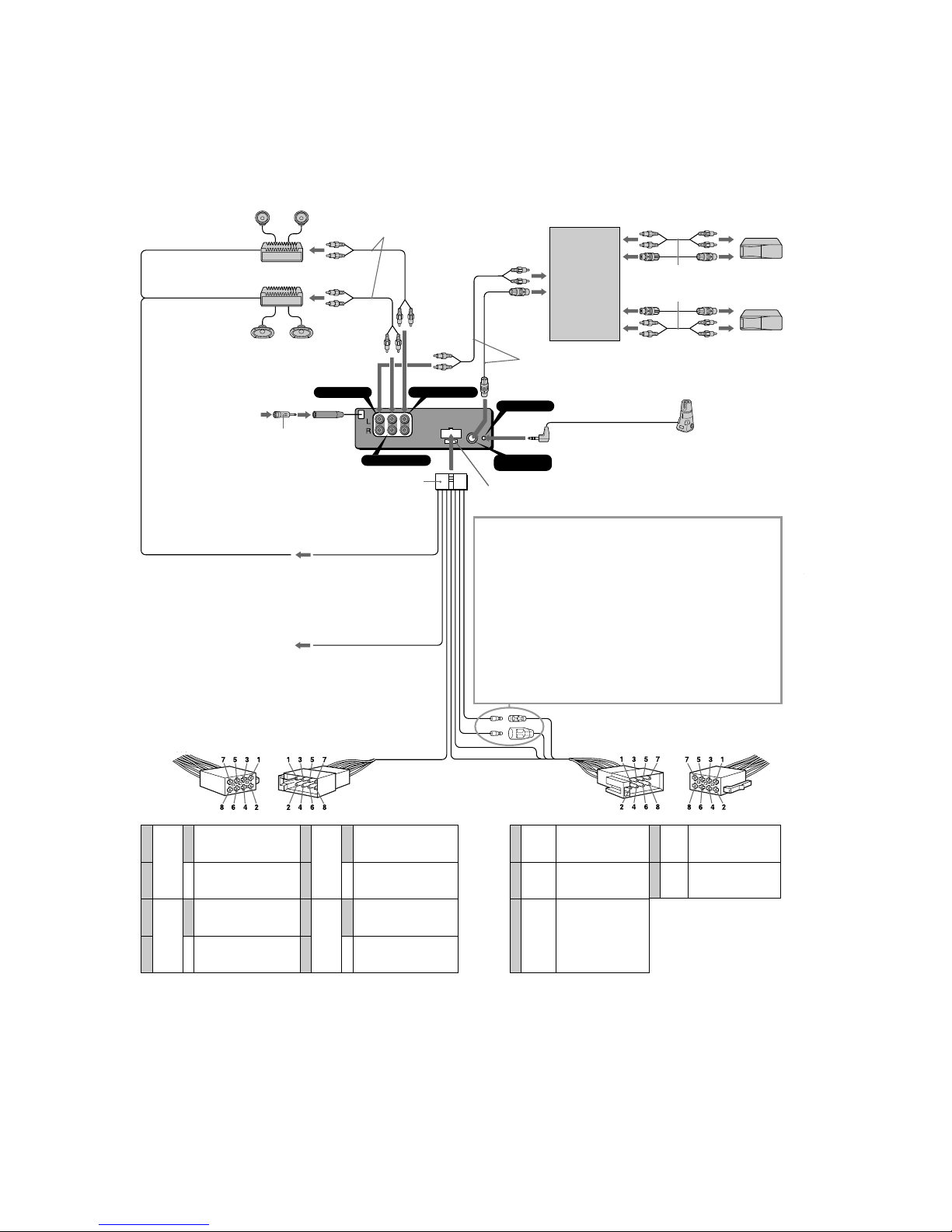
Connection example
*1Note for the aerial connecting
If you r car aerial is an ISO (Inter natio nal
Organi sation f or Standardisation ) type,
use the suppl ied adaptor 6 t o connect it.
First connect t he car aerial to t he
supplied adaptor, then connect i t to the
aerial j ack of t he master u nit.
*2RCA pin cord (not supplied)
Παράδειγµα σύνδεσης
*1Σηµείωση σχετικά µε τη σύνδεση τησ
κεραίασ
Αν η κεραία του αυτοκινήτου σασ είναι
τύπου ISO (εγκεκριµένη απ το ∆ιεθνή
Οργανισµ Τυποποίησησ),
χρησιµοποιήστε τον παρεχµενο
προσαρµογέα 6 για να τη συνδέσετε.
Συνδέστε την κεραία του αυτοκινήτου
πρώτα στον παρεχµενο προσαρµογέα,
και στη συνέχεια στην υποδοχή κεραίασ
τησ κυρίωσ συσκευήσ.
*2Καλώδιο βύσµατοσ RCA (δεν παρέχεται)
6
AM P REM
BUS AUDIO IN
AUDIO OUT FRONT
BUS CONTROL IN
AUDIO OUT REAR
REMOTE IN
8
ATT
Max. supply current 0.3 A
Corriente máx. de alimentación de 0,3 A
Maximal strömtillförsel 0,3 A
Corrente máxima de 0,3 A
Μέγιστο ρεύµα τροφοδοσίας 0,3 A
to the interf ace cable of a car telephone
al cable de interfaz de un teléfono para automóvil
till mobiltelefonens gränssnittskabel
Ao cabo de interface de um telefone para automóvel
προς το καλώδιο διασύνδεσης ενς τηλεφώνου
αυτοκινήτου
to a car’s speaker connector
a un conector de altavoces del automóvil
till bilens högtalaranslutning
ao conector de um altifalant e do automóvel
προς την υποδοχή ηχείου του αυτοκινήτου
Light blue
Azul celeste
Ljusblå
Azul claro
Ανοικτ µπλε
Blue/white striped
Con raya azul/blanca
Blå/vit-randig
Azul com listras brancas
Μπλε/λευκ µε ρίγες
from car aerial*
1
de la antena del automóvil*
1
från bilantenn*
1
da antena do automóvel*
1
απ την κεραία του αυτοκινήτου*
1
Source selector
(not supplied)
Selector de fuente
(no suministrado)
Väljare för ljudkälla
(medföljer inte)
Selector de fonte
(não fornecido)
Επιλογέας πηγής
(δεν παρέχεται)
XA-C30
Supplied to XA-C30
Suministrado con el XA-C30
Medföljer XA-C30
Fornecido para o XA-C30
Παρέχονται µε το XA-C30
Rotary commander RM-X4S (not supplied)
Mando rotat ivo RM-X4S (no suministrado)
Vridkontroll RM-X4S (medföljer inte)
Comando rotativo RM-X4S (não fornecido)
Περιστροφικ χειριστήριο RM-X4S (δεν παρέχεται)
*
2
*
2
Fuse (10 A)
Fusible (10 A)
Säkring (10 A)
Fusivel (10 A)
Ασφάλεια (10 A)
to a car’s auxiliary power connector
a un conector de alimentación auxiliar del automóvil
till bilens yttre strömanslutning.
a um conector de alimentação auxiliar do automóvel
προς την υποδοχή βοηθητικής τροφοδοσίας του αυτοκινήτου
Insert with the cord upwards.
Insertar con el cable hacia arriba.
Sätt in med kabeln vänd uppåt.
Inserir com o fio virado para cima.
Εισάγετε µε το καλώδιο προς τα επάνω
WARNING
Auxiliary power connectors may vary depending on
the car. Be sure to check the power connection
diagram. Improper connections may damage your
car. If the supplied power connecting cord can not be
used with your car, consult your nearest Sony dealer.
ADVERTENCIA
Los conectores de alimentación auxiliar pueden
variar en f
unción del automóvil. Asegúrese de
consultar el diagrama de conexión de alimentación.
Las conexiones incorrectas pueden dañar el
automóvil. Si no es posible utilizar con el automóvil
el cable de conexión de alimentación suministrado,
póngase en contacto con el proveedor Sony más
próximo.
VARNING
Typen av yttre strömanslutning varierar från bil till
bil. K
ontrollera strömanslutningsschemat som
medföljer enheten så att du ansluter på rätt sätt.
Felaktig anslutning kan skada bilen. Kontakta
närmaste Sony-återförsäljare om den medföljande
strömkabeln inte passar till din bil.
ADVERTÊNCIA
Os conectores de corrente auxiliares podem variar de
c
arro para carro. Não se esqueça de verificar o
diagrama de ligação de corrente fornecido com o
aparelho. As ligações mal executadas podem
danificar o seu carro. Se não puder utilizar o cabo de
alimentação fornecido no seu carro, contacte o
agente Sony da sua zona.
ΠΡΟΕΙ∆ΟΠΟΙΗΣΗ
Οι βοηθητικές υποδοχές τροφοδοσίας µπορεί να
διαφέρουν ανάλογα µε το αυτοκίνητο. Ελέγξτε το
διάγραµµα σύνδεσης της τροφοδοσίας.
Λανθασµένες συνδέσεις µπορεί να προκαλέσουν
ζηµιά στο αυτοκίνητ σας. Αν το παρεχµενο
καλώδιο τροφοδοσίας δεν µπορεί να
χρησιµοποιηθεί στο αυτοκίνητ σας,
συµβουλευθείτε τον πλησιέστερο αντιπρσωπο της
Sony.
Supplied to the CD/MD changer
Suministrado con el cambiador de CD/MD
Medföljer CD/M D-växlaren
Fornecido para o permutador de CD/MD
Παρέχονται µε το CD/MD changer
Yellow
Amarillo
Gul
Amarelo
Κίτρινο
Blue
Azul
Blå
Azul
Μπλε
Orange/
White
Naranja/
blanco
Orange/vit
Cor de
laranja/
branco
Πορτοκαλί/
Λευκ
continuous power supply
suministro de alimentación continua
kontinuerlig strömförsörjning
alimentação de corrente contínua
συνεχής τροφοδοσία
power aerial control
control de antena motorizada
styrning av motorantenn
antena eléctrica
έλεγχος ηλεκτρικής κεραίας
switched illumination power
supply
fuente de alimentación de
iluminación conmutada
Switchad strömförsörjning till
belysning
fonte de alimentação comutada
para iluminação
διακοπτµενη τροφοδοσία
φωτεινής ένδειξης
1
2
3
4
Speaker, Rear, Right
Altavoz, parte posterior, derecho
Högtalare, bakre, höger
Altifalante, Parte de trás, Direito
Ηχείο, Πίσω, ∆εξί
Speaker, Rear, Right
Altavoz, parte posterior, derecho
Högtalare, bakre, höger
Altifalante, Parte de trás, Direito
Ηχείο, Πίσω, ∆εξί
Speaker, Front, Right
Altavoz, parte front al, derecho
Högtalare, främre, höger
Altifalante, Parte da frent e, Direito
Ηχείο, Εµπρς, ∆εξί
Speaker, Front, Right
Altavoz, parte front al, derecho
Högtalare, främre, höger
Altifalante, Parte da frent e, Direito
Ηχείο, Εµπρς, ∆εξί
5
6
7
8
Speaker, Front, Left
Altavoz, parte front al, izquierdo
Högtalare, främre, vänster
Altifalante, Parte da frent e, Esquerdo
Ηχείο, Εµπρς, Αριστερ
Speaker, Front, Left
Altavoz, parte front al, izquierdo
Högtalare, främre, vänster
Altifalante, Parte da frent e, Esquerdo
Ηχείο, Εµπρς, Αριστερ
Speaker, Rear, Left
Altavoz, parte posterior, izquierdo
Högtalare, bakre, vänster
Altifalante, Parte de trás, Esquerdo
Ηχείο, Πίσω, Αριστερ
Speaker, Rear, Left
Altavoz, parte posterior, izquierdo
Högtalare, bakre, vänster
Altifalante, Parte de trás, Esquerdo
Ηχείο, Πίσω, Αριστερ
Purple
Púrpura
Violett
Violeta
Μωβ
Negati ve polarity positions 2, 4, 6, and 8 h ave striped cords.
Las posiciones de polari dad negativa 2, 4, 6 y 8 tienen cables con raya.
De negat iva polpositionerna 2, 4, 6 och 8 h ar randiga kabl ar.
As posições 2, 4, 6 e 8 (polarid ade negat iva) têm cabos às riscas.
Οι θέσεισ αρνητικήσ πολικτητασ 2, 4, 6, και 8 έχουν καλώδια µε ρίγεσ.
Green
Verde
Grön
Verde
Πράσινο
White
Blanco
Vit
Branco
Λευκ
Grey
Gris
Grå
Cinzento
Γκρι
+
–
+
–
+
–
+
–
7
8
4
5
6
Red
Rojo
Röd
Vermelho
Κκκινο
Black
Negro
Svart
Preto
Μαύρο
switched power supply
suministro conmutado de alimentación
switchad strömförsörjning
alimentação de corrente comutada
διακοπτµενη τροφοδοσία
earth
toma de tierra
jord
Terra
γη
Positions 1, 2 and 3 d o not have pins.
Las posiciones 1, 2 y 3 no disponen de
term inales.
Positioner na 1, 2 och 3 saknar stift.
As posições 1, 2 e 3 não têm t erminais.
Οι θέσεισ 1, 2 και 3 δεν έχουν pin.
10
XR-M510
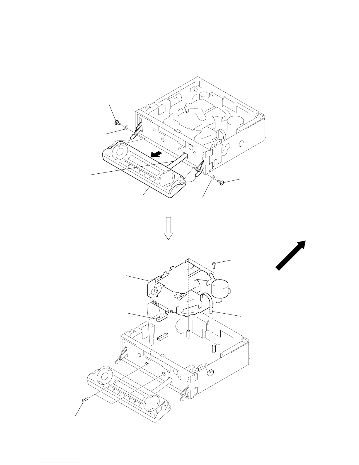
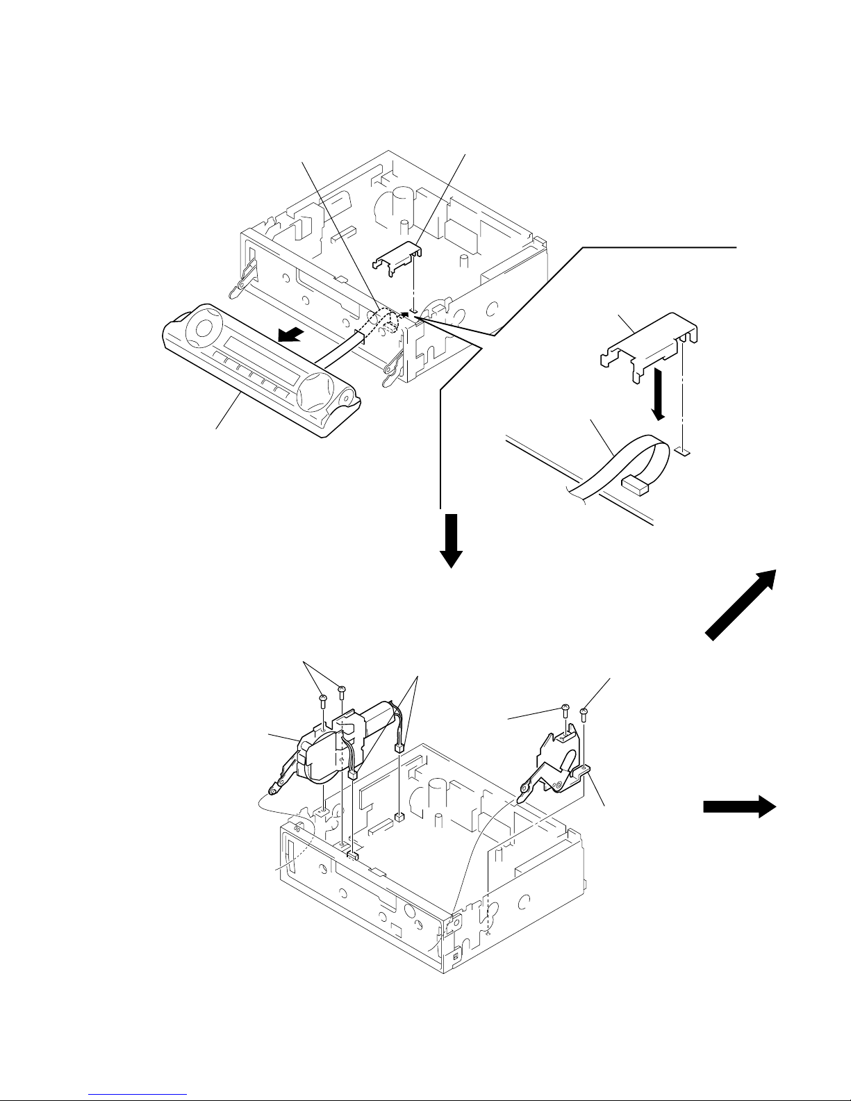
SECTION 3
DISASSEMBLY
• See page 3 for Servicing Notes.
Note: Follow the disassembly procedure in the numerical order given.
MECHANISM DECK (MG-25E-136)
3
front panel assy
flexible board
Note: Don't pull out flexible board
from front panel assy.
1
screw (panel)
2
spacer (arm)
1
screw (panel)
2
spacer (arm)
5
two screws
(PTT2.6
×
6)
5
two screws
(PTT2.6
×
6)
4
flexible board
(CN401)
4
connector
(CN400)
6
mechanism deck
(MG-25E-136)
11
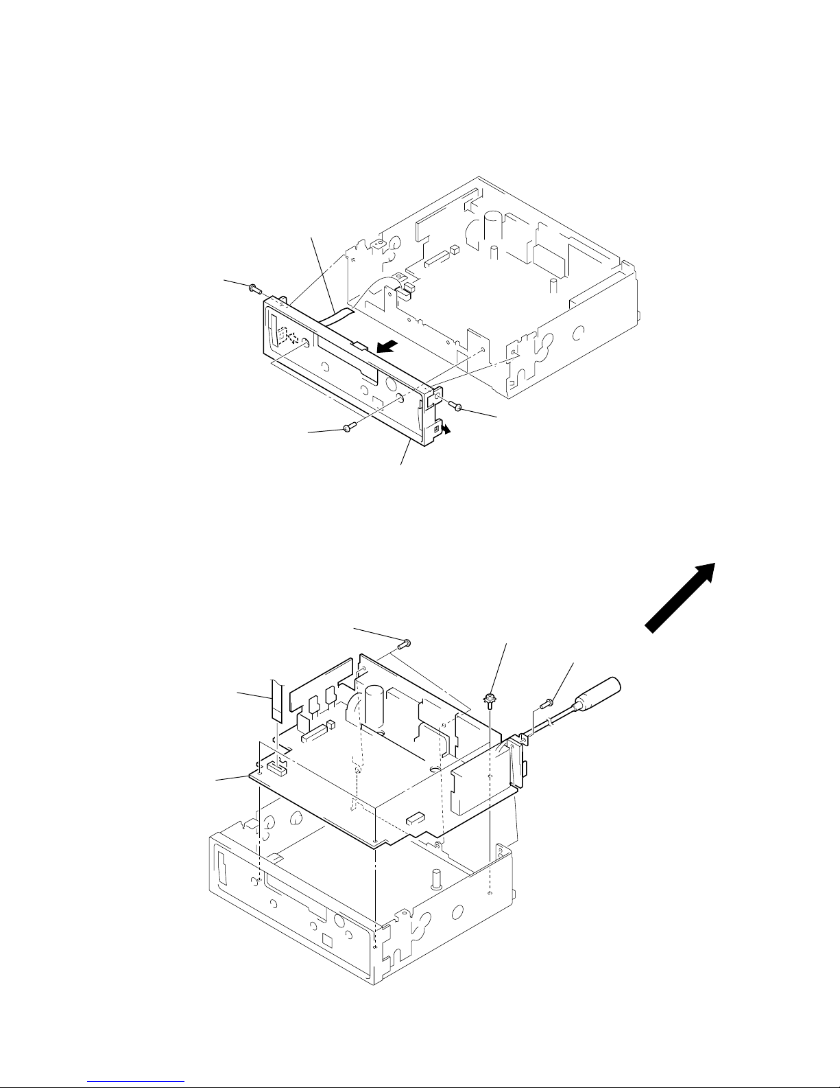
XR-M510
1
cover (flexible)
2
flexible board
(CN402)
2
flexible cover
•
Note for Installation of Flexible Board
1
Set the flexible board to
be at the position in the figure.
3
front panel assy
FRONT PANEL ASSY
MOTOR BLOCK ASSY, CAM (R) ASSY
4
screw
(PTT2.6
×
6)
4
screw
(PTT2.6
×
6)
3
motor block assy
2
two screws
(PTT2.6
×
6)
5
cam (R) assy
1
two connectors
(CN501, CN602)
12
XR-M510
SUB PANEL (XR) SUB ASSY
MAIN BOARD
2
screw
(PTT2.6
×
6)
2
two screws
(PTT2.6
×
6)
2
screw
(PTT2.6
×
6)
1
flexible board
(CN601)
3
sub panel (XR) sub assy
2
two screws
(PTT2.6
×
8)
3
three ground point screws
(PTT2.6
×
6)
1
flexible board
(CN601)
2
screw
(PTT2.6
×
8)
4
main board
13
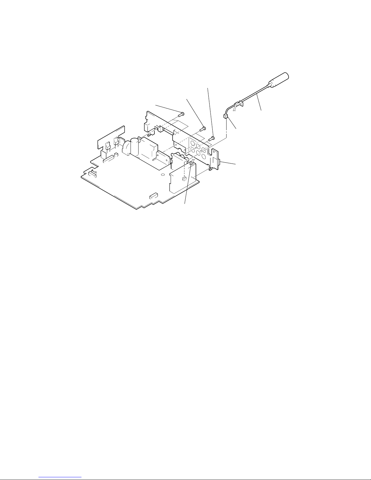
XR-M510
HEA
T SINK
4
three screws
(PTT2.6
×
8)
4
two screws
(PTT2.6
×
8)
2
connector
(CN100)
3
cord (with connector) (ANT)
6
heat sink
1
Remove solder of
cord (with connector) (ANT).
5
two screws
(PTT2.6
×
12)

14
XR-M510
SECTION 4
ASSEMBLY
Note: Follow the assembly procedure in the numerical order given.
4-1. FRONT PANEL MACHINERY
MOTOR BLOCK ASSY
CAM (R) ASSY
8
two screws
(PTT2.6
×
6)
9
screw (BTT)
1
cam (L)
6
washer (M)
5
gear (C)
6
washer (M)
6
washer (M)
4
gear (B)
3
gear (A)
7
bracket (motor) assy
Set bracket (motor) assy
to be at the position in the
figure.
switch
concave portion
hole
2
stop ring 1.5
Note: When installing cam (L), adjust the hole and concave portion.
1
cam (R)
concave portion
hole
2
stop ring 1.5
Note: When installing cam (R), adjust the hole and concave portion.
15
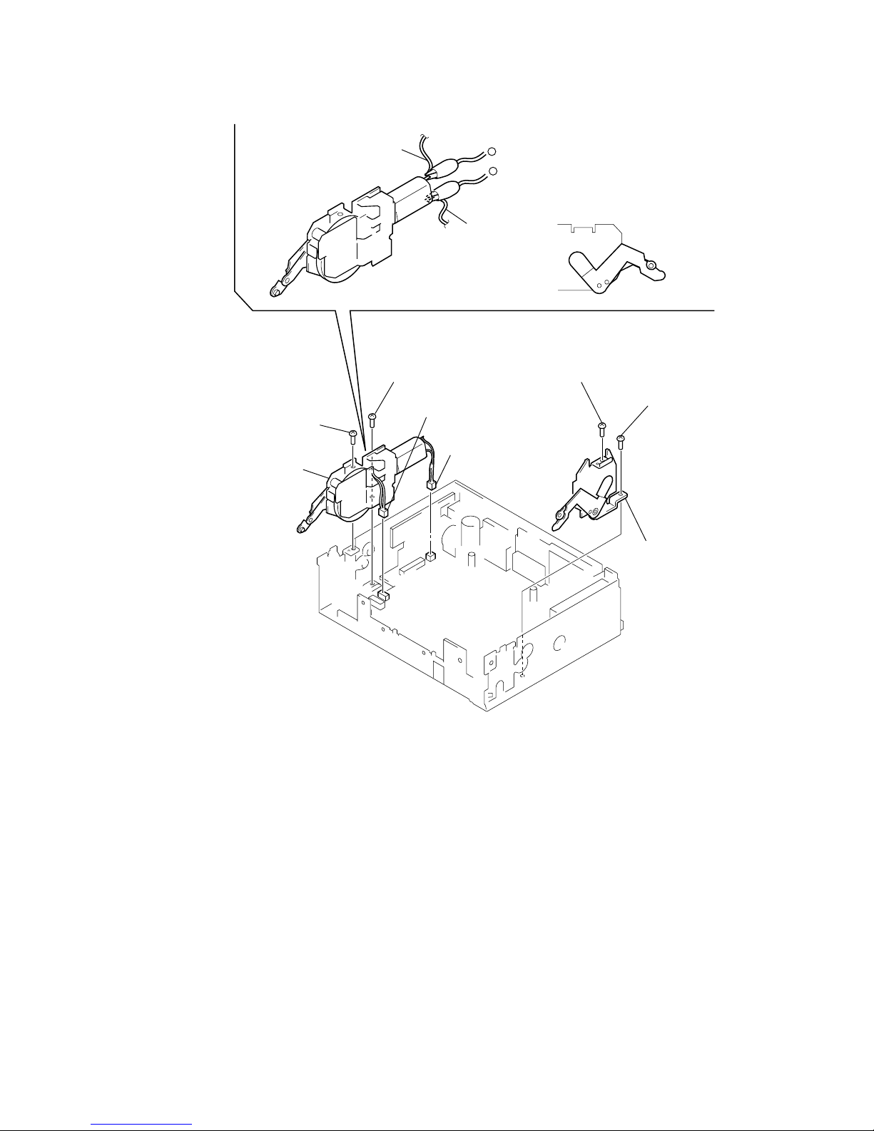
XR-M510
MO
TOR BLOCK ASSY, CAM (R) ASSY
4
screw
(PTT2.6
×
6)
7
screw
(PTT2.6
×
6)
3
motor block assy
4
screw
(PTT2.6
×
6)
6
cam (R) assy
5
connector
(CN602)
5
connector
(CN501)
black wiring
yellow wiring
1
Supply the power to the motor.
Voltage : 9V
Yellow wiring : MOTOR –
Black wiring : MOTOR +
2
Motor stops at full open position.
full open position
–
+
7
screw
(PTT2.6
×
6)
16
XR-M510
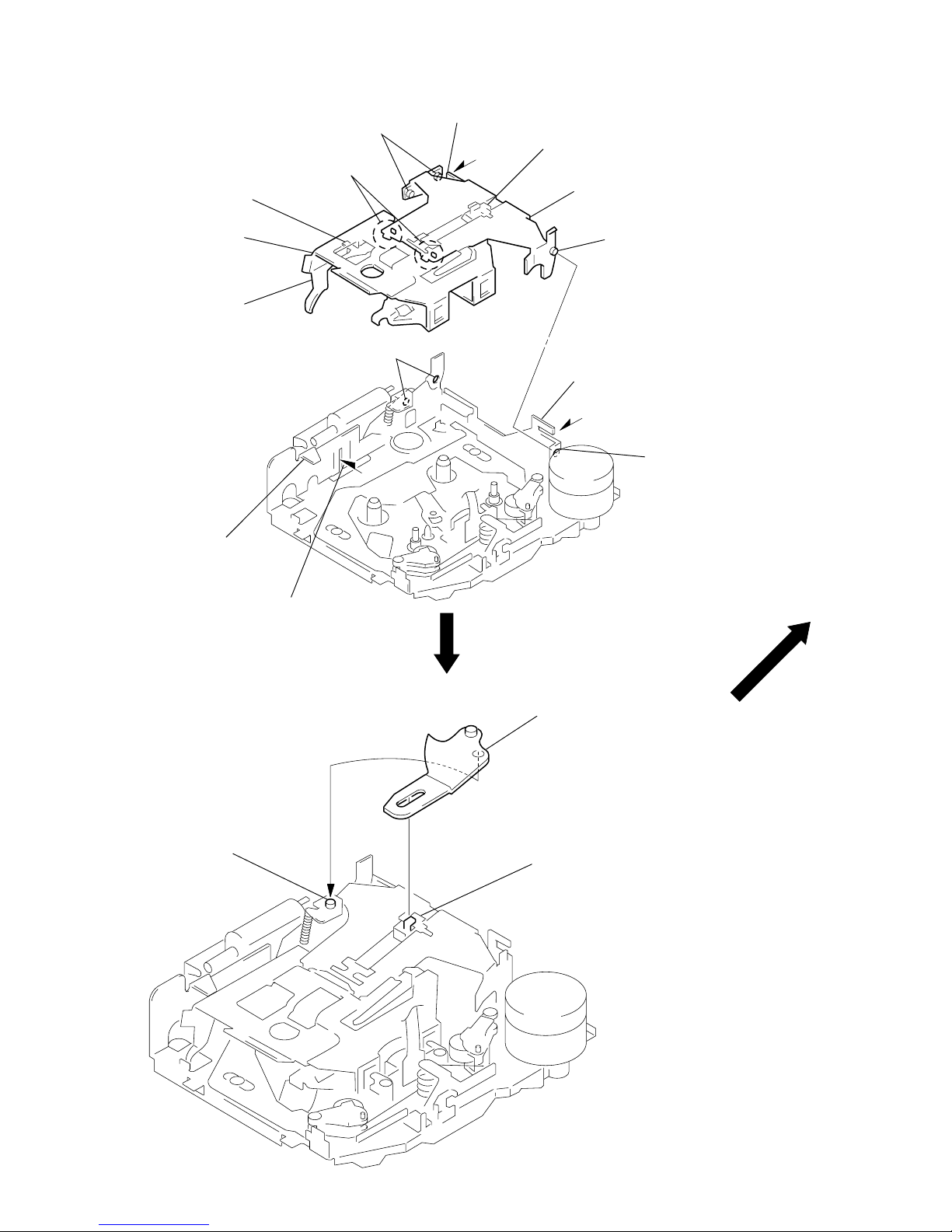
4-2. MECHANISM DECK
HOUSING
ARM (SUCTION)
A
part
C
part
B
part
D
part
8
Hold the hanger by
bending the claw.
6
Fit projection on D part.
4
Fit claw on B part.
3
Put the housing
under
A
part.
5
Fit projection on C part.
1
Install the catch to the hanger.
2
Install the hanger onto
two claws of the housing.
7
Holder the hanger by bending the claw.
hanger
housing
2
Move the arm (suction) in the arrow
direction and fit on projection.
1
Fit the arm (suction) on the shaft.
projection
17
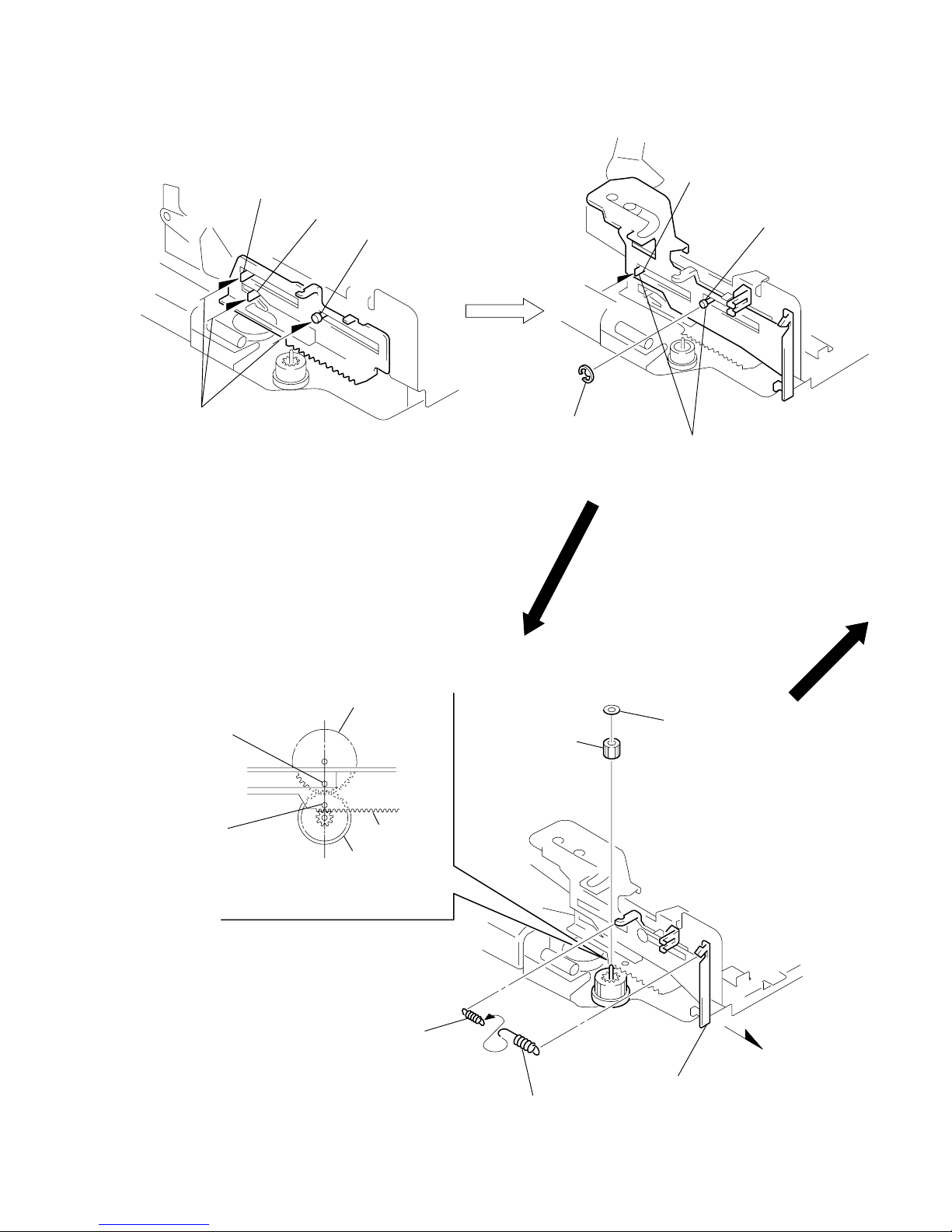
XR-M510
shaft
A
shaft
B
shaft
C
1
Fit the lever (LDG-A) on
shafts
A
– C and install it.
shaft
A
shaft
B
2
Fit the lever (LDG-B) on
shafts
A
and B and
install it.
3
type-E stop ring 2.0
LEVER (LDG-A) / (LDG-B)
GEAR (LDG-FT)
gear (LDG-D)
5
gear (LDG-FT)
6
polyethylene washer
2
tension spring (LD-2)
2
tension spring (LD-1)
gear (LDG-FB)
lever (LDG-A)
hole
hole
4
Align hole in the gear (LDG-D)
with hole the lever (LDG-A).
3
Move the lever (LDG-B)
in the arrow direction.
1
18
XR-M510
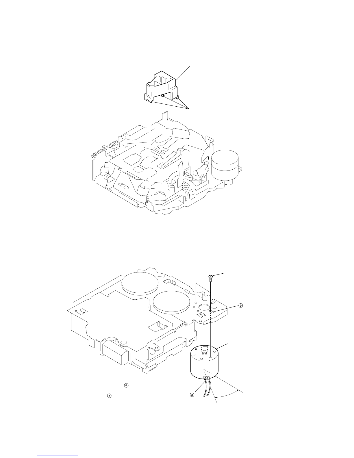
GUIDE (C)
MOUNTING POSITION OF CAPSTAN/REEL MOTOR (M901)
2
guide (C)
1
three claws
two precision screws
(P2
×
2)
Note: Mount the motor so that the
angle between of the
motor and the hole for the
screw becomes 30
°
as
shown in this figure.
capstan/reel motor
(M901)
30˚
 Loading...