

Page 1

OPTICAL FIBER CAMERA ADAPTER
CA-F101
電気製品は、安全のための注意事項を守らないと、
火災や人身事故になることがあります。
このオペレーションマニュアルには、事故を防ぐための重要な注意事項と
製品の取り扱いかたを示してあります。このオペレーションマニュアルを
よくお読みのうえ、製品を安全にお使いください。お読みになったあとは、
いつでも見られるところに必ず保管してください。
OPERATION MANUAL [Japanese/English]
1st Edition
Page 2
日本語
安全のために
ソニー製品は安全に充分配慮して設計されています。しかし、電気製品はまちがっ
た使い方をすると、火災や感電などにより死亡や大けがなど人身事故につながるこ
とがあり、危険です。
事故を防ぐために次のことを必ずお守りください。
安全のための注意事項を守る
4 ページの注意事項をよくお読みください。
定期点検を実施する
長期間安全に使用していただくために、定期点検を実施することをおすすめしま
す。点検の内容や費用については、ソニーのサービス担当者または営業担当者にご
相談ください。
故障したら使用を中止する
ソニーのサービス担当者、または営業担当者にご連絡ください。
万一、異常が起きたら
• 異常な音、におい、煙が出たら
• 落下させたら
警告表示の意味
オペレーションマニュアルおよび
製品では、次のような表示をして
います。表示の内容をよく理解し
てから本文をお読みください。
この表示の注意事項を守らないと、
感電やその他の事故によりけがを
したり周辺の物品に損害を与えた
りすることがあります。
注意を促す記号
行為を禁止する記号
m
a 電源を切る。
b 接続ケーブルや電源コードを抜く。
c ソニーのサービス担当者、または営業担当者に修理を依頼する。
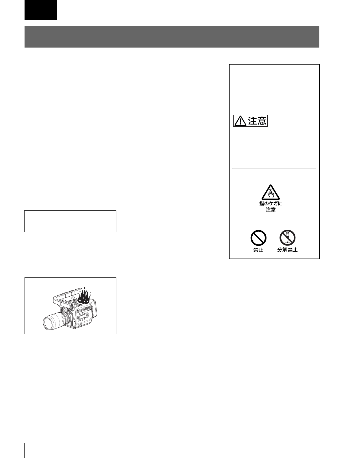
炎が出たら
m
すぐに電源を切り、消火する。
2
安全のために
Page 3
目次
注意 .................................................................................................................................. 4
その他の安全上のご注意 ........................................................................................................ 4
概要......................................................................................................................................... 5
基本運用システム........................................................................................................ 5
各部の名称と働き ................................................................................................................... 7
取り付け.................................................................................................................................. 8
本機をカメラに取り付けるには .................................................................................. 8
ビューファインダーを本機に取り付けるには........................................................... 10
本機にセンターハンドル(カメラに付属)を取り付けるには ................................. 10
レコーダーの接続と設定 ...................................................................................................... 10
接続............................................................................................................................ 10
レコーダー側の設定 .................................................................................................. 10
電源....................................................................................................................................... 11
カメラ電源の接続と操作 ........................................................................................... 11
本機への電源の接続 .................................................................................................. 11
動作の確認 ............................................................................................................................ 12
JP
保守....................................................................................................................................... 13
光ファイバーコネクターの取り扱い ......................................................................... 13
コネクターのクリーニング........................................................................................ 13
仕様....................................................................................................................................... 15
目次
3
Page 4
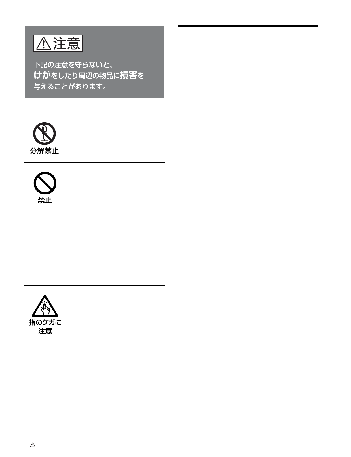
分解しない、改造しない
分解したり、改造したりすると、感電の
原因となります。
接続ケーブルやDC 電源コード
を傷つけない
接続ケーブルや DC 電源コードを傷つけ
ると、火災や感電の原因となります。
• ケーブルを加工したり、傷つけたりし
ない。
• 重いものをのせたり、引っ張ったりし
ない。
• 熱器具に近づけたり、加熱したりしな
い。
• ケーブルを抜くときは、必ずプラグを
持って抜く。
万一、ケーブルが傷んだら、ソニーの
サービス担当者に交換をご依頼ください。
その他の安全上のご注意
本機は「クラス1レーザー製品」です。
レーザー機器についてのご注意
ここに規定した以外の手順による制御および調整は、危険な
レーザー放射の被爆をもたらします。
回転コネクターは慎重に扱う
回転コネクターを乱暴に扱うと、コネク
ター部が回転して指を挟むことがありま
す。ケーブルの接続および取り外しは無
理な力をかけずに慎重に行ってください。
4
注意 / その他の安全上のご注意
Page 5
概要
オプティカルファイバーカメラアダプター CA-F101 は、ソ
ニーデジタルシネマカメラ F23 または F35 にダイレクトに
装着し、HD ポータブルデジタルレコーダー SRW-1/HD ビ
ベースステーション側であるレコーダーにカメラのリモート
コントロールユニットを接続し、SelectFPS 機能をはじめ
様々なカメラコントロールも可能です。
デオプロセッサー SRPC-1 との間の信号伝送とインター
フェースを、光複合カメラケーブルを介して実現するカメラ
アダプターです。
RGB4:4:41080/30P もしくは YCbCr4:2:21080/60P までの
ビデオ信号、2 チャンネルのオーディオ信号、およびコント
ロール信号を、1 本の光複合カメラケーブルで伝送します
(最長 1km)。
F23/F35 とレコーダーを分離して運用するとき、カメラと
レコーダー間のケーブル本数を削減できるため、システム運
用が容易になります。
ご注意
CA-F101 を使用するときは、組み合わせる機器が次の条件
に合っているかどうかを、あらかじめ確認してください。
• HD ビデオプロセッサー SRPC-1 にオプティカルインター
フェースユニット HKSR-101 が装着されていること。
• デジタルシネマカメラ F23/F35が Ver.1.3以降であること。
• SRW-1 および SRPC-1 が Ver.2.6 以降であること。
• SelectFPS 機能を使用する場合は、SRW-1 にピクチャー
キャッシュボード HKSR-102 が装着されていること。
基本運用システム
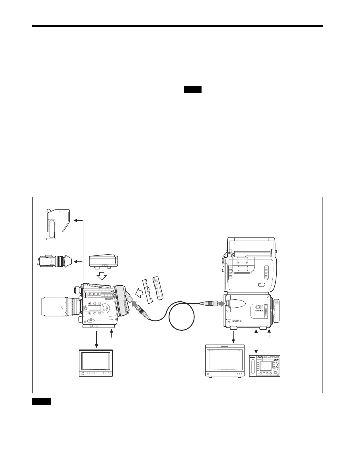
本機は、主に下記のようなシステムでの運用を想定して設計されています。
ビューファインダー
a)ARIB(BTAS-1005B)、ANSI/SMPTE(304M-1998/311M-1998)、EBU(R100-
1999) 準拠品
b)RM-B750 はカメラ側の RM コネクターに接続することも可能です。ただし、
カメラとレコーダーに同時に接続して使用することはできません。RM-B750
の LCD 画面でのメニュー操作は、カメラ側に接続した場合のみ有効です。
HDVF-C950W
(F23/F35 に付属)
バッテリーアダプター
BKP-L551
+ バッテリーパック
インターフェースボックス
HDVF-C35W
ff
60
30
20
15
12
10
8
7
6
5.6
5
4.6
1
123
FILTER
1
CLEAR
2
1/4 ND
ND
3
1/16ND
4
1/64ND
5
CAP
A
5600K
B
3200K
CC
C
4300K
D
6300K
E
1/2 ND
T
1.6
2
2.8
4
5.6
8
11
16
CL
LOCK
VF MENU/DISPLAY CANCEL/STATUS
RUN
4
AUTO
BLK
BAL
PAGE
PRO
CA-F101
1
SET
BP-GL95
デジタルシネマカメラ
F23/F35
光複合カメラケーブル
a)
DC12V 電源
4 : 2 : 2
HD モニター
HD モニター
ご注意
このシステムでは、光複合カメラケーブルを介しての電源供給は行われません。
カメラ側、VTR 側それぞれに電源を供給してください。
4 : 2 : 2
HD ポータブル
デジタル
レコーダー
SRW-1
HD ビデオ
プロセッサー
SRPC-1
+オプティカル
インターフェース
ユニット
HKSR-101
DC12V 電源
リモートコントロール
ユニット RM-B750
b)
概要
5
Page 6
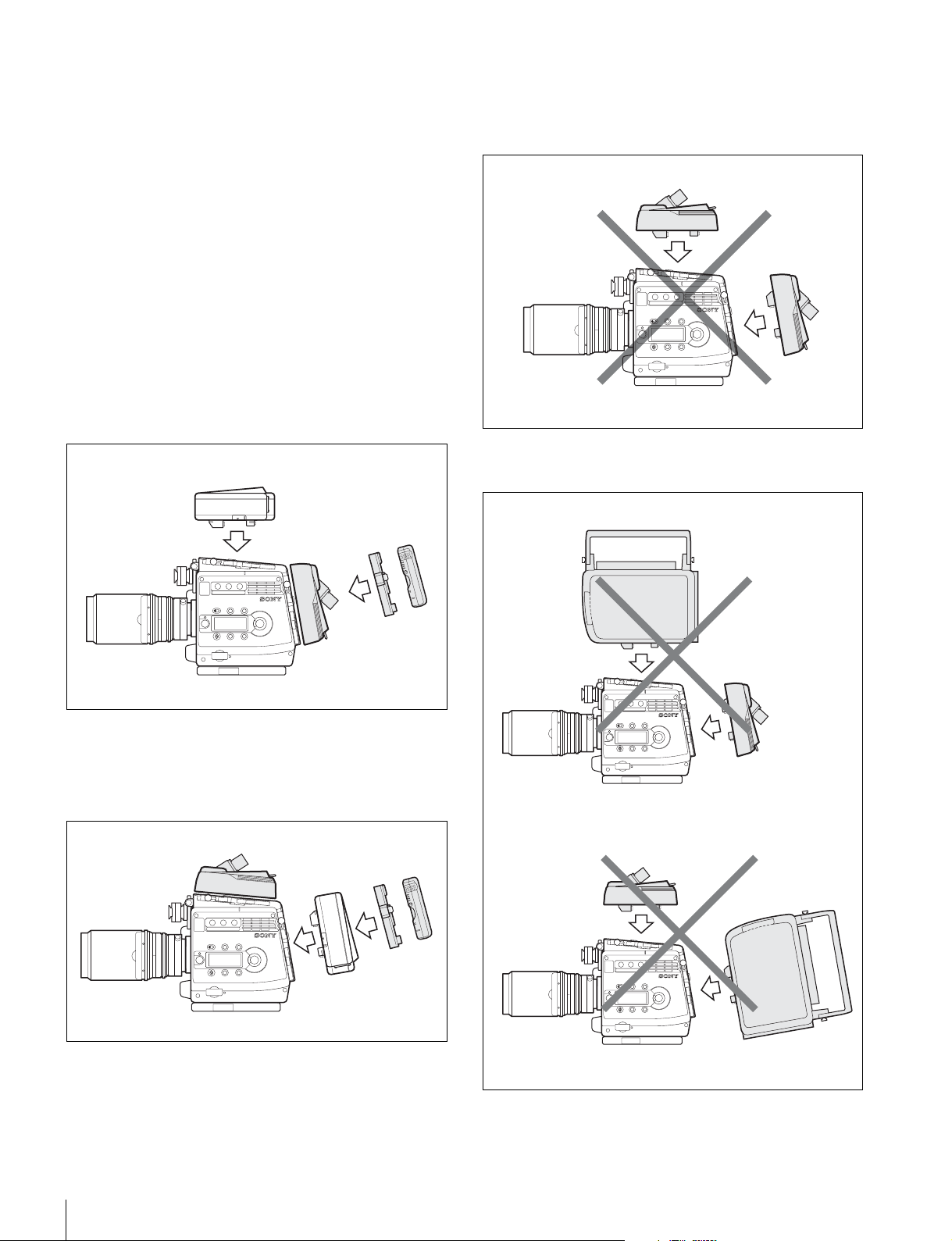
インターフェースボックスと同時に使用する
使用できない例
には
カメラに付属のインターフェースボックスと同時に使用する
ことができます。
ただし、下記の制限があります。
• GENLOCK のマスター信号は、常にレコーダーからの信号
になります。光接続システムに GENLOCK をかける際は、
SRPC-1 側の REFIN を使用してください。この場合はカ
メラ側の GENLOCKIN は無効になります。
• インターフェースボックスの SDI出力は、A/B 共に常にカ
メラ本線の画像となります。
• カメラ側へのオーディオ信号入力には、インターフェース
ボックスを使用してください。
本機をカメラ後面に取り付ける
インターフェースボックスはカメラ上面に取り付けます。
バッテリーは本機に取り付けて使用します。
インターフェースボックス
BKP-L551
+
BP-GL95
CA-F101
本機を上面、後面の両方に取り付けて使用することはできま
せん。
CA-F101
CA-F101
F23/F35
本機と SRW-1 を同時にカメラに取り付けて使用すること
はできません。
SRW-1
F23/F35
本機をカメラ上面に取り付ける
インターフェースボックスはカメラ後面に取り付けます。
バッテリーはインターフェースボックスに取り付けて使用し
ます。
CA-F101
インターフェース
ボックス
F23/F35
BKP-L551
+
BP-GL95
CA-F101 またはインターフェースボックスの DCIN 端子経
由のカメラへの給電は、それぞれカメラ後面に取り付けた場
合にのみ有効です。ここから給電する場合は、カメラ本体の
電源スイッチ(CAMPOWER) を CA 側に倒します。
CA-F101
F23/F35
CA-F101
SRW-1
F23/F35
概要
6
Page 7
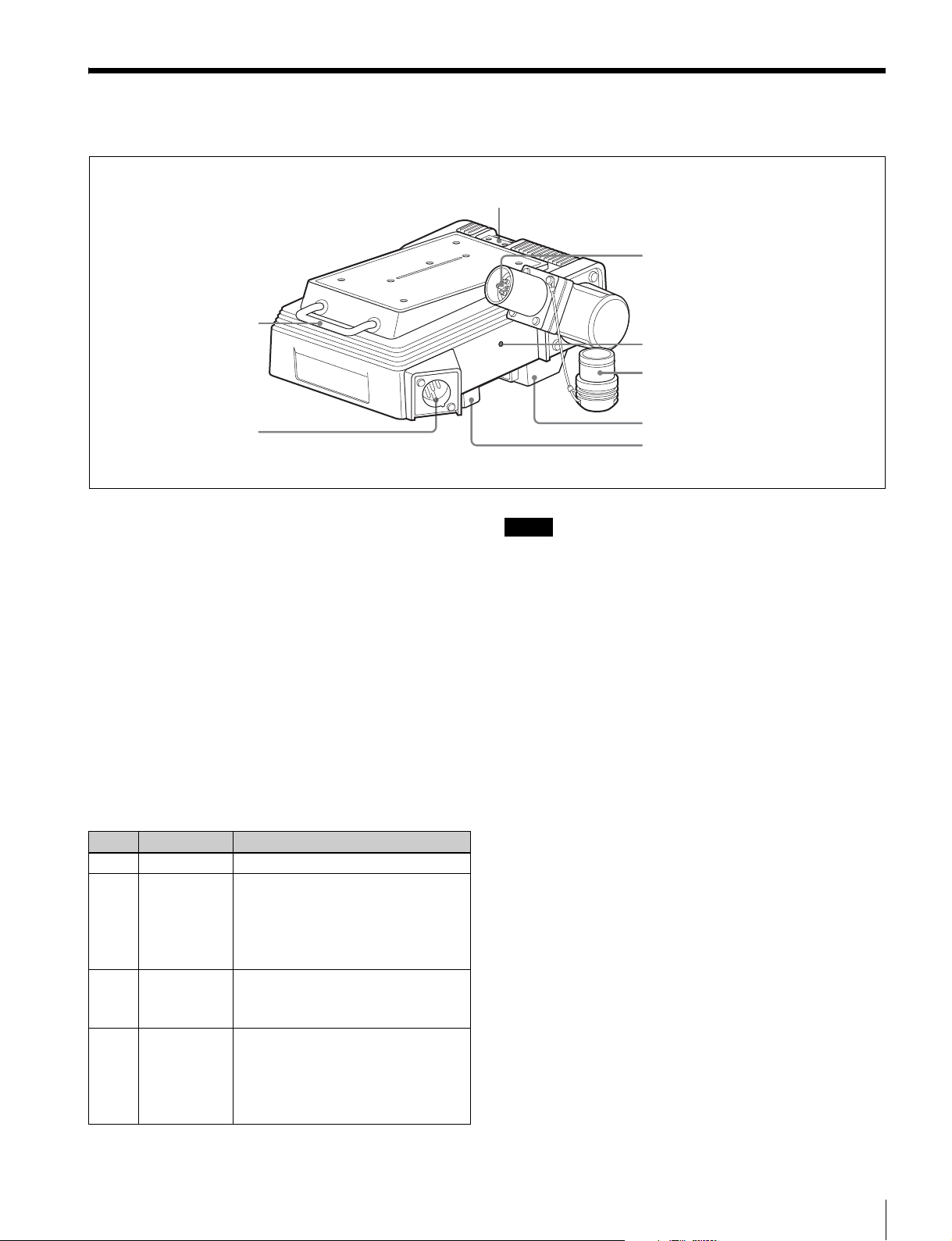
各部の名称と働き
ビューファインダーシュー取り付け部(10 ページ参照)
c VTR コネクター
a ケーブルハンガー
7V
7V
-1
-1
.5
.5
0
0
1
1
IN
IN
C
C
D
D
b DCIN 端子
a ケーブルハンガー
結束バンドなどでケーブルを固定することができます。
b DCIN(DC 電源入力)端子(XLR 型 4 ピン)
バッテリーアダプター BKP-L551 や規定の電源ケーブルを接
続して、カメラ本体および本機に電源を供給します。本機を
カメラ後面に取り付けたときのみ有効です。
c VTR コネクター(光複合コネクター、凹型)
光複合カメラケーブルを使用して、SRPC-1 に装着した
HKSR-101 の CAMERA コネクターと接続します。
d OPT(光レベル)インジケーター
カメラとレコーダー間で通信が確立すると点灯して、光レベ
ルの状態を表示します。
T
T
P
P
O
O
d OPT インジケーター
VTR コネクター用ゴムキャップ
e カメラ接続端子 1
f カメラ接続端子 2
ご注意
カメラとレコーダー間の光複合カメラケーブルが長い場合
や、ケーブルの勘合が多い場合も、光レベルが低下します。
e カメラ接続端子1
カメラと映像・音声信号およびコントロール信号の受け渡し
を行います。
f カメラ接続端子 2
カメラと電源の受け渡しを行います。
◆ 本機とカメラの電源の受け渡しについて詳しくは、11 ページを
ご覧ください。
点灯色 意味 対応
緑 正常レベル
黄 注意レベル 使用上問題ないレベルですが、光複合コネ
クターが汚れている可能性があります。
本機および光複合ケーブルの光コンタクト
部のクリーニングをおすすめします(13
ページ参照)。
赤 警告レベル 本機および光複合ケーブルの光コンタクト
部をただちにクリーニングしてください
(13 ページ参照)。
消灯 無信号、または
使用不可レベル
本機および光複合ーケーブルの光コンタク
ト部をただちにクリーニングしてください
(13 ページ参照)。クリーニングしても点灯
しない場合は、接続やレコーダーの動作状
態を確認してください。
各部の名称と働き
7
Page 8
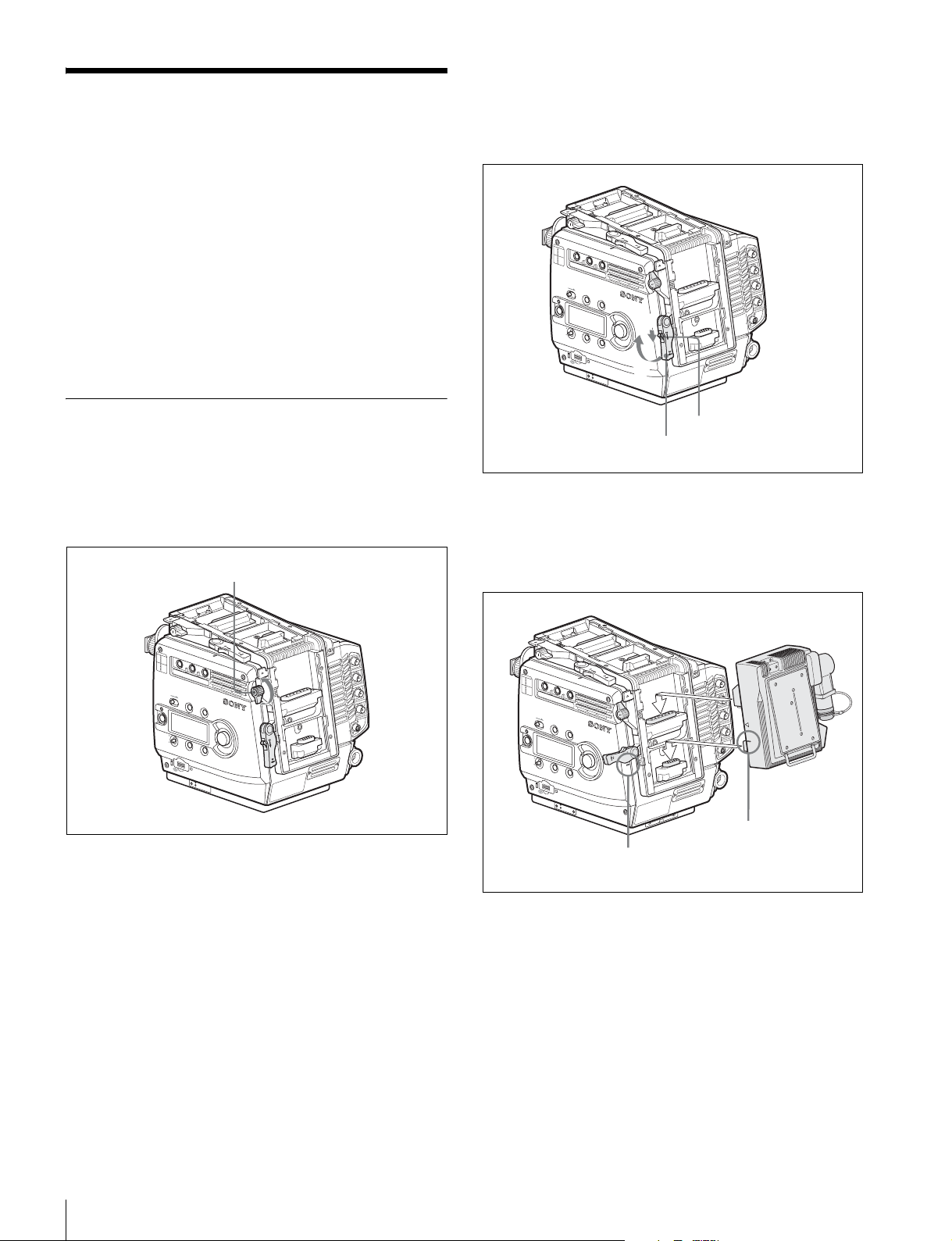
取り付け
本機は、カメラの上面または後面にマウントすることができ
ます。
カメラと本機との間は、マウントすることで接続され、ケー
ブル接続の必要はありません。
• カメラ側の着脱機構は、F23/F35、上面 / 後面で共通です。
• 以下、後面に取り付ける場合の図を例にして説明します。
• 図は F23 を例にして、カメラの L ハンドルを取りはずした
状態を示していますが、L ハンドルを取り付けたままで
も、本機の取り付け / 取りはずしが可能です。
3
ロックリリースつまみを矢印の方向にスライドしてロッ
クをはずし ( 下図 1)、アクセサリーマウントレバーを
上げる(上面マウント時はレンズ方向に引く)( 下図
2)。
N
FFO
F
I
L
T
E
R
1
CLEAR
1
2
ND
1/4 ND
3
1/16ND
4
2
1/64ND
5
CAP
A
5600K
3
B
CC
3200K
C
4300K
D
6300K
E
1/2 ND
L
O
C
K
VF MENU/DISPLAY
CANCEL/STATUS
R
U
N
4
A
U
T
O
B
L
K
B
A
L
P
A
G
E
P
R
O
1
S
E
T
2
O
E
T
O
M
E
R
本機をカメラに取り付けるには
1
カメラを安定した水平な台の上に置く。
2
アクセサリークランプレバーを上(上面マウント時はレ
ンズ方向)に回す。
アクセサリークランプレバー
N
O
FF
F
I
L
T
E
R
1
CLEAR
1
2
ND
1/4 ND
3
1/16ND
4
2
1/64ND
5
CAP
A
5600K
3
B
CC
3200K
C
4300K
D
6300K
E
1/2 ND
L
O
C
K
VF MENU/DISPLAY
CANCEL/STATUS
R
U
N
4
A
U
T
O
B
L
K
B
A
L
P
A
G
E
S
E
T
P
R
O
O
E
T
O
M
E
R
ロックリリースつまみ
アクセサリーマウントレバー
4
本機の位置合わせラインをカメラ側のラインに合わせて
はめ込み、奥まで入ったら 2 箇所のコネクターがそれぞ
れかみ合うように押し下げる(上面マウント時はレンズ
と反対の方向にスライドさせる)。
N
O
FF
F
I
L
T
E
R
1
CLEAR
1
2
ND
1/4 ND
3
1/16ND
4
2
1/64ND
5
CAP
A
5600K
3
B
CC
3200K
C
4300K
D
6300K
E
1/2 ND
L
O
C
K
VF MENU/DISPLAY
CANCEL/STA
TUS
RU
N
4
AUTO
B
L
K
B
A
L
PA
G
E
S
E
T
P
RO
カメラ側位置合わせライン
O
LOCK
E
T
O
M
E
R
アダプター側
位置合わせライン
8
取り付け
Page 9
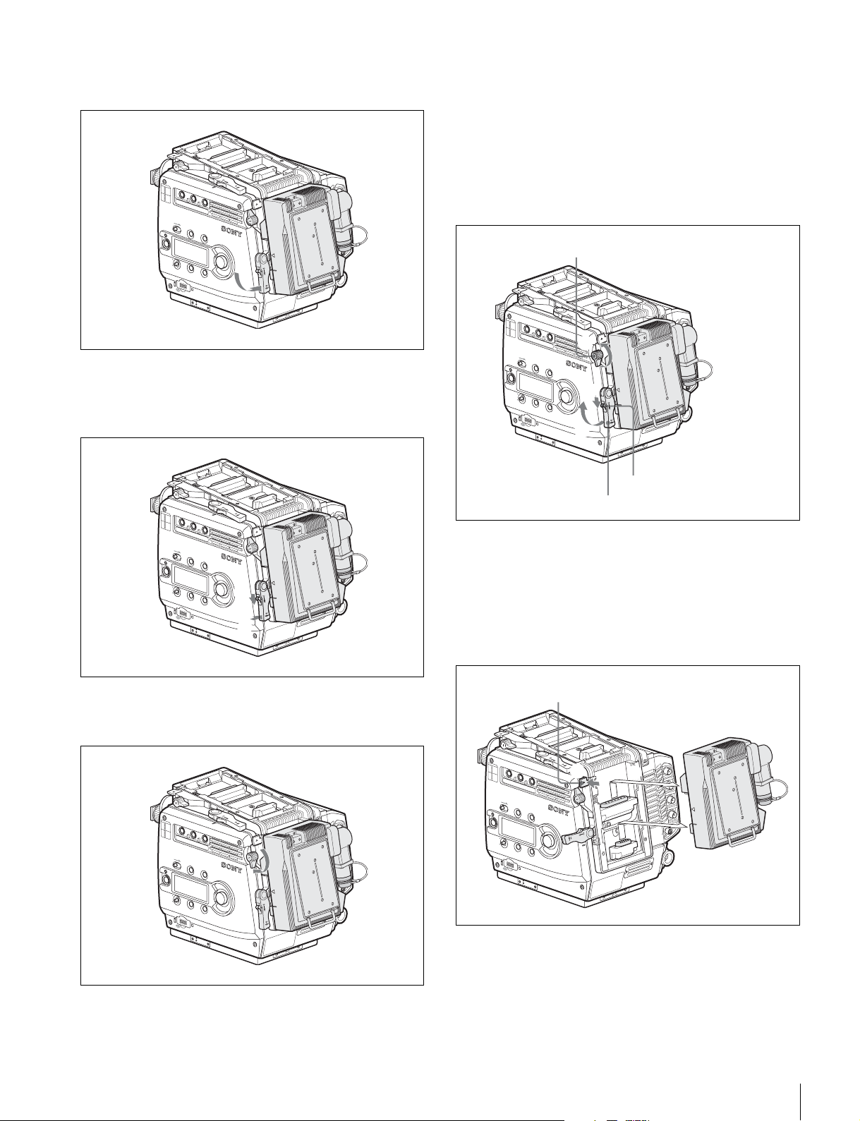
5
アクセサリーマウントレバーを押し下げる(上面マウン
ト時はレンズと反対の方向に引く)。
ON
F
F
I
L
T
E
R
1
CLEAR
1
2
ND
1/4 ND
3
1/16ND
4
2
1/64ND
5
CAP
A
5600K
3
B
CC
3200K
C
4300K
D
6300K
E
1/2 ND
L
O
C
K
VF MENU/DISPLAY
CANCEL/S
TATUS
R
U
N
4
AUTO
B
L
K
B
A
L
PA
G
E
S
E
T
P
R
O
6
ロックリリースつまみを矢印方向にスライドさせたま
OF
LOCK
E
T
O
M
E
R
ま、アクセサリーマウントレバーを折りたたむようにし
て所定の位置に収納する。
本機をカメラから取りはずすには
1
アクセサリークランプレバーを上(上面マウント時はレ
ンズ方向)に回す ( 下図 1)。
2
ロックリリースつまみを矢印方向にスライドしてロック
をはずし ( 下図 2)、アクセサリーマウントレバーを上
げる ( 下図 3)(上面マウント時はレンズ方向に引く)。
アクセサリークランプレバー
N
O
FF
F
I
L
T
E
R
1
CLEAR
1
2
ND
1/4 ND
3
1/16ND
4
2
1/64ND
5
CAP
A
5600K
3
B
CC
3200K
C
4300K
D
6300K
E
1/2 ND
L
O
C
K
VF MENU/DISPLAY
RU
N
4
AUTO
B
L
K
B
A
L
PA
G
P
RO
1
CANCEL/S
TATUS
M
E
N
U
S
E
L
E
/
N
T
E
R
2
E
S
E
T
3
O
LOCK
E
T
O
M
E
R
N
O
FF
F
I
L
T
E
R
1
CLEAR
1
2
ND
1/4 ND
3
1/16ND
4
2
1/64ND
5
CAP
A
5600K
3
B
CC
3200K
C
4300K
D
6300K
E
1/2 ND
L
O
C
K
VF MENU/DISPLAY
CANCEL/S
TATUS
R
U
N
4
AUTO
B
L
K
B
A
L
PA
G
E
P
R
O
7
アクセサリークランプレバーを下(上面マウント時はレ
1
S
E
T
2
O
LOCK
E
T
O
M
E
R
ンズと反対の方向)に回す。
ON
FF
F
I
L
T
E
R
1
CLEAR
1
2
ND
1/4 ND
3
1/16ND
4
2
1/64ND
5
CAP
A
5600K
3
B
CC
3200K
C
4300K
D
6300K
E
1/2 ND
L
O
C
K
VF MENU/DISPLAY
CANCEL/S
TATUS
R
U
N
4
AUTO
B
L
K
B
A
L
PA
G
E
S
E
T
P
R
O
O
LOCK
E
T
O
M
E
R
ロックリリースつまみ
アクセサリーマウントレバー
3
セーフティリリースを内側に向かって押しながら本機を
持ち上げてコネクターの接続をはずし、水平方向に引き
抜く。
(上面マウント時は、セーフティリリースを下に押しな
がら本機をレンズ方向にスライドさせてコネクターの接
続をはずし、垂直に持ち上げて引き抜く。)
セーフティリリース
N
O
FF
F
I
L
T
E
R
1
CLEAR
1
2
ND
1/4 ND
3
1/16ND
4
2
1/64ND
5
CAP
A
5600K
3
B
CC
3200K
C
4300K
D
6300K
E
1/2 ND
L
O
C
K
VF MENU/DISPLAY
CANCEL/S
RU
N
4
AUTO
B
L
K
B
A
L
PA
G
E
P
RO
4
TATUS
S
E
T
5
O
LOCK
E
T
O
M
E
R
4
アクセサリーマウントレバーとアクセサリークランプレ
バーを元の位置に戻す。
取り付け
9
Page 10
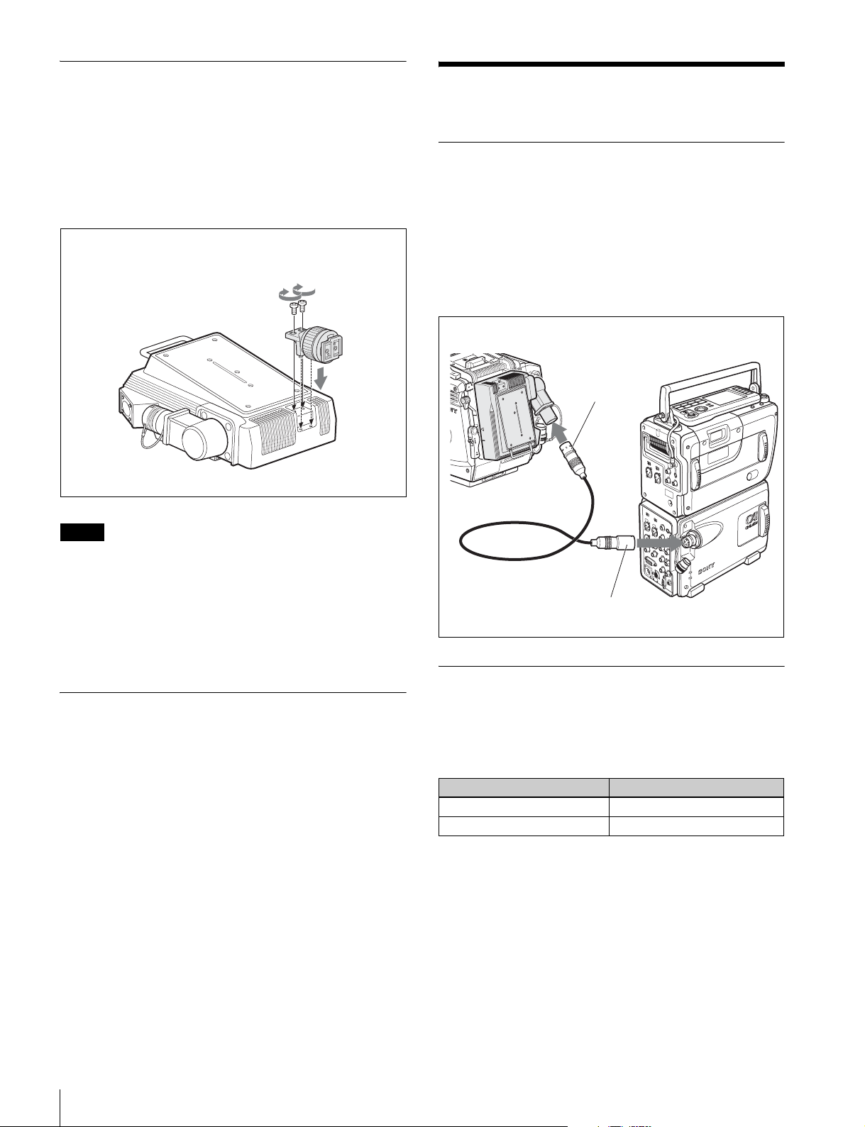
ビューファインダーを本機に取り付け るには
本機をカメラの上面にマウントしたときは、本機に付属の
ビューファインダーシューを使用して、ビューファインダー
を本機に取り付けることができます。
ビューファンダーシューを付属のネジ 2 本で本機に固定しま
す。
ビューファインダーシューと
取り付けネジ(付属)
D
C
IN
1
0
.5
-
1
7
V
レコーダーの接続と設定
接続
SRW-1 に装着した SRPC-1(HKSR-101)と本機とを接続し
ます。
接続には、ARIB(BTAS-1005B)、ANSI/SMPTE(304M1998/311M-1998)、または EBU(R100-1999) に準拠した光複
合カメラケーブル(別売り)を使用してください。
光複合カメラケーブルの最大延長距離は、1km です。
F23/F35
N
O
F
F
O
L
O
C
K
CA-F101
VTR コネクターへ
E
T
O
M
E
R
SRW-1
ご注意
本体に L ハンドルが装着されている場合は、ビューファイ
ンダーの位置、フード部の回転位置により、取り付けに制限
を受ける場合があります。
◆ ビューファインダーの取り付けかたについては、カメラおよび
ビューファインダーのオペレーションマニュアルを参照してくだ
さい。
本機にセンターハンドル(カメラに付 属)を取り付けるには
カメラに付属のセンターハンドルを本機に取り付けることが
できます。
◆ 取り付け方法は、カメラに付属のインターフェースボックスに取
り付ける場合と同様です。カメラのオペレーションマニュアルを
参照してください。
光複合カメラケーブル
CAMERA コネクターへ
INFO
WER
PO
SRPC-1
+ HKSR-101
レコーダー側の設定
上記のようにカメラに光接続して使用する場合、SRW-1 の
VIDEO メニューの VIDEOI/O の各項目を次のように設定
してください。
VIDEOI/O 項目 設定
VAINPUT CAM(Optical)
CAMTYPE STD
レコーダーの接続と設定
10
Page 11
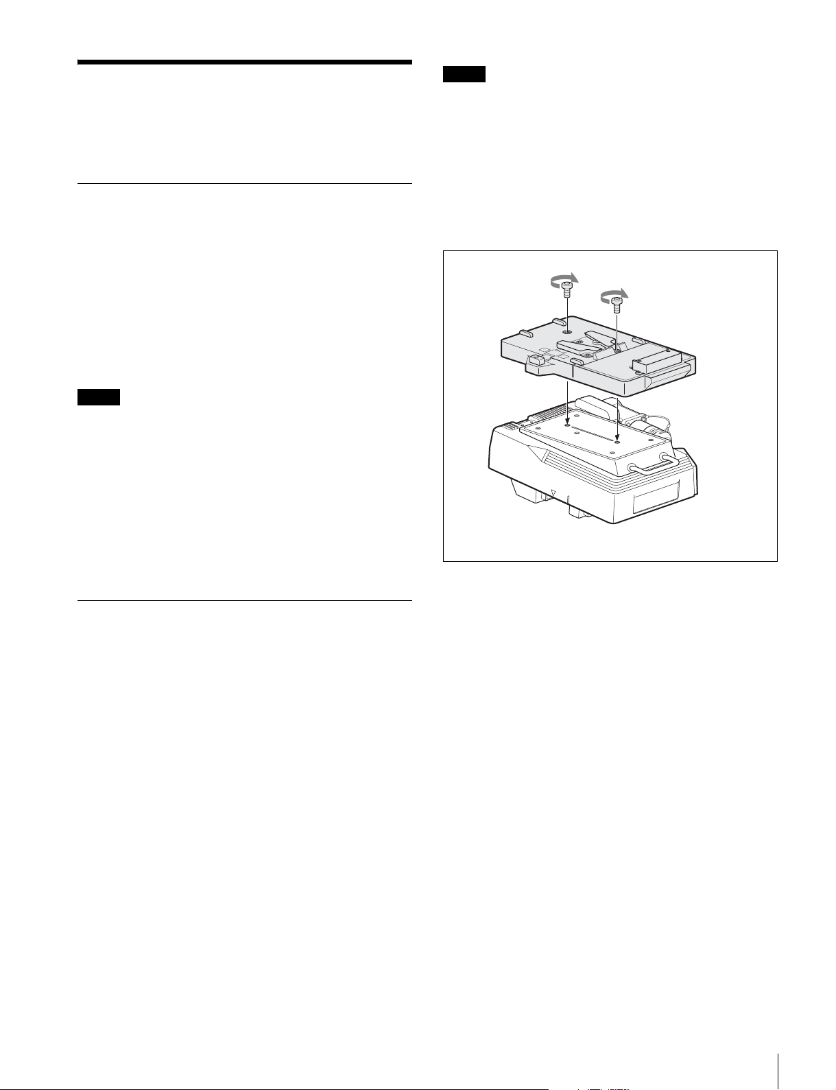
電源
本機は DC12V(10.5 〜 17V)で動作します。
カメラ電源の接続と操作
本機を介してカメラに給電する
本機をカメラ後面に取り付けた場合は、本機の DCIN 端子
(XLR4 ピン)に接続した電源を、本機を介してカメラに給
電することができます。
次項「本機への電源の接続」を参照して本機に電源を接続し、
カメラの CAMPOWER スイッチを CA 側に設定してくださ
い。
ご注意
本機をカメラ上面に取り付けたときは、本機を介してカメラ
に給電することはできません。
ご注意
• 本機を長時間使用しない場合は、バッテリーパックをはず
しておいてください。
• ご使用になる前に、専用のバッテリーチャージャーを使っ
て充電してください。
◆ 充電の方法については、バッテリーチャージャーの取扱説明書を
ご覧ください。
1
バッテリーアダプター BKP-L551 を本機に取り付ける。
BKP-L551
V
7
1
-
.5
0
1
N
I
C
D
カメラに直接給電する
カメラ側の DCIN 端子(LEMO8 ピン)に電源を接続した
ときは、カメラの CAMPOWER スイッチを ON 側に設定す
ると、カメラの上面または後面に取り付けた本機へも電源が
供給されます。
本機への電源の接続
AC 電源を使用するときは
AC アダプター AC-DN2B を使用すれば、本機に AC 電源を
接続できます。
1
AC-DN2B を本機に取り付ける。
2
AC-DN2Bに付属のDC 電源コードを本機の DCIN端子に
接続する。
3
AC-DN2B を AC 電源に接続する。
バッテリーパックを使用するときは
L
O
C
K
CA-F101
2
BP-GL95 の溝を BKP-L551 の突起に合わせてはめ、コネ
クター同士が接続されるように BP-GL95 をスライドさ
せる。
3
BKP-L551 の DC ケーブルを本機の DCIN 端子に接続す
る。
ソニーのリチウムイオンバッテリーパック BP-GL95 を使用
できます。
バッテリーアダプター BKP-L551 を本機に取り付けて、リチ
ウムイオンバッテリーパック BP-GL95 を本機に接続してく
ださい。
電源
11
Page 12

動作の確認
本機を使用してビデオレコーダーと接続した場合は、F23/
F35 のサブディスプレイやモニター画面で、接続の状態など
を確認することができます。
レベルの状態を8セグメントで表示します。
6 〜 8 セグメントが点灯:正常
3 〜 5 セグメントが点灯:注意レベル
1 または 2 セグメントのみ点灯:警告レベル
1 つも点灯しない:無信号または使用不可レベル
◆ それぞれ本機の OPT インジケーターの表示の意味と共通です。
対応については、7 ページをご覧ください。
ご注意
Ver1.2 以前の F23/F35 は、バージョンアップが必要です。
サービス担当者にご相談ください。
サブディスプレイ表示
カメラ側面にあるサブディスプレイのシステムステータス表
示ページで光レベルを確認することができます。
◆ サブディスプレイの操作方法については、F23 または F35 のオ
ペレーションマニュアルをご覧ください。
CAM:
xxxxxxxx
VTR:
xxxxxxxx
CAM:カメラ側の受光レベル
VTR:SRW-1 側の受光レベル
レベルの状態を8セグメントで表示します。
6 〜 8 セグメントが点灯:正常
3 〜 5 セグメントが点灯:注意レベル
1 または 2 セグメントのみ点灯:警告レベル
1 つも点灯しない:無信号または使用不可レベル
◆ それぞれ本機の OPT インジケーターの表示の意味と共通です。
対応については、7 ページをご覧ください。
b
b
FUNCTION 画面
カメラに接続したモニターに表示される FUNCTION 画面で
光レベルを確認することもできます。
◆ FUNCTION 画面の表示方法については、F23 または F35 のオペ
レーションマニュアルをご覧ください。
FUNCTION
xxxxxxxxxxxxxxxxxxxxxxxx
FORMAT: 59.94i 4:2:2
(30)FPS
AS1:OFF
AS2:OFF
AS3:OFF
AS4:OFF
レベル表示
OPT LVL CAM:
VTR:
xxxxxxxx
xxxxxxxx
b
b
DIAGNOSIS メニュー
カメラに接続したモニターに表示される DIAGNOSIS メ
ニューの <SYSTEMSTATUS> ページで、接続や受光の状
態を確認することができます。
◆ メニューの操作方法については、F23 または F35 のオペレー
ションマニュアルをご覧ください。
<SYSTEM STATUS> D01 TOP
DOCKING STATUS
TOP :-- REAR :OPT CA- VTR
OPTICAL STATUS
t
VTR
CAM
DOCKINGSTATUS
カメラの上面(TOP)および後面(REAR)に装着されてい
る機器を表示します。
ーーー:装着機器なし
IFBOX:カメラに付属のインターフェースボックス
VTR:ビデオレコーダー SRW-1
OPTCA:本機(本機を介して SRW-1 と接続されると、
表示が OPTCA − VTR に切り換わります。)
(IFBOX)、(OPTCA):装着されている機器が使用でき
ない組み合わせの場合は括弧付きで表示されます。
OPTICALSTATUS
信号の送受信が開始されると、カメラ側の受光状態(VTR
→ CAM)とレコーダー側の受光状態(CAM → VTR)を表
示します。
OK:正常
CARE:注意レベル
WARNING:警告レベル
NG:使用不可レベル
NOSIGNAL:無信号
◆ それぞれ本機の OPT インジケーターの表示の意味と共通です。
対応については、7 ページをご覧ください。
CAM :OK
t
VTR :OK
12
OPTLVL
CAM:カメラ側の受光レベル
VTR:SRW-1 側の受光レベル
動作の確認
Page 13
警告 / エラーメッセージ
本機に異常が発生した場合は、ビューファインダーやモニ
ター画面に、次のようなメッセージが表示されます。
メッセージ
LASERSHUTDOWN
意味
レーザーモジュール保護回路作動
原因
本機内部の温度が限界まで上昇したため、レーザーモジュー
ル保護回路が作動しました。
対策
カメラと本機への電源を切り、内部温度が充分下がるまで放
置してください。電源を再投入することによって復帰しま
す。
電源を再投入しても復帰しない場合は、ソニーのサービス担
当者にご相談ください。
保守
光ファイバーコネクターの取り扱い
光ファイバーケーブルの接続端面にほこりなどが付着すると
伝送エラーが発生します。
光ファイバーコネクターの接続端面にほこりなどが付着しな
いように、使用する前に必ずクリーニングしてください。
また、光ファイバーコネクターを使用しないときは、必ず
キャップをはめてください。
コネクターのクリーニング
本機に光ファイバーケーブルを接続する際には、本機の
VTR コネクターとケーブル側のコネクターの光コンタクト
部をクリーニングしてから接続してください。
クリーニングは以下の手順で行ってください。
光コネクタークリーナー(市販品)が入手可
能な場合
必要な治工具
• 光コネクタークリーナー(市販品)
NTT-MECLETOP
ティックタイプ)
・ クリーニング時、アルコール等は不要です。
・ この製品 1 本で 1 回の清掃が可能です。
クリーニング方法
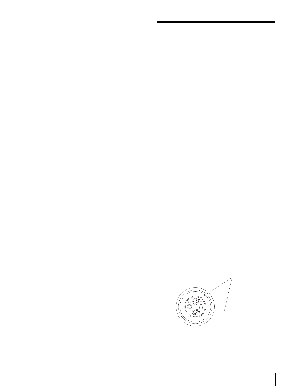
• 凸コネクター
光コネクタークリーナーで、光コンタクト先端(白)をク
リーニングしてください。
®
14100402 または 14100403 相当品(ス
光コンタクト(白)
• 凹コネクター
1
光コネクタークリーナーをまっすぐ挿入する。
保守
13
Page 14
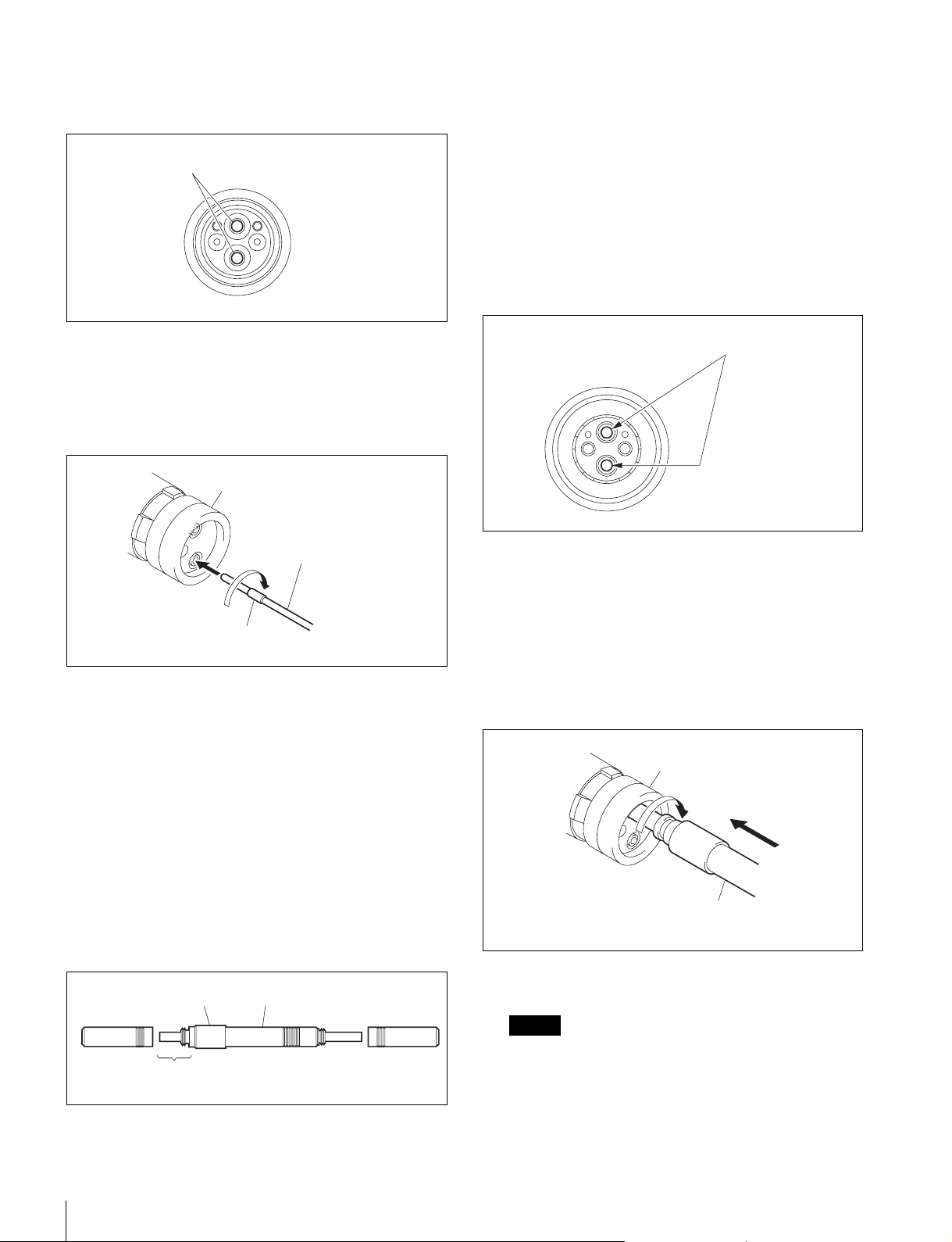
2
光コンタクトが押し下がる程度に押す。
(荷重 600g 〜 700g 程度)
光コンタクト(白)
• 綿棒(市販品)
綿棒は、直径 4mm 程度のものを使用してください。
5mm を超えると綿棒がコネクターの奥に十分に入らず、
光コンタクトの先端をクリーニングすることができませ
ん。
• アルコール(市販品)
クリーニング方法
• 凸コネクター
アルコールを浸した綿棒で、光コンタクト先端(白)をク
リーニングしてください。
3
光コンタクト先端に光コネクタークリーナーを押し付け
て、時計まわりに 4 〜 5 回転させる。
このとき、支持部付近を持って作業すると、荷重をかけ
やすくなります。
アライメントスリーブ
光コネクタークリーナー
支持部
光コネクタークリーナー(市販品)が入手で
きない場合
必要な治工具
• アライメントスリーブ引き抜き治具
ター用)
ソニー J-6480-010-A またはレモジャパン(株)
DCC.91.312.5LA相当品
HC-001
(凹コネク
光コンタクト(白)
• 凹コネクター
凹コネクターは光コンタクトがむき出しになっていませ
ん。あらかじめアライメントスリーブを外し、光コンタク
トをむき出しにする必要があります。下記の手順で行って
ください。
1
アライメントスリーブ引き抜き治具をアライメントス
リーブにまっすぐ挿入し、時計方向に回す。
アライメントスリーブ
先端の短い方を使用してください。
この治具は緩衝機構部を備えています。使用時は緩衝機構
部を持たず、必ず柄の部分を持ってください。
柄
14
緩衝機構部
先端が短い方を使用する。
保守
アライメントスリーブ引
き抜き治具
2
回転が止まったら、治具をまっすぐに強く引き抜く。
ご注意
治具の先端にアライメントスリーブが付いたまま抜けま
すが、その状態のまま取り付けることができます。
アライメントスリーブを紛失したり、破損したりしない
ように充分注意してください。
(アライメントスリーブ:部品番号 9-980-074-01)
Page 15
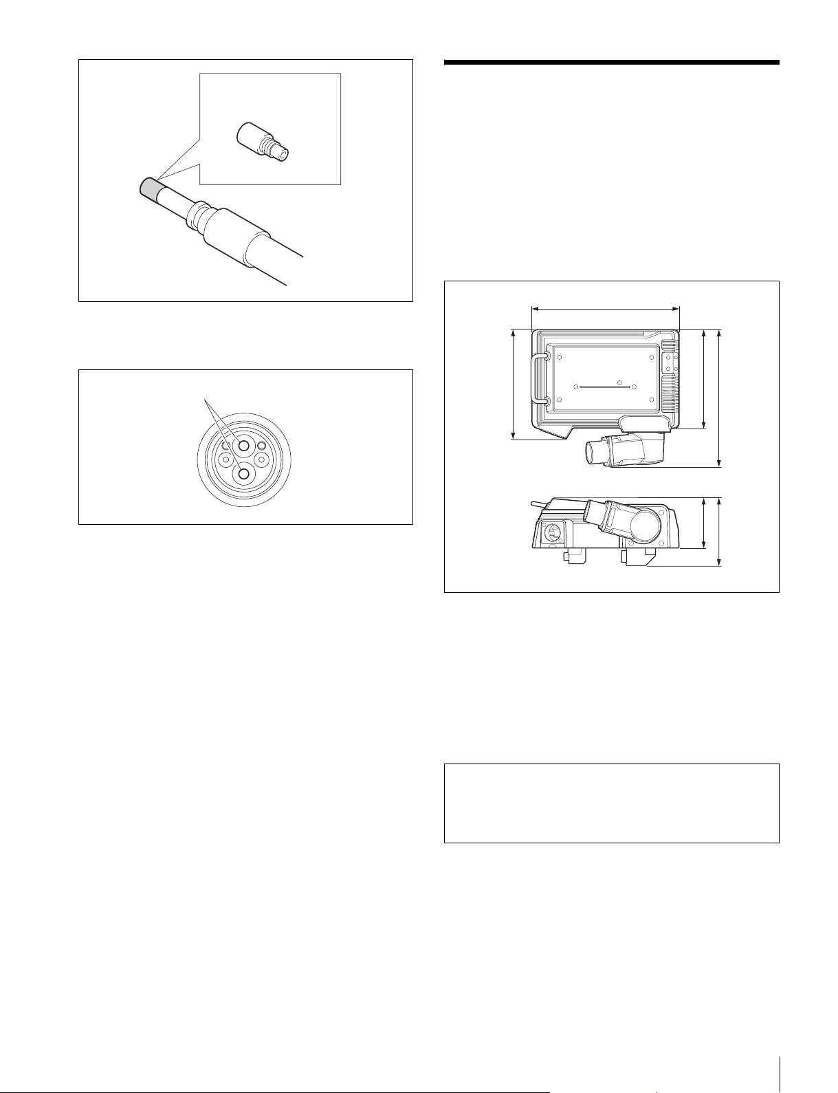
アライメントスリーブ
3
アルコールを浸した綿棒で、光コンタクト先端(白)を
クリーニングする。
仕様
一般
電源 DC10.5 〜 17V
消費電力 4.5Wmax.
動作温度 0 ℃〜+ 40 ℃
保存温度 − 20 ℃〜+ 60 ℃
質量 約720g
外形寸法( 単位 :mm)
151
光コンタクト(白)
4
アライメントスリーブが付いたままの治具を再び挿入
し、カチッと音がするまで押し込む。
5
治具を反時計方向に回してアライメントスリーブを取り
付け、治具を抜く。
112
DC IN 10.5-17V
101
52
140
69
入出力端子
VTR コネクター LEMO光 / 電気マルチコネクター(1)
DCIN 端子 XLR 型 4 ピン、凸型(1)
仕様および外観は、改良のため予告なく変更することがあり
ますが、ご了承ください。
お使いになる前に、必ず動作確認を行ってください。故障
その他に伴う営業上の機会損失等は保証期間中および保証
期間経過後にかかわらず、補償はいたしかねますのでご了
承ください。
仕様
15
Page 16
English
For the customers in the U.S.A.
This equipment has been tested and found to comply with the
limits for a Class A digital device, pursuant to Part 15 of the
FCC Rules. These limits are designed to provide reasonable
protection against harmful interference when the equipment is
operated in a commercial environment. This equipment
generates, uses, and can radiate radio frequency energy and,
if not installed and used in accordance with the instruction
manual, may cause harmful interference to radio
communications. Operation of this equipment in a residential
area is likely to cause harmful interference in which case the
user will be required to correct the interference at his own
expense.
You are cautioned that any changes or modifications not
expressly approved in this manual could void your authority to
operate this equipment.
All interface cables used to connect peripherals must be
shielded in order to comply with the limits for a digital device
pursuant to Subpart B of Part 15 of FCC Rules.
For the customers in Europe
This product with the CE marking complies with the EMC
Directive issued by the Commission of the European
Community.
Compliance with this directive implies conformity to the
following European standards:
• EN55103-1: Electromagnetic Interference (Emission)
• EN55103-2: Electromagnetic Susceptibility (Immunity)
This product is intended for use in the following
Electromagnetic Environments: E1 (residential), E2
(commercial and light industrial), E3 (urban outdoors), E4
(controlled EMC environment, ex. TV studio).
indiquées dans les documents de service ou de garantie
séparés.
Für Kunden in Europa
Dieses Produkt besitzt die CE-Kennzeichnung und erfüllt die
EMV-Richtlinie der EG-Kommission.
Angewandte Normen:
• EN55103-1: Elektromagnetische Verträglichkeit
(Störaussendung)
• EN55103-2: Elektromagnetische Verträglichkeit
(Störfestigkeit)
Für die folgenden elektromagnetischen Umgebungen: E1
(Wohnbereich), E2 (kommerzieller und in beschränktem
Maße industrieller Bereich), E3 (Stadtbereich im Freien) und
E4 (kontrollierter EMV-Bereich, z.B. Fernsehstudio).
Der Hersteller dieses Produkts ist Sony Corporation, 1-7-1
Konan, Minato-ku, Tokyo, Japan.
Der autorisierte Repräsentant für EMV und Produktsicherheit
ist Sony Deutschland GmbH, Hedelfinger Strasse 61, 70327
Stuttgart, Deutschland. Bei jeglichen Angelegenheiten in
Bezug auf Kundendienst oder Garantie wenden Sie sich bitte
an die in den separaten Kundendienst- oder
Garantiedokumenten aufgeführten Anschriften.
The manufacturer of this product is Sony Corporation, 1-7-1
Konan, Minato-ku, Tokyo, Japan.
The Authorized Representative for EMC and product safety is
Sony Deutschland GmbH, Hedelfinger Strasse 61, 70327
Stuttgart, Germany. For any service or guarantee matters
please refer to the addresses given in separate service or
guarantee documents.
Pour les clients en Europe
Ce produit portant la marque CE est conforme à la Directive
sur la compatibilité électromagnétique (EMC) émise par la
Commission de la Communauté européenne.
La conformité à cette directive implique la conformité aux
normes européennes suivantes :
• EN55103-1 : Interférences électromagnétiques (émission)
• EN55103-2 : Sensibilité électromagnétique (immunité)
Ce produit est prévu pour être utilisé dans les environnements
électromagnétiques suivants : E1 (résidentiel), E2
(commercial et industrie légère), E3 (urbain extérieur) et E4
(environnement EMC contrôlé, ex. studio de télévision).
Le fabricant de ce produit est Sony Corporation, 1-7-1 Konan,
Minato-ku, Tokyo, Japon.
Le représentant autorisé pour EMC et la sécurité des produits
est Sony Deutschland GmbH, Hedelfinger Strasse 61, 70327
Stuttgart, Allemagne. Pour toute question concernant le
service ou lagarantie, veuillez consulter les adresses
This Optical Fiber Camera Adapter is classified as a CLASS 1
LASER PRODUCT.
Caution
The use of optical instruments with this product will increase
eye hazard.
Use of controls or adjustments or performance of procedures
other than those specified herein may result in hazardous
radiation exposure.
16
Page 17
Table of Contents
Overview................................................................................18
Basic System Configuration ......................................................18
Locations and Functions of Parts.......................................20
Mounting................................................................................21
Attaching the Adapter to the Camera ........................................21
Attaching a Viewfinder to the Adapter......................................23
Attaching the Center Handle (Supplied With the Camera) to
This Adapter....................................................................23
Connection and Setting of the Recorder............................23
Connection .................................................................................23
Settings on the Recorder ............................................................23
Preparing the Power Supply................................................24
Connection and Operation for Camera Power...........................24
Supplying Power to the Adapter................................................24
Operation Check ...................................................................25
Maintenance ..........................................................................26
Handling the Optical Fiber Connectors .....................................26
Cleaning of Connectors/Cable...................................................26
Specifications .......................................................................28
GB
Table of Contents
17
Page 18
Overview
The CA-F101 Optical Fiber Camera Adapter is designed to
be directly mounted on a Sony F23 or F35 Digital
Cinematography Camera, achieving signal transmission
and interface between the camera and the SRW-1 HD
Portable Digital Recorder/SRPC-1 HD Video Processor
via a hybrid optical camera cable.
Video of RGB4:4:4 up to 1080/30P or Y Cb Cr 4:2:2 up to
1080/60P can be transmitted along with 2-channel audio
and control signals via a single hybrid optical camera cable
(1 km long at maximum).
In a system where the camera and recorder are to be
operated in the undocked condition, the number of cables
between the camera and recorder can be decreased, for
smooth system operations.
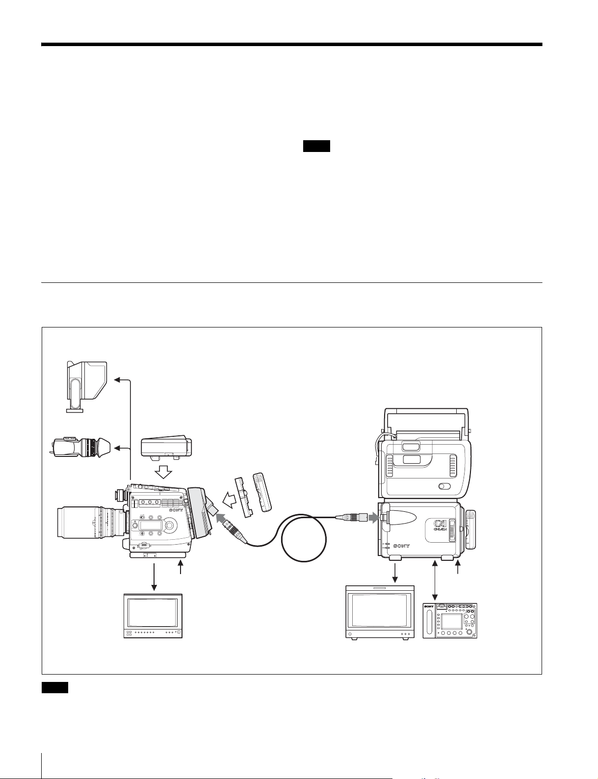
Basic System Configuration
This unit is designed assuming usage in the following system.
Viewfinder
Various camera controls, including the Select FPS
function, are also enabled by connecting a camera remote
control unit to the recorder as the base station.
Note
When using the CA-F101, confirm that the devices to be
used in combination match the following requirements:
• The HKSR-101 Optical Interface Unit has been mounted
on the SRPC-1 HD Video Processor.
• The F23/F35 Digital Cinematography Camera is Ver. 1.3
or later.
• The SRW-1 and SRPC-1 are Ver. 2.6 or later.
• When using the Select FPS function, the HKSR-102
Picture Cache Board has been installed in the SRW-1.
a) Cable that conforms to ARIB (BTA S-1005B), ANSI/SMPTE (304M-1998/
311M-1998), or EBU (R100-1999)
b)The RM-B750 can also be connected to the RM connector of the camera.
Note however that simultaneous connection to both the camera and recorder
is not allowed. Camera menu operations from the LCD of the RM-B750 is
enabled only when the RM-B750 is connected to the camera.
Interface box
HDVF-C950W
(supplied with F23/F35)
SRW-1
HD Portable
Digital Recorder
SRPC-1
HD Video
Processor
+ HKSR-101
Optical Interface
Unit
b)
HDVF-C35W
ff
60
30
20
15
12
10
8
7
6
5.6
5
4.6
F23/F35 Digital
Cinematography
Camera
BKP-L551 Battery Adaptor
+ BP-GL95 Battery Pack
1
123
FILTER
1
CLEAR
2
1/4 ND
ND
3
1/16ND
4
1/64ND
5
CAP
A
5600K
B
3200K
CC
C
4300K
D
6300K
E
1/2 ND
T
1.6
2
2.8
4
5.6
8
11
16
CL
LOCK
VF MENU/DISPLAY CANCEL/STATUS
RUN
4
AUTO
BLK
BAL
PAGE
PRO
4 : 2 : 2
HD monitor
CA-F101
1
SET
DC 12 V power
Hybrid optical camera cable
a)
4 : 2 : 2
HD monitor
DC 12 V power
RM-B750
Remote Control Unit
Note
Power supply via the hybrid optical camera cable is not included in this system. Supply power independently to the camera
and the recorder.
18
Overview
Page 19
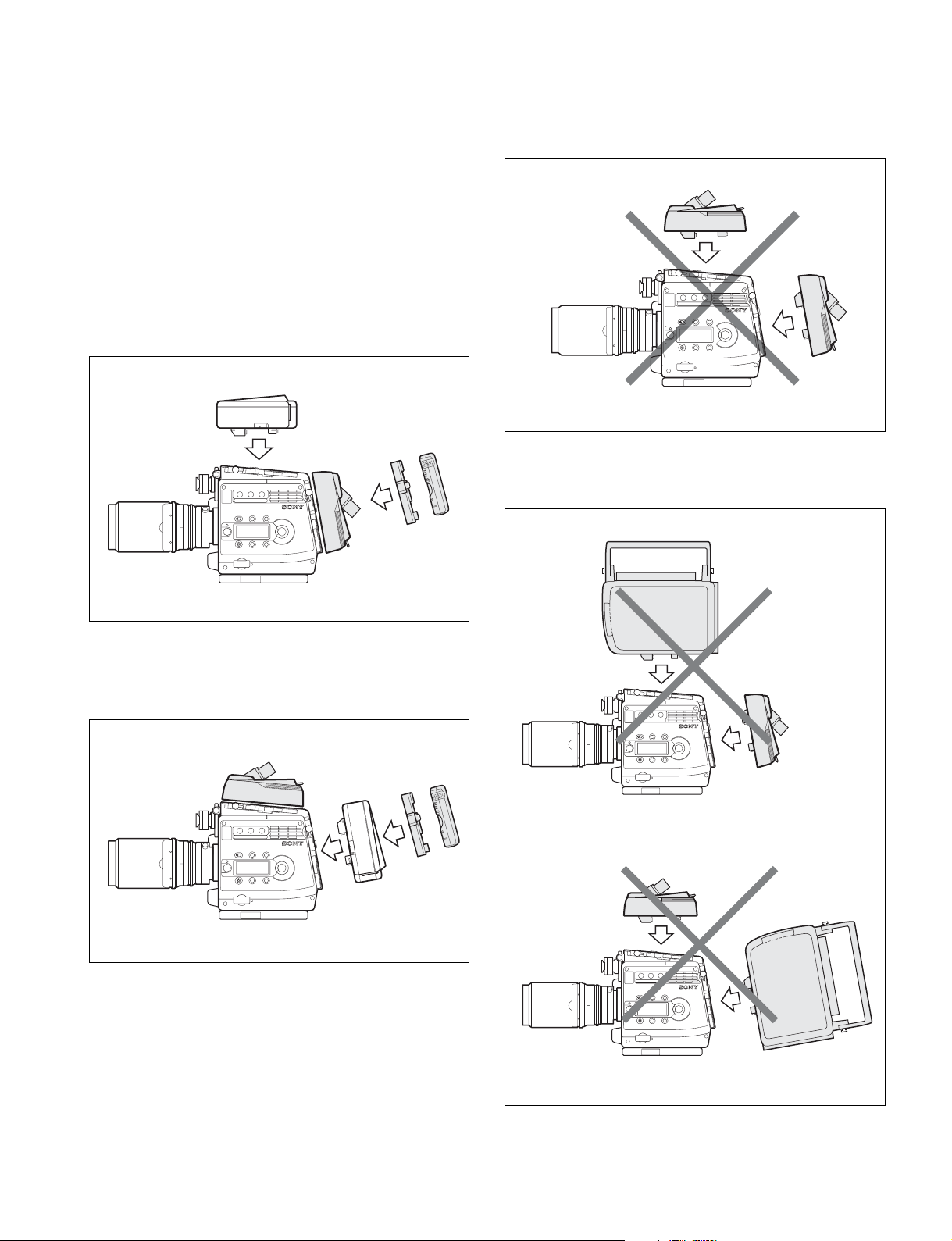
Using the interface box in combination
The interface box supplied with the camera can be
simultaneously used, with the following limitations:
• The GENLOCK master signal is always the signal from
the recorder. For GENLOCK of the optical connection
system, use REF IN of the SRPC-1. GENLOCK IN to
the camera is then disabled.
• Both SDI outputs A and B from the interface box are
always the camera images of the main line.
• For audio inputs to the camera, use the interface box.
Attaching the CA-F101 to the rear of the camera
The interface box can be attached to the top of the camera.
Attach the battery to the CA-F101.
Interface box
Examples of invalid combinations
You cannot use two CA-F101 units simultaneously
attached to the top and rear of the camera.
CA-F101
CA-F101
BKP-L551
+
BP-GL95
CA-F101
F23/F35
Attaching the CA-F101 to the top of the camera
The interface box can be attached to the rear of the camera.
Attach the battery to the interface box.
CA-F101
BKP-L551
+
BP-GL95
F23/F35
You cannot use a CA-F101 and an SRW-1
simultaneously attached to the camera.
SRW-1
CA-F101
F23/F35
Interface box
F23/F35
Power supply to the camera via the DC IN connector of the
CA-F101 or the interface is enabled only with either unit
attached to the rear of the camera. To operate on this power
supply, set the CAM POWER switch of the camera to the
CA side.
CA-F101
F23/F35
SRW-1
Overview
19
Page 20
Locations and Functions of Parts
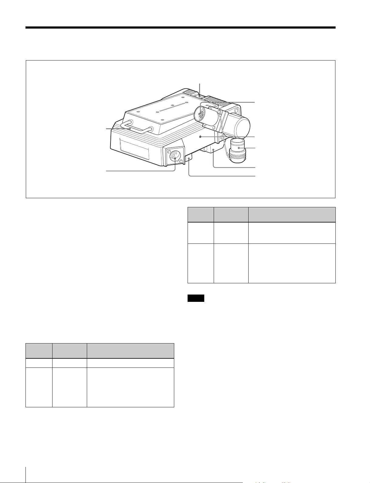
Viewfinder shoe receptacle (see page 23)
c VTR connector
a Cable hanger
b DC IN connector
1
IN
C
D
a Cable hanger
You can fix cables on this, using bundlers.
b DC IN connector (XLR 4-pin)
Connecting the BKP-L551 Battery Adaptor or a specified
power cable, supply power to the camera and this unit. This
is effective only when this unit is mounted on the rear of
the camera.
c VTR connector (optical/electric composite
connector, female)
Connect to the CAMERA connector of the HKSR-101
mounted on the SRPC-1 using a hybrid optical camera
cable.
d OPT (optical level) indicator
It lights up when communication between the camera and
recorder is established, indicating the optical level status.
Lighting
color
Green Normal level
Yellow Cautioning
Meaning Measures to be taken
Sufficient for operation, but the
level
optical contacts may have some
dirt.
It is recommended to clean the
optical contacts of the unit and the
cable (see page 26).
V
7
-1
0.5
T
P
O
Lighting
d OPT indicator
Rubber cap for the
VTR connector
e Camera connector 1
f Camera connector 2
Meaning Measures to be taken
color
Red Warning
level
Immediately clean the optical
contacts of the unit and the cable
(see page 26).
Unlit No signal, or
unusable
level
Immediately clean the optical
contacts of the unit and the cable
(see page 26). If the indicator
remains unlit, check the
connections and the recorder
operation.
Note
The optical level is also decreased if the camera cable
between the camera and the recorder is long or has many
junctions.
e Camera connector 1
Video/audio and control signals are sent/received to/from
the camera.
f Camera connector 2
Power is sent/received to/from the camera.
For details on power supply, see page 24.
Locations and Functions of Parts
20
Page 21
Mounting
The adapter can be attached to the top or rear of the
camera.
Connection between the camera and the adapter is
achieved by mounting, thus eliminating additional cable
connections.
• The same attaching/detaching system is used both on the
top and the rear on the F23/F35.
• The following instructions use the illustrations of
attaching to the rear of the F23 as examples.
• Although the illustrations show the statuses where the L
handle has been detached, the interface box can be
mounted/unmounted with the L handle attached.
Attaching the Adapter to the Camera
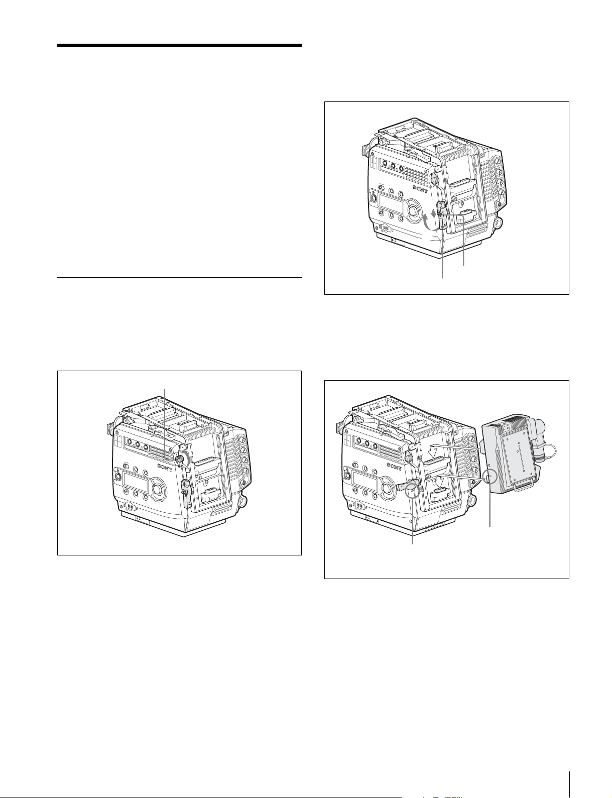
1
Place the camera head on a stable, flat surface.
2
Rotate the accessory clamp lever upward (toward the
lens when attaching to the top).
3
Release the lock by sliding the lock-release knob in the
direction of the arrow (1 in the figure below) then pull
up on the accessory mount lever (pull it toward the lens
when mounting on the top) (2 in the figure below).
N
O
FF
F
I
L
T
E
R
1
CLEAR
1
2
ND
1/4 ND
3
1/16ND
4
2
1/64ND
5
CAP
A
5600K
3
B
CC
3200K
C
4300K
D
6300K
E
1/2 ND
L
O
C
K
VF MENU/DISPLAY
CANCEL/STATUS
R
U
N
4
A
U
T
O
B
L
K
B
A
L
P
A
G
E
P
R
O
1
S
E
T
2
O
E
T
O
M
E
R
Lock-release knob
Accessory mount lever
4
Aligning the matching line on the adapter with that on
the camera, fit the adapter into the camera then push
down on the adapter (slide it in the opposite direction
of the lens when attaching to the top) so that the
connectors engage.
Accessory clamp lever
N
O
N
FFO
F
I
L
T
E
R
1
CLEAR
1
2
ND
1/4 ND
3
1/16ND
4
2
1/64ND
5
CAP
A
5600K
3
B
CC
3200K
C
4300K
D
6300K
E
1/2 ND
L
O
C
K
VF MENU/DISPLAY
CANCEL/STATUS
R
U
N
4
A
U
T
O
B
L
K
B
A
L
P
A
G
E
S
E
T
P
R
O
O
E
T
O
M
E
R
F
I
L
T
E
R
1
CLEAR
1
2
ND
1/4 ND
3
1/16ND
4
2
1/64ND
5
CAP
A
5600K
3
B
CC
3200K
C
4300K
D
6300K
E
1/2 ND
L
O
C
K
VF MENU/DISPLAY
CANCEL/STA
TUS
RU
N
4
AUTO
B
L
K
B
A
L
PA
G
E
S
E
T
P
RO
OFF
LOCK
E
T
O
M
E
R
Matching line on
Matching line on
the adapter
the camera
Mounting
21
Page 22
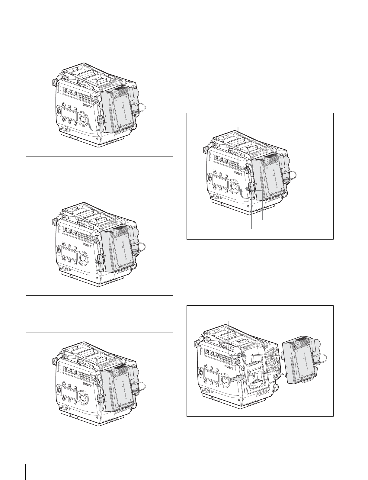
5
Rotate the accessory mount lever downward (pull on it
in the opposite direction of the lens when attaching to
the top).
N
O
F
F
I
L
T
E
R
1
CLEAR
1
2
ND
1/4 ND
3
1/16ND
4
2
1/64ND
5
CAP
A
5600K
3
B
CC
3200K
C
4300K
D
6300K
E
1/2 ND
L
O
C
K
VF MENU/DISPLAY
CANCEL/S
TATUS
RU
N
4
AUTO
B
L
K
B
A
L
PA
G
E
S
E
T
P
R
O
6
While holding the lock-release knob in the direction of
OF
LOCK
E
T
O
M
E
R
the arrow, fold the accessory mount lever into its home
position.
Detaching the adapter from the camera
1
Rotate the accessory clamp lever upward (toward the
lens when attaching to the top) (1 in the figure
below).
2
Release the lock by sliding the lock-release knob in the
direction of the arrow (2 in the figure below) then pull
up on the accessory mount lever (3 in the figure
below) (pull it toward the lens when mounting on the
top).
Accessory clamp lever
N
O
FF
F
I
L
T
E
R
1
CLEAR
1
2
ND
1/4 ND
3
1/16ND
4
2
1/64ND
5
CAP
A
5600K
3
B
CC
3200K
C
4300K
D
6300K
E
1/2 ND
L
O
C
K
VF MENU/DISPLAY
RU
N
4
AUTO
B
L
K
B
A
L
PA
G
E
P
RO
CANCEL/S
1
TATUS
M
E
N
U
S
E
L
E
/
N
T
E
R
2
S
E
T
3
O
LOCK
E
T
O
M
E
R
N
O
F
I
L
T
E
R
1
CLEAR
1
2
ND
1/4 ND
3
1/16ND
4
2
1/64ND
5
CAP
A
5600K
3
B
CC
3200K
C
4300K
D
6300K
E
1/2 ND
L
O
C
K
VF MENU/DISPLAY
CANCEL/S
TATUS
R
U
N
4
AUTO
B
L
K
B
A
L
PA
G
E
P
R
O
7
Rotate the accessory clamp lever downward (toward
1
S
E
T
2
OFF
LOCK
E
T
O
M
E
R
the opposite direction of the lens when attaching to the
top).
N
O
FF
F
I
L
T
E
R
1
CLEAR
1
2
ND
1/4 ND
3
1/16ND
4
2
1/64ND
5
CAP
A
5600K
3
B
CC
3200K
C
4300K
D
6300K
E
1/2 ND
L
O
C
K
VF MENU/DISPLAY
CANCEL/S
TATUS
R
U
N
4
AUTO
B
L
K
B
A
L
PA
G
E
S
E
T
P
R
O
O
LOCK
E
T
O
M
E
R
Lock-release knob
Accessory mount lever
3
While holding the safety release tab pressed inward,
pull up on the adapter to disengage the connectors,
then pull out the adapter horizontally.
(When attaching to the top, hold the safety release tab
pressed downward, slide the adapter toward the lens to
disengage the connectors, then pull out the adapter
vertically.)
Safety release tab
N
O
FF
F
I
L
T
E
R
1
CLEAR
1
2
ND
1/4 ND
3
1/16ND
4
2
1/64ND
5
CAP
A
5600K
3
B
CC
3200K
C
4300K
D
6300K
E
1/2 ND
L
O
C
K
VF MENU/DISPLAY
CANCEL/S
RU
N
4
AUTO
B
L
K
B
A
L
PA
G
E
P
RO
4
TATUS
S
E
T
5
O
LOCK
E
T
O
M
E
R
22
Mounting
4
Return the accessory mount lever and accessory clamp
lever to their home positions.
Page 23
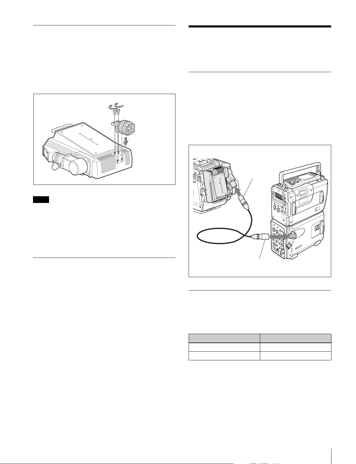
Attaching a Viewfinder to the Adapter
When the adapter is mounted on the top of the camera, a
viewfinder can be attached to the adapter, using the
viewfinder shoe supplied with the adapter.
Fix the viewfinder shoe to the adapter with the supplied
two screws.
Viewfinder shoe
and fixing
screws
(supplied)
D
C
I
N
1
0
.5
-
1
7
V
Note
When the L handle is attached to the camera, the attaching
condition may be limited, owing to the viewfinder position
and the rotating position of the hood.
Connection and Setting of the Recorder
Connection
Connect between this adapter and the SRPC-1 (HKSR-
101) docked to the SRW-1.
For connection, use an optional hybrid optical camera
cable that conforms to ARIB (BTA S-1005B), ANSI/
SMPTE (304M-1998/311M-1998), or EBU (R100-1999).
The maximum allowable cable run for the hybrid optical
camera cable is 1 km.
F23/F35
N
O
F
F
L
O
C
K
CA-F101
O
to VTR connector
E
T
O
M
E
R
SRW-1
For how to attach the viewfinder, refer to the operation
manual of the camera and that of the viewfinder.
Attaching the Center Handle (Supplied With the Camera) to This Adapter
The center handle supplied with the camera can be
attached to this adapter.
The attaching method is the same as that when attaching it
to the interface box of the camera. Refer to the operation
manual of the camera and that of the viewfinder.
Hybrid optical camera cable
to CAMERA connector
INFO
ER
W
PO
SRPC-1
+ HKSR-101
Settings on the Recorder
When optically connected with the camera as shown
above, set the VIDEO I/O items of the VIDEO menu of the
SRW-1 as follows:
VIDEO I/O item Setting
VA INPUT CAM(Optical)
CAM TYPE STD
Connection and Setting of the Recorder
23
Page 24
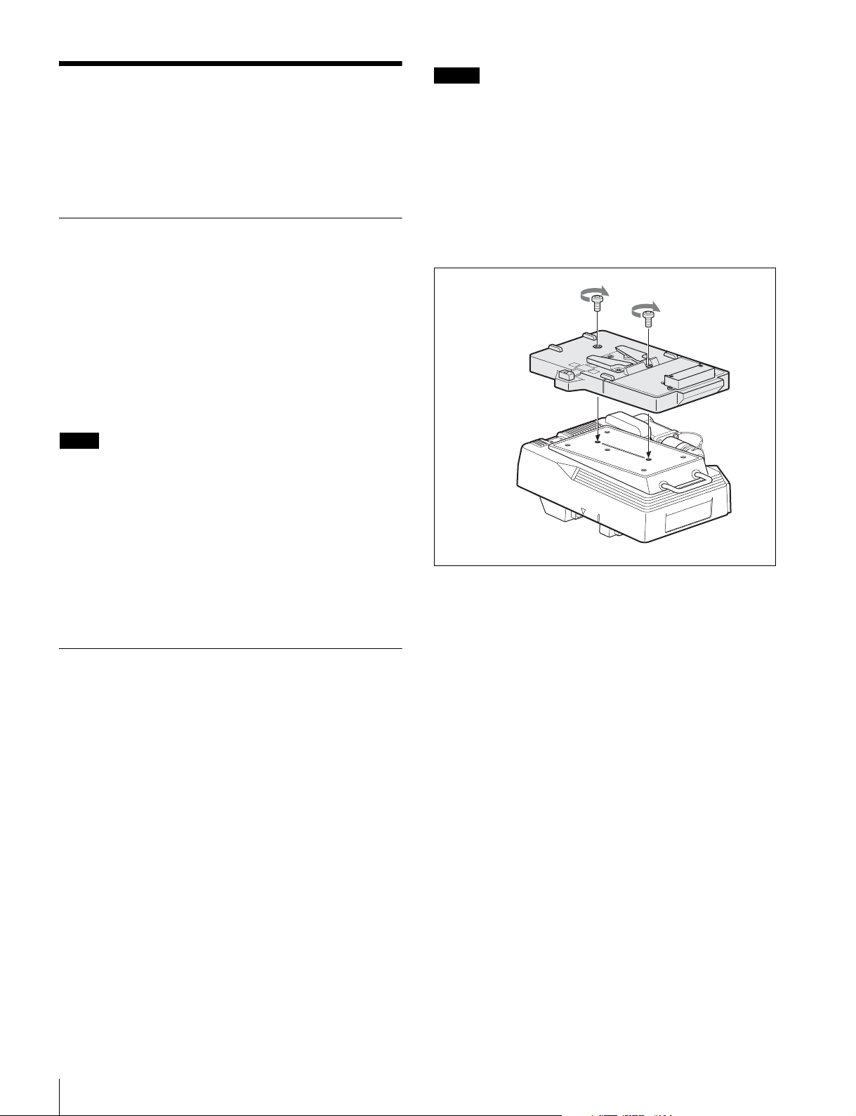
Preparing the Power Supply
Notes
• Remove the battery pack if the adapter will be out of use
for an extended period.
• Charge the battery, using the specified battery charger,
before use.
This adapter operates on 12 V (10.5 to 17 V) DC.
Connection and Operation for Camera Power
Supplying power via the CA-F101
If the adapter is attached to the rear of the camera, the
power supply to the DC IN connector (XLR 4-pin) of the
adapter is fed to the camera via the adapter.
Connect the power to the adapter as mentioned in
“Connecting a Power to the Adapter” below and set the
CAM POWER switch of the camera to the CA side.
Note
If the adapter is mounted on top, power is not fed to the
camera.
Supplying power directly to the camera
If power is supplied via the DC IN connector (LEMO 8pin) of the camera, power is also supplied to the adapter
attached to either the top or the rear of the camera when
you set the CAM POWER switch of the camera to the ON
side.
For charging, refer to the instructions for the battery
charger.
1
Attach the BKP-L551 Battery Adaptor to the CAF101.
BKP-L551
V
7
1
-
.5
0
1
IN
C
D
L
O
C
K
CA-F101
2
Aligning the groove on the BP-GL95 with the
projection on the BKP-L551, slide the BP-GL95 so
that the connectors engage.
Supplying Power to the Adapter
To use an AC power source
An AC power source can be connected, using the ACDN2B AC Adaptor.
1
Attach the AC-DN2B to the adapter.
2
Connect the DC power cord supplied with the ACDN2B to the DC IN connector of the adapter.
3
Connect the AC-DN2B to an AC power source.
To use a battery pack
The BP-GL95 Lithium-ion Battery Pack can be used.
Attach the BKP-L551 Battery Adaptor to the adapter, and
connect the BP-GL95 Lithium-ion Battery Pack to the
adapter.
3
Connect the DC cable of the BKP-L551 to the DC IN
connector of the CA-F101.
Preparing the Power Supply
24
Page 25

Operation Check
When the F23/F35 is connected to the video recorder using
this adapter, you can check the connection status on the
subdisplay of the camera and a video monitor connected to
the camera.
Note
F23/F35 before Ver 1.2 requires version upgrading.
Consult Sony service personnel.
The status of the level is indicated with eight segments.
If 6 to 8 segments are lit: Normal
If 3 to 5 segments are lit: Cautioning level
If only 1 or 2 segments are lit: Warning level
If no segment is lit: No signal or unusable level
The meanings are the same as those of the OPT indicator
of the adapter. For measures to be taken, see page 20.
DIAGNOSIS menu
The <SYSTEM STATUS> page of the DIAGNOSIS menu
displayed on a monitor connected to the camera shows the
docking and optical statuses.
Subdisplay
You can check the optical level on the system status page
of the subdisplay located on the side of the camera.
For details on subdisplay operations, refer to the
Operation Manual of the F23 or F35.
CAM:
xxxxxxxx
VTR:
xxxxxxxx
b
b
CAM: Optical reception level on the camera side
VTR: Optical reception level on the SRW-1 side
The status of the level is indicated with eight segments.
If 6 to 8 segments are lit: Normal
If 3 to 5 segments are lit: Cautioning level
If only 1 or 2 segments are lit: Warning level
If no segment is lit: No signal or unusable level
The meanings are the same as those of the OPT indicator
of the adapter. For measures to be taken, see page 20.
FUNCTION display
The optical level can also be checked on the FUNCTION
display on a monitor connected to the camera.
For details on the FUNCTION display, refer to the
Operation Manual of the F23 or F35.
FUNCTION
xxxxxxxxxxxxxxxxxxxxxxxx
FORMAT: 59.94i 4:2:2
(30)FPS
AS1:OFF
AS2:OFF
AS3:OFF
AS4:OFF
Level
indications
OPT LVL CAM:
VTR:
OPT LVL
CAM: Optical reception level on the camera side
VTR: Optical reception level on the SRW-1 side
xxxxxxxx
xxxxxxxx
b
b
For details on menu operations, refer to the Operation
Manual of the F23 or F35.
<SYSTEM STATUS> D01 TOP
DOCKING STATUS
TOP :-- REAR :OPT CA- VTR
OPTICAL STATUS
t
VTR
CAM
CAM :OK
t
VTR :OK
DOCKING STATUS
Indicates the device docked on the top or rear of the
camera.
– – –
: No device
IF BOX: Interface box supplied with the camera
VTR: SRW-1 video recorder
OPT CA: CA-F101 (Changes to “OPT CA – VTR”
when the camera is connected to the recorder via the
adapter.)
(IF BOX), (OPT CA): Indicated in parentheses if
combination use of the docked device is not allowed.
OPTICAL STATUS
Indicates the optical reception status on the camera side
(VTR
t
CAM) and that on the recorder side (CAMtVTR)
while signal transmission is in progress.
OK: Normal
CARE: Cautioning level
WARNING: Warning level
NG: Unusable level
NO SIGNAL: No signal
The meanings are the same as those of the OPT indicator
of the adapter. For the measures to be taken, see page 20.
Warning/error message
If a problem occurs in this unit, a warning is given by the
following message indication on the viewfinder or monitor
screen:
Operation Check
25
Page 26
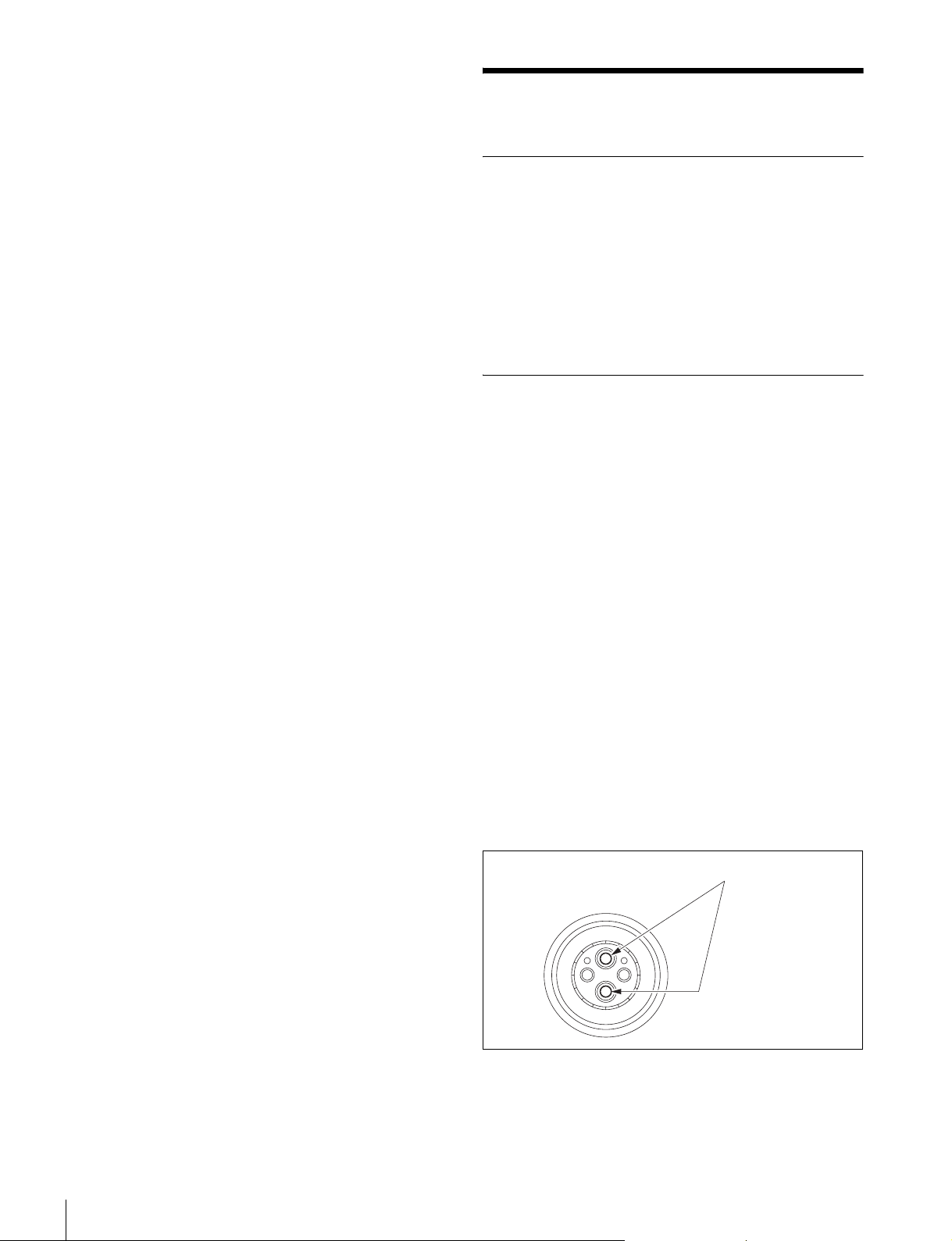
Message
LASER SHUTDOWN
Meaning
The laser-module protection circuit has been activated.
Maintenance
Cause
Once the temperature inside the unit rose up to the upper
limit, the laser-module protection circuit was activated.
Countermeasures
Turn off power to the camera and the adapter and let them
sit until the internal temperature sufficiently drops. Normal
operation will be resumed when you reapply power.
If normal operation is not resumed, the module may be
defective. Consult a Sony service personnel,
Handling the Optical Fiber Connectors
Transmission errors occur if the connection contacts of the
optical fiber cable get dirty.
Be sure to clean the connection contacts of the optical fiber
cable before use to remove any foreign matter.
When the connectors are not used, keep them covered with
caps.
Cleaning of Connectors/Cable
Before connecting an optical fiber cable to the adapter, it is
recommended to clean the optical contacts on the VTR
connector of the adapter and the optical fiber cable.
The steps for cleaning are described below.
When an optical connector cleaner (sold
separately) is available
Materials required
• Optical connector cleaner (commercially available)
Product name: NTT-ME CLETOP
14100403 or equivalent (stick type)
—Cleaning fluid, cleaning alcohol, or the like are not
necessary during cleaning.
—Each cleaning stick should only be used once.
®
14100402 or
26
Maintenance
Cleaning procedure
• Male connector
Clean the optical contact tips (white), using the optical
connector cleaner.
Optical contacts (white)
• Female connector
1
Insert the optical connector cleaner straight into the
connector.
Page 27
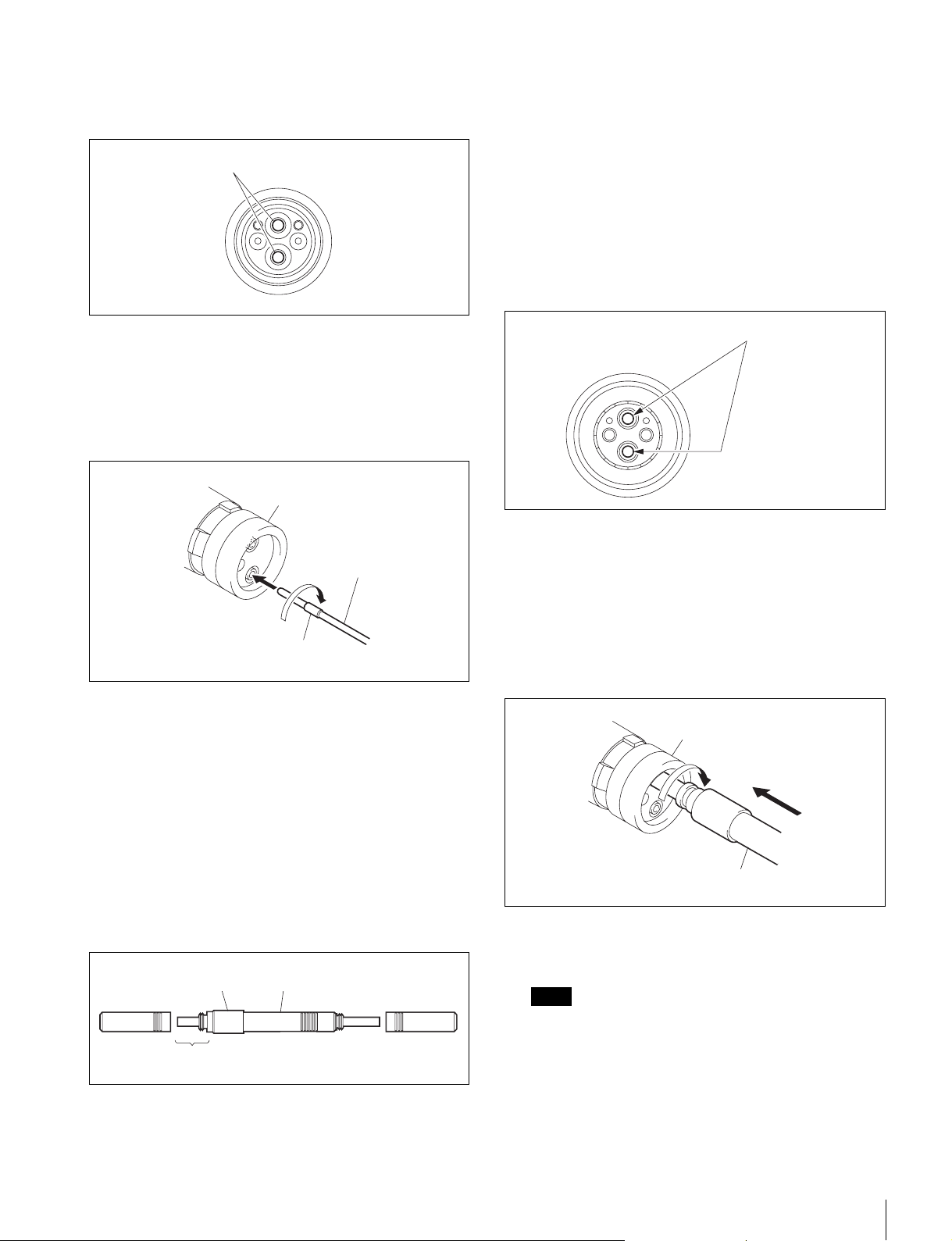
2
Apply sufficient pressure (approximately 600 g to
700 g [20 oz. to 25 oz.]) to slightly depress the optical
contact.
Optical contacts (white)
3
While pressing the optical connector cleaner against
the tip of the optical contact, rotate it clockwise four or
five times.
Gripping the support section of the optical connector
cleaner makes it easier to apply pressure.
Alignment sleeve
• Cotton swab (commercially available)
Use cotton swabs with a diameter of about 4 mm (5/32
inches). If the diameter of the cotton swab exceeds
5 mm (7/32 inches), the swab will not fit fully into the
connector, and the tip of the optical contact cannot be
cleaned.
• Cleaning alcohol (commercially available)
Cleaning procedure
• Male connector
Clean the optical contact tips (white), using a cotton
swab moistened with alcohol.
Optical contacts (white)
Optical connector
cleaner
Support section
When an optical connector cleaner (sold
separately) is not available
Materials required
• Alignment sleeve remover HC-001 (for female
connector)
Sony J-6480-010-A
Use the short-tip end of the tool.
The tool is equipped with a shock absorber. When using
the tool, always grip it by the handle, not the shock
absorber.
Shock absorber
Use short-tip end
Handle
• Female connector
The optical contacts of a female connector are not
accessible in the normal condition. To access the
contacts for cleaning, you must first remove the
alignment sleeve, as described below.
1
Insert the alignment sleeve remover straight into the
alignment sleeve, and rotate it clockwise.
Alignment sleeve
Alignment sleeve remover
2
When the remover can no longer be turned, pull it out
straight.
Note
Note
The alignment sleeve can be removed and installed
again while attached to the tip of the alignment sleeve
remover. Take care not to lose or damage the alignment
sleeve.
(Alignment sleeve part number: 9-980-074-01)
Maintenance
27
Page 28
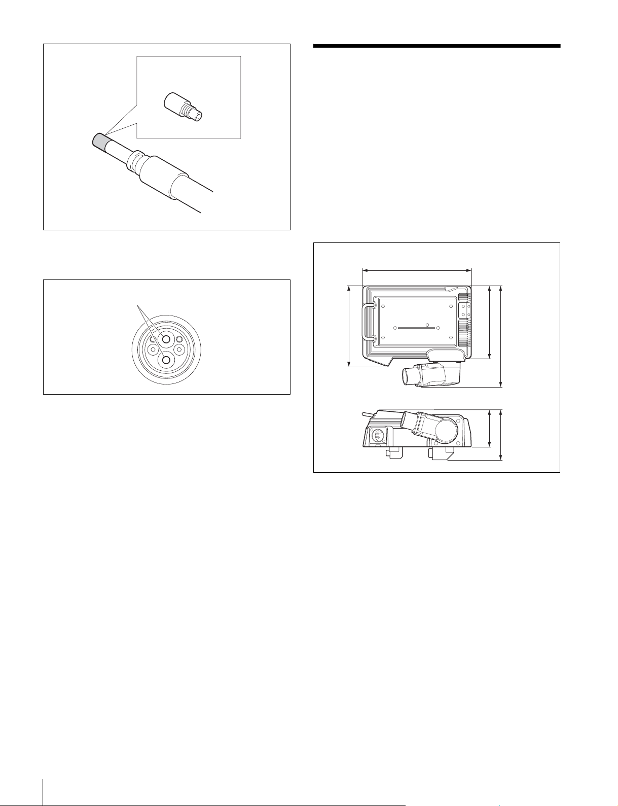
Alignment sleeve
3
Clean the optical contact tips (white), using a cotton
swab moistened with alcohol.
Optical contacts (white)
Specifications
General
Power requirements
DC 10.5–17 V
Power consumption
4.5 W max.
Operating temperature
0°C to +40°C (32°F to 104°F)
Storage temperature
−20°C to +60°C (−4°F to +140°F)
Mass Approx. 720 g (1 lb 9 oz)
Dimensions
Unit: mm (inches)
101 (4)
)
2
/
1
112 (4
151 (6)
DC IN 10.5-17V
)
8
/
5
140 (5
4
Reinsert the alignment sleeve remover with the
attached alignment sleeve into the connector and push
it in until you hear a click.
5
Rotate the alignment sleeve remover counterclockwise
to fasten the alignment sleeve. Then pull out the
alignment sleeve remover.
)
8
/
)
1
4
/
3
52 (2
69 (2
Input/output connectors
VTR connector LEMO
DC IN connector XLR type, 4-pin, male (1)
Design and specifications are subject to change without
notice.
Connectors for optical/electric composite cables:
• LEMO
® PUW.3K.93C.TLCC96 (to the “CAMERA”
connector on the VTR)
• LEMO
® FUW.3K.93C.TLMC96 (to the “VTR”
connector on the camera)
Caution on the optical/electric composite cable:
For connection between the VTR and the camera, be sure
to use an optical/electric signal composite cable with the
connectors specified in this manual in order to comply with
the limit for EMC regulations.
optical/electric composite
connector (1)
28
Specifications
Page 29

Connecteurs pour les câbles optiques/électriques
composites:
•LEMO
® PUW.3K.93C.TLCC96 (au connecteur
« CAMERA » du magnétoscope)
•LEMO
® FUW.3K.93C.TLMC96 (au connecteur
« VTR » de la caméra)
Précaution concernant le câble optique/électrique
composite:
Pour la connexion entre le magnétoscope et une caméra,
utilisez un câble optique/électrique composite avec
connecteurs spécifiés dans ce manuel pour assurer la
conformité avec la réglementation EMC.
Anschlüsse für optische/elektrische FBAS-Kabel:
•LEMO
® PUW.3K.93C.TLCC96 (an „CAMERA“-
Anschluss an dem Videorecorder)
•LEMO
® FUW.3K.93C.TLMC96 (an „VTR“-Anschluss
an der Kamera)
Vorsichtsmaßregeln für optische/elektrische FBASKabel:
Für Verbindung zwischen Videorecorder und Kamera
verwenden Sie immer ein optisches/elektrisches FBASKabel mit Steckern, wie in dieser Anleitung beschrieben,
um die Grenzwerte der geltenden EMV-Vorschriften zu
erfüllen.
Note
Always verify that the unit is operating properly before
use. SONY WILL NOT BE LIABLE FOR DAMAGES
OF ANY KIND INCLUDING, BUT NOT LIMITED
TO, COMPENSATION OR REIMBURSEMENT ON
ACCOUNT OF THE LOSS OF PRESENT OR
PROSPECTIVE PROFITS DUE TO FAILURE OF
THIS UNIT, EITHER DURING THE WARRANTY
PERIOD OR AFTER EXPIRATION OF THE
WARRANTY, OR FOR ANY OTHER REASON
WHATSOEVER.
Specifications
29
Page 30

30
Specifications
Page 31

このマニュアルに記載されている事柄の著作権は当社にあ
り、説明内容は機器購入者の使用を目的としています。
従って、当社の許可なしに無断で複写したり、説明内容
(操作、保守等)と異なる目的で本マニュアルを使用する
ことを禁止します。
The material contained in this manual consists of
information that is the property of Sony Corporation
and is intended solely for use by the purchasers of the
equipment described in this manual.
Sony Corporation expressly prohibits the duplication of
any portion of this manual or the use thereof for any
purpose other than the operation or maintenance of
the equipment described in this manual without the
express written permission of Sony Corporation.
Page 32
CA-F101 (SY)
4-118-591-01(1)
Sony Corporation
Printed in Japan
2008.09.13
© 2008
 Loading...