

Page 1
LARGE LENS ADAPTOR
CA-905K
CA-905F
CA-905T
CA-905L
BKP-9057
電気製品は、安全のための注意事項を守らないと、
警告
このオペレーションマニュアルには、事故を防ぐための重要な注意事項と
製品の取り扱いかたを示してあります。このオペレーションマニュアルを
よくお読みのうえ、製品を安全にお使いください。お読みになったあと
は、いつでも見られるところに必ず保管してください。
OPERATION MANUAL
1st Edition (Revised 2)
火災や人身事故になることがあります。
[Japanese/English]
Page 2
日本語
安全のために
電気製品は、安全のための注意事項を守らないと、火災や感電などにより死亡や
大けがな ど人身事故につながること が あり、危険です。
事故を防 ぐため に次のことを必ずお守りください。
安全のための注意事項を守る
2(J)〜4(J)ページの注意事項をよくお読みください。
オプション基板の装着について
危険を避けるために、オプション基板の装着 はサービストレーニングを受けた技術
者、もしくはソ ニーのサービス担当者または営業担当者にご依頼ください。
定期点検を実施する
長期間安全に使用していただくために、定期点検を実施することをおすすめしま
す。点検の内容や費用については、ソニーのサービス担当者または営業担当者
にご相談ください。
故障したら使用を中止する
ソニーのサービス担当者、または営業担当者にご連絡ください。
警告表示の意味
このオペレーションマニュアル
および製品では、次のような表
示をしています。表示の内容を
よく理解してから本文をお読み
ください。
この表示の注意事項を守らない
と、火災や感電などにより死亡
や大けがなど人身事故につなが
ることがあります。
この表示の注意事項を守らない
と、感電やその他の事故により
けがをしたり周辺の物品に損害
を与えたりすることがあります。
注意を促す記号
万一、異常が起きたら
1 電源を切る。
異常な音、
におい、煙が
出たら
炎が出たら
,
2 電源コードや接続コードを抜く 。
3 ソニーのサービス担当者、または営業担当者に修
すぐに電源を切り、消火 する。
,
理を依頼する。
行為を禁止する記号
行為を指示する記号
Page 3
目次
.............................................................................................................
..............................................................................................................
概要 .................................................................................................................
特長 ...................................................................................................................5(J)
システム接続例 .....................................................................................................6(J)
各部の名称と働き ............................................................................................
レンズ接合部(前面)と端子部 .........................................................................10(J)
カメラ 取り付け部(内部底面)と別売りビューファ イ ンダーサ ドル BKP-9057 .. 11(J)
後面コントロールパネル......................................................................................12(J)
三脚への取り付け...............................................................................................16(J)
カメラの組み込みと機材・付属品の取り付け .................................................
スタジオ用大型レンズの取り付け ......................................................................16(J)
カメラの組み込み ...............................................................................................17(J)
ポータブルレンズの取り付け..............................................................................20(J)
ビューフ ァインダーの取り付け(BKP-9057組み込み時)..................................22(J)
ナンバープレートの取り付け ...............................................................................23(J)
HDC用リアパネルシートの貼り付け...................................................................23(J)
主な仕様...........................................................................................................
大型レンズアダプターCA-905K/905F/905T ....................................................24(J)
大型レンズアダプターCA-905L..........................................................................24(J)
ビューフ ァインダーサ ドルBKP-9057...................................................................25(J)
2(J)
4(J)
5(J)
10(J)
16(J)
24(J)
日
本
語
1 (J)
Page 4

下記の注意を守らないと、火災や感電により
感電火災
死亡や大けがにつながることがあります。
分解しない、改造しない
分解したり、改造したりすると、感電の原 因となり ます。
内部に水や異物を入れない
水や異物が入ると火災や感電の原因となります。
万一、水や異物が入ったときは、すぐに電源を切り、ト ライアックスケーブルや接
続コードを抜いて、ソニーのサービス担当者または営業担当者にご相談ください。
油煙、湯気、湿気、ほこりの多い場所では設置・使用しない
上記のような場所で設置・使用すると、火災や感電の原因となります。
指定された
(カメラコントロールユニット)
CCU
/CA
(カメラ
アダプター)を使用する
指定以外のCCU/CAを使用すると、火災や感電の原因となります。
運搬時にカメラのハンドルを持たない
運搬時に組み込まれたカメラのハンドルを持つ と 、ハンドルが破損 して機器が落
下し、けがの原因となることがあります。
三脚の雲台を水平状態でロックしてからカメラ、レンズ、
ビューファインダー、本機を装着する
三脚の雲台を水平状態でロックしてか らカ メラ、レンズ、ビュー ファ インダー、本機
を装着しないと、機器が 落 下してけが の原因となることがあります。
トライアックスケーブル/ファイバーケーブルを傷つけない
トライアックスケーブル /ファイバーケーブ ルを傷つけると、火災や感電の原因とな
ります 。
ケーブルを加 工したり、傷つけたり しない。
•
重いものをのせた り、 引っ張ったりしない。
•
熱機器に近づけた り、加熱 したりしない。
•
ケーブルを抜くときは、必 ずプラグを持って 抜く。
•
万一、ケー ブルが傷んだら、ソニーのサービス担当者に交換をご依頼ください。
2 (J)
Page 5
下記の注意を守らないと、火災や感電により
感電火災
死亡や大けがにつながることがあります。
不良のトライアックスケーブルを使用しない
トライアックスケーブルの内側シールドは給電用とし て、また外側シールドは安全
アース として使用されま す。
安全のため、内側シールドと外側シールド間がショ ートしてい るトライ アックスケーブ
ルは使用しないでください。ショートしているトライ アックスケーブルを使用すると、
感電の原因となります。
トライアックスケーブル/ファイバーケーブルを取り外すときは
電源を切る
トライアックスケーブ ル/ファイバ ーケーブ ルをカメラから取り外すときは、本機の電
源を切ってか ら取り 外して く ださい。電源が入ったままトライア ックスケーブル/フ ァ
イバーケーブルを取り外すと、火災 や感電の原 因となり ます。
運用中およびビューファインダーを着脱する前には、ビュー
ファインダーサドルの固定ネジを確実に締める (
BKP-9057
組
み込み時)
通常運用中およびビューファインダーを着脱する前にビューフ ァ イ ンダーサ ドルの
固定ネジを締めないと、ビュ ー ファ インダーサ ドルが開閉 して、手をはさ んだ り身体
にぶつけ たりして、けがの原因となります。
3 (J)
Page 6
下記の注意を守らないと、
けがをしたり周辺の物品に損害を与えることがあります。
カメラに重量にあった三脚を使用する
カメラの重量に耐えきれない三脚または三脚以外に取り付けて使用すると、本機
やレンズが落下し、けがをするこ とがあ ります。
三脚・雲台は確実に固定する
三脚・雲台を確実に固定せずにカメラから離れると、不意にカメラが動いてけが
をすることがあります。
安定した場所に設置する
ぐらついた台の上や傾いたところな どに三脚・雲台を設置すると、カメラが落下し
てけがをする ことがあります。
機器の着脱は正しく行う
本機に以下の機器を着脱するときは、このオペレーシ ョンマニュアルの該当する
ペー ジ を よく読んだ うえ、確実に着脱してく ださい。着脱方法を誤 るとカメラ等が
落 下し、け がをすることがあります。
カメ ラ
•
レンズ
•
ビューフ ァインダー
•
Vウェッ ジシュー
•
ビューファインダーを付けたままカメラを着脱しない
ビュー ファ イン ダー を付けた まま カ メラを着脱すると 、手をは さんで けがの原因と な
ることがあります。
乱暴に運搬しない
本機は重量物ですので、落下に注意して運搬してください。
ビューファインダーサドルを開閉する際には指はさみに注意す
る(
BKP-9057
組み込み時)
4 (J)
BKP-9057を使用して7インチビュー ファ インダーで運用する ときに不用意にビュー
ファインダーを閉じると、指をはさんでけがの原因となるこ とがあり ます。
Page 7

概要
CA--905K/905F/905Tは、ト ラ イア ッ ク ス伝送カメラアダプターCA570と組み合わせたポータブルタイプのカラービデオカメラ(以下
「カ メラ 」と言います)に、スタジオレンズを取り付けるための大 型レ
ンズアダプターです。CA-905Lは、ファイバー伝送カメラアダプター
CA-950と組み合わせたカメラ、およびHDポータブルカメラHDC950 専用の大型レ ンズアダプターです。
大型レンズアダプターと5型ビューファイ ン ダーを使用する こ とによ っ
て、ポー タブルカ メラに大型レ ンズを組み合わせ たスタジオ用システ
ムの運用が可能になります。
また別売りのビューフ ァインダーサ ドルBKP-9057を使用することに
より、7 型ビューフ ァイ ンダーの接続が可能です。
特長
ソニー仕様の大型レンズに対応
ソニーハンガーマ ウントタイプ仕様の大型レンズを取り付けられま
す。フルサーボタ イ プ、手動調整 タイプのいずれにも 対応できます。
また、ポータブルレンズ(エクステンダー付き) も 使用できます。
スタジオカメラと同等の操作パネル
後面の操作パネルは、スタジオ用カラービデオカメラとほぼ同じ
機能を備えており、本機にポータブルカメラを組み込んだ状態
で、スタジオ用カメラと同等の操作性を得ること ができます。
またBKP-9057組み込み時には、PictureInPicture機能も使用で
きます(一部のカメラではPictureInPicture機能を使用できませ
ん)。
システムの組み立て、分解が容易
初期調整として、一度レンズとカ メ ラの位置調整を行う ことで、レン
ズ/カメラ装着のたびに再調整をする必要がありません。また、
BKP-9057のサドル回転機構の採用により、カメラの本 体 からの 着
脱が容易です。
軽量/省スペースシステムの実現
CCU-550A(ポータブルCCU)による大型レンズの使用が可能
(CA-905K/905T/905F使用時のみ)。
5 型ビューファインダー使用によ り、 さ ら に軽量、省スペースのシ
ステム構築が可能。
型ビューファインダーが使用可能 (
7
BKP-9057
組み込み時)
別売りビュー ファ インダーサ ドルBKP-9057を組み込むことで、7型
の白黒ビ ューファインダーやカ ラービューファ イ ンダーを使用できま
す。
ご注意
CCU-550A使用時はBVF-7700は使用しないでください。
5 (J)
Page 8
概要
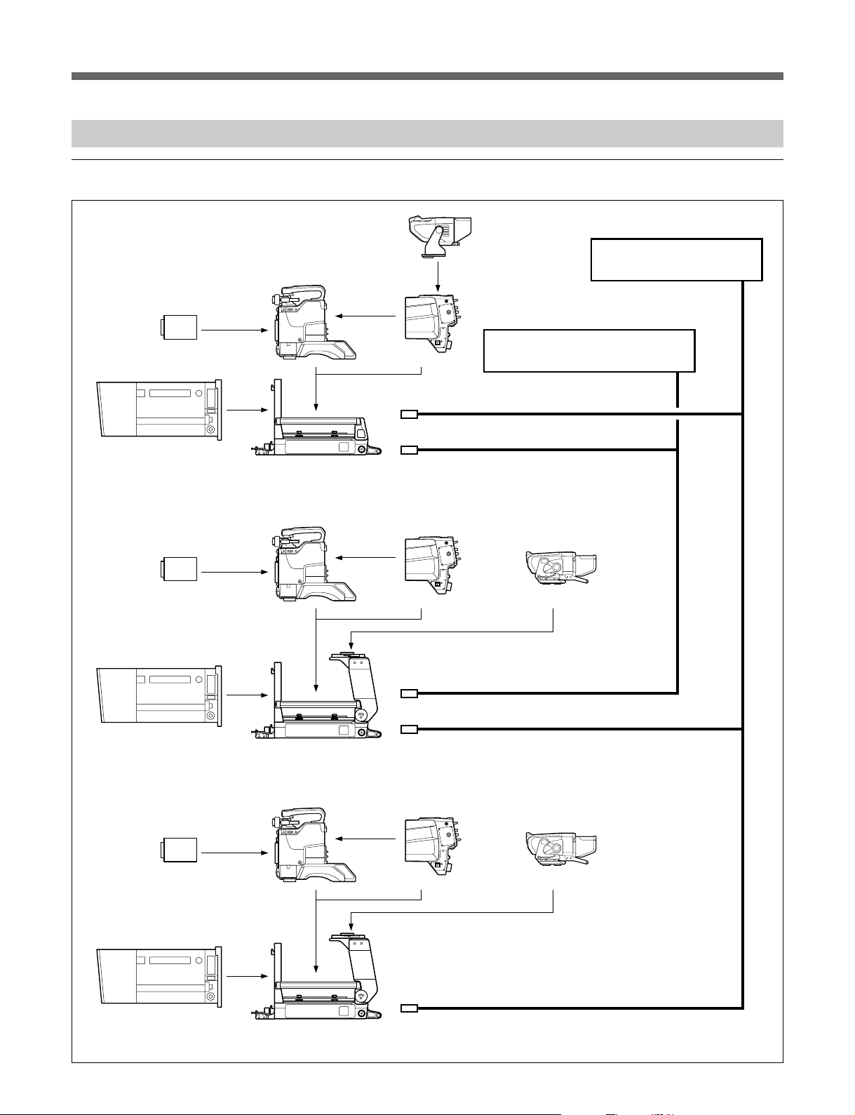
システム接続例
トライアックス伝送システム
カラービデオカメラ
BVP-550/950
ユニット
CCD
スタジオズームレンズ
8)
9)
型白黒ビューファイ
5
ンダー
BVF-55
カメラアダプター
CA-570
7) 9)
カメラコントロールユニット
CCU-550A
3) 4) 5) 6)
カメラコントロールユニット
CCU-700A
ユニット
CCD
スタジオズームレンズ
ユニット
CCD
トライアックスケーブル
トライアックスケーブル
CA-905K/905F/905T
カラービデオカメラ
BVP-550/950
8)
9)
CA-905K/905F/905T
カラービデオカメラ
BVP-550/950
8)
5)
カメラアダプター
CA-570
5)
+ BKP-9057
カメラアダプター
CA-570
型白黒ビューファイン
7) 9)
ビューファインダーサドル
7
ダー
7
7) 9)
ダー
1)
2)
BVF-77
型カラービューファイン
BVF-7700
スタジオズームレンズ
6 (J)
9)
CA-905K/905F/905T 5)+ BKP-9057
システム接続例(トライアックス伝送システム)
ビューファインダーサドル
Page 9

ファイバー伝送システム・
カラービデオカメラ
BVP-9500WS
ユニット
CCD
方式の場合
525
カラービデオカメラ
BVP-550/950
8)
型白黒ビューファインダー
5
カメラアダプター
CA-950
BVF-55
CCD
スタジオズームレンズ
カラービデオカメラ
BVP-9500WS
カラービデオカメラ
BVP-550/950
8)
ユニット
CA-905L
カメラアダプター
CA-950
ファイバーケーブル
型ビューファインダー
7
BVF-77/7700
10)
スタジオズームレンズ
コマンドネットワークユニット
マスターセットアップユニット
リモートコントロールパネル
システム接続例(ファイバー伝送システム・
CA-905L + BKP-9057
接続ケーブル
CCA-5
カメラコントロール
ユニット
ビューファインダーサドル
CCU-900
方式の場合)
525
7 (J)
Page 10
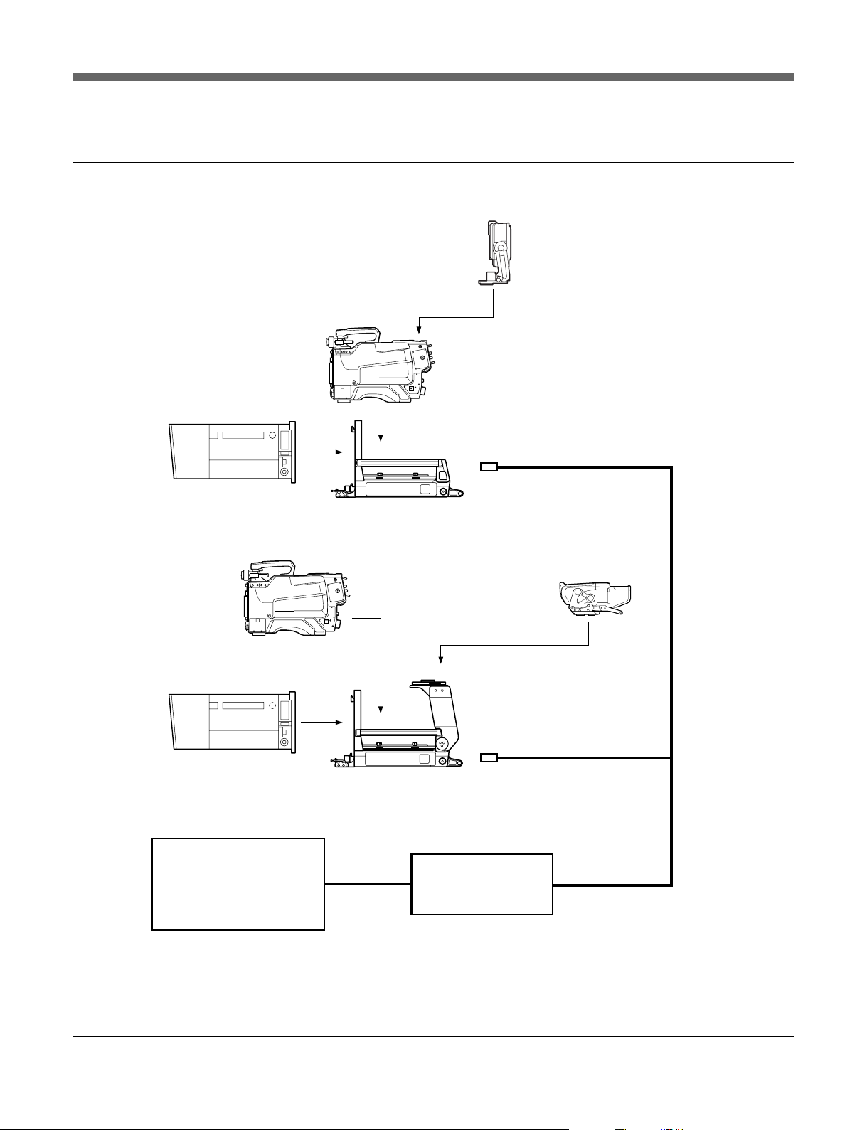
ファイバー伝送システム・
HDTV
方式の場合
スタジオズームレンズ
カラービデオカメラ
HD
HDC-950
カラービデオカメラ
HD
HDC-950
CA-905L
ビューファインダー
ファイバーケーブル
ビューファインダー
HDVF-700A/C700W
HDVF-C750W
10)
8 (J)
スタジオズームレンズ
コマンドネットワークユニット
マスターセットアップユニット
リモートコントロールパネル
システム接続例(ファイバー伝送システム・
CA-905L + BKP-9057
接続ケーブル
CCA-5
カメラコントロール
HD
ユニット
ビューファインダーサドル
HDCU-900
放送方式の場合)
HDTV
Page 11
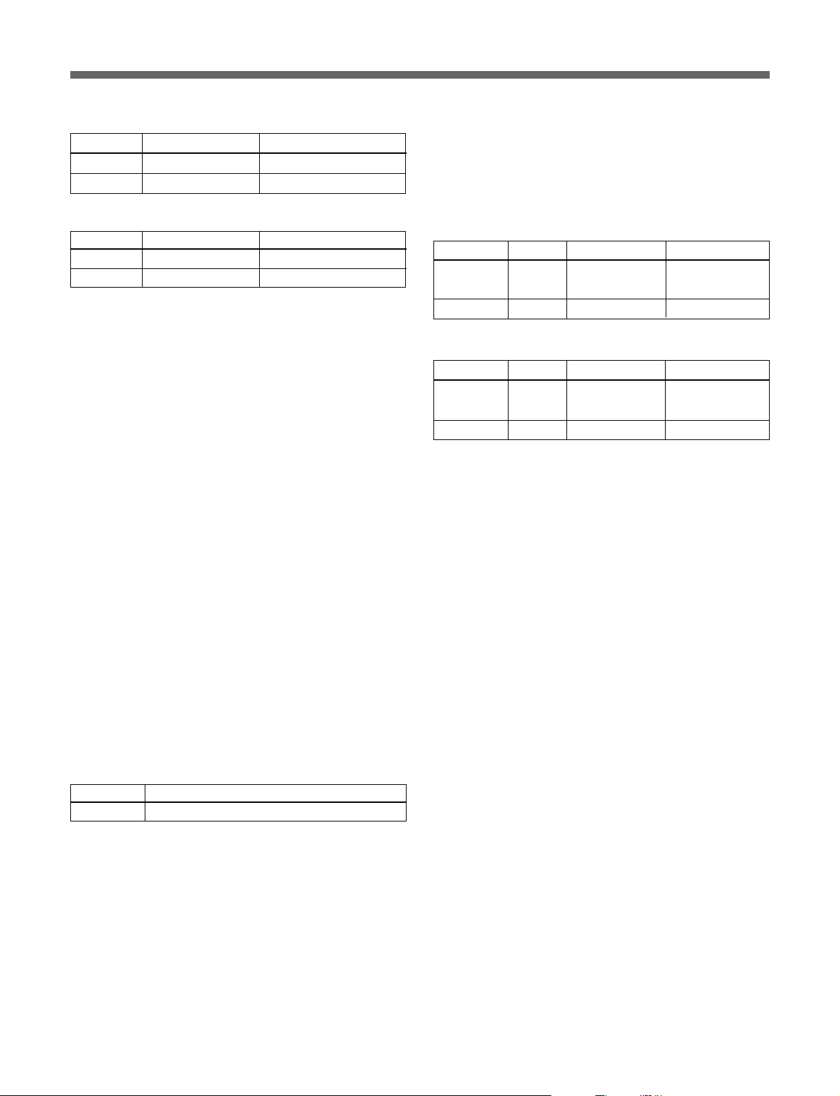
1)トライアックスケーブル長(CCU-700A)
直径 延長可能な長さ プロンプター信号到達距離
8.5mm 1000m 500m
14.5mm 2000m 1000m
バージョンのチェック
ROM
カメラ接続時、接続されているカメラに対応するそれぞれのATボードの
ROMバージョンを必 ずチェック してく ださい。
ROMバージョンが下の表と異なる場合、必ず対応したROMに入れ替えて
ください。
2)トライアックスケーブル長(CCU-550A)
直径 延長可能な長さ プロンプター信号到達距離
8.5mm 700m 500m
14.5mm 1400m 1000m
3)CCU-550AはCA-905Tに対応していますが、CCU-550は対応していま
せん。CCU-550は使用しないでください。
CCU-550を接続するためには 、CCUアップグレードユニットBKP-5976
での改造が必要です。
4)CCU-550AにDCパワーユニットBKP-5974を組み込んだ場合、CA-905T
には使用できません。CA-905T接続時は、BKP-5974を組み込んだ
CCU-550Aを使用しないでください。
5)CCU-550Aを接続時は、ビューファインダーBVF-7700は使用できませ
ん。ビューファインダーBVF-7700を使用するときは、CCU-700Aを使用
してく ださい。
6)CA-570とCCU-550Aを接続して使用するときには、インカムの伝送チャ
ンネルは1系統しか使用できません。CA-570のINCOM1コネクターを使
用してく ださい。
7)CA-550はCA-905Tには、対応していません。CA-905Tを使用するときに
は、CA-570を接続してください。
トライアックス伝送システムの場合
カメラ 基板名 リファレンス
BVP-950
BVP-550
AT-121 IC8 バージョン1.30以上
IC9 バージョン1.30以上
AT-95 IC36 バージョン4.20以上
No. ROM
バージョン
ファイバー伝送システムの場合
カメラ 基板名 リファレンス
BVP-950 AT-121 IC8 バージョン1.30以上
IC9 バージョン1.30以上
BVP-550 バージョン4.20以上AT-95 IC36
No. ROM
バージョン
8)電動サ ーボフィルターユニット内蔵でないCCDユニットをお選びの場合
は別売り電動サーボ フィルターユニット またはフ ィルターサーボ内蔵タイプ
のCCDユニットをご使用く ださい。
9)ス タジオズームレン ズのズームデマ ンド上のインカムマイ クスイ ッチを使 用
する と き は、CA-950、CA-570およびHDC-950のリアパネルのインカムマ
イ クスイッチをOFF(中央の位置)に合わせてください。
10)ファイバーケーブル長
直径 延長可能な長さ
9.5mm 2000m
9 (J)
Page 12
各部の名称と働き
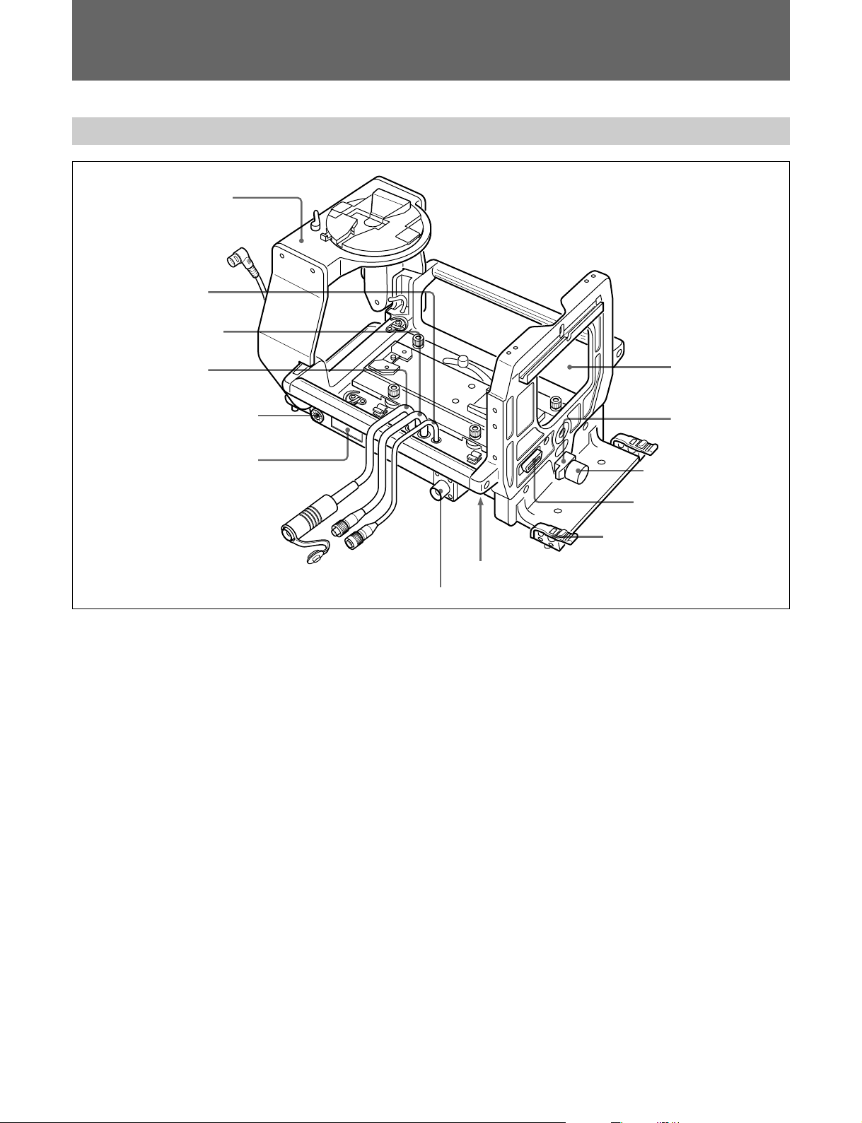
レンズ接合部(前面)と端子部
ビューファインダーサドル
BKP-9057
(別売り)
qa レンズケーブル
0
REMOTE
9
CA
8 アクセサリー取り付け金具
7 ナンバープレートホルダー
1
レンズロック
レンズの下端を押さえてレンズを固定します。
レンズロック固定つまみ
2
レンズロックを固定します。締めるときは時計回りに、ゆるめる と き
は反時計回りに回します。
ケーブル
ケーブル
レンズ口
1 レンズロック
2
レンズロック固定つまみ
3 レンズ端子
4
ケーブルクランプ
5レンズモード切り換えスイッチ
6
端子
CCU
6
トライア ッ ク スケーブルまたはフ ァイバーケーブル(別売り)で、カメ
ラコン ト ロールユニットのCAMERA端子に接続します。
7
付属のナンバープレートを取り付けま す。
(カメラコントロールユニット)端子
CCU
ナンバープレートホルダー
レンズ端子(36ピン)
3
レンズのコネクターに接続します。
ケーブルクランプ
4
カメラケーブルを固定します。直径8〜15mmのケーブルに対応
していま す。
◆ ケーブルクラン プの使いかたについては、システムマニュアルをご覧く
ださい。
5
レンズモード切り換えスイッチ
レンズの通信モードに合わせて切り換えます。
通常はNORMAL側にしてください。
シリアル通信対応レンズをご使用の場合は、SERIAL側に切り換え
てく ださい。
10 (J)
アクセサリー取り付け金具
8
別売りのスク リプトホルダーBKP-7911/7912などのアクセサリーを、
必要に応 じて取 り付けます。
◆ 取り付け方法については 、取り付けるアクセサリーの取扱説明書をご覧
く ださい。
9
(カメラアダプター)ケーブル(
CA
トライアックスコネクター、
バーコネクター)
カメラアダプターの CCU 端子に接続します。
q;
REMOTE
カメラアダプターのREMOTE端子に接続します。
qa
LENS
カメラのLENS端子に接続します。
(リモート)ケーブル(8ピン)
(レンズ)ケーブル(12ピン)
CA-905L:LEMO
CA-905T:
多治見型
型ファイ
Page 13
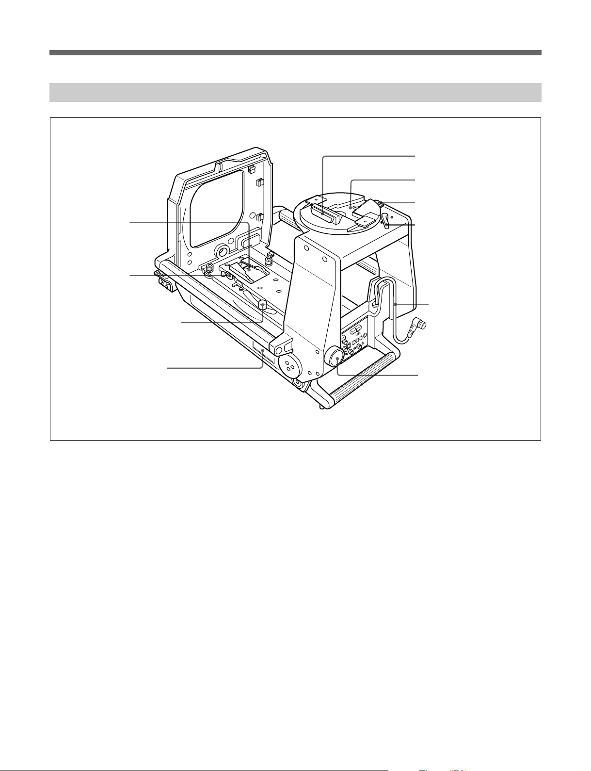
カメラ取り付け部(内部底面)と別売りビューファインダーサドル
q;
カメラマウント
9 カメラマウント
リリースレバー
8
カメラマウントスライドレバー
7
ナンバープレートホルダー
BKP-9057
1
端子
VF
2
ビューファインダーマウント
3
ビューファインダー
リリースボタン
4
パンロックレバー
5
接続ケーブル
VF
6
サドル固定つまみ
1
(ビューファインダー)端子
VF
ビュー ファ インダーのカメ ラ端子と接続します。
2
ビューファインダーマウント
ビュー ファ インダーを取り付けます。
3
ビューファインダーリリースボタン
ビュー ファ インダーを取り外すときに押します。
4
パンロックレバー
ビューフ ァインダーの回転を固定します。締めるときは反時計回り
に、ゆるめるときは時計回りに動かします。
接続ケーブル(
5
VF
カメラのVF端子(20ピン)に接続します。
6
サドル固定つまみ
サドルが倒れな いように固定 しま す。締めるときは右に 、ゆるめ る と
きは左に 回します。
BKP-9057
に付属)(
20
ピン)
ナンバープレートホルダー
7
付属のナンバープレートを取り付けま す。
8
カメラマウントスライドレバー
カメ ラマウン トを前後にス ライドさせます 。
9
カメラマウントリリースレバー
カメ ラを外 すとき、リリース レバーの左にあるセー フティーレバー を右
に押しながら押し込みます。
カメラマウント
q;
カメラ を取り付けます。前後に移動します。
11 (J)
Page 14
各部の名称と働き
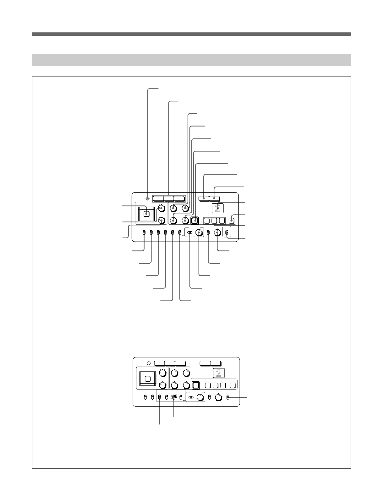
後面コントロールパネル
CA-905K/905F/905T
CA-905L(CA-950
および
使用時のみ)
右図はPinPスイッチ 用 ファンクション
ラベルを貼った状態です。
wh
FILTER LOCAL
wg
フィルターつまみ
ND
wf
フィルターつまみ
CC
wd
CENTER MARKER
ws
SAFETY ZONE
ボタン
スイッチ
スイッチ
POWER
FILTER LOCAL
CENTER
MARKER
ON
OFF
1
POWER
RGB RET RET 1
3 H-POSI
2
4
5
1
ND
C
B
D
E
A
CC
SAFETY
ZONE
UP TALLY
MIX VF
ON
ON
ON
OFF
OFF
OFF
(電源)インジケーター
2
ビデオ信号切り換えボタン
V-POSI
WIDTH
HEIGHT STORE
DISPLAY MENU SELECT
ON
OFF
ENTERCANCEL
MENU
3
H-POSI
4
1 2 3 ON
VF DETAIL PInP
ON
OFF
調整つまみ
V-POSI
5
WIDTH
6
HEIGHT
CORSOR
POSITION
ON
OFF
qg
VF DETAIL
調整つまみ
調整つまみ
調整つまみ
7
CURSOR STORE
8
ボタン
RET
9
RET 1
0
バックタリーランプ
qa
CURSOR ON
qs
CURSOR 1〜3
qd
qf
VF DETAIL
PinP
スイッチ
調整つまみ
スイッチ
ボタン
ボタン
ボタン
ボタン
(BKP-9057
組み込み時
)
CA-905L(HDC-950
wa
MIX VF
w;
UP TALLY
使用時のみ)
スイッチ
スイッチ
ql
予備スイッチ
下図はHDC用リアパネルシートを貼った状態です。
POWER
FILTER LOCAL
ND
CC
SAFETY
CENTER
ZONE
MARKER
ON
ON
OFF
OFF
wj
qh
qj
MENU SELECT
qk
DISPLAY
RGB RET RET 1
3 H-POSI
2
4
1
C
B
D
A
VF
TALLY
SCAN
16:9
4:3
VF SCAN
V-POSI
5
WIDTH
HEIGHT STORE
E
UP
SCREEN
SIZE
DISPLAY MENU SELECT
ON
ON
MARKER
ON
OFF
OFF OFF
MENU
wk
SCREEN SIZE MARKER
ENTERCANCEL
1 2 3 ON
VF DETAIL
ON
OFF
スイッチ
MENU SELECT
スイッチ
スイッチ
CORSOR
wl
スイッチ
つまみ
アサイナブルスイッチ
12 (J)
Page 15

ご注意
HDC-950使用時は、CA-905Lに付属のHDリアパネルシ ートを貼っ
てく ださい。
◆シート を貼る場所については、 23 ページをご覧く ださい。
1
POWER
カメラへの電源供給の状態により、次のように点灯します。
緑色:カメラに電源が供給されている とき。
オレンジ色:カメ ラの電源は供 給されているが、MSU-700または
RCP-700シリーズのVFPW ボタンが OFFになってい て、
ビュー ファ インダーに電源が供給されていないとき。
消灯:カメラに電源が供給されていないとき。
ビデオ信号切り換えボタン
2
ビューフ ァイ ンダーへのビデオ出力信号(R、G、B)を切り 換え ま
す。
R、G、Bいずれのボタンも押さない場合、出力信号は次のようにな
ります 。
白黒ビューファインダー使用時:ビュー ファ インダーにY 信号
が出力されます。
カラービューファインダー使用時:ビュー ファ インダーには、
R、G、B 信号が送られ、カ ラー画像を表示します。
(電源)インジケーター
8
このボタン を押し込むと、CA-950/570またはHDC-950で選択した
リターンビデオ2、3、4いずれかの信号をビューファイン ダーの画面
で見る こ と ができ ます。 再度ボタン を押すと、カメラの映像信号に
戻り ます。
9
このボタンを押し込 むと、 リ ターンビデオ1の信号をビューファイン
ダーの画面で見ることができます。再度ボタンを押すと、カメラの
映像信号に戻ります。
0
レッ ドタリー信号が供給 さ れていると き 点灯し ます。MSU-700および
RCP-700シリーズのCALLボタンを押すと、ランプ消灯時は点 灯
し、ランプ点灯時は消灯します。
付属のナンバープレートを取り付けて使用 します。
◆ ナンバープレートの取り付けかたについて は、23ページをご覧ください。
qa
このボタン を押すと点灯し、ボックスカーソルがビューフ ァイ ンダー
の画面上に表示 されます。再度押す と消灯し、カーソル が消えま
す。
(リターンビデオ選択)ボタン
RET
RET 1
CURSOR ON
(リターンビデオ1)ボタン
バックタリーランプ
(カーソル)ボタン
3
H-POSI
ビュー ファ イン ダ ーの画面上に表示されるボック スカーソルの 水平方
向の位置を調整します。
4
V-POSI
ビュー ファ イン ダ ーの画面上に表示されるボック スカーソルの 垂直方
向の位置を調整します。
5
WIDTH
ビュー ファ インダーの画面上に表 示されるボックスカーソルの幅を調
整します。
6
HEIGHT
ビュー ファ インダーの画面上に表示されるボックスカーソルの高さ を
調整します。
7
CURSOR STORE
H-POSI、V-POSI、WIDTH、HEIGHT調整つまみで調整したボッ
クスカーソルの大きさ と位置を登録する と き、このボタン を押します。
ご注意
CURSORONボタンが点灯していないときは、登録できません。
(水平位置)調整つまみ
(水平位置)調整つまみ
(幅)調整つまみ
(高さ)調整つまみ
(カーソルストア)ボタン
qs
CURSOR
ビュ ー ファ インダーの画面上に表示されるボックスカーソルの大き さ
と位置を呼び出し/登録します。1〜3のボ タンを使って3 種類の
設定を登録できます。ボタ ンを押すだけで、登録した大きさのボッ
クスカーソルを登録した位置に表示させるこ とができます。
ご注意
CURSOR1〜 3ボタンが点灯しているときは、H-POSI、V-POSI、
WIDTH、HEIGHT調整つまみは動作しません。
qd
PinP
組み込み時のみ)
9057
ビュー ファ インダーの画面に子画面を出します。
POSITION
置が変わ ります。
:PinPモードになり ます。RET1、RET ボタ ンがいずれも押さ
ON
れていない場合、親画面はカメラの画像、子画面はリターン
ビデオの画 像になります 。子 画 面には、最 後に選 択され たリ
ターンビデオの信号 が表示されます。RET1、RETボタンを押
すと、親画面と子画面の画像が逆になります。
:子画面は表示されません。
OFF
なおこの表示以外に2つのモードが選べます。
◆詳しくはカメラのシステムマニュアルをご覧く ださ い。
(カーソルメモリー)1〜3ボタン
(ピクチャーインピクチャー)スイッチ (
:ONからこの位置へ押し上げるたびに子画面の位
BKP-
13 (J)
Page 16

各部の名称と働き
ご注意
PinPモード時に、同期のとれていないRET信号を選択すると、
•
子画面が乱れることがありますが故障ではありません。
PinPモード時の子画面にもマーカー、キャラクターが表示され
•
ます。
見づらい場合は、カメラメニューで親画面、子画面ともマー
カー、キャラクター表 示を 自 動 的に 消 す モ ードやマーカ ー 、キャ
ラクターON時には自動的にPinPをOFFにするモードを選ぶこ
とができ ます。
BVP-9500WSの3倍速モードでは動作しません。
•
HDC-950使用時には、このスイッチの機能は変わります(wlア
•
サイナブルス イッチ参照)。
qk
DISPLAY
ビュー ファ インダー画面内に、スイ ッチ類の設定や、自動調整の項
目、結果などを示すス テータ ス表示を出すとき 使い ま す。
:ステータス表示機能が働きます。
ON
OFF
MENU
◆ メ ニ ュ ー操作については、システ ムマニュ アル を ご覧 ください。
ql
予備スイッチ
HDC-950使用時には、このスイッチ の機能は 変 わります(wk
SCREENSIZEMARKERスイッチ参照)。
(ディスプレイ)スイッチ
:ステータス表示機能が働きません。
:表示項目や機能を設定するメニュー画面になります。
qf
VF DETAIL
まみ
VFDETAILスイッチが O Nのとき、ビュー ファ インダーの画像のデ ィ
テール量を調整します。カメラの出力には影響しません。
ご注意
ビューファインダーディ テール量調整機能は、リターンビデオ信号
•
およびピク チャ ー インピクチャーの子画面には働きません。
BVP-550使用時は動作しません。
•
BVP-9500WSの3倍速モードでは動作しません。
•
qg
VF DETAIL
:ビュー ファ インダー内の画像の輪郭を強調します。この位
ON
置にするとVFDETAIL調整つまみでディテール量を調整で
きます。
:輪郭強調機能がOFFになります。
OFF
ご注意
BVP-550使用時およびBVP-9500WSの3倍速モードでは動作しま
せん。
qh
MENU SELECT
ビューフ ァイ ンダー画面 に表示された メニュー項目の選択や設定値
の変更を行い ます。
(ビューファインダーディテール量)調整つ
(ビューファインダー輪郭補正)スイッチ
(メニュー選択)つまみ
w;
UP TALLY
レッ ドタ リー信号が供給されているとき、レンズタリーラン プ 、ビュー
ファインダーの外部タ リーランプなどを点灯させるかどうかを選択し
ます。
:タリーランプが点灯します。
ON
:タリーランプは点灯しません。
OFF
wa
MIX VF
RET1ボタンまたはRETボタンを押したときの、ビュー ファ インダー
の画像を選択しま す 。
:RET1ボタンまたはRETボタンを押すと、カメラの出力信号
ON
とリターンビデオ信 号 (リ ターンビ デオ 1またはリ ターンビ デオ
2信号)の合成信号を、ビュー ファインダー画面で見ることが
でき ます。合成比は、CCU-700A内部の調整つまみで調整で
きます。
◆詳しくは、 シス テムマニュアルをご覧ください。
:
OFF
またはリ ターンビデオ 2 信号の信 号 のみを見るこ とができます。
ご注意
CCU-550A接続時は動作しません。
•
HDC-950使用時には、このスイッチの機能は変わります(wj
•
VFSCANスイッチ参照)。
(アップタリー)スイッチ
(ミックスビューファインダー)スイッチ
RET1ボタンまたはRETボタンを押すと、リターンビ デオ 1
qj
MENU SELECT
ENTER
CANCEL
◆ メ ニ ュ ー操作については、システ ムマニュ アル を ご覧 ください。
:MENUSELECTつまみで選択したメニューやペー
ジを確定したり、設定値を確定します。
:メニュー設定の内容を取り消したり、ページ選択
モードやTOPメニューに戻します。
(メニュー選択)スイッチ
14 (J)
ws
SAFETY ZONE
:カメラで撮影している画面の90%の範囲を示す枠(セー
ON
フテ ィ ーゾーン) を、ビュー ファ インダー画面内に表示します。
:セーフテ ィ ーゾーンは表示されません。
OFF
カメ ラのメニューで、表示する範囲を画面の80%に切り換えること
もでき ます。
◆詳しくは、 シス テムマニュアルをご覧ください。
(セーフティーゾーン)スイッチ
Page 17

wd
CENTER MARKER
:ビューファインダー画面の中央を示す白十字(センター
ON
マーカ ー)を表示 します。
:センターマーカーは表 示されません。
OFF
センターマーカーの位置は、レンズに合わせて調整できます。調整
した位置を、レンズファイルに登 録しておく ことが できます。
◆詳しくは、 シス テムマニュアルをご覧ください。
wf
(色温度変換)フィルターつまみ
CC
FILTERLOCALボタン点灯時、被写体を照らしている光源に合わ
せて、このつまみでフ ィルター を切り 換えるこ とができます。
電動サーボフィルタ ー内蔵タイプのCCDユニットもしく は、別売リ電
動サーボフィルターをご使用ください。
◆選択できるフィルターについては、使用するカメラの取扱説明書をご覧
ください。
ご注意
OHB-451をご使用の場合動作しません。
フィルターつまみ
wg
ND
FILTERLOCALボタン点灯時、このつまみでNDフ ィルター を切り
換えるこ とができます。
電動サーボフィルター内蔵タイプのCCDユニットもしくは別 売り電 動
サーボフィルターをご使用ください。
◆ 選択できるNDフィルターについては、使用するカメラの取扱説明書を
ご覧ください。
(センターマーカー)スイッチ
wk
SCREEN SIZE MARKER
カー)スイッチ
スクリ ーンサイ ズマーカ ー表示を選びます。
ON(
ON(
OFF
wl
アサイナブルスイッチ
HDC-950のカメラメニュー設定により、特定の機能を割り当てられ
ます。
):映像表示部以外の部分が暗くなる。
):映像表示部マーカー(白い線)が表示される。
:映像表示部マーカーは表示されない。
(スクリーンサイズマー
wh
FILTER LOCAL
ボタン
押すと点灯し、CCフィルターつまみ、 および NDフ ィルターつまみ
で、色温度変換フィルター、NDフィルターの切り換えが可能になり
ます。再び押すと消灯し、 フィルターのコントロールがマスターセ ッ
トアップユニットまたはリ モート コン トロールパネルに移り ます。
上記のqdPinPスイッチ、 ql予備スイッチ、 waMIXVFスイッチの
機能は、CA-905LにHDC-950を組み合わせて使用した場合のみ、
以下のように変わります。この 3 つのスイッチ以外のボタン、スイッ
チ類の働きは、CA-905K/905F/905TおよびCA-905L(CA-950使
用時のみ)の場合と同じです。
wj
VF SCAN
ビュー ファ インダー画面の表示をコントロールします。
:ビュー ファ インダー画面の表示を16:9にする。
16:9
:ビュー ファ インダー画面の表示を4:3にする。
4:3
(フィルターローカルコントロール)
(ビューファインダースキャン)スイッチ
15 (J)
Page 18

カメラの組み込みと機材・付属品の取り付け
カメラの組み込みと機材・付属品の取り付け
三脚への取り付け
1 本機を水平で安定な台の上に、底面が見えるように横倒しに
起き ます。
2 Vウェッジシュー(三脚に付属)をネジ(三脚に付属)で本体
の底面に取り付けます。 Vウ ェッジシ ュ ーの取り付け位置には、
本機、カメ ラ、 ビュ ー ファ インダー、 スタジオレンズの総重量と
三脚の雲台の大きさを考 慮し て、 本機が三脚上で安定する位
置を選んでください。
本体後面
前脚
前脚
スタジオ用大型レンズの取り付け
1 レ ンズロ ッ ク固定つまみをゆるめ、 レンズロック を左に倒す。
前板
レンズロック
固定つまみ
レンズロック
ご注意
カメ ラマウン トが後ろに下がって いることを確 認してください。 前に
来ている状態では、レ ンズロ ッ クを倒すこ とはでき ません。
2 カメ ラ取り付け部の前板を取り外 す。
3 レンズ後面のピンを本機前面のU字溝に差し込み、レンズの
エッジを本機の突起部 に引っかける。
ピン
エッジ
ウェッジシュー
V
ご注意
お使いになる 雲台に よってはケーブルクランプ底面の前脚が干渉
する場合があり ます。その際は前脚を取り外してく ださい。
前脚の外しかた
3 本機を三脚の雲台に取り付けます。
字溝
U
突起部
4 レンズ後面を本機側に押しつけ、レンズロック 固定つまみを右
に回す。レンズロックが右に立 ち上がり、レンズ のツメをはさむ
状態になっているの を確認してからレンズロック固定つまみを
締め る。レンズロッ クが レ ンズのツメ をは さ んでいないと き は、
レンズロック固定つまみを左に回してゆるめ、やり直す。
16 (J)
レンズモード切り換えスイッチ ツメ
レンズロックとレンズロック固定つまみ
Page 19

ご注意
レンズID:Fは使用しないでください。 Fに設定されているレンズ
•
は、別のIDナンバーに変更してください。 IDの確認および変更
方法はレンズの取扱説明書をご覧ください。
シリアル通信対応レンズをご使用の際は、本機のレンズモード切
•
り換えスイ ッチをSERIAL側に設定することで、より多くのレンズ
情報をカメ ラに取り込むこと ができます。なお、NORMAL側に設
定されていても、通常通りご使用になれます。
5 レンズキャップを取り外す。
3
レンズ固 定レバーを上 方に 回して、レンズマウン トキャップを 外 す 。
レンズ固定レバー
レンズマウントキャップ
カメラの組み込み
本編ではBVP-950を例にとって説明します。BVP-550などではカ
メラの V F 端 子 、レンズ端子の位置が異なります。
準備
1 ビュ ー ファインダーサ ドルBKP-9057を取り付けているときは、
サドル固定つまみを左に回してゆるめ、サ ドルを後ろに倒す。
サドル固定つまみ
カメラマウントの位置合わせ
一度カメラマウントの位置合わせを行うと、同じ機種であれば、組
み込むたびに位置合わせをする必要はありません。
カメラマウント
リリースレバー
スライドレバー
高さ調整つまみ
と固定つまみ
1 スライドレバーをLOCK位置まで下げる。
2 1.5型ビューファインダーを取り外 す。
ビュー ファ インダー用スラ イド台は、手前に戻してください。
端子
VF
17 (J)
Page 20

カメラの組み込みと機材・付属品の取り付け
2 カメ ラ底面のVウェッジシューをカメラマウ ン トのV字溝には め、
ロッ クさ れ る 位置までカメラを前方にスライドする 。
カチッと音がして、ロッ クがかかったこと を確認してください。
カメラ
カメラマウント
3
BKP-9057を使用しない場合は、BVF-55またはHDVF-C750W
をカメラに取り付ける。
4 カメ ラマウントの固定つまみ(4か所)をゆるめ、高さ調整つま
み(4か所)をDOWN方向に回す。
固定つまみ
6 カメラのハン ドル を持ち、カメラの レンズマウ ントとレン ズ のマウ
ント接合部を合わせる。
レンズのマウント接合部
カメラのレンズマウント
7 カメ ラを持ったたま ま、レ ン ズ固定レバー を下方に回 して、カメ
ラをレンズに固定する。
高さ調整つまみ
5 台を押さえながら、ス ライドレバーをFORWARD側に引く。
ご注意
レンズロックがレンズ のツメをはさん でい な いと、スライ ドレバーを
FORWARD側に引 ききることができません 。この場合は、レンズ
ロ ックが レ ンズのツメをはさ む状態になっている か確認して くださ
い。
レンズ固定レバー
8 高さ調整つまみ(4か所)を、UP方向に自然に止まるところま
で回し、前2か所の固定つまみを回して固定する。
9
レ ン ズ固定レバーを上げ下げ し 、ス ム ーズに動 くことを確 認 する。
動きが堅いときは、後ろ2か所の高 さ調整つ まみを わず かに回
して調整してください。
10後ろ2か所の固定つまみを回し、高さ調整つまみを固定する。
高さ調整つまみの目盛り値をメモしておく と、複数のカメラを
取り替えて使用するとき、設定の目安になります。
18 (J)
Page 21

カメラの組み込み
初めてのカメラを組み込むときは、「カ メラ マ ウントの位置合わせ」
(17ページ)が必要です。
1 スライドレバーをLOCK位置まで下げる。
2 カメ ラ底面のVウェッジシューをカメラマウ ン トのV字溝には め、
ロッ クさ れ る 位置までカメラを前方にスライドする 。
カチッと音がして、ロッ クがかかっ たこ とを確認 してください。
5 レンズコネクターをカメラのLENS端子に接続する。
端子
LENS
レンズコネクター
6 台を押さえながら、ス ライドレバーをFORWARD側に引く。
カメラマウント
3 BKP-9057を使用しない場合は、BVF-55
をカメラに取り付ける。
4
BVF-55
BKP-9057
または
HDVF-C750W
HDVF-C750W
してください。
をカ メラ のVF 端子に接続 して ください。
の接続ケーブルをカメラのVF端子に接続
使用時:本機のビューファイン ダー接続ケー ブル
使用時: BVF-55
カメラ
またはHDVF-C750W
または
ご注意
レンズロックがレンズ のツメをはさん でい な いと、スライ ドレバーを
FORWARD側に引ききることができません。この場合は、レンズ
ロ ックが レ ンズのツメをはさ む状態になっている か確認して くださ
い。
7 レ ン ズ固定 レバー を下方に回して 、レンズを固定する。
レンズ固定レバー
19 (J)
Page 22

カメラの組み込みと機材・付属品の取り付け
8 ビュ ー ファインダーサ ドルBKP-9057を取り付けているときは、
サドルを起こし、サドル固定つまみを右に回して固定する。
サドル固定つまみ
9 リモートケーブ ルのコネクターを、本機後面のリモート端 子に接
続する。
本機のCAケーブルをカメラアダプターのCCU端子に接続す
る。
端子
CCU
4 VFコネクターとLENSコネクターを外す。
5 セーフティレバーを押しながら、リ リースレバーを押 して 、カメラ
を取り外す。
リリースレバーセーフティー
レバー
ご注意
カ メラを取り外した後、カメ ラマウント のピンが中央に残ったままだ
とカメ ラの取り付けができません。 その時は、もう一度 セーフティ ー
レバー を押 し ながらリリースレバーを押 し込んで ください。
ポータブルレンズの取り付け
リモート端子
ケーブル
CA
リモートケーブル
カメラの取り外しかた
ご注意
BKP-9057組み込み時は、まずビューフ ァインダーを取り外してく だ
さい。
◆ビューファインダー の取り外し方は、23 ページをご覧くださ い。
ビュー ファ インダーサ ドルBKP-9057組み込み時は、サドル固定つ
まみをゆるめて、 サドル を倒してください。
1 CAコネクタ ーと リモート ケーブルをカメ ラ アダプターか ら外す。
2 レンズ固定レバーを上げる。
3 スライドレバーをLOCK位置まで下げる。
使用できるレンズはエクステンダー内蔵タイプのものです。
マウント接合部レンズ口
ポータブルレンズ
フック
レンズ固定レバーレンズマウント
1「カメラの組み込み」(17ページ)を参照し 、カメラ を本機に組
み込む。スライドレバーを前に出し、フック をか け る。
2 本機前面のレンズ口から、ポータブ ルレンズ のマウン ト接合 部
を本機に入れ、カメラのレンズマウント に取り付ける。
ご注意
レ ンズは、スライドレバーをLOCK位置まで下げないと取り外
せません。
20 (J)
3 レンズ固定レバーを下に回し、固定する。
4 ポータ ブルレ ン ズのレ ンズコ ネク タ ー をレンズ口から 本機に通
し、カメラのLENS端子に接続する。
Page 23

BVF-55
または
HDVF-C750W
を取り付ける
カメラアダプターまたはカメラにBVF-55またはHDVF-C750Wを取
り付けるこ とが できます。
◆ビューファインダーの取り 付 け について詳しくは、ビュー ファ インダーの取
扱説明書も併せてご覧ください。
1 カメ ラアダプター上部のキャップまたはネジ4個を外す。
3
ビューフ ァインダー底面の Vウェ ッジシューを V ウェ ッジシューア
タ ッチメントに 差し 込 み、 ビュ ー ファ インダーをカメラに取り付ける。
カチッと音がして固定されます。
ウェッジシュー
V
アタッチメント
S
1000
Power HAD
MIC1
2 ビュー ファ インダーに付属のVウェ ッジシューアタッチメント をカ
メ ラアダプター部に取り付け、ビュー ファインダーに付属の六角
ボルトで固定する。
ウェッジシュー
V
アタッチメント
ウェッジシュー
V
S
Power HAD
MIC1
1000
4 ビューファ イ ンダーの接続ケーブルをカメラのVF端子に接続
する。
S
1000
Power HAD
MIC1
S
Power HAD
MIC1
1000
取り外すには
Vウェッジシューアタ ッチメ ン トのレバーを引き なが ら、ボタ ンを押し
て取り外します。
ボタン
レバー
S
1000
Power HAD
MIC1
21 (J)
Page 24

カメラの組み込みと機材・付属品の取り付け
ビューファインダーの取り付け(
9057
組み込み時)
BKP-
取り付けかた
ビュー ファ インダーの取り 付け について詳 し くは、ビュー ファ インダー
の取扱説明書も併せてご覧ください。
ご注意
ビュー ファ インダーを取り付ける前に、ビュー ファインダーサ ドルのパ
ンベース受け台のVF端子が時計回 しいっぱいになっていること を
確認してください。
1 ビュー ファ インダーのパンベース裏側にあるマウ ント ウェ ッジが、
BKP-9057のパンベース受け台のV字型溝の中に入るように、
また、 パンベース裏側の突起部が図に示す位置にくるように、
ビュー ファ インダ ーをパ ン ベ ース受け台にのせる。
マウントウェッジ突起部 パンベース
3 ビューフ ァイ ンダーを所定の位置まで回す。パン ロック レバーを
右に回すとビューファ イ ンダーマウントのパンニングをロッ クで
きます。
パンロックレバー
ご注意
ビュー ファ インダーは確実に固定してください。 正しく 取り付けられ
ていないと、 落下してけがの原因となること がありま す。
ビューファインダー
の底面
コネクター
VF
2 ロックされる位 置までビューファインダーをス ライドさせる。ロッ
ク されるとカチッと音がします。
22 (J)
Page 25

取り外しかた
ナンバープレートの取り付け
取り外す前に、次の2点を確認してください。
ビュー ファ インダーのリフト解除ノブが一番低い位置にあること。
•
ビューフ ァインダー のロックレバ ーが右いっぱいの位置に あること。
•
リフト解除ノブがこの位置にある。
左右の両端の突起をホルダーの溝に差 し込み、ナンバープレー ト ホ
ルダーに取り付けます。
ナンバープレート
2
ナンバープレートホルダー
用リアパネルシートの貼り付け
HDC
後面パネルの下図の位置に貼り付けます。
ロックレバーが右いっぱいの位置にある。
1 パンロックレバーを左に回し、パンベース受け台を時計方向
いっぱいに回転 させる。
この位置でないと、ビューフ ァイ ンダーは取り外せません。
2 ビュ ー ファ インダーリリースボタンを 押し な がら、ビ ューファイン
ダーの取っ手を左側に引き 、 持ち 上げて外す。
ビューファインダー
リリースボタン
パンロックレバー
UP
SCREEN
VF
TALLY
SIZE
SCAN
ON
16:9
MARKER
ON
OFF OFF
4:3
用リアパネルシート
HDC
DISPLAY
ON
OFF
MENU
23 (J)
Page 26

主な仕様
主な仕様
大型レンズアダプター
CA-905K/905F/
905T
一般
質量 12kg
外形寸法 368×327×534mm
動作温度 −20℃〜+45℃
保存温度 −20℃〜+55℃
消費電力 90W(大型レンズおよび7型カラービュー
ファインダー使用時、BKP-9057含む)
入出力端子/コネクター
CCU端子 多治見型トライ アッ クスコネクタ ー
レンズ端子 36ピン
LENSコネクター 12ピン
CAコネクター 多治見型トライ アックス コネクター
REMOTEコネクター 8ピン
付属品
ナンバープレー ト(2組)(サイドパネル用)
ナンバープレー ト(1組)(リアパネル用)
ケーブルクランプ(2)
オペ レーションマニュアル(1)
メンテナ ンス マニュアルパート1(1)
角度調整金具(2)
大型レンズアダプター
CA-905L
一般
質量 12kg
外形寸法 368×327×534mm
動作温度 −20℃〜+45℃
保存温度 −20℃〜+55℃
消費電力 90W(大型レンズおよび7型カラービュー
ファインダー使用時、BKP-9057含む)
入出力端子/コネクター
CCU端子 LEMO型ファイバーコネクター
レンズ端子 36ピン
LENSコネクター 12ピン
CAコネクター LEMO型ファイバーコネクター
REMOTEコネクター 8ピン
付属品
ナンバープレー ト(2組)(サイドパネル用)
ナンバープレー ト(1組)(リアパネル用)
ケーブルクランプ(2)
オペ レーションマニュアル(1)
メンテナ ンス マニュアルパート1(1)
角度調整金具(2)
HDC用リアパネルシート(1)
別売りアクセサリー
トライアックスケーブ ル
CCT-5T/10T/20T/50T/100T/150T/200T
7型白黒ビューファインダーBVF-77
7型カラービューファインダーBVF-7700(CCU-700A使用時)
5型白黒ビューファインダーBVF-55
24 (J)
別売りアクセサリー
7型白黒ビューファインダーHDVF-700A/BVF-77
7型カラービューファインダーBVF-7700(CCU-900使用時)
7型カラー液晶ビューファインダーHDVF-C750W/C700W
5型白黒ビューファインダーBVF-55
Page 27

ビューファインダーサドル
BKP-9057
一般
質量 2.3kg
外形寸法 368×373×534mm(CA-905T/905Lを含
み、ビュー ファ インダー含ま ず)
消費電力 90W(大型レンズおよび7型カラービュー
ファインダー使用時、CA-905T/905L
含む)
接続端子
VF端子 25ピン
カメ ラ端子 20ピン
仕様および外観は、改良のため予告なく変更することがあります
が、ご了承ください。
25 (J)
Page 28

English
WARNING
To prevent fire or shock hazard, do not
expose the unit to rain or moisture.
To avoid electrical shock, do not open the
cabinet. Refer servicing to qualified
personnel only.
VORSICHT
Um Feuergefahr und die Gefahr eines
elektrischen Schlages zu vermeiden, darf
das Gerät weder Regen noch Feuchtigkeit
ausgesetzt werden.
Um einen elektrischen Schlag zu
vermeiden, darf das Gehäuse nicht
geöffnet werden. Überlassen Sie
Wartungsarbeiten stets nur einem
Fachmann.
For the customers in the USA (CA-905K/905L, BKP-9057)
This equipment has been tested and found to comply with
the limits for a Class A digital device, pursuant to Part 15 of
the FCC Rules. These limits are designed to provide
reasonable protection against harmful interference when the
equipment is operated in a commercial environment. This
equipment generates, uses, and can radiate radio frequency
energy and, if not installed and used in accordance with the
instruction manual, may cause harmful interference to radio
communications. Operation of this equipment in a residential
area is likely to cause harmful interference in which case the
user will be required to correct the interference at his own
expense.
You are cautioned that any changes or modifications not
expressly approved in this manual could void your authority
to operate this equipment.
The shielded interface cable recommended in this manual
must be used with this equipment in order to comply with the
limits for a digital device pursuant to Subpart B of Part 15 of
FCC Rules.
For the customers in Europe (CA-905F/905L, BKP-9057)
This product with the CE marking complies with both the
EMC Directive (89/336/EEC) and the Low Voltage Directive
(73/23/EEC) issued by the Commission of the European
Community.
Compliance with these directives implies conformity to the
following European standards:
• EN60950: Product Safety
• EN55103-1: Electromagnetic Interference (Emission)
• EN55103-2: Electromagnetic Susceptibility (Immunity)
This product is intended for use in the following
Electromagnetic Environment(s):
E1 (residential), E2 (commercial and light industrial),
E3 (urban outdoors) and E4 (controlled EMC environment,
ex. TV studio)
Für Kunden in Europa (CA-905F/905L, BKP-9057)
Dieses Produkt besitzt die CE-Kennzeichnung und erfüllt
sowohl die EMV-Direktive (89/336/EEC) als auch die
Direktive Niederspannung (73/23/EEC) der EG-Kommission.
Die Erfüllung dieser Direktiven bedeutet Konformität für die
folgenden Europäischen Normen:
• EN60950: Produktsicherheit
• EN55103-1: Elektromagnetische Interferenz (Emission)
• EN55103-2: Elektromagnetische Empfindlichkeit
(Immunität)
Dieses Produkt ist für den Einsatz unter folgenden
elektromagnetischen Bedingungen ausgelegt:
E1 (Wohnbereich), E2 (kommerzieller und in beschränktem
Maße industrieller Bereich), E3 (Stadtbereich im Freien) und
E4 (kontrollierter EMV-Bereich, z.B. Fernsehstudio).
Pour les clients européens (CA-905F/905L, BKP-9057)
Ce produit portant la marque CE est conforme à la fois à la
Directive sur la compatibilité électromagnétique (EMC) (89/
336/CEE) et à la Directive sur les basses tensions (73/23/
CEE) émises par la Commission de la Commùnauté
européenne.
La conformité à ces directives implique la conformité aux
normes européennes suivantes:
• EN60950: Sécurité des produits
• EN55103-1: Interférences électromagnétiques (émission)
• EN55103-2: Sensibilité électromagnétique (immunité)
Ce produit est prévu pour être utilisé dans les
environnements électromagnétiques suivants:
E1 (résidentiel), E2 (commercial et industrie légère),
E3 (urbain extérieur) et E4 (environnement EMC contrôlé ex.
studio de télévision).
Page 29

Table of Contents
English
Overview............................................................................................... 2(E)
Features ...........................................................................................2(E)
Studio camera system configuration ...............................................3(E)
Location and Function of Parts.......................................................... 7(E)
Lens Attachment Section (Front) and Connectors ..........................7(E)
Camera-mounting Section (Inner Base) and the Optional BKP-9057
Viewfinder Saddle.................................................................8(E)
Rear control panel ...........................................................................9(E)
Fitting the Camera, Equipment and Accessories ........................... 13(E)
Tripod Mounting ...........................................................................13(E)
Attaching a Large-lens for Studio Use ..........................................13(E)
Attaching the Camera....................................................................14(E)
Attaching a portable lens...............................................................17(E)
Attaching a viewfinder (When the BKP-9057 is installed)...........19(E)
Attaching the number plates..........................................................20(E)
Attaching the rear-panel sticker ....................................................20(E)
Specifications...................................................................................... 21(E)
CA-905F/905K Large Lens Adaptor.............................................21(E)
CA-905L Large Lens Adaptor ......................................................21(E)
BKP-9057 Viewfinder Saddle.......................................................22(E)
1(E)
Page 30

Overview
The CA-905K/905F/905L Large Lens Adaptor enables
the attachment of a studio lens to a portable color
video camera (referred herein as “camera”). The CA905K/905F is designed for use on a camera that is
connected to a CA-570/570P Camera Adaptor for
Triax transmission. The CA-905L is designed for use
on a camera that is connected to a CA-950/950P
Camera Adaptor for optical-fiber transmission or on
the HDC-950 HD Portable Camera. The CA-905K/
905F/905L accepts the attachment of an optional 5type viewfinder, or an optional 7-type viewfinder
when the optional BKP-9057 Viewfinder Saddle is
used.
Features
Compatible with Sony specification Large
-lens
The unit allows you to attach Sony hanger-type largelenses. It is compatible with both full servo-control
and manual control lenses. You can also use a
portable lens (with extender only).
Seven-type viewfinder (available when the
BKP-9057 is installed)
By installing the optional BKP-9057 viewfinder saddle
to the unit, you can use a 7-type B/W viewfinder and a
7-type color viewfinder.
Note
When the CCU-550A/550AP is connected, the BVF7700/7700P cannot be used.
Studio-use-camera-type control panel
The rear control panel provides almost all the
functions of the color video camera for studio use. It
thus allows you to operate the unit (when used to
connect a large lens to the camera) as you would a
studio camera.
By installing the BKP-9057, the Picture-In-Picture
function can also be used. Note, however, that the
Picture-In-Picture function cannot be used with certain
cameras.
Easy to assemble and disassemble
Once you have done the initial lens and camera
alignment, you need not repeat the alignment each
time you attach the lens and camera. The BKP-9057
employs a saddle rotation function which makes it
easy to attach and detach the camera.
Lightweight and space-saving system
The CCU-550A/550AP (portable CCU) enables the
use of a large lens (only when the CA-950K/905F is
used). Further savings in weight and space is possible
by using a 5-type viewfinder.
2 (E)
Page 31

Studio camera system configuration
Triax transmission system
BVP-550/570/950/950P
Color Video Camera
BVF-55/55CE 5-type
monochrome viewfinder
CCU-700A/700AP Camera
Control Unit
CCD unit
STUDIO ZOOM LENS
CCD unit
STUDIO ZOOM LENS
8)
9)
CA-905K/905F Large
Lens Adaptor
BVP-550/570/950/950P
Color Video Camera
8)
9)
5)
CA-570/570P
Camera Adaptor
CA-570/570P
Camera Adaptor
7) 9)
CCU-550A/550AP
Camera Control Unit
TRIAX CABLE
TRIAX CABLE
BVF-77/77CE
7) 9)
7-type monochrome viewfinder
1)
2)
3) 4) 5) 6)
CCD unit
STUDIO ZOOM LENS
CA-905K/905F Large Lens
5)
Adaptor
BVP-550/570/950/950P
Color Video Camera
8)
9)
CA-905K/905F Large
Lens Adaptor
Studio camera system configuration (Triax transmission system)
5)
+ BKP-9057
Viewfinder Saddle
CA-570/570P
Camera Adaptor
+ BKP-9057
Viewfinder Saddle
BVF-7700/7700P
7) 9)
7-type color viewfinder
3 (E)
Page 32

Optical fiber transmission system (for 525/625 broadcasting)
BVP-9500WS/9500WSP
Color Video Camera
BVP-550/570/950/950P
Color Video Camera
BVF-55/55CE 5-type
monochrome
viewfinder
CA-950/950P
Camera Adaptor
CCD unit
8)
STUDIO ZOOM LENS
BVP-9500WS/9500WSP
Color Video Camera
BVP-550/570/950/950P
Color Video Camera
CCD unit
8)
CA-905L Large
Lens Adaptor
CA-950/950P
Camera Adaptor
Fiber cable
10)
BVF-77/77CE/7700/7700P
7-type viewfinder
4 (E)
STUDIO ZOOM LENS
CA-905L Large Lens Adaptor
+ BKP-9057 Viewfinder Saddle
Command Network Unit
Master Setup Unit
CCA-5
Connecting
Cable
CCU-900/900P Camera
Control Unit
Remote Control Unit
Studio camera system configuration (optical fiber transmission system for 525/625 broadcasting)
Page 33

Optical fiber transmission system (for HDTV broadcasting)
HDVF-C750W
6-type Color LCD
Viewfinder
HDC-950 HD Color
Video Camera
STUDIO ZOOM LENS
HDC-950 HD Color
Video Camera
STUDIO ZOOM LENS
Command Network Unit
Master Setup Unit
Remote Control Unit
CA-905L Large
Lens Adaptor
CA-905L Large Lens Adaptor
CCA-5
Connecting
Cable
+ BKP-9057 Viewfinder Saddle
HDCU-900 HD Camera
Control Unit
Fiber cable
HDVF-700A 7-type
Monochrome Viewfinder/
HDVF-C700W 6-type Color
LCD Viewfinder
10)
Studio camera system configuration (optical fiber transmission system for HDTV broadcasting)
5 (E)
Page 34

1) TRIAX cable (CCU-700A/700AP) length
Diameter Maximum length
8.5 mm 1000 m 500 m
14.5 mm 2000m 1000m
Maximum distance for
prompter signal transmission
2) TRIAX cable (CCU-550A/550AP) length
Diameter Maximum length
8.5 mm 700 m 500 m
14.5 mm 1400m 1000m
Maximum distance for
prompter signal transmission
3) The CCU-550A/550AP is compatible with the CA-905K/
F, not the CCU-550/550P. The CCU-550/550P therefore
cannot be used with the CA-905K/F.
To connect the CCU-550/550P, you must first attach the
BKP-5976 CCU upgrade unit to the CCU-550/550P.
4) When the BKP-5974 has been equipped with the CCU550A/550AP DC power unit, the CA-905K/F cannot be
used. For this reason, when the CA-905K/F is connected,
do not use the CCU-550A/550AP with the BKP-5974.
5) When the CCU-550A/550AP is connected to the unit, the
BVF-7700/7700P cannot be used.
When you connect the BVF-7700/7700P to the unit, use
the CCU-700A/700AP.
6) When the CA-570/570P is connected to the CCU-550A/
550AP, only one channel can be used for intercom
transmission. Use the INCOM1 connector on the CA570/570P.
CAUTION
Do not use a defective triaxial cable.
The inner sheath of a triaxial cable is used for power
supply and the outer sheath for safety ground.
For your safety, do not use a triaxial cable whole inner
and outer sheaths are short-circuited. Use of such a
cable will cause electric shock.
Check of ROM Version
When connecting the camera, be sure to check the
version of ROM on each AT board corresponding to
the camera to be connected.
If ROM version differ from the below table, be sure to
perform ROM replacement.
If ROM replacement is required, contact your local
Sony Sales Office/Service Center.
When Triax transmission system is used
Camera Board name Ref No. ROM version
BVP-950/950P/
950WSPK
BVP-550 AT-95 IC36 Ver.4.20 or higher
BVP-570/ AT-126 IC36 Ver.1.30 or higher
570WSPK
AT-121 IC8 Ver.1.30 or higher
IC9 Ver.1.30 or higher
When fiber transmission system is used
Camera Board name Ref No. ROM version
BVP-950/950P/
950WSPK
BVP-550 AT-95 IC36 Ver.4.20 or higher
AT-121 IC8 Ver.1.30 or higher
IC9 Ver.1.30 or higher
7) The CA-550/550P is not compatible with the CA-905K/F.
To use the CA-905K/F, you must first connect the CA570/570P.
8) If you selected a CCD unit which does not have an
electric servo filter unit, use an optional electric servo
filter with your CCD or a CCD with a built-in servo filter.
9) When you use the intercom microphone switch located on
the zoom demand of the studio zoom lens, be sure to set
the intercom microphone switch of the CA-950/950P/570/
570P or HDC-950 to OFF (center position).
10) Fiber cable length
Diameter Maximum length
9.5 mm 2000 m
6 (E)
Page 35

Location and Function of Parts
Lens Attachment Section (Front) and Connectors
BKP-9057 Viewfinder
Saddle (not supplied)
qa Lens cable
q; REMOTE cable
9 CA cable
8 Accessory bracket
7 Number plate holder
1 Lens lock
Secures the lens by the tongue-like protrusion at the
lens bottom.
2 Lens lock holding knob
Secures the lens lock. Turn clockwise to tighten, and
counterclockwise to loosen.
3 Lens connector (36-pin)
Connect to the connector on the lens.
4 Cable clamp
Secures the camera cable. The diameter of the cable
with a diameter of 8 to 15 mm should be used with the
cable clamp.
Refer to System Manual for details on using the cable
clamp.
5 Lens mode switch
Selects one of the two lens communication modes.
During normal operation, set to NORMAL.
During use of a serial communication lens, set to
SERIAL.
Lens mouth
1 Lens lock
2 Lens lock
holding knob
3 Lens connector
4 Cable Clamp
5 Lens mode switch
6 CCU connector
6 CCU (camera control unit) connector (triax
connector: Kings type for the CA-905K, Fischer
type for the CA-905F; fiber connector: LEMO
type for the CA-905L)
Connects through a triax cable or fiber cable (not
supplied) to the CAMERA connector on the CCU550A/550AP/700A/700AP.
7 Number plate holder
Fit the supplied number plates.
8 Accessory bracket
Attach an optional accessory, such as a BKP-7911/
7912 Script Holder.
For attaching the accessory, refer to the instruction manual
supplied with the accessory.
9 CA (camera adaptor) cable (triax connector:
Kings type for the CA-905K, Fischer type for the
CA-905F; fiber connector: LEMO type for the CA905L)
Connect to the CCU connector on the camera adaptor.
q; REMOTE cable (8-pin)
Connect to the REMOTE connector on the camera
adaptor.
qa Lens connector (12-pin)
Connect to the LENS connector of the camera.
7 (E)
Page 36

Camera-mounting Section (Inner Base) and the Optional BKP-9057 Viewfinder Saddle
1 VF (viewfinder) connector
2 Viewfinder mount
3 Viewfinder release button
q; Camera mount
9 Camera mount
release lever
8 Camera mount
slide lever
7 Number holder
1 VF (viewfinder) connector
Connect to the camera connector on a viewfinder.
2 Viewfinder mount
Attach the viewfinder.
3 Viewfinder release button
Push this button to disengage the viewfinder
4 Pan-lock lever
Turn counterclockwise to tighten the viewfinder. Turn
clockwise to loosen the viewfinder.
5 VF connecting cable (supplied with the BKP-
9057) (20-pin)
Connects to the VF connector (20-pin) on the camera.
4 Pan-lock lever
5 VF connecting cable
6 Saddle lock knob
7 Number plate holder
Fit the supplied number plates.
8 Camera mount slide lever
Pull this lever to slide the camera mount forward and
backward.
9 Camera mount release lever
To remove the camera from the unit, push this lever
while pushing the safety lever (on the left) rightward.
q; Camera mount
Fit the camera. Slide to the front and rear.
6 Saddle lock knob
Locks the saddle so it does not topple down. Turn
counterclockwise to tighten the saddle, or clockwise to
loosen it.
8 (E)
Page 37

Rear control panel
CA-905K/905F or CA-905L (during use with the CA-950/950P only) with PinP switch
sticker attached
wh FILTER LOCAL button
wg ND filter control
wf CC filter control
POWER
FILTER LOCAL
1 POWER indicator
2 Video signal select buttons
RGB RET RET 1
3H-POSI
2
4
5
1
ND
WIDTH
C
B
D
E
A
CC
SAFETY
CENTER
MARKER
MIX VF
ZONE
ON
ON
ON
OFF
OFF
OFF
UP TALLY
ON
OFF
DISPLAY MENU SELECT
ON
OFF
MENU
3 H-POSI control
V-POSI
HEIGHT STORE
ENTERCANCEL
4 V-POSI control
5 WIDTH control
6 HEIGHT control
7 CURSOR STORE button
8 RET button
CORSOR
1 2 3 ON
VF DETAIL PInP
ON
POSITION
ON
OFF
OFF
9 RET 1 button
0 Back tally lamp
qa CURSOR ON button
qs CURSOR 1, 2, and 3 buttons
qd PinP switch (when the BKP-9057 is installed)
wd CENTER MARKER switch
ws SAFETY ZONE switch
wa MIX VF switch
w; UP TALLY switch
ql Spare switch
qj MENU SELECT switch
qk DISPLAY switch
qf VF DETAIL control
qg VF DETAIL switch
qh MENU SELECT knob
CA-905L (during use with the HDC-950 only) with rear-panel sticker attached
POWER
RGB RET RET 1
3H-POSI
2
SAFETY
4
5
1
ND
WIDTH
C
B
D
E
A
CC
UP
SCREEN
VF
TALLY
SIZE
SCAN
ZONE
ON
16:9
ON
OFF
MARKER
ON
OFF OFF
4:3
FILTER LOCAL
CENTER
MARKER
ON
OFF
wk SCREEN SIZE MARKER switch
wj VF SCAN switch
V-POSI
HEIGHT STORE
DISPLAY MENU SELECT
ON
OFF
ENTERCANCEL
MENU
CORSOR
1 2 3 ON
VF DETAIL
ON
OFF
wl Assignable switch
9 (E)
Page 38

Location and Function of Parts
Note
When the HDC-950 is used, be sure to attach the rearpanel sticker (supplied with the CA-950L) to the rear
panel of the camera. For details regarding the sticker
position, see page 20.
1 POWER indicator
Lights as follows to show the power-supply status.
Green: Power is supplied to the camera.
Orange: Power is supplied to the camera, however
the VF PW button of the MSU-700 or RCP-700series unit is set to off and power is not supplied
to the viewfinder.
Not lit: Power is not supplied to the camera.
2 Video signal select buttons
Select the video signals (R, G, and B) displayed on the
viewfinder.
When no button is pressed, the following signals are
output:
When a monochrome viewfinder is used: The Y
signal is output to the viewfinder.
When a color veiwfinder is used: The R, G, and B
signals are output to the viewfinder, and a color
picture appears on the viewfinder.
3 H-POSI (horizontal position) control
Adjusts the horizontal position of the box cursor on the
viewfinder screen.
4 V-POSI (vertical position) control
Adjusts the vertical position of the box cursor on the
viewfinder screen.
5 WIDTH control
Adjusts the width of the box cursor on the veiwfinder
screen.
6 HEIGHT control
Adjusts the height of the box cursor on the veiwfinder
screen.
7 CURSOR STORE button
Press to store the size and position of the box cursor by
adjusting H-POSI, V-POSI, WIDTH, and HEIGHT
control.
Note
If the CURSOR ON button is not lit, the data cannot
be stored.
8 RET (return video) button
Push this button in to display in the viewfinder the
return video signal (2, 3, or 4) selected on the CA-950/
950P/570/570P or HDC-950. Push again to display the
video signal from the camera.
9 RET 1 (return video 1) button
Push this button to display the return video 1 signal on
the viewfinder screen. Push again to view the video
signal from the camera.
q; Back tally lamp
Lights when a red tally signal is supplied. When the
CALL button on the MSU-700 or RCP-700-series unit
is pressed, this lamp goes out if it is lit, and lights if it
is not lit.
Attach the supplied number plate to show the camera
number.
For details on attaching a number plate, see page 20.
qa CURSOR ON button
Press and light up this button to display the box cursor
on the viewfinder screen. Press this button again and
make the button go out, and the box cursor disappears.
qs CURSOR (cursor memory) 1, 2, and 3 buttons
Press one of these buttons with the CURSOR STORE
button blinking, and the size and position of the box
cursor displayed on the viewfinder screen is recalled or
stored. Three different box cursor settings can be
stored using these buttons.
You can recall the stored size and position of the box
cursor by merely pressing the corresponding button.
Note
When the CURSOR 1, 2, or 3 button is lit, the HPOSI, V-POSI, WIDTH, and HEIGHT controls are
disabled.
qd PinP (Picture-in-Picture) switch
Used to display a small picture on a viewfinder screen.
POSITION: The position of the subscreen moves
each time you move the switch from ON to this
position.
ON: Enters PinP mode. When neither the RET 1 or
RET button is depressed, you can monitor the
camera’s signal on the viewfinder screen and the
last selected return video signal on the small
picture. Press either the RET 1 or RET button to
switch the pictures on the viewfinder screen and
the small picture.
OFF: The subscreen does not appear.
Two other modes can also be selected.
For details, refer to the camera’s System Manual.
10 (E)
Page 39

Note
•When the PinP mode is on and an unsynchronized
RET signal is selected, the small picture on the
viewfinder screen may become unstable. There is
nothing wrong with the viewfinder at this time.
•Markers and characters will also appear in the small
picture on the viewfinder screen when the PinP mode
is on.
If it is hard to see the markers and characters, you can
either select the camera menu mode that
automatically removes this information from both the
viewfinder screen and small picture, or the mode
which automatically turns PinP mode off when the
marker and character display is turned ON.
•The PinP function does not operate when the 3x
speed mode is selected on the BVP-9500WS/
9500WSP.
•When the CA-905L is used with the HDC-950, the
function of the PinP switch changes.
For details, see wl Assignable switch on page 12.
qf VF DETAIL (viewfinder detail) control
Adjusts the amount of detail of the picture on the
viewfinder screen when the VF DETAIL switch is set
to ON. This has no effect on the output signal of the
camera.
Notes
•The viewfinder detail control function has no effect
on a return video signal and a picture on a subscreen
of Picture-in-Picture function.
•VF DETAIL control does not work in the following
conditions:
— The BVP-550 is used.
— The BKP-9057 is attached to this adaptor and the
BVP-570/570WSPK is used.
— BVP-9500WS/9500WSP is used and the 3x speed
mode is selected.
qg VF DETAIL (viewfinder detail adjustment)
switch
ON: Emphasizes the contours of the image on the
viewfinder screen. When the switch is set to this
position, you can adjust the amount of detail using
the VF DETAIL control.
OFF: Disables contour emphasis.
Note
VF DETAIL switch does not work in the following
conditions:
— The BVP-550 is used.
— The BKP-9057 is attached to this adaptor and the
BVP-570/570WSPK is used.
— BVP-9500WS/9500WSP is used and the 3x tape
speed mode is selected.
qh MENU SELECT knob
For menu item selection and value setting on the
viewfinder screen.
qj MENU SELECT switch
ENTER: Activates the selection made by the
MENU SELECT knob.
CANCEL: Cancels the selection made by the
MENU SELECT knob and restores the previously
selected menu item.
For menu operations, refer to System Manual.
qk DISPLAY switch
Used to display the status of the switch settings,
automatic adjustment items, and results on the
viewfinder screen.
ON: The display function is enabled.
OFF: The display function is disabled.
MENU: A menu for setting the displaying items and
functions appears.
For menu operations, refer to System Manual.
ql Spare switch
Note
When the CA-905L is used with the HDC-950, the
function of the spare switch changes.
For details, see wk SCREEN SIZE MARKER switch on page
12.
w; UP TALLY switch
Selects whether to make the lens tally lamp, and
external tally lamp on the viewfinder lit when a red
tally signal is supplied to this camera system.
ON: The tally lamps light.
OFF: The tally lamps do not light.
11 (E)
Page 40

wa MIX VF (mix viewfinder) switch
Selects the picture in the viewfinder when the RET 1
or RET button is depressed.
ON: When the RET 1 or RET button is depressed,
the mixed picture of the camera output signal and
the return video signal (return video 1 or the
return video 2) can be monitored on the
viewfinder screen. The mixing ratio can be
adjusted with the control on the internal board of
the CCU-900/900P/700A/700AP.
For details, refer to System Manual.
OFF: When the RET 1 button or RET button is
pushed, only the return video 1 signal or return
video 2 signal can be seen.
wg ND filter control
Selects the ND filter when the FILTER LOCAL button
is lit.
Use a CCD unit with a built-in electric servo filter
unit or an optional electric servo filter.
For details on selectable ND filters, refer to the instruction
manual supplied with the camera.
wh FILTER LOCAL (filter local control) button
Press and light up this button to enable switching the
CC and ND filters using the CC and ND filter controls.
Press this button again so it goes out to return filter
control to the master setup unit or remote control
panel.
Notes
•MIX VF switch does not work when the CCU-550A/
550AP is connected.
•When the CA-905L is used with the HDC-950, the
function of the MIX VF switch changes.
For details, see wj VF SCAN switch below.
ws SAFETY ZONE switch
ON: A box (safety zone) indicating 90% of the
picture appears on the viewfinder screen.
OFF: A safety zone does not appear on the
viewfinder screen.
You can change the size of the safety zone to 80%
with a menu on the camera.
For details, refer to System Manual.
wd CENTER MARKER switch
ON: A white cross (center marker) indicating the
center of the viewfinder screen appears on the
viewfinder screen.
OFF: A center marker does not appear on the
viewfinder screen.
You can adjust the position of the center marker to the
center of the lens to be used. The adjusted position
can be stored in a lens file.
For details, refer to System Manual.
wf CC (color temperature conversion) filter control
Selects a filter suitable for the lighting conditions
when the FILTER LOCAL button is lit.
Use a CCD unit with a built-in electric servo filter
unit or an optional electric servo filter.
For details on selectable filters, refer to the instruction
manual supplied with the camera.
The qd PinP switch, ql spare switch, and wa MIX VF
switches provide different functions when the CA905L is used with the HDC-950. The new names of
these switches and their functions are described below.
Be sure to attach the rear-panel sticker (supplied with
the CA-950L) to the rear panel of the CA-905L at this
time. The functions of all other switches and controls
remain the same as described on pages 10, 11, and this
page.
wj VF SCAN (viewfinder scan) switch
Selects the aspect ratio of the viewfinder screen.
16:9: 16:9 aspect ratio
4:3: 4:3 aspect ratio
wk SCREEN SIZE MARKER switch
Selects the screen size marker on the viewfinder
screen.
ON (
): Display area is bounded by two dark
margins.
ON( ): Display area is bounded by two white
lines.
OFF: No marker is displayed.
wl Assignable switch
A function specified by menu setting on the HDC-950
can be assigned to this switch.
Note
CC filter control does not work when the OHB-451 is
used.
12 (E)
Page 41

Fitting the Camera, Equipment and Accessories
Tripod Mounting
1 Place the unit on its side on a stable stand, so that
you have a good view of the base.
2 Attach the V-wedge shoe supplied with the tripod
to the base of the unit, using the screws supplied
with the tripod. When attaching the V-wedge
shoe, taking the total weight of this unit, the
camera, studio lens and viewfinder, and the size of
the pan and tilt head into consideration, choose a
position such that the unit will be mounted stably
on the tripod.
Base of the unit
Front feet
Front feet
V-wedge shoe (supplied with tripod)
Attaching a Large-lens for Studio Use
1 Loosen the lens lock holding knob and turn the
lens lock counterclockwise.
Front cover
Lens lock
holding
Lens
lock
Note
Make sure the camera mount is all the way back. If it
is in the forward position, it will be impossible to turn
the lens lock.
knob
2 Remove the Front cover of the lens attachment
section.
3 Insert the pin on the rear of the lens into the U-
shaped notch on the front of the unit, and catch the
lens edge on the projection of the unit.
Pin
Lens edge
Note
If the feet on the bottom of the camera interfere with
the mounting of the tripod, remove them as shown
below.
Removing the front feet
3 Attach the unit to the pan and tilt head of the
tripod.
U-shaped notch
Projection
4 Push the rear face of the lens onto the front face of
the unit, then turn the lens lock holding knob
clockwise. Make sure that the lens lock stands
back and holds the tongue-like protrusion at the
lens bottom. If not, turn the lens lock holding knob
counterclockwise to do this step again.
Lens mode switch
Lens lock and Lens lock holding knob
Protrusion
13 (E)
Page 42

Fitting the Camera, Equipment and Accessories
Notes
•Do not use lens ID:F. If the lens ID number is set to
F, change it to another ID number. For details on
verifying or changing the ID number of the lens, refer
to the instruction manual of the lens.
•If you use a serial communication lens, more lens
data can be captured by the camera by switching the
lens mode switch to SERIAL. Normal lens operation
is also possible with the switch set to NORMAL.
5 Remove the lens cap.
Attaching the Camera
The explanations in this manual use the BVP-950/
950P as an example. The positions of the VF
connector and lens connector on the certain cameras
differ from those on the BVP-950/950P.
Preparing the camera
1 If the BKP-9057 viewfinder saddle is attached to
the CA-905K/905F, turn the saddle lock knob
counterclockwise to loosen it, then tilt the saddle
backward.
3 Turn the lens locking lever upward and remove the
lens mount cap.
Lens locking lever
Lens mount cap
Aligning the camera mount
After you have aligned the camera mount once, you
need not align it again if the same camera model is
used.
Release lever
Slide lever
Height-adjusting
knobs
Saddle lock knob
2 Remove the 1.5-type viewfinder.
Push the viewfinder slide inward.
14 (E)
1 Slide the slide lever to LOCK.
VF connector
Page 43

2 Insert the V-wedge shoe on the base of the camera
into the V-shaped groove on the camera mount,
and slide the camera foward until it clicks in place.
Camera
Camera mount
3 If you do not use the BKP-9057, attach the BVF-
55/55CE or HDVF-C750W to the camera.
6 Grasp the camera handle, then connect the lens to
the lens mount on the camera.
Lens mount
4 Loosen the lock knobs (4) of the camera mount,
then turn the height-adjusting knobs (4) towards
DOWN.
Lock knob
Height-adjusting knob
5 While pushing the plate, push the slide lever fully
towards FORWARD.
Lens mount joint
7 While holding the camera, tighten the lens locking
lever by moving it downward to attach the camera
to the lens.
Lens locking lever
8 Turn the height-adjusting knobs (4) towards UP
until they stops naturally, then secure them by
turning the two lock knobs on the front.
Note
If the lens lock does not hold the tongue-like
protrusion at the lens bottom, you cannot push the
slide lever fully towards FORWARD. If so, make sure
that the lens lock holds the protrusion at the lens
bottom.
9 Move the lens locking lever upward, then
downward, making sure that it moves smoothly.
If the lens locking lever does not move smoothly,
turn the two height-adjusting knobs on the back
until the height is such that the lever can move
smoothly.
10
Turn the two lock knobs on the back to secure the height.
Take note of the height setting of the heightadjusting knobs. They will serve as references
when you use more than one camera.
15 (E)
Page 44

Fitting the Camera, Equipment and Accessories
Attaching the camera
When attaching the camera for the first time, you will
need to align the camera mount (see page 14).
1 Slide the slide lever to LOCK.
2 Insert the V-wedge shoe on the base of the camera
into the V-shaped groove on the camera mount,
and slide the camera foward until it clicks in place.
5 Tighten the lens lock lever by turning it downward.
LENS connector
Lens connector
6 While pushing down on the plate, slide the slide
lever towards FORWARD.
Camera
Camera mount
3 If you do not use the BKP-9057, attach the BVF-
55/55CE or HDVF-C750W to the camera.
4 When the BVF-55/55CE or HDVF-C750W is
used:
Connect the cable of the BVF-55/55CE or HDVFC750W to the VF connector on the camera.
When the BKP-9057 is used:
Connect the viewfinder cable of the unit to the VF
connector on the camera.
Note
If the lens lock does not hold the tongue-like
protrusion at the lens bottom, you cannot push the
slide lever fully toward FORWARD. If so, make sure
that the lens lock holds the protrusion at the lens
bottom.
7 Tighten the lens lock lever by turning it down.
16 (E)
Lens locking lever
Page 45

8 When the BKP-9057 viewfinder saddle is attached,
pull up the saddle and turn the saddle-locking knob
clockwise to secure the saddle.
5 Push the safety lever and release lever to remove
the camera.
Saddle-locking knob
9 Connect the remote cable to the remote connector
on the rear of this unit.
Connect the CA cable of this unit to the CCU
connector of the camera adaptor.
CCU
connector
remote
connector
CA cable
remote cable
Safety lever Release
Note
If, after removing the camera, the camera mounting
pin protrudes from the center of the lens attachment
section, it will not be possible to connect the camera to
the unit. If so, push the release lever while pushing the
safety lever.
lever
Attaching a portable lens
Only lenses with a built-in extender can be used.
Lens mouth
Mount joint
Removing the camera
Note
If the BKP-9057 is installed, remove the viewfinder first.
For details on removing the viewfinder, see page 20.
If the BKP-9057 viewfinder saddle is installed, pull
down the saddle and turn the saddle-locking knob
counterclockwise to loosen the saddle.
1 Remove the CA connector and remote cable from
the camera adaptor.
2 Turn the lens-locking lever upward.
3 Slide the slide lever to LOCK.
Note
The lens cannot be removed unless the slide lever
is set to LOCK.
4 Remove the VF connector and the LENS
connector.
Portable lens
Hook
Lens mount
Lens locking lever
1 Insert the camera into the unit, following the
procedure in Section “Attaching the Camera”
(page 14). Slide the slide lever forward and hook
the slide lever.
2 Insert the mount joint of the portable lens mouth
on the front of this unit and connect to the
camera’s lens mount.
3 Supporting the lens, turn the lens locking lever
downward.
4 Insert the lens cable of the portable lens through
the lens mouth of this unit, and connect to the
LENS connector of the camera.
17 (E)
Page 46

Fitting the Camera, Equipment and Accessories
Attaching the BVF-55/55CE or HDVFC750W viewfinder
The BVF-55/55CE or HDVF-C750W viewfinder can
be connected to a camera or camera adaptor.
For more details about connecting the viewfinder, refer to
the instruction manual of the viewfinder.
1 Remove the four decorative screws or screws from
the camera adaptor.
S
1000
D
A
H
r
e
w
o
P
1
C
I
M
3 Insert the V-wedge shoe at the base of the
viewfinder into the V-wedge shoe attachment to
attach the viewfinder to the camera.
When you hear a click, the viewfinder is locked.
V-wedge shoe attachment
V-wedge shoe
S
D
A
H
r
e
w
o
P
1
C
I
M
1000
4 Connect the cable of the viewfinder to the VF
connector on the camera.
2 Attach the supplied V-wedge shoe attachment to
the camera adaptor and secure it with the
hexagonal screws supplied with the viewfinder.
V-wedge shoe
attachment
S
1000
D
A
H
r
e
w
o
P
1
C
I
M
S
1000
D
A
H
r
e
w
o
P
1
C
I
M
To remove the viewfinder from the camera
adaptor
Pull the lever and push the button while pulling the
viewfinder towards you, as shown in the figure below.
Button
Lever
S
1000
D
A
H
r
e
w
o
P
18 (E)
1
C
I
M
Page 47

Attaching a viewfinder (When the BKP-9057 is installed)
Attaching the viewfinder
For details on attaching a viewfinder, refer to the
instruction manual that came with the viewfinder.
Note
Be sure to turn the VF connector on the viewfinder
mount of the viewfinder saddle fully counterclockwise.
1 Place the viewfinder into the viewfinder mount on
the BKP-9057 so that the mounting wedge on the
bottom of the viewfinder enters the V-shaped
recess on the viewfinder mount. Make sure that
the projections on the bottom of the viewfinder are
positioned as shown in the figure below.
3 Turn the viewfinder counterclockwise. Then turn
the pan-locking lever counterclockwise to lock the
viewfinder.
Panning base
Caution
Attach the viewfinder to the unit securely, or the
viewfinder may fall down.
Projections
VF connector
Mounting wedge
Panning base
Bottom of the
viewfinder
2 Slide the viewfinder until the viewfinder locks. It
is locked when you hear a click.
19 (E)
Page 48

Fitting the Camera, Equipment and Accessories
2
Removing the viewfinder
Before detaching the viewfinder, make sure the two
following conditions exist:
•The lift-release knob on the viewfinder is at its lowest
position.
•The lock lever on the viewfinder is set all the way to
the right.
The lift-release knob is at this position.
Attaching the number plates
Insert the projections on the both sides of the number
plates into the notches in the holder.
Number plate
Number plate holder
Attaching the rear-panel sticker
When the HDC-950 is used, attach the rear-panel
sticker (supplied with the CA-950L) to the rear control
panel of this unit as shown below.
The lock lever is fully to the right.
1 Turn the pan lock lever clockwise, then turn the
viewfinder mount clockwise 90 degrees (to the
only point where the mount can be released).
2 Pull the handle of the viewfinder while pushing the
viewfinder release button, and lift up the
viewfinder.
Viewfinder release
button
Panning lock lever
UP
SCREEN
VF
TALLY
SIZE
SCAN
16:9
4:3
Rear-panel sticker
ON
ON
OFF OFF
MARKER
DISPLAY
ON
OFF
MENU
20 (E)
Page 49

Specifications
CA-905F/905K Large Lens Adaptor
General
Mass 12 kg (24 lb 4 oz)
Dimension(w/h/d) 368 × 327 × 534 mm
Operating temperature range
Storage temparature
Power Consumption
Input/Output connectors
CCU connector CA-905K: Kings triaxial connector
Lens connector (front)
LENS connector (top)
CA connector CA-905K: Kings triaxial connector
REMOTE connector
Supplied accessories
Number plate (2) (side panel)
Number plate (1) (rear panel)
Cabre cramp (2)
Operation manual including BKP-9057 (1)
Maintenance manual part 1 (1)
Angle-adjusting plates (2)
Accessories available separately
Triax cable CCT-K5T/K10T/K20T/K50T/
BVF-77/77CE 7-type monochrome viewfinder
BVF-7700/7700P 7-type color viewfinder (Only when
BVF-55/55CE 5-type monochrome viewfinder
5
/8 × 13 × 21 1/8 inches)
(14
– 20°C to + 45°C (– 4°F to +
113°F)
– 20°C to + 55°C (– 4°F to +
131°F)
90 W (Large lens and 7-type color
viewfinder with the BKP-9057)
CA-905F: Fischer triaxial
connector
36-pin
12-pin
CA-905F: Fischer triaxial
connector
8-pin
K100T/K150T/K200T (For CA905T) or CCT-5/10/20/50/100/
150/200 (For CA-905F)
the CCU-700A/700AP is used)
CA-905L Large Lens Adaptor
General
Mass 12 kg (24 lb 4 oz)
Dimension(w/h/d) 368 × 327 × 534 mm
Operating temperature range
Storage temparature
Power Consumption
Input/Output connectors
CCU connector LEMO type fiber connector
Lens connector (front)
LENS connector (top)
CA connector LEMO type fiber connector
REMOTE connector
Supplied accessories
Number plate (2) (side panel)
Number plate (1) (rear panel)
Cabre cramp (2)
Operation manual including BKP-9057 (1)
Maintenance manual part 1 (1)
Angle-adjusting plates (2)
Rear-panel sticker (1)
Accessories available separately
BVF-77/77CE 7-type monochrome viewfinder
HDVF-700A 7-type monochrome viewfinder
BVF-7700/7700P 7-type color viewfinder (Only when
HDVF-C750W/C700W 6-type color LCD viewfinder
BVF-55/55CE 5-type monochrome viewfinder
5
/8 × 13 × 21 1/8 inches)
(14
– 20°C to + 45°C (– 4°F to +
113°F)
– 20°C to + 55°C (– 4°F to +
131°F)
90 W (Large lens and 7-type color
viewfinder with the BKP-9057)
36-pin
12-pin
8-pin
the CCU-900/900P is used)
21 (E)
Page 50

Specifications
BKP-9057 Viewfinder Saddle
General
Mass 2.3 Kg (4 lb 7 oz)
Dimension(w/h/d) 368 × 327 × 534 mm
Power Consumption
Input/Output connectors
VF connector 25-pin
Camera connector 20-pin
5
/8 × 13 × 21 1/8 inches)
(14
(with CA-905, not include VF)
90 W (Large lens and 7-type color
viewfinder with CA-905)
Design and specifications are subject to change
without notice.
22 (E)
Page 51

The material contained in this manual consists of
information that is the property of Sony Corporation and is
intended solely for use by the purchasers of the equipment
described in this manual.
Sony Corporation expressly prohibits the duplication of any
portion of this manual or the use thereof for any purpose
other than the operation or maintenance of the equipment
described in this manual without the express written
permission of Sony Corporation.
Le matériel contenu dans ce manuel consiste en
informations qui sont la propriété de Sony Corporation et
sont destinées exclusivement à l’usage des acquéreurs de
l’équipement décrit dans ce manuel.
Sony Corporation interdit formellement la copie de quelque
partie que ce soit de ce manuel ou son emploi pour tout
autre but que des opérations ou entretiens de l’équipement
à moins d’une permission écrite de Sony Corporation.
Das in dieser Anleitung enthaltene Material besteht aus
Informationen, die Eigentum der Sony Corporation sind,
und ausschließlich zum Gebrauch durch den Käufer der in
dieser Anleitung beschriebenen Ausrüstung bestimmt sind.
Die Sony Corporation untersagt ausdrücklich die
Vervielfältigung jeglicher Teile dieser Anleitung oder den
Gebrauch derselben für irgendeinen anderen Zweck als die
Bedienung oder Wartung der in dieser Anleitung
beschriebenen Ausrüstung ohne ausdrückliche schriftliche
Erlaubnis der Sony Corporation.
Page 52

CA-905K/905F/905T/950L/
BKP-9057(J/UC/CE,
3-867-330-03(1)
, )
Sony Corporation
Communication System Solutions Network Company
Printed in Malaysia
2000.03.08
1999
 Loading...