

Page 1
CAMERA BUILD-UP UNIT
CA-901K
CA-901T
CA-901F
電気製品は、安全のための注意事項を守らないと、火災
警告
このオペレーションマニュアルには、事故を防ぐための重要な注意事項と製
品の取り扱いかたを示してあります。このオペレーションマニュアルをよく
お読みのうえ、製品を安全にお使いください。お読みになったあとは、いつ
でも見られるところに必ず保管してください。
OPERATION MANUAL
1st Edition
Serial No. 10001 and Higher (CA-901K)
Serial No. 30001 and Higher (CA-901T)
Serial No. 40001 and Higher (CA-901F)
や人身事故になることがあります。
[Japanese/English]
Page 2
安全のために
ソニー製品は安全に十分に配慮して設計されています。しかし、電気製品は
まちがった使い方をすると、火災や感電などにより死亡や大けがなど人身事
故につながることがあり、危険です。
事故を防ぐために次のことを必ずお守りください。
安全のための注意事項を守る
2 (J) 〜3 (J) ページの注意事項をよくお読みください。
オプション基板の装着について
危険を避けるために、オプション基板の装着はサービストレーニングを受け
た技術者、もしくはソニーのサービス担当者または営業担当者にご依頼くだ
さい。
定期点検を実施する
長期間安全に使用していただくために、定期点検を実施することをおすすめ
します。点検の内容や費用については、ソニーのサービス担当者または営業
担当者にご相談ください。
警告表示の意味
このオペレーションマニュアル
および製品では、次のような表
示をしています。表示の内容を
よく理解してから本文をお読み
ください。
警告
この表示の注意事項を守らない
と、火災や感電などにより死亡
や大けがなど人身事故につなが
ることがあります。
注意
この表示の注意事項を守らない
と、感電やその他の事故により
けがをしたり周辺の物品に損害
を与えたりすることがあります。
故障したら使用を中止する
ソニーのサービス担当者または営業担当者にご連絡ください。
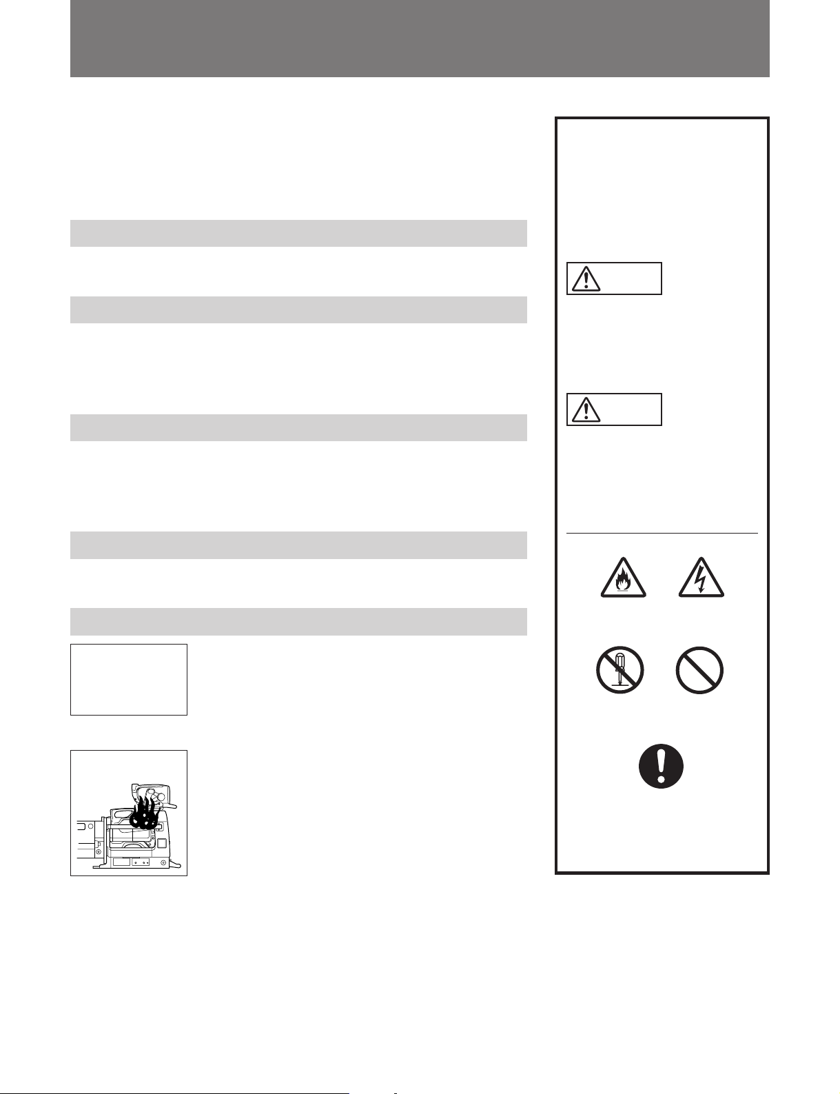
万一、異常が起きたら
1 電源を切る。
異常な音、
におい、煙
が出たら
炎が出たら
/
2 電源コードや接続コードを抜く。
3 ソニーのサービス担当者または営業担当者に修
理を依頼する。
すぐに電源を切り、消火する。
/
注意を促す記号
火災
行為を禁止する記号
分解禁止
行為を指示する記号
強制
感電
禁止
Page 3
目次
警告 .....................................................................................................................
注意 .....................................................................................................................
概要 ...........................................................................................................................
特長...................................................................................................................... 4 (J)
スタジオカメラシステムの構成............................................................................ 5 (J)
各部の名称と働き ....................................................................................................
レンズ接合部 (前面)と端子部1 ........................................................................ 6 (J)
カメラ取り付け部 (内部底面) と端子部2 .......................................................... 7 (J)
ビュー ファ インダー取り付け部 (上面) と表示操作部 (後面)............................ 8 (J)
カメラの組み込みと機材・付属品の取り付け ......................................................
三脚への取り付け ............................................................................................... 9 (J)
スタジオレンズの取り付け................................................................................. 10 (J)
カメラの組み込み .............................................................................................. 12 (J)
カメラとスタジオレンズの接合 .......................................................................... 15 (J)
ポータブルレンズの取り付け ............................................................................ 17 (J)
ビュー ファ インダーの取り付け........................................................................... 19 (J)
ナンバープレー トの取り付け.............................................................................. 19 (J)
接続と操作 ..............................................................................................................
スタジオカメラシステムの接続.......................................................................... 20 (J)
システムの起動とマーカー/ボックスカーソルの操作 ..................................... 21 (J)
仕様 .........................................................................................................................
2 (J)
3 (J)
4 (J)
6 (J)
9 (J)
20 (J)
22 (J)
日
本
語
1 (J)
Page 4
警告
分解禁止
禁止
下記の注意を守らないと、
感電火災
火災や感電 により死亡や大けがにつながることがあります。
分解しない、改造しない
分解したり、改造したりすると、感電の原因となります。
内部に水や異物を入れない
水や異物が入ると火災や感電の原因となります。
万一、水や異物が入ったときは、すぐに電源を切り、トライアックスケーブ
ルや接続コードを抜いて、ソニーのサービス担当者または営業担当者にご相
談ください。
油煙、湯気、湿気、ほこりの多い場所では設置・使用しない
上記のような場所で設置・使用すると、火災や感電の原因となります。
禁止
強制
指定された
指定以外の CCU を使用すると、火災や感電の原因となります。
CCU (
カメラコントロールユニット)を使用する
2 (J)
Page 5
注意
下記の注意を守らないと、
けがをしたり周辺の物品に損害を与えることがあります。
カメラの重量にあった三脚を使用する
カメラの重量に耐えきれない三脚または三脚以外に取り付けて使用すると、
強制
強制
強制
本機やレンズが落下し、けがをすることがあります。
三脚・雲台は確実に固定する
三脚・雲台を確実に固定せずにカメラから離れると、不意にカメラが動いて
けがをすることがあります。
安定した場所に設置する
ぐらついた台の上や傾いたところなどに三脚・雲台を設置すると、カメラが
落下してけがをすることがあります。
機器の取り付けは正しく行う
強制
本機に以下の機器を取り付ける時は、このオペレーションマニュアルの該当
するページをよく読んだうえ、確実に取り付けてください。取り付け方法を
誤るとカメラ等が落下し、けがをすることがあります。
• レンズ
• ビューファインダー
• V ウェッジシュー
3 (J)
Page 6

概要
カメ ラビルドアップユニットCA-901T(以下「本機」と言います)は、
ポータブルタイプのカラービデオカメラBVP-550(以下「カメラ」と
言います)に、スタジオレンズを取り付けるための専用ユニットで
す。
カメラアダプターCA-550を取り付けたカメラを本機に組み込み、カ
メラコントロールユニットCCU-700(以下「CCU」と言います)を接
続し て、スタジオカメラ システムを構成します。
特長
ソニー仕様のスタジオレンズに対応
ソニーハンガーマウントタイプ仕様のスタジオレンズ(DC電源使
用)を取り付け ら れます。 フルサーボタ イプ、手動調整タイプのい
ずれにも対応できます。また、付属のカメラ固定金具をカメラマウ
ントに取り付 けると、 ポー タ ブル レンズ(エクステンダー付き)も使用
でき ます。
屋外での
• 防滴性(レインカバー使用時)
• キャ リングハンドルで持ち運び可能
ENG/EFP
に適した構造
インチビューファインダーが使用可能
7
7インチの白黒ビューファ イ ンダーBVF-77を使用できます。接続
ケーブルは本機に付属しています。
スタジオカメラとしての機能
本機にカメラを組み込み 、スタジオレンズとビューファイ ンダーを取
り付けると、ENG/EFP用カメラの機能に加えて、以下のようなスタ
ジオカメラとしての機能が働きます。
• 後面パネルで、ボックスカーソル、マーカー表示のON/OFF、タ
リーランプの使用/未使用選択などの操作が可能
• AC出力端子(100VA)
• スクリプトライト用端子(5W)と操作スイッチ
システムの組み立て、分解が容易
ビューフ ァインダーの着脱が容易であると同時に、レンズおよび
ビューフ ァイ ンダーを取り付けた状態でカメラを着脱できる構造で
す。
4 (J)
Page 7
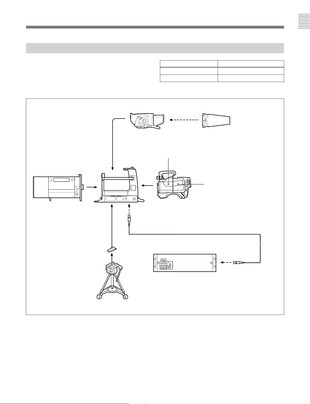
スタジオカメラシステムの構成
本機を含むスタ ジオカメラシステムの構成例を下図に示します。
本機とCCUを接続するトライ アッ クスケーブル((株)フジクラ製 )
の延長可能な長さは、下表に示すとおりです。
インチ白黒ビューファインダー
7
BVF-77
カメラビルド
アップユニット
CA-901T
スタジオレンズ
(本機)
直径 延長可能な長さ
14.5mm 3000m(1800m)
8.5mm 1500(900m)
a)( )内はリターンビデオ機 能を使う場合
屋外撮影用
ビューファインダー
モニターフード
VFH-770
カラービデオカメラ
BVP-550
カメラアダプター
CA-550
a)
(別売り)
ウエッジシュー
V
(三脚に付属)
三脚
トライアックスケーブル
50T/100T/150T/200T
カメラコントロールユニット
CCU-700
スタジオカメラシステムの構成例
CCT-5T/10T/20T/
(別売り)
5 (J)
Page 8
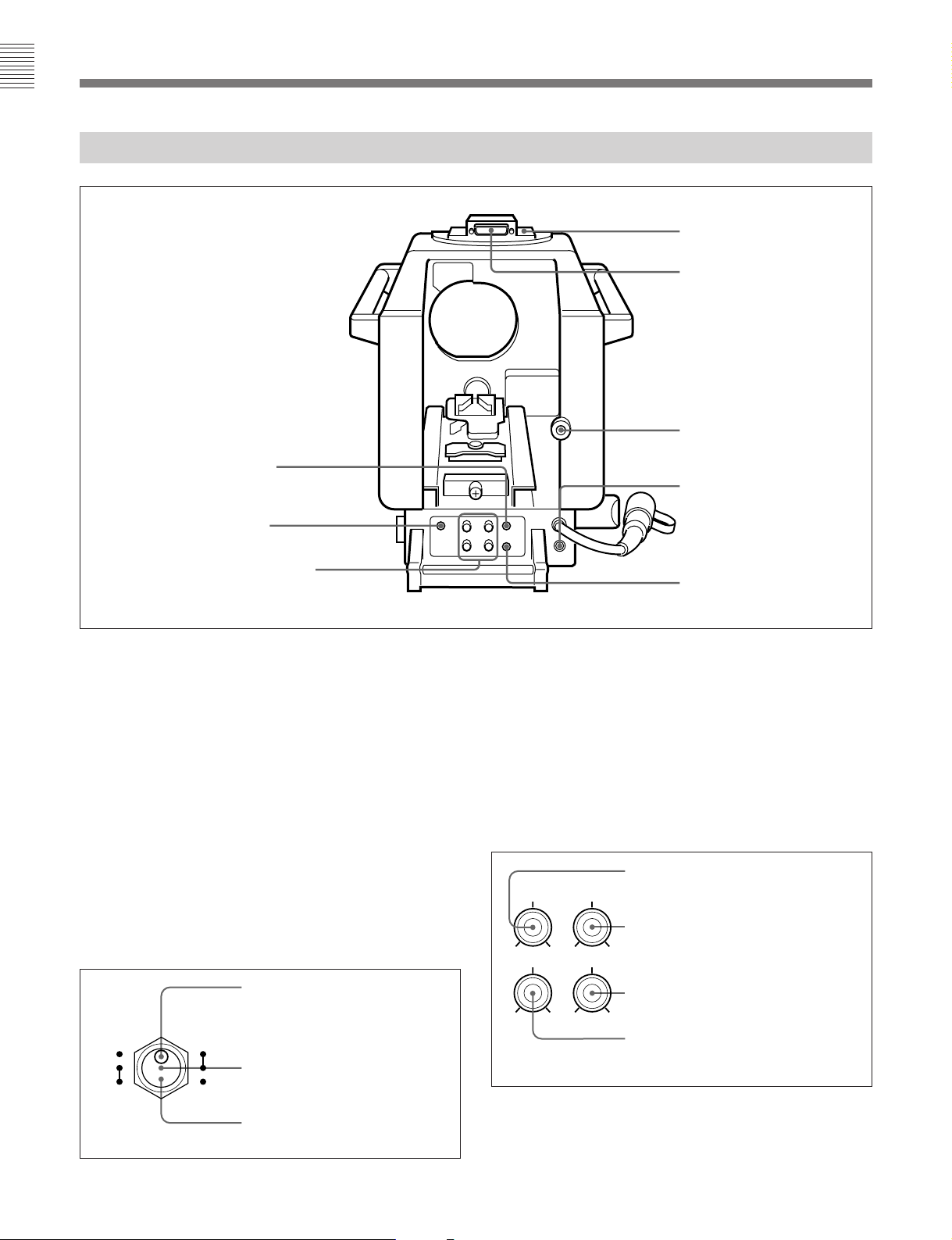
各部の名称と働き
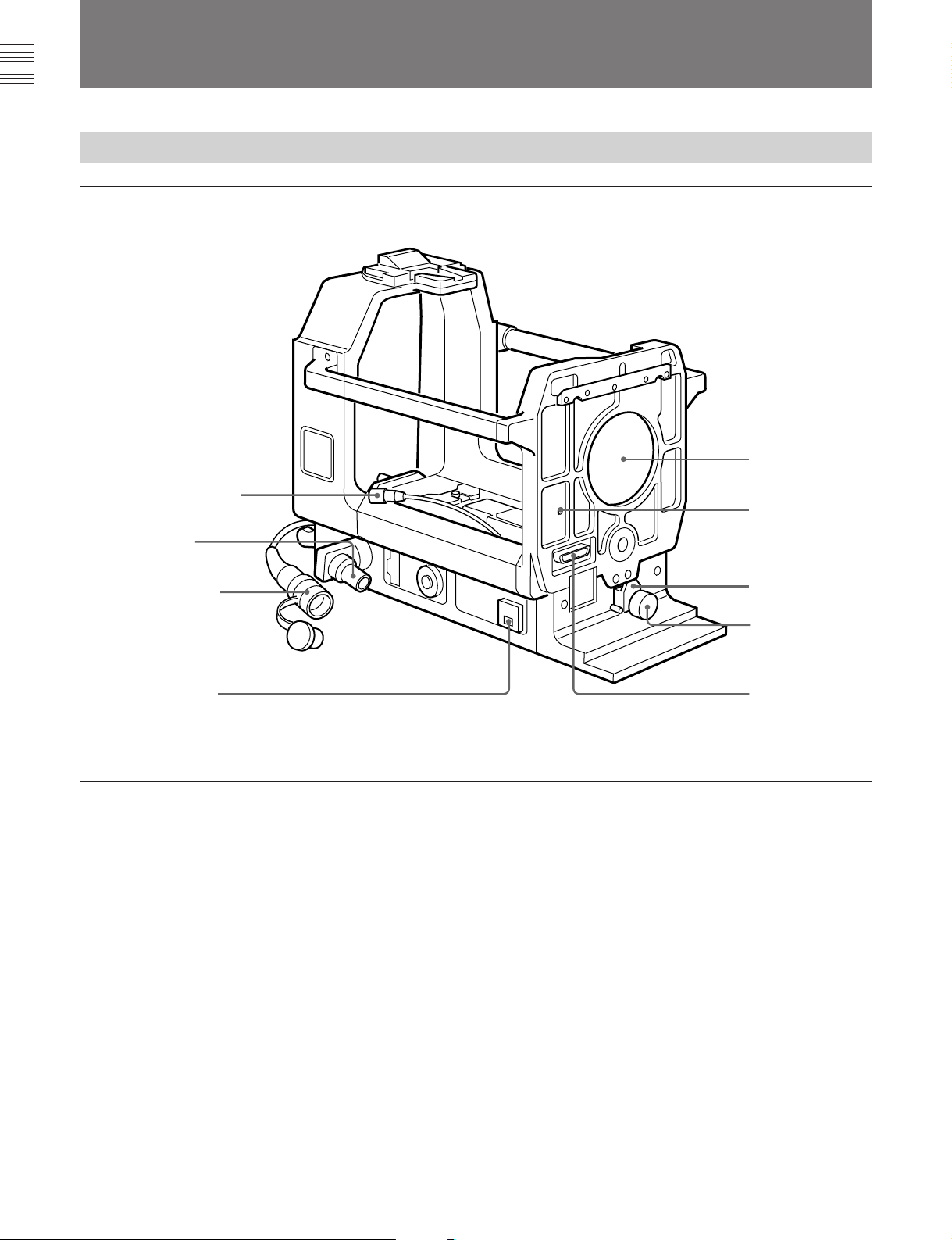
レンズ接合部(前面)と端子部
2
4 レンズコネクター
5
6
CCU
コネクター
CA
端子
1
レンズ口
押し引き棒出口
1 レンズ押さえ
7
AC OUT
レンズ押さえ
1
レンズ の下端を押さえてレンズを固定します。
レンズ押さえ固定つまみ
2
レンズ 押さえ1を固定します。締めるときは右に 、ゆるめるときは 左
に回します。
レンズ端子(36ピン)
3
レンズ のカメラ端子に接続します。
レンズコネクター(12ピン)
4
カメラのLENS端子に接続します。
端子
レンズ接合部と端子部
2 レンズ押さえ
固定つまみ
3 レンズ端子
1
5 CCU
イアックスコネクター)
トライアックスケーブルCCT-5T/10T/20T/50T/100T/150T/200T
(別売り)で、CCUのCAMERA端子に接続します。
6
クスコネクター)
カメラアダ プターCA-550のトライ アッ クス コネク タ ーに接続します。
7
AC電源(100VA)を供給します。
◆ ACOUT端子使用時のトライアックス ケーブルの長さについては、「入力
(カメラコントロールユニット)端子(多治見型トラ
(カメラアダプター)コネクター(多治見型トライアッ
CA
AC OUT(AC
端子/コネクター」(22 (J) ページ) をご覧ください。
電源出力)端子(3ピン)
6 (J)
Page 9
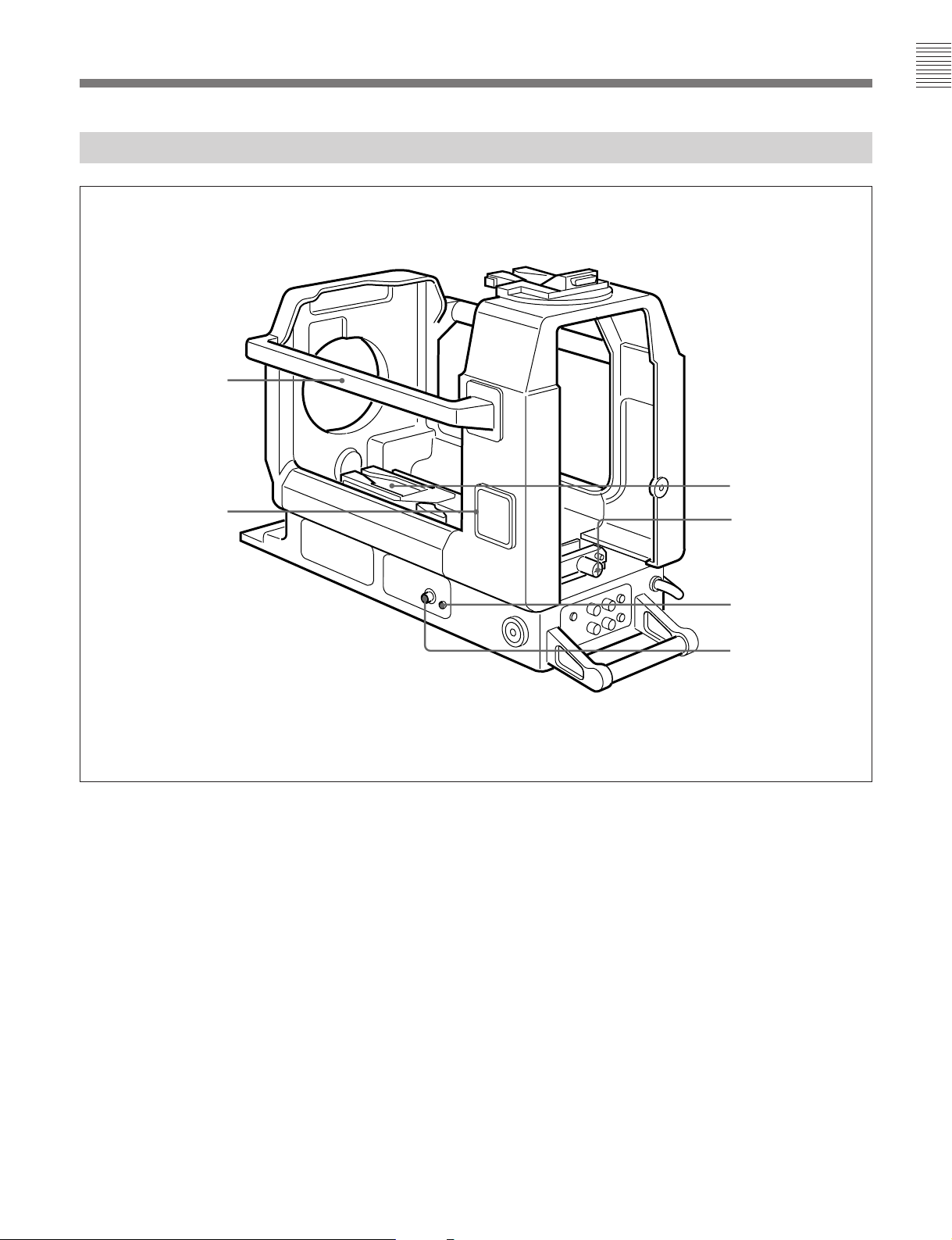
カメラ取り付け部(内部底面)と端子部
キャリングハンドル
5 ナンバープレート
ホルダー
2
1 カメラマウント
2
2 スライド固定つまみ
カメラ取り付け部と端子部
カメラマウント(三脚アタッチメント
1
カメ ラを取り付けます。前後にスライド します。
スライド固定つまみ
2
カメ ラマウントがスライ ドし な い ように 固定します 。 カメラマウ ントを本
機後面側に固定するときは左に、本機前面側に固定するときは右
に回します。
SCRIPT
3
SCRIPT端子4 に接続し た スクリプトライトを入 /切します。
(スクリプトライト)スイッチ
VCT-14
)
3
SCRIPT
4
SCRIPT
2
SCRIPT
4
スクリプトライト用電源(最大5W)を供給します。
ナンバープレートホルダー
5
付属のナンバープレートを取り付 け ます。
(スクリプトライト用)端子(4ピン)
スイッチ
端子
7 (J)
Page 10
各部の名称と働き
ビューファインダー取り付け部(上面)と表示操作部(後面)
1 ビューファインダーマウント
2
VF端子1
押し引き棒挿入口
5
UP TALLY
POWER
6 ボックスカーソル調整つまみ
ビューファインダーマウント
1
スイッチ
ランプ(緑色)
ビューファインダー取り付け部と表示操作部
ビュー ファ インダーを取り付けます。
(ビューファインダー)端子1(25ピン)
VF
2
ビュー ファ インダーのカメ ラ端子と接続します。
(ビューファインダー)端子2(12ピン)
VF
3
付属のビューファインダー用接続ケーブルで、カメラの
VF端子と接続します。
CURSOR/MARKER
4
スイッチ
ビューフ ァインダー画面のボッ ク ス カ ー ソルおよびマーカーの表示を
ON/OFFします。
3
VF端子2
4
CURSOR/MARKER
スイッチ
5 UP TALLY
(アップタリー)スイッチ
ONにすると、タリー信号が入力されたとき、ビュー ファ インダーの外
部タ リーランプが点灯します(ビューフ ァ イ ンダー 画面内のタリーラン
プは操作できません)。
ボックスカーソル調整つまみ
6
ビュ ー ファ インダー画面に表示されるボックスカーソルの、表示位置
や大きさを調整します。各つまみの働きは下図に示すとおりです。
つまみ:水平方向の表示位置を
つまみ:垂直方向の表示位置を
H-POSI V-POSI
WIDTH HEIGHT
H-POSI
調整する。
V-POSI
調整する。
CURSOR MARKER
ON
OFF
8 (J)
CURSOR, MARKER ON
ボックスカーソル、セーフティゾー
ンマーカー、およびセンターマー
カーが表示される。
ON
CURSOR OFF, MARKER ON
セーフティゾーンマーカーとセン
OFF
ターマーカーが表示される。
CURSOR OFF, MARKER OFF
表示は出ない。
CURSOR/MARKER
スイッチ
:
HEIGHT
内で、ボックスカーソルの高さを調整す
る。
WIDTH
で、ボックスカーソルの幅を調整する。
:
ボックスカーソル調整つまみ
:
つまみ:セーフティゾーン範囲
つまみ:セーフティゾーン範囲内
Page 11

カメラの組み込みと機材・付属品の取り付け
三脚への取り付け
1 本機を水平で安定な台の上に、底面が見
えるよう に 横倒しに起きます。
2 Vウエッジシュー(三脚に付属)をネ ジ(三
脚に付属)で本機の底面に取り付けます。
Vウェッ ジシューの取り付け位置には、本
機、カメ ラ、 ビュ ー ファ インダー、 スタジオレ
ンズの総重量 と三脚の雲台の大きさを考 慮
して、本機が三脚上で安定する位置を選
んでください。
3 本機を三脚の雲台に取り付けます。
本機前面
ネジ(三脚に付属)
本機底面
ウェッジシュー(三脚に付属)
V
9 (J)
Page 12
カメラの組み込みと機材・付属品の取り付け
スタジオレンズの取り付け
1 レンズ押さえ固定つまみをゆるめ、レンズ押
さえを 左に 倒 す。
2 レンズ後面のピ ンを本機前面の U字溝に差
し込み、レンズのエッジを本機の突起部に
引っかけ る。
ピン エッジ
本機前面
レンズ押さえ
レンズ押さえ固定
つまみ
字溝 突起部
U
10 (J)
Page 13
3 レンズ後面を本機前面に押しつけ、レンズ
押 さえを右に起 こしてレンズ下端を押さえ
る。 レンズ押さえ固定つまみを締める。
レンズキャッ プを取り外す。
レンズ押さえ固定
つまみ
レンズ押さえ
11 (J)
Page 14
カメラの組み込みと機材・付属品の取り付け
カメラの組み込み
カメラの準備
1 1.5インチビュー ファ インダーを取り外す。
2 カメラのVF端子に、付属のビューファイン
ダー接続ケーブルを接続する。
レンズ固 定レバーを上 方に回し、レンズ マウ
ントキャップを取り外 す。
VF
インチビューファインダー
1.5
端子
端子
VF
12 (J)
ビューファインダー
接続ケーブル
レンズ固定レバー
レンズマウントキャップ
Page 15

組み込みかた
1 カメラマウントを本機後面側に寄せ、スライ
ド固定つまみを締める(左に回す)。
ご注意
カメ ラマウントが バンドで固定さ れ て いるとき
(本機を輸送した直後など)は、先に固定
バンドを外してく ださい。
また、本機を 輸 送するときは、カメラマウン
トを本機前面側 に寄せ てスライド固定つまみ
を締め (右に回す)、必 ずこの バン ドでカ メ
ラマウントを固定して ください。
2 カメラを持ち上げ、本機後面からカメラを本
機内に入れる。このとき、ビューファイン
ダー接続ケーブルを本機後面から外に出し
てお く。
カメ ラに 胸当てパッ ドを取り付けている場 合
は、本機の側板を開けると以降の操作が容
易になり ま す。
カメラマウント
スライド固定
つまみ
ビューファインダー接続
ケーブル
3 カメラ底面のVウェッジシューをカメラマウン
ト(三脚アタッチメントVCT-14)のV字溝に
はめ、ロ ックされ る位置ま でカ メラ を前方に
スライ ドする 。
「カチ ッ 」と音がしてロックがかかったことを
確認してください。
カメラ
カメラマウント
(続く)
13 (J)
Page 16

カメラの組み込みと機材・付属品の取り付け
4 レンズコネクターをカメ ラのLENS端子に接
続する。
5 ビューフ ァインダー接続ケーブ ルのコネク
ターを、本機後面のVF端子2に接続する。
本機のCAコネクターをCA-550のトライアッ
クスコネクターに接続 する。
レンズコネクター
端子
LENS
本機後面
CA-550
トライアックスコネクター
ビューファインダー
接続ケーブル
コネクター
CA
VF端子2
14 (J)
Page 17

カメラとスタジオレンズの接合
1 スライ ド固定つまみをゆるめる(右に回す)。
2 カメラを本機前面側に移動し、カメラの後
部を持ち上げて、カ メラの レンズマウントと
レンズのマウント接合部を合わせる。
3 カメラを持ち上げたま ま、レンズ固定レバー
を下方に回して締め る。
レンズマウント
マウント接合部
レンズ固定レバー
(続く)
15 (J)
Page 18

カメラの組み込みと機材・付属品の取り付け
4 スライド固定つまみをコインなどで締める
(右に回す)。
スライド固定つまみ
スタジオレンズを取り外すときは
1 スライ ド固定つまみをゆるめる(左に回す)。
2 カメラ の後部を持ち 上げ 、レンズ固定レバーを上方に回す。
3 カメラを持ち上げて後方に引き、カメラのレンズマウ ン トとレン
ズのマウント接合部を引き離す。
4 カ メラを本機後面側 に引き下げ、スライ ドロ ッ クつまみを締める
(左に回す)。
5 接続ケ−ブルをすべて取り外し、カメラを取り出す(カメラマ
ウン トの赤いボタ ンを押しながら、 レバー を手前に引 くとロック
が外れます)。
6 レ ンズを取り 外す。
ご注意
手動調整のスタジオレンズを使用しているときは、必ず押し引
き棒を取り外してからスタジオレンズを取り外してく ださい。
16 (J)
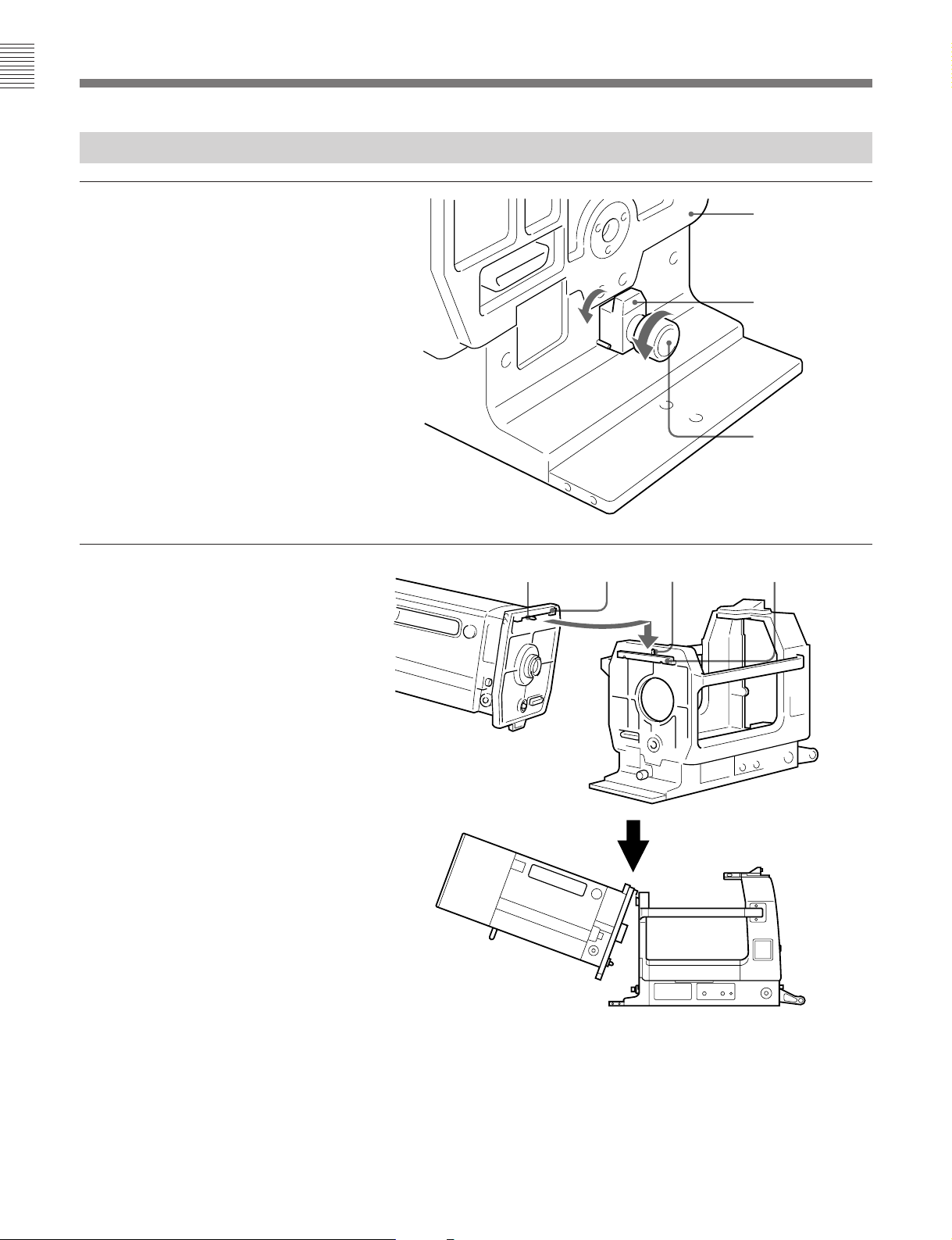
Page 19

ポータブルレンズの取り付け
1 プラスネジ(× 4) をゆるめ、カメラマ ウント
台を取り外す。
2 カメラマウ ントの下 に 付属のカ メラ 固定金具
をはさ む。
カメラマウント(三脚ア
タッチメント
カメラマウント台
VCT-14
)
プラスネジ
3 カメラマウ ント台裏面の穴に、
(×2、付属品)を差し込み、付属のLレン
チで締める。
3
/16インチネジ
カメラマウント
カメラマウント台
カメラマウント台裏面
カメラ固定金具
(付属品)
3
インチネジ(付属品)
/16
レンチ(付属品)
L
(続く)
17 (J)
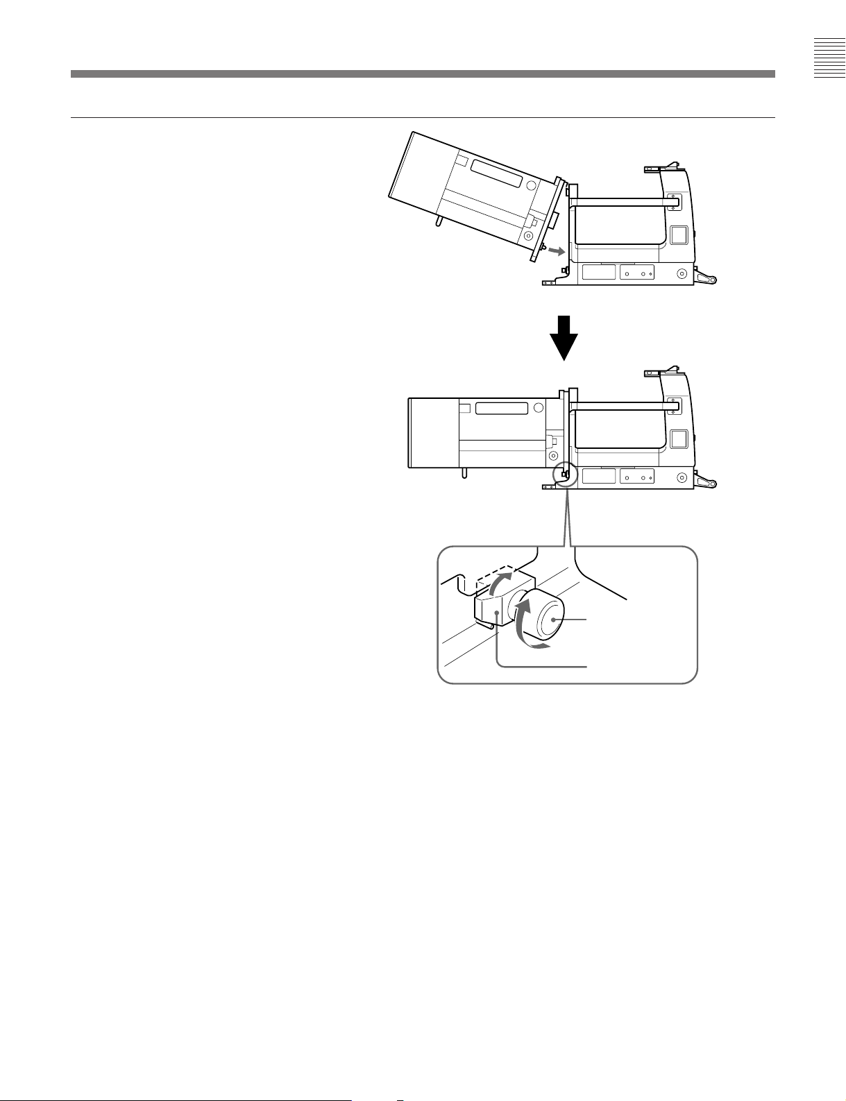
Page 20

カメラの組み込みと機材・付属品の取り付け
4 カメラマウント台を 本 機に取り付 ける。
5 スライ ド固定つまみをゆるめて (右に回す)
カメ ラマウン トを本機前面側に移動し、スラ
イド固定つまみをコインなどで締める(右に
回す)。
6「カメラの組み込み」(12(J)ページ)を参照
して、本機にカメラ を組み込む。
カメラマウント台
カメラ固定金具
カメラ固定金具とカメラ
マウント台を一緒にネジ
止めします。
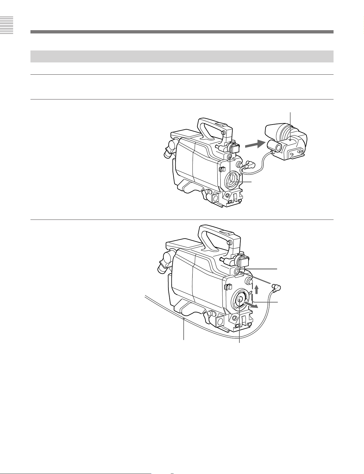
7 本機前面のレンズ口から、ポータブルレン
ズのマウント接合部を 本機内に入れ、カメラ
のレンズマウントに取り付ける。 レンズ固定
レバー を下方に回して締める 。
8 ポータブルレンズのレンズコネクターをレン
ズ口から本機内に入れ、カメラのLENS端
子に接続する。
レンズ口
ポータブルレンズ
マウント接合部
レンズ固定レバー
レンズマウント
18 (J)
Page 21

ビューファインダーの取り付け
取り付けかた
ビュー ファ インダーが標準位置にロックされていることを確認してか
ら(次項参照)、ビューファインダーを取り付けてく ださい。
ビューファインダー
マウント
ウエッジシュー
V
ビューファインダーの取り付け
ビューファインダーマウ ントのV字溝に、ビューファ イ ンダー底面のV
ウエ ッ ジシュ ー をはめ、ロックされる位 置 までビ ューファインダーをス
ライドさせます。ロックされると「カチッ」 と音がします。
1 ロックレバ ーを手 前に 倒し、ロックを 解 除 する。
2 フリクション調整ノブを左に回してゆる め る 。リフトロック解除つ
まみを引き下ろ しながら 、 ビューファインダーの取っ手を持っ
て、ビューファ イ ンダーを最下段(標準位置)まで押し下げる。
3 フリクショ ン調整ノブを右に回して締め、ロッ クレバーをレンズ
側に 倒してロックする。
取り外しかた
ビューファイ ンダーが標準位置にロックされていることを確認して か
ら(前ページ参照)、ビューフ ァイ ンダーを取り外してく ださい。
レバーを引きながらボタンを押
し、同時にビューファインダー
を後ろに引いて外します。
ボタン
レバー
◆本機には5インチビューファインダーBVF-55を取り付けることもできます。
取り付けかた について は、メンテナンスマニュ ア ルを ご覧ください。
標準位置に戻すには
高さや角度を調節してビューフ ァイ ンダーを使用したときは、以下の
手順で標準位置に戻し、ロックします。
ご注意
ビュー ファ インダーの取り付け、取り外しを行う ときは、 ビューファ イ
ンダーを必ず標準位置にロックしてください。
フリクション調整ノブ
1
ロックレバー
リフトロック解除
つまみ
2
ビューファインダーの取り外し
ナンバープレートの取り付け
下図のように、付属のナンバープレートをナンバー プレ ートホル ダ ー
に取り付けます。
ナンバ−プレ−ト左右両端の突起を
ホルダ−の溝に差し込みます。
2
標準位置への戻しかた
ナンバ−プレ−トホルダ− ナンバ−プレ−ト
ナンバープレートの取り付け
19 (J)
Page 22

接続と操作
本機にカメラを組み込んで使用するときは、通常CCUを介して、
カメラへの電源の供給やセットアップおよび撮影操作を行い ます。
スタジオカメラシステムの接続
カメラを本機に組み込んで、スタ ジオカメ ラシステムを構成する場
合の接続を下図に示します。
インチ白黒ビュー
7
ファインダー
キャノンケーブル
マイク
BVF-77
ヘッドセット
カメラビルドアップユニット
CA-901T
(本機)
MIC
OUTPUT
INTERCOM/
TALLY/PGM
インターカム
プログラム音声
マイク音声出力
端子
端子
/
端子へ
CCU
プロンプター入力信号
PROMPTER
端子
INPUT
カメラコントロール
ユニット
CCU-700
RET 1〜RET 4
端子
INPUT
AC
リターンビデオ信号
カラービデオカメラ
INCOM/PGM
MIC IN
CAMERA
⁄ AC IN
電源
端子
BVP-550
ジャックへ
端子へ
カメラアダプター
端子へ
CA-550
トライアックス
ケーブル
20 (J)
スタジオカメラシステムの接続
Page 23

システムの起動とマーカー/ボックスカー
ソルの操作
ここでは、カメ ラを単独で操作する場合と異なる点につ いてのみ説
明します。
システムの起動(必ず下記の手順に従ってくださ
い。)
1 CA-550のPOWERスイッチをCCU/EXTに設定する。
ボックスカーソルの操作
1 本機後面のCURSOR/MARKERスイッチをCURSORONに
する。
ビューフ ァイ ンダー画面にボックスカーソル、セーフティゾーン
マーカ ー 、およびセ ン ターマーカ ーが表示 さ れます。
セーフティゾーン
マーカー
2 CCUのMAINPOWERスイッチとCAMERAPOWERスイッ
チをONにする 。
本機後面の電源ランプが点灯(緑色)します。
マーカー表示
本機後面のCURSOR/MARKERスイッチをMARKERONにしま
す。
MARKER ON、CURSOR ON
ダー画面にボックスカーソル、セーフ テ ィゾーン(撮影画面の
90%の範囲を示す)マーカー、およびセ ンターマー カ ーが表示
されます。
MARKER ON、CURSOR OFF
ダー画面にセ ーフティゾーンマーカーとセンターマーカーが表
示されます。
セーフテ ィゾーンの大きさを撮影画面の80%に変更するときは、本
機の内部スイッチを切り換えます。
にすると:ビューファ イン
にすると:ビューフ ァイ ン
ボックス
カーソル
センターマーカー
ビューファインダー
画面
2 H-POSI、V-POSI、WIDTH、HEIGHTつまみを使って、ボック
スカーソルの表示位置と大きさを調整する。
◆ 詳しく はメンテナ ン ス マニュ アル を ご覧ください。
ご注意
カメラ側でマーカー表示をONにした状態で、本機のCURSOR/
MARKERスイッチをMARKERONにすると、マーカーが二重に表
示されます。必ず、カメラ側のマーカー表示をOFFに してください。
21 (J)
Page 24

仕様
一般
質量 16.5kg
外形寸法 260mm×413mm×522mm
(幅/高さ/奥行き)
413
522
動作温度 −20℃〜+45℃
保存温度 −20℃〜+60℃
260
340
(単位:mm)
付属品
オペ レーションアンドメンテナンスマニュアル(1)
7インチ白黒ビューファインダーBVF-77用接続ケーブル(1)
カメラ固定金具(1)
3
/16インチネジ(2)
3
Lレンチ(
ナンバープレー ト(1組)
/16インチネ ジ用、1)
別売りアクセサリー
トライアックスケーブ ル
CCT-5T/10T/20T/50T/100T/150T/200T
7インチ白黒ビューファインダー
BVF-77
屋外撮影用ビューファインダーモニターフード
VFH-770
リターンビデ オセレクター
CAC-6
入出力端子/コネクター
CCU端子(多治見型トライ アックスコネクター)
レンズ端子(36ピン)
レンズコネクタ ー (12ピン)
VF端子1(25ピン)
VF端子2(12ピン)
CA コネクター (多治見型トライアックスコネクター)
1)
ACOUT端子
SCRIPT端子(4ピン)
1) ACOUT端子を使用する場合、CCU端子に接続するトライ アッ クスケー
ブルの長さは、1200m(直径14.5mm)または600m (直径8.5mm)以下
にしてください。
(3ピン)
関連機器
カラービデオカメラ BVP-550
カメラアダプター CA-550
カメ ラコントロールユニット
CCU-700
リモートコントロールパネル
RCP-7xxシリーズ
仕様および外観は、改良のため予告なく変更することがあります
が、ご了承ください。
22 (J)
Page 25

Page 26

WARNING
VORSICHT
To prevent fire or shock hazard, do not
expose the unit to rain or moisture.
To avoid electrical shock, do not open the
cabinet. Refer servicing to qualified
personnel only.
For the customers in the USA (for CA-901K)
This equipment has been tested and found to comply with
the limits for a Class A digital device, pursuant to Part 15 of
the FCC Rules. These limits are designed to provide
reasonable protection against harmful interference when the
equipment is operated in a commercial environment. This
equipment generates, uses, and can radiate radio frequency
energy and, if not installed and used in accordance with the
instruction manual, may cause harmful interference to radio
communications. Operation of this equipment in a residential
area is likely to cause harmful interference in which case the
user will be required to correct the interference at his own
expense.
You are cautioned that any changes or modifications not
expressly approved in this manual could void your authority
to operate this equipment.
The shielded interface cable recommended in this manual
must be used with this equipment in order to comply with the
limits for a digital device pursuant to Subpart B of Part 15 of
FCC Rules.
Um Feuergefahr und die Gefahr eines elektrischen Schlages
zu vermeiden, darf das Gerät weder Regen noch
Feuchtigkeit ausgesetzt werden.
Um einen elektrischen Schlag zu vermeiden, darf das
Gehäuse nicht geöffnet werden. Überlassen Sie
Wartungsarbeiten stets nur einem Fachmann.
For the customers in Europe (for CA-901F)
WARNING
This is a Class A product. In a domestic environment, this
product may cause radio interference in which case the user
may be required to take adequate measures.
Pour les utilisateurs en Europe (pour CA-901F)
AVERTISSEMENT
Il s’agit d’un produit de Classe A. Dans un environnement
domestique, cet appareil peut provoquer des interférences
radio, dans ce cas l’utilisateur peut être amené à prendre
des mesures appropriées.
Für Kunden in Europa (für CA-901F)
Warnung
Dies ist eine Einrichtung, welche die Funk-Entstörung nach
Klasse A besitzt. Diese Einrichtung kann im Wohnbereich
Funkstörungen verursachen; in diesem Fall kann vom
Betreiber verlangt werden, angemessene Maßnahmen
durchzuführen und dafür aufzukommen.
Für Kunden in Deutschland
Dieses Gerät ist nur für den Gebrauch in Gewerbe und
Leichtindustrie bestimmt. Es entspricht der Klasse A, es
erfüllt nicht die Grenzwerte der Klasse B. In Deutschland
muß der Erwerber eine spezielle Betriebserlaubnis bei der
zuständigen Außenstelle des BAPT beantragen, um dieses
Gerät betreiben zu dürfen.
Page 27

Contents
English
Overview............................................................................................... 2(E)
Features ...........................................................................................2(E)
System Configuration......................................................................3(E)
Location and Function of Parts.......................................................... 4(E)
Lens Attachment Section (Front) and Connectors 1 .......................4(E)
Camera Mount Section (Inner Base) and Connectors 2 ..................5(E)
Viewfinder Mount Section (Top) and Display Controls (Rear)......6(E)
Fitting the Camera, Equipment and Accessories ............................. 7(E)
Fitting to the Tripod ........................................................................7(E)
Attaching the Studio Lens ...............................................................8(E)
Fitting the Camera .........................................................................10(E)
Connecting the Camera and Studio Lens ......................................13(E)
Attaching a Portable Lens .............................................................15(E)
Attaching the Viewfinder ..............................................................17(E)
Fitting the Number Plates..............................................................17(E)
Connections and Operation .............................................................. 18(E)
Connecting a Studio Camera System ............................................18(E)
System Start-up and Viewfinder Display Control.........................19(E)
Specifications...................................................................................... 20(E)
1(E)
Page 28

Overview
The CA-901K/901F Camera Build-Up Unit (called
“the unit” in this manual) allows you to connect a
studio lens and the BVP-550 portable color video
camera (called “the camera” in this manual)
incorporated into this unit.
You can configure a studio camera system by
attaching the CA-550/550P Camera Adaptor to the
camera and connecting a CCU-700/700P Camera
Control Unit (called “the CCU” in this manual) to this
unit.
Features
Compatible with Sony specification lenses
The unit allows you to attach Sony hanger-type lenses
(DC powered). It is compatible with both full servocontrol and manual control lenses. You can also use a
portable lens (with extender) if you attach the supplied
camera stabilizer to the camera mount.
Easy to assemble and disassemble
It is easy to attach and detach the viewfinder, and to fit
and remove the camera without detaching the lens and
viewfinder.
Suitable for outdoor ENG/EFP
•Rain cover for protection against moisture.
•Carrying handle for portability.
Seven-inch viewfinder
You can use either the BVF-77/77CE seven-inch
monochrome viewfinder. Use the cables supplied with
this unit to connect the viewfinder.
Functions for studio camera
When you fit the camera with a studio lens and
viewfinder to this unit you will be able to use the
following functions suitable for studio shootings in
addition to those for ENG and EFP:
•You can perform a variety of operations from the rear
panel, such as selecting whether or not you use the
tally indicator and controlling the box cursor and
marker displays in the viewfinder.
•AC output connector (CA-901K: 120 V AC, CA-
901F: 220 or 240 V AC).
•Script light connector (5 W) and on/off switch.
2(E)
Page 29

System Configuration
An example configuration of a studio camera system
using this unit is shown below.
Triaxial cables are available to connect this unit and a
CCU.
BVF-77/77CE 7-inch
monochrome viewfinder
CA-901K/901F
Camera Build-Up
Unit (this unit)
Studio lens
Maximum cable lengths are as follows:
Triaxial cable Maximum length
Fujikura (dia.14.5 mm) 3000 m (1800 m)
Belden 9232 2250 m (1800 m)
Fujikura (dia.8.5 mm) 1500 m (900 m)
a) Figures in parentheses for use with video return function.
VFH-770 outdoor
viewfinder hood
(available separately)
BVP-550 Color Video
Camera
a)
V-wedge shoe
(supplied with tripod)
CA-550/550P
Camera Adaptor
CCT-K5T/K10T/K20T/K50T/K100T/K150T/K200T or CCT-5/
10/20/50/100/150/200 triaxial cable (available separately)
CCU-700/700P
Camera Control Unit
Tripod
Studio camera system configuration
3(E)
Page 30

Location and Function of Parts
Lens Attachment Section (Front) and Connectors 1
2
4 Lens connector 2
5 CCU connector
6 CA connector
7 AC OUT connector
Lens attachment section and connectors 1
1 Lens hold lever
Holds the lens by the tongue-like protrusion at the lens
bottom.
2 Lens hold lever locking knob
Locks the lens hold lever 1. Turn clockwise to
tighten, and counterclockwise to loosen.
3 Lens connector 1 (36-pin)
Connect to the camera connector of the lens.
Lens mouth
Pushrod exit
1 Lens hold lever
2 Lens hold lever
locking knob
3 Lens connector 1
6 CA (camera adaptor) connector (triaxial
connector, Kings type for the CA-901K, and
Fischer type for the CA-901F)
Connect to the CCU-550/550P connector of the CA550/550P camera adaptor.
7 AC OUT (AC power output) connector (3-pin)
AC power supply (CA-901K: 120 V AC, CA-901F:
220 or 240 V AC) for external equipment is available
via this connector.
4 Lens connector 2 (12-pin)
Connect to the LENS connector of the camera.
5 CCU (camera control unit) connector (triaxial
connector, Kings type for the CA-901K, and
Fischer type for the CA-901F)
Connect to the CAMERA connector of the CCU with
CCT-K5T/K10T/K20T/K50T/K100T/K150T/K200T
(for CA-901K) or CCT-5/10/20/50/100/150/200 (for
CA-901F) triaxial cable (available separately).
4(E)
When using the AC OUT connector, see the section “Input/
output connectors” on page 20(E) for the maximum triaxial
cable lengths for connection to the CCU connector.
Page 31

Camera Mount Section (Inner Base) and Connectors 2
Carrying handle
5 Number plate
holder
2
1 Camera mount
2 Slide lock knob
3 SCRIPT switch
Camera mount section and connectors 2
1 Camera mount (VCT-14 tripod attachment)
Fit the camera. Slides to the front and rear.
2 Slide lock knob
Locks the camera mount 1 so it does not slide.
Turn counterclockwise to lock the camera mount at the
far rear, and clockwise to lock it at the very front.
3 SCRIPT (script light) switch
Turns the script light connected to the SCRIPT
connector 4 on and off.
4 SCRIPT connector
4 SCRIPT connector (4-pin)
Supplies power (maximum 5 W) for a script light.
5 Number plate holder
Fit the supplied number plates.
5(E)
Page 32

Location and Function of Parts
Viewfinder Mount Section (Top) and Display Controls (Rear)
5 UP TALLY switch
1 Viewfinder mount
2 VF connector 1
Pushrod hole
3 VF connector 2
Power indicator
6 Box cursor control knob
Viewfinder mount section and display controls
1 Viewfinder mount
Attach the viewfinder.
2 VF connector 1 (25-pin)
Connect to the camera connector of the viewfinder.
3 VF connector 2 (12-pin)
Connect to the VF connector of the camera, using the
supplied viewfinder cables.
4 CURSOR/MARKER switch
Turns the box cursor and markers in the viewfinder on
and off.
CURSOR ON, MARKER ON:
Displays the box cursor, the safety
CURSOR MARKER
ON
OFF
zone marker, and the center marker.
ON
CURSOR OFF, MARKER ON:
Displays the safety zone marker
OFF
and the center marker.
CURSOR OFF, MARKER OFF:
No displey.
4 CURSOR/MARKER switch
5 UP TALLY switch
Turn to ON if you want the viewfinder’s exterior tally
indicator to light when a tally signal is input (the tally
indicator displayed on the viewfinder monitor screen
cannot be controlled).
6 Box cursor control knobs
Control the size and position of the box cursor
displayed in the viewfinder. The function of the each
knob is as follows.
H-POSI knob: Moves the cursor
H-POSI V-POSI
WIDTH HEIGHT
horizontally.
V-POSI knob: Moves the cursor
vertically.
HEIGHT knob: Changes the width of
the box cursor in the safety zone.
WIDTH knob: Changes the width of the
box cursor in the safety zone.
Box cursor control knobs
6(E)
CURSOR/MARKER switch
Page 33

Fitting the Camera, Equipment and Accessories
Fitting to the Tripod
1 Place the unit on its side on a
stable stand, so that you have a
good view of the base.
2 Attach the V-wedge shoe
supplied with the tripod to the
base of the unit, using the
screws supplied with the
tripod.
When attaching the V-wedge
shoe, taking the total weight of
this unit, the camera, studio
lens and viewfinder, and the
size of the pan and tilt head
into consideration, choose a
position such that the unit will
be mounted stably on the
tripod.
3 Attach the unit to the pan and
tilt head of the tripod.
Base of the unit
Front of the unit
Screws (supplied with tripod)
V-wedge shoe (supplied with tripod)
7(E)
Page 34

Fitting the Camera, Equipment and Accessories
Attaching the Studio Lens
1 Loosen the lens hold lever
locking knob and turn the lens
hold lever counterclockwise.
2 Insert the pin on the rear of the
lens into the U-shaped notch
on the front of the unit, and
catch the lens edge on the
projection of the unit.
Front of the unit
Lens hold lever
Lens hold lever locking knob
Pin Lens edge U-shaped notch Projection
8(E)
Page 35

3 Push the rear face of the lens
onto the front face of the unit.
Turn the lens hold lever
clockwise so that it holds down
the tongue-like protrusion at
the lens bottom, and tighten the
lens hold lever locking knob.
Lens hold lever
locking knob
Lens hold lever
9(E)
Page 36

Fitting the Camera, Equipment and Accessories
Fitting the Camera
Preparing the camera
1 Remove the 1.5-inch
viewfinder.
2 Connect the supplied
viewfinder cable to the
camera’s VF connector.
Turn the lens locking lever
upward and remove the lens
mount cap.
1.5-inch viewfinder
VF connector
VF connector
10(E)
Viewfinder cable
Lens locking lever
Lens mount cap
Page 37

Fitting the camera
1 Slide the camera mount to the
far rear, and tighten the slide
lock knob (turn
counterclockwise).
Note
The camera mount may be
retained with a belt, for
example after the unit is
transported. Undo the belt
before moving the camera
mount.
When you transport the unit,
slide the camera mount to the
very front and tighten this belt
to retain the camera mount.
2 Pick up the camera, and insert
from the rear of the unit. Draw
the viewfinder cables out from
the rear of the unit.
When the chest pad is attached
to the camera, opening the side
panel of this unit allows you to
perform the following
procedures easier.
Camera mount
Slide lock knob
3 Insert the V-wedge shoe on the
base of the camera into the Vshaped groove on the camera
mount (VCT-14 tripod
attachment), and slide the
camera forward until it clicks
in place.
Viewfinder cable
Camera
Camera mount
(Continued)
11(E)
Page 38

Fitting the Camera, Equipment and Accessories
4 Connect the lens connector 2
to the camera’s LENS
connector.
5 Connect the viewfinder cable
to the VF connector 2 on the
rear of this unit.
Connect the CA connector of
this unit to the triaxial
connector of the CA-550/550P.
Lens connector
LENS connector
Rear of this unit
CA-550/550P
Triaxial connector
6 If necessary, attach the camera
grip.
For procedures on attaching the
grip, refer to the camera’s
operation manual.
Viewfinder cable
CA connector
VF connector 2
12(E)
Page 39

Connecting the Camera and Studio Lens
1 Loosen the slide lock knob
(turn clockwise).
2 Slide the camera forward.
Pick up the rear of the camera,
and connect the camera’s lens
mount to the mount joint of the
lens.
3 While holding the camera,
tighten the lens locking lever
by turning downward.
Lens mount
Mount joint
Lens locking lever
(Continued)
13(E)
Page 40

Fitting the Camera, Equipment and Accessories
4 Tighten the slide lock knob
with a coin or screwdriver
(turn clockwise).
Slide lock knob
Removing the studio lens
1 Loosen the slide lock knob (turn
counterclockwise).
2 Pick up the rear of the camera, and turn the lens
locking lever upward.
3 Lift the camera up and pull backward to disengage
the camera’s lens mount from the mount joint.
4 Pull the camera to the far rear, and tighten the slide
lock knob (turn counterclockwise).
5 Disconnect all the cables and then remove the
camera. The lock is released when you pull the
lever on the camera mount holding the red button
on the lever.
6 Remove the lens.
Note
When using a manual control lens, be sure to remove
the push rod before removing the lens.
14(E)
Page 41

Attaching a Portable Lens
1 Loosen the four Phillips screws
and remove the camera mount
base.
2 Insert the supplied camera
stabilizer under the camera
mount.
Camera mount (VCT-14
tripod attachment)
Camera mount base
Phillips screws
Camera mount
3 Insert the two
3
/16 inch screws
(supplied) into the holes on the
rear side of the camera mount
base, and tighten using the
supplied L-wrench.
Camera mount base
Rear side of the camera
mount base
Camera stabilizer
(supplied)
3
/16 inch screws (supplied)
L-wrench (supplied)
(Continued)
15(E)
Page 42

Fitting the Camera, Equipment and Accessories
4 Attach the camera mount base
to this unit.
5 Loosen the slide lock knob
(turn clockwise), slide the
camera to the very front and
tighten with a coin or
screwdriver (turn clockwise).
6 Insert the camera into the unit,
following the procedure in
Section “Fitting the Camera”
(page 10(E)).
Camera mount base
Camera stabilizer
Screw the camera stabilizer and
camera mount base together to
the inner base of this unit.
7 Insert the mount joint of the
portable lens through the lens
mouth on the front of this unit
and connect to the camera’s
lens mount. Supporting the
lens, turn the lens locking lever
downward.
8 Insert the lens cable of the
portable lens through the lens
mouth of this unit, and connect
to the LENS connector of the
camera.
Lens mouth
Portable lens
Mount joint
Lens locking lever
Lens mount
16(E)
Page 43

Attaching the Viewfinder
Attaching the viewfinder
Insert the V-wedge shoe on the base of the viewfinder
in the V-shaped groove on the viewfinder mount, and
slide the viewfinder forward until it locks in place.
Viewfinder mount
1 Pull the tilt lock lever forward to release the lock.
2 Loosen the friction control knob by turning
counterclockwise. While pulling the lift lock
release lever down, grasp the handle and pull the
viewfinder down to the lowest position (standard
position).
3 Tighten the friction control knob by turning
clockwise, and lock by pushing the tilt lock lever
toward the lens.
Removing the viewfinder
V-wedge shoe
Attaching the viewfinder
Before you attach or detach the viewfinder, be sure to
verify that it is locked in standard position (see the
following paragraph).
The BVF-55/55CE 5-inch viewfinder can be also attached to
this unit. For procedures on attaching the BVF-55/55CE,
refer to the maintenance manual.
Locking the viewfinder in standard position
After using the viewfinder at an adjusted height or
angle, proceed as follows to return it to standard
position and lock it.
Note
Always lock the viewfinder in standard position when
you attach or detach it from the unit.
Friction control knob
1
Tilt lock lever
Verify that the viewfinder is locked in standard
position (see the previous section), then remove the
viewfinder.
Push the button while pulling
the lever forward, and slide the
viewfinder backward.
Removing the viewfinder
Button
Lever
Fitting the Number Plates
Fit the supplied number plates to the number plate
holder.
Lift lock release knob
2
Locking the viewfinder in standard position
Number plate holder
Fitting the number plate
Insert the projections on the both
side of the number plate into the
notches on the frame.
2
Number plate
17(E)
Page 44

Connections and Operation
After assembling a system consisting of this unit and a
camera, you will usually supply power to the camera
and conduct setup and shooting operations via a CCU.
Connecting a Studio Camera System
The illustration below shows connections for a studio
camera system using the camera mounted in this unit.
BVF-77/77CE 7-inch
monochrome viewfinder
Canon cable
Microphone
Headset
CA-901K/901F Camera
Build-Up Unit (this unit)
INTERCOM/TALLY/PGM
connector (or jacks)
Microphone
audio output
MIC OUTPUT
connector
Intercom/program
audio
To CCU connector
Prompter
input signal
PROMPTER
INPUT connector
CCU-700/700P
Camera Control Unit
RET 1 to
RET 4 INPUT
connectors
AC power supply
Return video signals
BVP-550 Color Video Camera
To INCOM/PGM
connector (or jacks)
To MIC IN connector
CA-550/550P Camera Adaptor
Triaxial cable
To CAMERA connector
AC IN
connector
18(E)
Studio camera system connections
Page 45

System Start-up and Viewfinder
Display Control
The following explanation covers only operations
which differ from stand-alone camera operations.
Powering the system (be sure to observe
the following procedure)
Box cursor control
1 Set the CURSOR/MARKER switch on the rear
panel of this unit to CURSOR ON.
The box cursor, the safety zone marker, and the
center marker will be displayed in the viewfinder
screen.
Safety zone marker
1 Set the CA-550/550P POWER switch to CCU/
EXT and CAMERA POWER switch to ON.
2 Set the CCU MAIN POWER switch and
CAMERA POWER switch to ON.
The green power indicator on the rear panel of this
unit will light.
Marker display
Set the CURSOR/MARKER switch on the rear panel
of this unit to MARKER ON.
MARKER ON, CURSOR ON: To display the box
cursor, the safety zone (90 % of the shooting area)
marker, and the center marker in the viewfinder
screen.
MARKER ON, CURSOR OFF: To display the
safety zone marker and the center marker in the
viewfinder screen.
Use an internal switch of this unit to change the size of
the safety zone to 80%.
Box cursor
Center marker
Viewfinder screen
2 Use the H-POSI, V-POSI, WIDTH and HEIGHT
knobs to adjust the size and position of the cursor.
For more information, refer to the maintenance manual.
Note
Double markers will be displayed if you set the
CURSOR/MARKER switch of this unit to ON while
the camera’s marker display setting is on. Be sure to
set the camera’s marker display to off.
19(E)
Page 46

Specifications
General
Mass 16.5 kg (36 lb 60 oz)
Dimensions (w/h/d)
260 × 413 × 522 mm
1
/4 × 16 3/8 × 20 5/8 inches)
(10
/8)
3
413 (16
552 (20 5/8)
Dimensions in mm (or inches)
Operating temperature range
–20°C to +45°C (–4°F to +113°F)
Storage temperature range
–20°C to +60°C (–4°F to +140°F)
Input/output connectors
260 (10 1/4)
340 (13 1/2)
Supplied accessories
AC outlet plug (1) (CA-901F only)
Operation and maintenance manual (1)
Camera stabilizer (1)
3
/16 inch screws (2)
L-wrench (for
3
/16 inch screws, 1)
Number plates (1 set)
Accessories available separately
CCT-K5T/K10T/K20T/K50T/K100T/K150T/K200T
(for CA-901K) or CCT-5/10/20/50/100/150/200
(for CA-901F) triaxial cable
BVF-77/77CE 7-inch monochrome viewfinder cable
VFH-770 viewfinder hood
CAC-6 return video selector
Related equipment
BVP-550 Color Video Camera
CA-550/550P Camera Adaptor
CCU-700/700P Camera Control Unit
RCP-7xx series Remote Control Panel
CCU connector (CA-901K: Kings triaxial connector,
CA-901F: Fischer triaxial connector)
Lens connector 1 (front) (36-pin)
Lens connector 2 (with cable) (12-pin)
VF connector 1 (rear top) (25-pin)
VF connector 2 (rear bottom) (12-pin)
CA connector (CA-901K: Kings triaxial connector,
CA-901F: Fischer triaxial connector)
AC OUT connector (3-pin)
1)
SCRIPT connector (4-pin)
1) When using the AC OUT connector, make sure the
triaxial cable connected to the CCU connector is shorter
than or equivalent to the following: Fujikura triaxial
cable, 1200 m long (dia. 14.5 mm) or 600 m long (dia.
8.5 mm)
Design and specifications are subject to change
without notice.
20(E)
Page 47

The material contained in this manual consists of
information that is the property of Sony Corporation and is
intended solely for use by the purchasers of the equipment
described in this manual.
Sony Corporation expressly prohibits the duplication of any
portion of this manual or the use thereof for any purpose
other than the operation or maintenance of the equipment
described in this manual without the express written
permission of Sony Corporation.
Le matériel contenu dans ce manuel consiste en
informations qui sont la propriété de Sony Corporation et
sont destinées exclusivement à l’usage des acquéreurs de
l’équipement décrit dans ce manuel.
Sony Corporation interdit formellement la copie de quelque
partie que ce soit de ce manuel ou son emploi pour tout
autre but que des opérations ou entretiens de l’équipement
à moins d’une permission écrite de Sony Corporation.
Das in dieser Anleitung enthaltene Material besteht aus
Informationen, die Eigentum der Sony Corporation sind,
und ausschließlich zum Gebrauch durch den Käufer der in
dieser Anleitung beschriebenen Ausrüstung bestimmt sind.
Die Sony Corporation untersagt ausdrücklich die
Vervielfältigung jeglicher Teile dieser Anleitung oder den
Gebrauch derselben für irgendeinen anderen Zweck als die
Bedienung oder Wartung der in dieser Anleitung
beschriebenen Ausrüstung ohne ausdrückliche schriftliche
Erlaubnis der Sony Corporation.
Page 48

CA-901K/901T/901F
(J/UC/CE,
3-861-083-01 (1)
和, 英
)
Sony Corporation
Broadcast Products Company
Published by Broadcast Products Company
Printed in Japan
1997.07.13
1997
 Loading...