

Page 1
CAMERA ADAPTOR
CA-590/590P
The supplied CD-ROM includes operation manuals for the CA-590/590P, CCU-590/590P, and CCU-790/
790P (English, Japanese, French, German, Italian, and Spanish versions) in PDF format.
For more details, see “ Using the CD-ROM Manual” on page 5.
OPERATION MANUAL [English]
1st Edition (Revised 1)
Page 2

WARNING
To reduce the risk of fire or electric shock,
do not expose this apparatus to rain or
moisture.
To avoid electrical shock, do not open the
cabinet. Refer servicing to qualified
personnel only.
AVERTISSEMENT
Afin de réduire les risques d’incendie ou
d’électrocution, ne pas exposer cet
appareil à la pluie ou à l’humidité.
Afin d’écarter tout risque d’électrocution,
garder le coffret fermé. Ne confier
l’entretien de l’appareil qu’à un personnel
qualifié.
WARNUNG
Um die Gefahr von Bränden oder
elektrischen Schlägen zu verringern, darf
dieses Gerät nicht Regen oder Feuchtigkeit
ausgesetzt werden.
Um einen elektrischen Schlag zu
vermeiden, darf das Gehäuse nicht
geöffnet werden. Überlassen Sie
Wartungsarbeiten stets nur qualifiziertem
Fachpersonal.
For the State of California, USA only
Perchlorate Material - special handling may apply, See
www.dtsc.ca.gov/hazardouswaste/perchlorate
Perchlorate Material : Lithium battery contains perchlorate.
For the customers in the U.S.A. (for CA-590)
This equipment has been tested and found to comply with the
limits for a Class A digital device, pursuant to Part 15 of the
FCC Rules. These limits are designed to provide reasonable
protection against harmful interference when the equipment
is operated in a commercial environment. This equipment
generates, uses, and can radiate radio frequency energy and,
if not installed and used in accordance with the instruction
manual, may cause harmful interference to radio
communications. Operation of this equipment in a residential
area is likely to cause harmful interference in which case the
user will be required to correct the interference at his own
expense.
You are cautioned that any changes or modifications not
expressly approved in this manual could void your authority
to operate this equipment.
All interface cables used to connect peripherals must be
shielded in order to comply with the limits for a digital device
pursuant to Subpart B of Part 15 of FCC Rules.
For the customers in Europe (for CA-590P)
This product with the CE marking complies with both the
EMC Directive and the Low Voltage Directive issued by the
Commission of the European Community.
Compliance with these directives implies conformity to the
following European standards:
• EN60950-1 : Product Safety
• EN55103-1 : Electromagnetic Interference(Emission)
• EN55103-2 : Electromagnetic Susceptibility(Immunity)
This product is intended for use in the following
Electromagnetic Environments:
E1 (residential), E2 (commercial and light industrial), E3
(urban outdoors), E4 (controlled EMC environment, ex. TV
studio)
Pour les clients européens (pour CA-590P)
Ce produit portant la marque CE est conforme à la fois à la
Directive sur la compatibilité électromagnétique (EMC) et à
la Directive sur les basses tensions émises par la Commission
de la Communauté Européenne.
La conformité à ces directives implique la conformité aux
normes européennes suivantes :
• EN60950-1 : Sécurité des produits
• EN55103-1 : Interférences électromagnétiques (émission)
• EN55103-2 : Sensibilité électromagnétique (immunité)
Ce produit est prévu pour être utilisé dans les environnements
électromagnétiques suivants :
E1 (résidentiel), E2 (commercial et industrie légère), E3
(urbain extérieur) et E4 (environnement EMC contrôlé, ex.
studio de télévision).
Für Kunden in Europa (für CA-590P)
Dieses Produkt besitzt die CE-Kennzeichnung und erfüllt die
EMV-Richtlinie sowie die Niederspannungsrichtlinie der EGKommission.
Angewandte Normen:
• EN60950-1: Sicherheitsbestimmungen
• EN55103-1: Elektromagnetische Verträglichkeit
(Störaussendung)
• EN55103-2: Elektromagnetische Verträglichkeit
(Störfestigkeit), für die folgenden elektromagnetischen
Umgebungen: E1 (Wohnbereich), E2 (kommerzieller und
in beschränktem Maße industrieller Bereich), E3
(Stadtbereich im Freien) und E4 (kontrollierter EMVBereich, z.B. Fernsehstudio).
For the customers in Europe (for CA-590P)
The manufacturer of this product is Sony Corporation, 1-7-1
Konan, Minato-ku, Tokyo, Japan.
The Authorized Representative for EMC and product safety is
Sony Deutschland GmbH, Hedelfinger Strasse 61, 70327
Stuttgart, Germany. For any service or guarantee matters
please refer to the addresses given in separate service or
guarantee documents.
2
Page 3

Pour les clients européens (pour CA-590P)
Le fabricant de ce produit est Sony Corporation, 1-7-1 Konan,
Minato-ku, Tokyo, Japon.
Le représentant autorisé pour EMC et la sécurité des produits
est Sony Deutschland GmbH, Hedelfinger Strasse 61, 70327
Stuttgart, Allemagne. Pour toute question concernant le
service ou la garantie, veuillez consulter les adresses
indiquées dans les documents de service ou de garantie
séparés.
Für Kunden in Europa (für CA-590P)
Der Hersteller dieses Produkts ist Sony Corporation, 1-7-1
Konan, Minato-ku, Tokyo, Japan.
Der autorisierte Repräsentant für EMV und Produktsicherheit
ist Sony Deutschland GmbH, Hedelfinger Strasse 61, 70327
Stuttgart, Deutschland. Bei jeglichen Angelegenheiten in
Bezug auf Kundendienst oder Garantie wenden Sie sich bitte
an die in den separaten Kundendienst- oder
Garantiedokumenten aufgeführten Anschriften.
3
Page 4

Table of Contents
Overview ............................................................................... 5
Using the CD-ROM Manual.................................................. 5
Preparations ...............................................................................5
Reading the CD-ROM manual ..................................................5
Function and Location of Parts and Controls ...................6
Internal Boards and Switch Settings..................................9
a TR-132 board .....................................................................10
b MA-128 board ................................................................... 10
c AU-294 board.................................................................... 11
d DM-139 board ....................................................................12
e MB-1019 board ..................................................................12
Preparations .......................................................................14
Attaching the CA-590/590P to a BVP-E10/E10P/E10WS/
E10WSP/E30/E30P/E30WS/E30WSP Color Video
Camera .......................................................................... 14
Securing the triax cable to the camera adaptor....................... 15
Connections........................................................................17
Connectable equipment .......................................................... 17
Power supply ...........................................................................17
Self-Diagnostics ................................................................. 18
Displaying the DIAGNOSIS menu .........................................18
The contents of the self-diagnostics results .............................18
Specifications.....................................................................19
General..................................................................................... 19
Input/output connectors ........................................................... 19
Supplied accessories ................................................................19
Optional accessories ................................................................19
4
Table of Contents
Page 5

Overview
The CA-590/590P Camera Adaptor attaches to the BVPE10/E10P/E10WS/E10WSP/E30/E30P/E30WS/E30WSP
Color Video Camera to allow the connection of a CCU550D/550DP/590/590P/700A/700AP/790/790P Camera
Control Unit through a triax cable.
Using the CD-ROM Manual
The supplied CD-ROM includes versions of the Operation
Manuals for the CA-590/590P, CCU-590/590P, and CCU790/790P
1)
in PDF format.
The CA-590/590P has the following features:
Component signal transmission system
The CA-590/590P transmits a component signal (Y/R–Y/
B–Y) through a triax cable.
Low power consumption
An AC/DC converter of higher efficiency than the previous
model has reduced power consumption to about 8 W
(within the CA-590/590P).
Anti-electrical shock function
The high-voltage supply from the CCU (camera control
unit) is cut when the triax cable is not completed
connected.
Variety of input/output connectors
The CA-590/590P is equipped with the following
connectors:
• DC power input/output connector
• Input connector for remote-switching of return video 1,
2, 3, and 4
• Prompter signal/external sync signal input connector
• RCP connector
• INCOM connector (2)
• AUDIO (LINE/MIC switch available) input connector
(2)
• PROMPTER/RETURN video output connector
• EARPHONE jack
• TRACKER connector
Note
Production of some of the peripherals and related devices
described in this manual has been discontinued. For advice
about choosing devices, please contact your Sony dealer or
a Sony sales representative.
1) Available languages: Japanese (CA-590 and CCU-590 only),
English, French, German, Italian, and Spanish
Preparations
The following program must be installed on your computer
in order to read the operation manuals contained on the
CD-ROM.
• Adobe Reader Version 6.0 or higher
If Adobe Reader is not installed, you can download it from
the following URL:
http://www.adobe.com/
Adobe and Adobe Reader are trademarks of Adobe Systems
Incorporated in the United States and/or other countries.
Reading the CD-ROM manual
To read the operation manual contained on the CD-ROM,
do the following.
1
Insert the CD-ROM in your CD-ROM drive.
A cover page appears automatically in your browser.
If it does not appear automatically in the browser,
double-click on the index.htm
file on the CD-ROM.
2
Select and click on the operation manual that you
want to read.
This opens the PDF file of the operation manual.
Memo
The files may not be displayed properly, depending on the
version of Adobe Reader.
In such a case, install the latest version you can download
from the URL mentioned in “Preparations” above.
Note
If you have lost or damaged the CD-ROM, you can
purchase a new one to replace it. Contact your Sony
service representative.
Overview / Using the CD-ROM Manual
5
Page 6
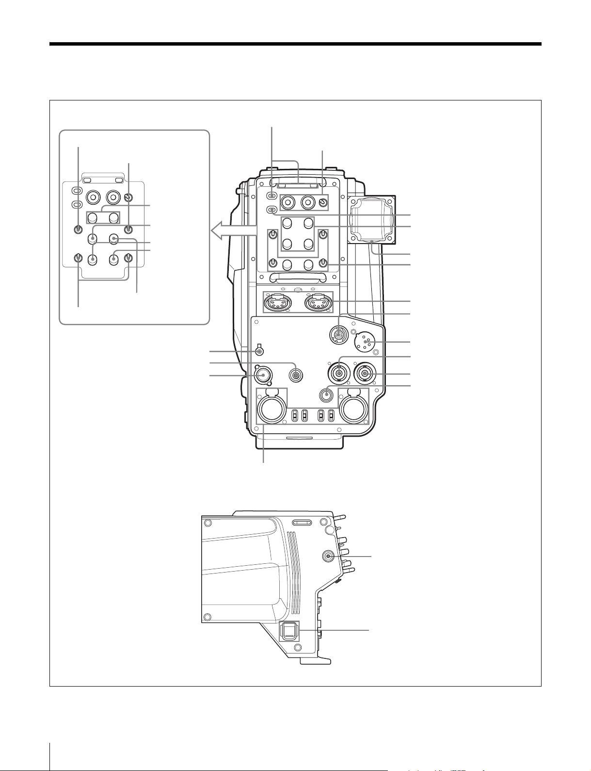
Function and Location of Parts and Controls
a TALLY lamp and TALLY switch
s LEVEL switch
Not used.
x MIC switches
p EARPHONE jack
o RET CTRL connector
n REMOTE connector
CA-590P
t PGM1/2
controls
u TRACKER
control
v ENG control
w PROD
control
Not used.
b RET 1 button, RET button and RET 2/3/4 switch
CA-590
c LIGHT switch
d PGM 1/2 level controls
e Triax connector
f INCOM level controls, PROD/
ENG switches, and MIC LEVEL
switches
g INCOM 1/2 connectos
h TRACKER connector
i DC IN connector
j RETURN connector
k PROMPTER connector
l DC OUT connector switch
m AUDIO IN CH 1/2 connectors, FRONT/REAR/LINE
switches, and MIC +48V/OFF/ · switches
q CALL button
r POWER switch
Function and Location of Parts and Controls
6
Page 7

a TALLY lamp and TALLY switch
When the TALLY switch is ON, the TALLY lamp lights
when a red tally signal, green tally signal, or call signal is
input from the CCU.
Turning the S101 switch on the internal AU-294 board to
ON mixes and outputs the battery alarm signal to the
TAL LY la m p.
b RET 1 button, RET button and RET 2/3/4 switch
RET1 (return video 1) button
While this button is pressed down, the return video1 signal
from the CCU (camera control unit) can be monitored in
the viewfinder or on a monitor connected to the RETURN
connector.
RET (return video) button
While this button is pressed down, the return video signal
from the CCU can be monitored in the viewfinder. Select
the monitored signal with the RET 2/3/4 switch.
RET 2/3/4 switch
Selects the return video signal to be monitored in the
viewfinder while the RET button is pressed down.
c LIGHT switch
Turns the backlight on the upper part of the panel and the
light on the connector section on or off. Depending on the
switch position, both lights turn on, only the light on the
connector section turns on, or both lights turn off.
d PGM (program audio) 1/2 level controls (for the
CA-590)
These controls adjust the audio volume of the program.
PGM level controls are provided for both intercom 1 and 2.
e Triax connector
Connects a CCU-550D/550DP/590/590P/700A/700AP/
790/790P Camera Control Unit through a triax cable.
f INCOM level controls, PROD/ENG switches, and
MIC LEVEL switches (for the CA-590)
OFF/REAR: Turns off the intercom microphone. Turn
the intercom microphone on and off using the control
on the external equipment connected to the RET
CTRL connector. Adjust the intercom reception level
with the INCOM level control.
OFF/FRONT: Turns off the intercom microphone. Turn
the intercom microphone on and off using the control
on the external equipment connected to the RET
CTRL connector or the VTR S/S switch on the video
camera. Use the control on the video camera to adjust
the intercom reception level. Depending on the video
camera, intercom reception level adjustment requires
menu operation.
g INCOM (intercom) 1/2 connectos
Connect headsets to enable the reception of program/
intercom audio and transmission of intercom audio.
Set the S3 switch on the internal MA-128 board to “CM”
when using headsets with a carbon-type microphone, and
set it to “DYN” when using headsets with a dynamic-type
microphone.
The INCOM 1 connector can be used for communications
through the engineer’s line even though the power to the
camera is turned off on the CCU-550D/550DP/590/590P/
700A/700AP/790/790P.
h TRACKER connector (10-pin)
Used for communications with a tracker and intercom 1
and 2 communications. Also outputs the up tally and
program audio signals. The maximam current output from
this connector is 500 mA. Settings regarding the input/
output signals can be made on the internal AU-294 board.
i DC IN (direct current input) connector (4-pin)
Connects an AC adapter or battery case. Supplies power
to the CA-590/590P when the POWER switch is set to
EXT.
j RETURN (return video output) connector (BNC
type)
Outputs the return video signal.
INCOM (intercom) level controls
These controls adjust the audio reception level of the
intercom 1/2.
PROD/ENG (producer/engineer) switches
Select the line for the microphone of the intercoms
connected to the respective INCOM connectors.
PROD: Selects the producer’s line.
ENG: Selects the engineer’s line.
MIC/LEVEL (microphone/intercom level) switches
The MIC and LEVEL settings specify the following
functions:
ON/REAR: Turns on the intercom microphone. Adjust
the intercom reception level with the INCOM level
control.
k PROMPTER (prompter video signal input/output)
connector (BNC type)
Inputs and outputs a prompter video signal. Use the S301
switch on the DM-139 internal board to select the
transmission direction (input or output) of the prompter
video signal. When the setting is made on the camera
adaptor, the transmission direction must be also changed
on the CCU.
l DC OUT (direct current output) connector (4-pin)
Outputs a direct current of 10.5 V to 17 V at a maximum
rated current output of 1.5 A. Connecting equipment with
a power consumption greater than the maximum rating
will activate the protection circuit, cutting off the current
flow.
Function and Location of Parts and Controls
7
Page 8

m AUDIO IN CH 1/2 connectors, FRONT/REAR/
LINE switches, and MIC +48V/OFF/• switches
AUDIO IN (audio input) CH 1/2 connectors (XLR type,
3-pin)
These connectors input external audio signals.
FRONT/REAR/LINE (audio signal selection) switches
These switches make settings for the respective audio
signals input from the AUDIO IN CH 1/2 connectors.
FRONT: Selects the audio input from the video camera as
the audio signal.
REAR: Outputs the audio signal input from the AUDIO
IN connector to the CCU. Gain control setting for the
connected microphone must be made on the CCU.
LINE: Sets the level for the signal input from the AUDIO
IN connector to –20 dB.
MIC +48V/OFF/• (microphone power supply mode)
switches
The following power supply settings can be specified for
the external microphone:
MIC +48V: +48 V is supplied to the external microphone
through the AUDIO IN connector. Set to this position
when the microphone requires +48 V of power supply.
OFF: No power is supplied through the AUDIO IN
connector.
• : +12 V is supplied to the external microphone through
the AUDIO IN connector. Set to this position when the
microphone requires +12 V of power supply. This
position becomes selectable when the S2 switch on the
MA-128 internal board is set to ON (page 9).
Note
Supplying power whose voltage does not match the
requirement to the microphone may damage the
microphone. Be sure to set the MIC +48V/OFF/• switches
to match the power requirement of the microphones.
n REMOTE connector (8-pin)
Connects an RCP-750/751/920/921 Remote Control Panel
or RM-B150 Remote Control Unit. Connection must be
made with a cable of 150 feet (50 meters) or less in length.
Notes
• The REMOTE connector cannot be used when a CCU is
connected.
• When connecting the RM-B150, use the cable supplied
with the RM-B150.
o RET CTRL (return control) connector (6-pin)
Inputs the control signal for selecting the return video and
for turning the intercom microphone on and off.
q CALL button
Use this button to call the CCU or MSU (master setup unit)
operator. When this button is pressed, the red tally lamps
in the viewfinder and on the CCU or MSU light up.
r POWER switch
Selects the power supply.
CCU: Power is supplied from the CCU.
OFF: Standby mode.
EXT: Power is supplied from the DC IN connector.
s LEVEL (intercom level) switch (for the CA-590P)
Selects the reception level adjustment method for the
intercoms connected to the INCOM 1/2 connectors.
REAR: Select this position to adjust the reception level of
the intercoms using the PGM1/2 controls, TRACKER
control, ENG control, and PROD control
independently.
FRONT: When this position is selected, audio volume of
the program, reception level of the intercom connected
to the TRACKER connector, and the reception level of
the engineer's line and the producer's line are adjusted
at one operation using the control on the video camera.
t PGM1/2 controls (for the CA-590P)
These controls adjust the audio volume of the program.
PGM1 control adjusts the program audio input from the
INCOM1 connector and the PGM2 control adjusts the
program audio input from the INCOM2 connector.
u TRACKER control (for the CA-590P)
Adjusts the reception level of the intercom connected to
the TRACKER connector.
v ENG (engineer) control (for the CA-590P)
Adjusts the reception level of the engineer's line.
w PROD (producer) control (for the CA-590P)
Adjusts the reception level of the producer's line.
x MIC (microphone level) switches (for the CA-590P)
Select the connection line of the intercom microphone
independently for the intercoms connected to the INCOM
1/2 connectors.
PROD: Connects the intercom microphone to the
producer's line.
ENG: Connects the intercom microphone to the
engineeer's line.
OFF: Cuts the intercom microphone connection.
p EARPHONE jack (mini-jack)
Connects an earphone for monitoring the audio from the
intercom or the program. Select the audio source with the
S251 and S252 switches on the internal AU-294 board.
Function and Location of Parts and Controls
8
Page 9
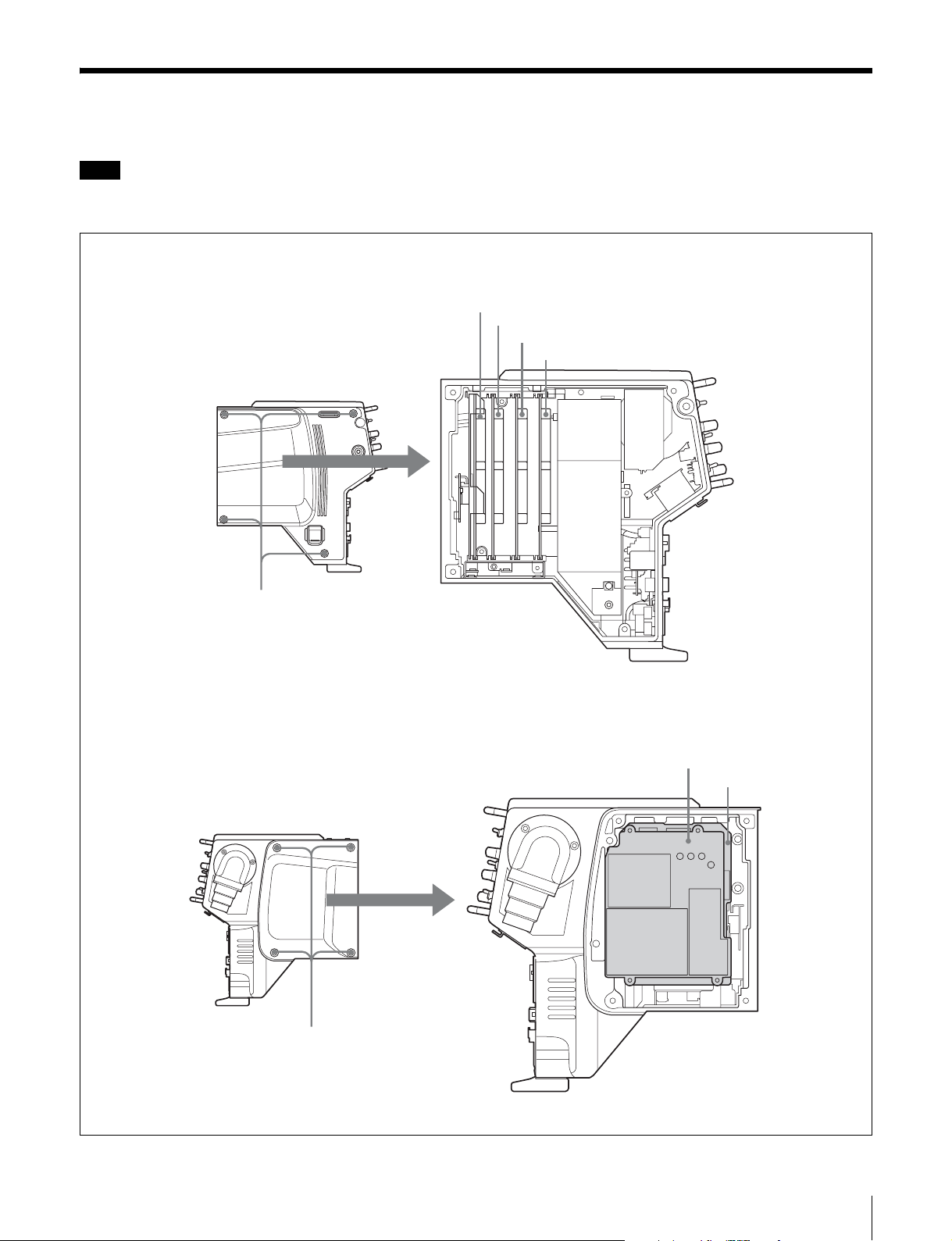
Internal Boards and Switch Settings
Note
To reduce the risk of electric shock, fire or injury, do not open the cabinet. To adjust the internal settings, refer to qualified
service personnel.
MD-132 board (no switches)
a TR-132 board
b MA-128 board
c AU-294 board
CA-590/590P
Unscrew the four screws.
CA-590/590P
Unscrew the four screws.
d DM-139 board
e MB-1019 board
Internal Boards and Switch Settings
9
Page 10
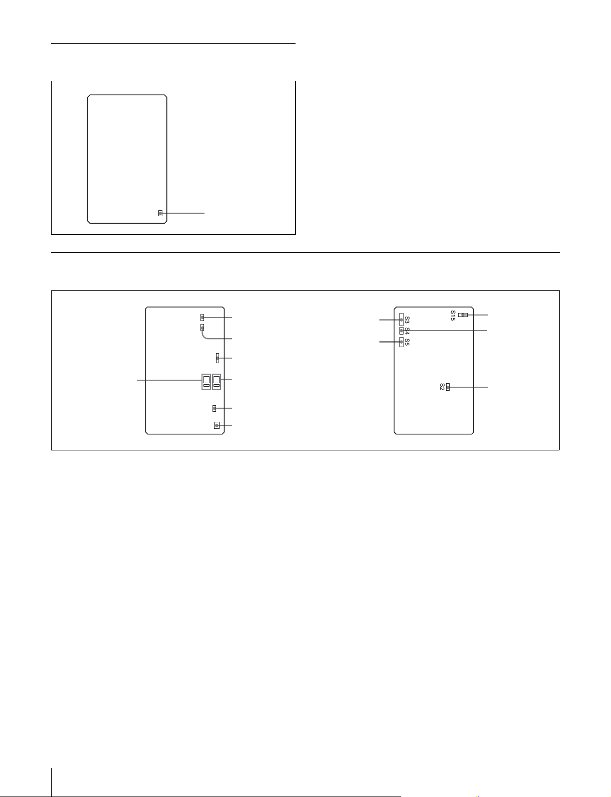
a TR-132 board
A S1 switch
Available in near future. Set this switch to OFF.
S1
A S1 switch
b MA-128 board
H S8 switch
S6 S8
K S13/S14 switches
A S1 switch
Available in near future. Set this switch to OFF.
F S6 switch
G S7 switch
S7
J S11/S12 switches
S14 S13
S12 S11
I S10 switch
S10
A S1 switch
S1
C S3 switch
E S5 switch
qs S15 switch
D S4 switch
B S2 switch
– : Sets the gain 6 dB below the standard level.
Normally, set this switch to 0.
B S2 switch
Set to ON only when supplying AC power to the
microphones connected to the AUDIO IN CH 1/2
connectors. Normally, set this switch to OFF.
C S3 switch
Set according to the microphone type of the headset
connected to the INCOM 1 connector.
DYN: Dynamic-type microphone
CM: Carbon-type microphone
D S4 switch
Set to ON when an unbalanced-type headset is connected
to the INCOM 1 connector.
E S5 switch
Sets the gain for the headset connected to the INCOM 1
connector.
+ : Sets the gain 6 dB above the standard level.
0 : Standard level.
Internal Boards and Switch Settings
10
F S6 switch
When set to ON, the audio signals input from the AUDIO
IN CH 1/2 connectors are mixed to the imtercom audio and
output to the INCOM 1 connector. This switch is factoryset to OFF.
G S7 switch
When set to ON, the audio signal input from the
TRACKER connector is mixed to the imtercom audio and
output to the INCOM 1 connector. Normally, set this
switch to OFF (center position).
H S8 switch
Specifies whether the VR of the INCOM 1 is used for
serial mix or parallel mix. Normally, set this switch to OFF.
I S10 switch
This switch is used for the intercom system connected to
the INCOM 1 connector. Normally, set this switch to
NORM.
Page 11
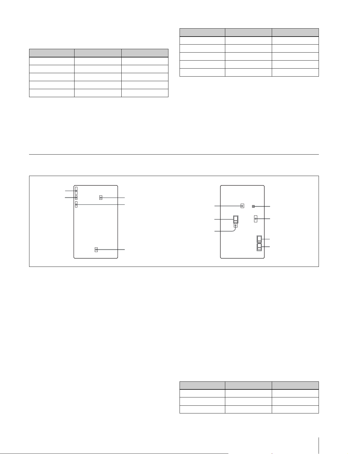
J S11/S12 switches
These switches select the audio to be mixed with the audio
output to the INCOM 1 connector.
Switch Audio to be mixed Normal setting
S11-1 Audio from INCOM 1 ON
S11-2 Audio from INCOM 2 OFF
S11-3 Program audio 1 OFF
S11-4 Program audio 2 OFF
S12 Tracker audio ON
Switch Audio to be mixed Normal setting
S13-1 Audio from INCOM 1 OFF
S13-2 Audio from INCOM 2 OFF
S13-3 Program audio 1 ON
S13-4 Program audio 2 ON
S14 Tracker audio OFF
When a one ear headset is used, set the S13-1 and S13-2
switches to ON.
When a one ear headset is used, set the S11-3 and S11-4
switches to ON.
K S13/S14 switches
These switches select the audio to be mixed with the
program audio output to the INCOM 1 connector.
c AU-294 board
A S3 switch
B S4 switch
S3 S4 S5
S201
S10
J S201 switches
C S5 switch
F S10 switch
L S15 switch
Set according to the broadcast system.
OFF: NTSC (for the CA-590)
ON: PAL (for the CA-590P)
I S101 switch
K S251/S252 switches
L S253 switches
S101
S251
S252
S253
S7
S13
S14
S11
S12
D S7 switch
E S8 switch
S8
H S13/S14 switches
G S11/S12 switches
A S3 switch
Set according to the microphone type of the headset
connected to the INCOM 2 connector.
DYN: Dynamic-type microphone
CM: Carbon-type microphone
B S4 switch
Set to ON when an unbalanced-type headset is connected
to the INCOM 2 connector.
C S5 switch
Sets the gain for the headset connected to the INCOM 2
connector.
+ : Sets the gain 6 dB above the standard level.
0 : Standard level.
– : Sets the gain 6 dB below the standard level.
Normally, set this switch to 0.
D S7 switch
When set to ON, the audio signal input from the
TRACKER connector is mixed to the imtercom audio and
output to the INCOM 2 connector. Normally, set this
switch to OFF (center position).
E S8 switch
Specifies whether the VR of the INCOM 2 is used for
serial mix or parallel mix. Normally, set this switch to OFF.
F S10 switch
This switch is used for the intercom system connected to
the INCOM 2 connector. Normally, set this switch to
NORM.
G S11/S12 switches
These switches select the audio to be mixed with the audio
output to the INCOM 2 connector.
Switch Audio to be mixed Normal setting
S11-1 Audio from INCOM 1 OFF
S11-2 Audio from INCOM 2 ON
S11-3 Program audio 1 OFF
Internal Boards and Switch Settings
11
Page 12
Switch Audio to be mixed Normal setting
S11-4 Program audio 2 OFF
S12 Tracker audio OFF
Switch Audio to be output
S253-4 Program audio 2
When a one ear headset is used, set the S11-3 and S11-4
switches to ON.
H S13/S14 switches
These switches select the audio to be mixed with the
program audio output to the INCOM 2 connector.
Switch Audio to be mixed Normal setting
S13-1 Audio from INCOM 1 OFF
S13-2 Audio from INCOM 2 OFF
S13-3 Program audio 1 ON
S13-4 Program audio 2 ON
S14 Tracker audio OFF
When a one ear headset is used, set the S13-1 and S13-2
switches to ON.
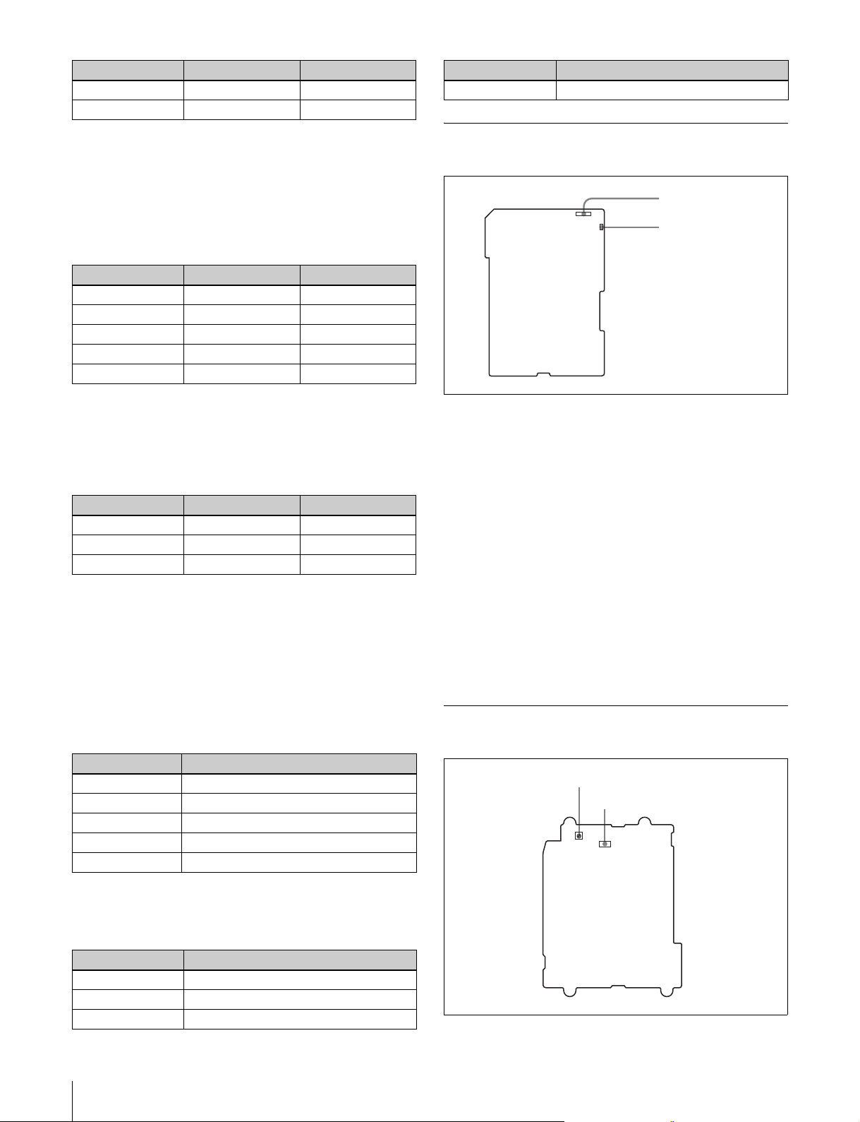
I S101 switch
Selects the item to be mixed with the battery alarm signal.
Switch Item to be mixed Normal setting
S101-1 Battery alarm signal ON
S101-2 TEMP OFF
S101-3 FAN STOP OFF
J S201 switches
Sets the talk level through the TRACKER connector.
– 20: Decreases the level by 20 dB.
0 : Standard level.
Normally, set this switch to 0.
d DM-139 board
A S301 switch
S1
S2
A S301 switch
Selects the direction of the prompter signal flow. The
signal flow direction must also be changed on the CCU.
RX: The video signal from the CCU is output from the
PROMPTER connector (factory-setting).
REM: Available in near future.
TX: The video signal input to the PROMPTER connector
is output to the CCU. Note that the CCU-550D/550DP
does not support this function.
B S302 switch
Selects the signal to be output from the PROMPTER
connector.
PROMPT: Prompter video signal is output (factory-
setting).
RET: Return video signal is output.
B S302 switch
K S251/S252 switches
These switches select the audio to be output to the
EARPHONE jack.
Switch Audio to be output
S251-1 Audio from INCOM 1
S251-2 Audio from INCOM 2
S251-3 Program audio 1
S251-4 Program audio 2
S252 Not used.
L S253 switches
These switches select the audio to be output to the
TRACKER connector.
Switch Audio to be output
S253-1 Audio from INCOM 1
S253-2 Audio from INCOM 2
S253-3 Program audio 1
Internal Boards and Switch Settings
12
e MB-1019 board
A S1 switch
B S2 switch
S301
S302
Page 13

A S1 switch
Selects the signal to be output to the RETURN connector.
RET: Return video signal is output (factory-setting).
MONI: Monitor video signal is output.
VBS: Composite video signal is output.
B S2 switch
Selects the signal to be input/output from the PROMPTER
connector.
PROMPT: Prompter video signal is input and output
(factory-setting).
REF: Reference signal for the video camera is input.
Internal Boards and Switch Settings
13
Page 14
Preparations
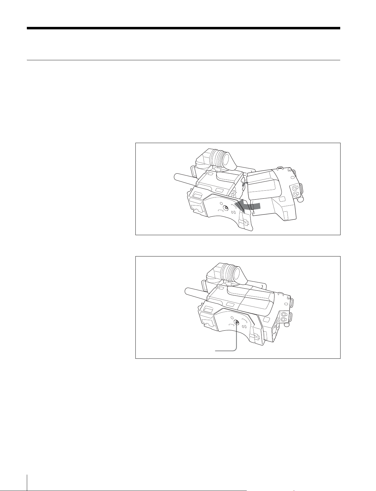
Attaching the CA-590/590P to a BVP-E10/E10P/E10WS/E10WSP/E30/E30P/ E30WS/E30WSP Color Video Camera
When you attach the CA-590/590P to a BVP-E10/E10P/E10WS/E10WSP/E30/
E30P/E30WS/E30WSP Color Video Camera as shown below, the 68-pin
connectors on both units are automatically connected.
1
Attach the CA-590/590P to the rear of the color video camera.
Hook the upper part, then push the lower part in until it snaps into place.
Removing a Camera Adaptor
2
Tighten the screw with a coin.
Tighten the screw.
Loosen the screw on the video camera until it stops, then remove the camera
adaptor while pushing the screw.
14
Preparations
Page 15
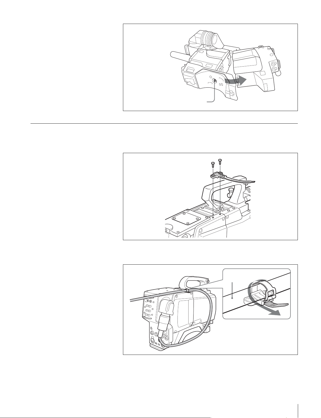
Loosen the screw on the video
camera until it stops, then push it.
Securing the triax cable to the camera adaptor
1
Attach the supplied cable holder with the supplied two M3 × 6 screws.
Cable holder
(supplied)
2
Route the triax cable as illustrated below, then fasten the cable holder
M3 × 6 screws (supplied)
around the cable.
cable
Preparations
15
Page 16

Removing the cable from the cable holder
Pull
Lift to release
16
Preparations
Page 17

Connections
Connectable equipment
CCU-700A/700AP/790/790P
Camera Control Unit
CCU-550D/550DP/590/590P
Camera Control Unit
RM-B750 Remote
Control Unit
BVF-55/55CE 5-inch Viewfinder
To the CAMERA
connector
To the triax
connector
Triax cable
To the REMOTE
connector
Camera cable
RCP-750/751/920/921 Remote
Control Panel
Power supply
When a Camera Control Unit is connected
Set the POWER switch to CCU to supply power to the CA590/590P from the CCU.
To the DC IN
connector
DC cord
AC-DN10 AC
Adaptor
To the DC OUT
connector
To supply power from the DC connector
Set the POWER swicth to EXT.
Connections
17
Page 18
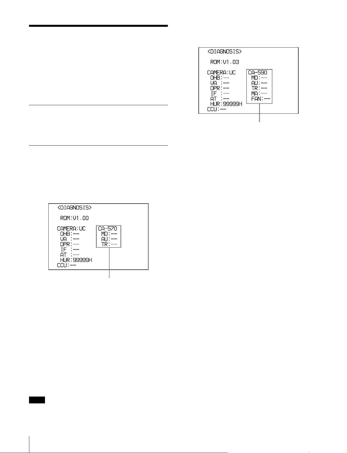
Self-Diagnostics
When the CA-590/590P is connected to the BVP-E10/
E10P/E10WS/E10WSP/E30/E30P/E30WS/E30WSP, you
can display the results of self-diagnostics of the CA-590/
590P internal boards using the DIAGNOSIS menu of the
video camera. The self-diagnostics results can be
monitored on the camera's viewfinder.
Displaying the DIAGNOSIS menu
For the BVP-E30/E30P/E30WS/E30WSP whose
camera software version is 1.03 or later
Refer to the Operating Instructions supplied with the video
camera.
The contents of the self-diagnostics results
For the BVP-E10/E10P/E10WS/E10WSP or for the
BVP-E30/E30P/E30WS/E30WSP whose camera
software version is earlier than 1.03
Self-diagnostics results of the CA-590/590P
internal boards
Self-diagnostics results of the CA-590/590P
internal boards
CA-590: Model name of the CA
MD: Status of the internal MD board
AU: Status of the internal AU board
TR: Status of the internal TR board
MA: Status of the internal MA board
FA N: Status of the fan on the CA power unit
CA-570: Model name of the CA (appears as "CA-570"
even when the CA-590/590P is connected).
MD: Status of the internal MD board
AU: Status of the internal AU board
TR: Status of the internal TR board
When an abnormality is detected, "NG" appears for the
corresponding internal board.
When an abnormality is detected on the fan of the CA
power unit, "- -" and "NG" alternate on all the internal
board status indications.
And when "NG" appears on all the internal board status
indications, an abnormality may have occurred on the CA
power unit.
Note
The camera software upgrade can be done only on the
BVP-E30/E30P/E30WS/E30WSP.
Self-Diagnostics
18
Page 19

Specifications
General
Power consumption
8 W (within the CA-590/590P)
Operating temperature
–20°C to +45°C (–4°F to +113°F)
Storage temperature
–20°C to +50°C (–4°F to +122°F)
Dimensions 120 × 211 × 202 mm (w/h/d)
Mass 2.8 kg (6 lb 3 oz)
Input/output connectors
AUDIO IN CH 1/2 (2ch)
DC IN XLR type, 4-pin, DC 10.5 to 17 V
DC OUT
RETURN BNC type, 1Vp-p, 75 ohms
PROMPTER BNC type, 1Vp-p, 75 ohms
RET CTRL 6-pin
EARPHONE Mini-jack, 8 ohms
CAMERA I/F 68-pin
CCU Triax
INCOM 1/2 (2ch)
REMOTE 8-pin
TRACKER 10-pin
∗
3
(4
/4 × 83/8 × 8 inches)
XLR type 3-pin, Female, 600 ohms,
balanced
4-pin, DC 10.5 to 17V, Max. 1.5 A
XLR type, 5-pin, Female
Design and specifications are subject to change without
notice.
Note
Always verify that the unit is operating properly before
use. SONY WILL NOT BE LIABLE FOR DAMAGES
OF ANY KIND INCLUDING, BUT NOT LIMITED
TO, COMPENSATION OR REIMBURSEMENT ON
ACCOUNT OF THE LOSS OF PRESENT OR
PROSPECTIVE PROFITS DUE TO FAILURE OF
THIS UNIT, EITHER DURING THE WARRANTY
PERIOD OR AFTER EXPIRATION OF THE
WARRANTY, OR FOR ANY OTHER REASON
WHATSOEVER.
∗ When a 5-inch viewfinder is connected to this unit or the
TRACKER connector or the REMOTE connector is used, the
maximum 1.5 A DC output cannot be obtained from the DC OUT
connector.
Supplied accessories
Carrying belt (1)
Cable holder (2)
M3 × 6 screws (4)
Operation Manual (1)
CD-ROM (1)
Optional accessories
CAC-6 Return Video Selector
BVF-55/55CE Viewfinder
RM-B750 Remote Control Unit
Specifications
19
Page 20

Page 21

The material contained in this manual consists of information
that is the property of Sony Corporation and is intended solely
for use by the purchasers of the equipment described in this
manual.
Sony Corporation expressly prohibits the duplication of any
portion of this manual or the use thereof for any purpose other
than the operation or maintenance of the equipment described
in this manual without the express written permission of Sony
Corporation.
Page 22

CA-590/590P
(UC/CE)
3-869-644-02 (1)
Sony Corporation
Printed in Belgium
2007.04.08
© 2005
 Loading...