

Page 1

CAMERA ADAPTOR
CA-570
CA-570P
電気製品は、安全のための注意事項を守らないと、火災
警告
このオペレーションマニュアルには、事故を防ぐための重要な注意事項と製
品の取り扱いかたを示してあります。このオペレーションマニュアルをよく
お読みのうえ、製品を安全にお使いください。お読みになったあとは、いつ
でも見られるところに必ず保管してください。
OPERATION MANUAL
や人身事故になることがあります。
Japanese/English/German
1st Edition (Revised 1)
Serial No. 15001 and Higher (UC)
Serial No. 35001 and Higher (J)
Serial No. 45001 and Higher (CE)
Page 2
安全のために
電気製品は、安全のための注意事項を守らないと、火災や感電などにより死
亡や大けがなど人身事故につながることがあり、危険です。
事故を防ぐために次のことを必ずお守りください。
安全のための注意事項を守る
2 (J) 〜3 (J) ページの注意事項をよくお読みください。
定期点検を実施する
長期間安全に使用していただくために、定期点検を実施することをおすすめ
します。点検の内容や費用については、ソニーのサービス担当者または営業
担当者にご相談ください。
故障したら使用を中止する
ソニーのサービス担当者、または営業担当者にご連絡ください。
万一、異常が起きたら
1 電源を切る。
異常な音、に
•
おい、煙が出
たら
落下させたら
•
/
2 トライアックスケーブルやDC電源接続コード
およびVTR 接続コードを抜く。
3 ソニーのサービス担当者、または営業担当者に
修理を依頼する。
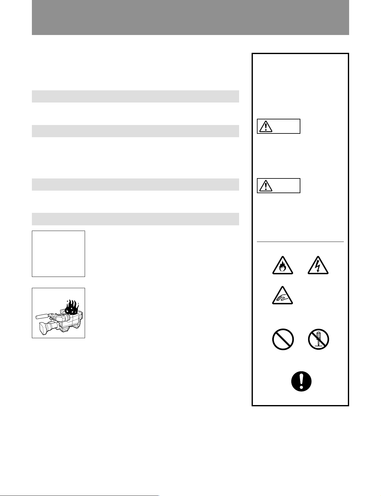
警告表示の意味
このオペレーションマニュアル
および製品では、次のような表
示をしています。表示の内容を
よく理解してから本文をお読み
ください。
警告
この表示の注意事項を守らない
と、火災や感電などにより死亡
や大けがなど人身事故につなが
ることがあります。
注意
この表示の注意事項を守らない
と、感電やその他の事故により
けがをしたり周辺の物品に損害
を与えたりすることがあります。
注意を促す記号
火災
感電
炎が出たら
すぐに電源を切り、消火する。
/
指挟み
行為を禁止する記号
禁止
行為を指示する記号
強制
分解禁止
Page 3

目次
警告 .....................................................................................................................2(J)
注意 .....................................................................................................................3(J)
概要 ..........................................................................................................................4(J)
各部の名称と働き ...................................................................................................
内部スイッチの設定................................................................................................
準備 .......................................................................................................................
カラービデオカメラBVP-950 への取り付け ..............................................12(J)
カラービデオカメラBVP-550 への取り付け ..............................................13(J)
付属のケーブルホルダーの使いかた........................................................... 14(J)
接続 .......................................................................................................................
接続できる機器............................................................................................... 15(J)
電源について................................................................................................... 16(J)
仕様 .......................................................................................................................
5(J
8(J
12(J
15(J
17(J
)
)
)
)
)
日
本
語
1 (J)
Page 4
警告
分解禁止
禁止
下記の注意を守らないと、
感電火災
火災や感電により死亡や大けがにつながることがあります。
分解しない、改造しない
分解したり、改造したりすると、感電の原因となります。
内部に水や異物を入れない
水や異物が入ると火災や感電の原因となります。
万一、水や異物が入ったときは、すぐに電源を切り、トライアックスケーブ
ルや接続コードを抜いて、ソニーのサービス担当者または営業担当者にご相
談ください。
禁止
禁止
強制
トライアックスケーブルや
トライアックスケーブルやDC電源ケーブルを傷つけると、火災や感電の原
因となります。
・ ケーブルを加工したり、傷つけたりしない。
・ 重いものをのせたり、引っ張ったりしない。
・ 熱器具に近づけたり、加熱したりしない。
・ ケーブルを抜くときは、必ずプラグを持って抜く。
万一、ケーブルが傷んだら、ソニーのサービス担当者に交換をご依頼くださ
い。
電源ケーブルを傷つけない
DC
油煙、湯気、湿気、ほこりの多い場所では設置•使用しない
上記のような場所で設置・使用すると、火災や感電の原因となります。
指定された
指定以外のCCU を使用すると、火災や感電の原因となります。
CCU (
カメラコントロールユニット)を使用する
2 (J)
Page 5
注意
下記の注意を守らないと、
けがをしたり周辺の物品に損害を与えることがあります。
カメラ側の固定ねじを締める
カメラと一体化して運用するときは、カメラの固定ねじをしっかり締めてく
強制
指挟み
ださい。固定ねじを締めずに使用するとカメラとカメラアダプターが分離
し、落下した機器でけがをすることがあります。
回転式トライアックスコネクターは慎重に扱う
回転式トライアックスコネクターを乱暴に扱うと、コネクター部が回転して
指を挟むことがあります。ケーブルの接続および取り外しは無理な力をかけ
ずに慎重に行ってください。
指定された外部機器を接続する
指定以外の機器を接続すると、火災や感電の原因となります。
強制
3 (J)
Page 6

概要
コンポーネント伝送方式
低消費電力
本機は、カラービデオカメラBVP-950およびBVP-550と一体化し、トライアックスケーブル
でカ メラコントロ ールユニットCCU-700AシリーズまたはCCU-550シリーズと接続するための
カメ ラアダプターです。
また、 BVP-950およびBVP-550とポータブルVTRBVW-50/DVW-250と接続するためのア
ダプターとしても使用できま す。
本機は以下のような特長を持っています。
Y/R−Y/B−Y信号による伝送を行います。
AC/DCコンバーターの効率向上によって、消費電力は約11Wです。
感電防止機能
各種入出力コネクターを装備
接続が不完全なとき、CCU(カメラコ ントロールユニット)からの高電圧供給が停止します。
• DC電源入出力コネクター
•リターンビデオ 1、 2、3、4を切り換える リターンコン トロールコネク ター
• プロンプター信号/外部同期信号入力コネクター
• RCP接続コネクター
• VTR接続コネクター
• インカムコネクタ ー (2系統)
• オ ーディオ(ライン/マイク切り換えスイッチ 付き) 入力コネク ター (2系統)
• TESTビデオ/RETビデオ出力コネクター
• イ ヤホンジャッ ク
•トラッカー 端 子
4 (J)
Page 7
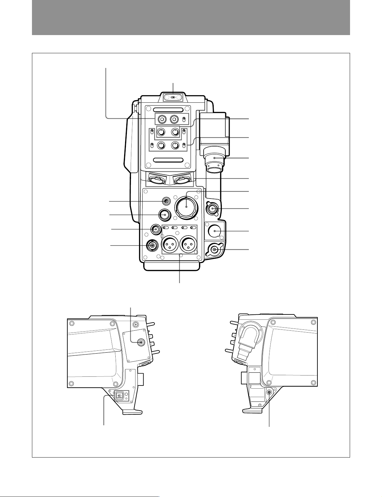
各部の名称と働き
!∞ EARPHONE
!¢ TRACKER
!£ RET CONT
!™ TEST OUT
1 RET1
ジャック
コネクター
コネクター
コネクター
ボタン/
RET
ボタンと
2 TALLY
RET 2/3/4
ランプと
スイッチ
TALLY
スイッチ
3 PGM
4 INCOM
5
6 INCOM 1/2
7 VTR
8 REMOTE
9 DC IN
0 PROMPTER/GEN LOCK
レベル調整つまみ
レベル調整つまみ、
スイッチと
ENG
トライアックスコネクター
コネクター
コネクター
コネクター
LEVEL/MIC
コネクター
PROD/
スイッチ
コネクター
!¶ POWER
!¡
!§ CALL
スイッチとインジケーター
ボタン
AUDIO IN 1/AUDIO IN 2
マイク電源供給モード切り換えスイッチ
コネクターと
!• DC OUT
LINE/MIC
コネクター
スイッチ/外部
5 (J)
Page 8

各部の名称と働き
1
RET1
押している間、カメ ラコ ン トロールユニットからのリ ターンビデ オ1 信
号をビューファ イ ンダー画面またはテストアウト信号でモニター でき
ます。
RET
押している間、カメラコ ン トロールユニットからのリ ターンビ デオ信号
をビューフ ァイ ンダー画面でモニターでき ます。モニターする信号
は、RET2/3/4スイッチで切り換えます。
RET 2/3/4
RETボタンを押したとき、ビューフ ァイ ンダー画面でモニターす る信
号を選択 します。
2
TALLYスイッチをONにすると、CCU側からレッドタリー信号および
コール信号を受信した場合にTALLYランプが点灯します。
AU-251基板上のS200-1スイッチを切り換えることにより、タリー 信
号にバ ッテリーアラーム信号をミックスすることが できます。
3
インターカム1/2それぞれに対応するつまみがあります。
プログラム音声の受信レベルを調整します。
(リターンビデオ1)ボタン/
RET1
オ)ボタンと
(リターンビデオ1)ボタン
(リターンビデオ)ボタン
TALLY
(プログラム)レベル調整つまみ
PGM
RET 2/3/4
スイッチ
(タリー)ランプと
スイッチ
TALLY
(リターンビデ
RET
スイッチ
LEVEL/MIC
LEVELスイッチとMICスイッチの組み合わせで、次のように設定
します。
REAR/ON:インターカムのマイク をONに します。受信レベルは、
INCOMつまみで調整します。
REAR/OFF:インターカムのマイ クをOFFにします。インターカム
のマイクのON/OFFは、RETCONTコネクター に接続した機
器で切り換えます。受信レベルは、INCOMつまみで調整し
ます。
FRONT/OFF:インターカムのマイ クをOFFにします。インターカ
ムのマイクのON/OFFは、RETCONTコネクターに接続した
機器で切り換えます。受信レベルは、カメラ側で調整します。
トライアックスコネクター
5
トライアックスケーブルでCCU-700AシリーズまたはCCU-550シリー
ズのカメラコントロールユニットに 接 続します 。
INCOM
6
ヘッドセットのプラグを差し込むと、プログラ ム/イ ンターカ ム音声の
受信およびインターカム音声の送信ができます。
カーボン タイ プのヘッドセ ットのときは、AU-237基板のMICスイッチ
をCMの位置に、ダイナミックタイプのときはDYNの位置に設定し
てく ださい。
インタ ーカム1コネク タ ーは、CCU側でカメラの電源を切っても、通
話できます。
(インターカムレベル/マイク)スイッチ
(インターカム)
コネクター
1/2
INCOM
4
ENG
MIC
インターカム1/2それぞれに対応する、つまみとス イッチがあ ります。
INCOM
インターカム音声の受信レベルを調整します。
PROD/ENG
インターカムライ ンを切り換えます。
PROD: プロデュ ーサー ラインを使用する とき。
ENG:エンジニアライ ンを使用する とき。
(インターカム)レベル調整つまみ、
(プロデューサー/エンジニア)スイッチと
(インターカムレベル/マイク)スイッチ
(インターカム)レベル調整つまみ
(プロデューサー/エンジニア)スイッチ
PROD/
LEVEL/
6 (J)
コネクター(26ピン)
VTR
7
映像信号、音声信号、コン トロール信号、電源などの入出力コネク
ターです。
VTRやACアダプターのCAMERAコネクターと接続します。
ご注意
CCUと接続しているときは、使用できません。
REMOTE
8
リモー トコン トロールパネルRCP-700シリーズおよびRM-B150を接
続します。接続時のケーブルの長さは、最長50mです。
ご注意
• CCUと接続しているときは、使用できません。
• RM-B150を接続するときは、RM-B150に付属のケーブルを使用
してください。
DC IN (DC
9
AC アダプターまたはバッテリ ーを接続します。
POWERスイッチがEXTのときに電源を供給します。
(リモート)コネクター(8ピン)
電源入力)コネクター(4ピン)
Page 9

0 PROMPTER/GEN LOCK
外部同期信号入力)コネクター(
外部同期信号の入力およびプロンプタービデオ入出力信号用のコ
ネクターです。内部のMD-119基板のPROMPTER/GENLOCK
スイ ッチを切り換えることにより、外部同期信号入力として使用する
か、プロンプタービデオ入出力として使用す るかを選択します。工
場出荷時は、PROMPTに設定されています。
AUDIO IN 1/AUDIO IN 2
!¡
ター(
XLR型3
イッチ/外部マイク電源供給モード切り換えスイッチ
外部から音声を入力します。入力信号の種類に応じて、LINE/
MICスイッチを切り換え ます。
外部マイクへの電源供給モードは、次の3種類を選択できます。
:外部マイクに12V電源を供給します。(AU-251基板のS800ス
•
イッチをONにしたときのみ有効です。)
:外部マイク に電源を供給しません。
OFF
:外部マイクに48V電源を供給します。(AU-251基板の
+
48V
S700スイッチをONにしたときのみ有効です。)
TEST OUT
!™
リターンビデオ信号、再生ビデオ信号、VBS信号、モニター出力信
号のいずれかを出力します。通常は、CCU接続時にリターンビデ
オ信号、VTR接続時に再生ビデオ信号を出力します。
ピン)と
(テストビデオ出力)コネクター(
(プロンプター信号入出力
型)
BNC
(オーディオ入力)コネク
LINE/MIC
(ライン/マイク)ス
BNC
/
型)
EARPHONE
!∞
イヤホンを接続すると、VTRからの音声、インターカムの音 声、プロ
グラムの音声を切り換えてモニターする ことができます。切り換え
は、MB-783基板上のS1スイッチで行います。
(コール)ボタン
CALL
!§
押すと、CCUやMSU(マスターセットアップユニット)、ビュー ファイ
ンダーのレ ッドタリーランプが点灯します。CCUやMSUのオペレー
ターを呼び出すときに使います。
POWER (電源)
!¶
電源の供給源を選びます。
u
g
1
!• DC OUT
DC10.5V〜17V、最大500mAの電源出力コネクターです。
消費電流が500mA以上の機器を接続すると、保護回路が動作し
ます。
:CCUから電源が供給されます。
CCU
(スタンバイ):スタ ンバイ状態になり ま す。
:VTRまた はDCINコネクターから電源が供給されます。
EXT
(イヤホン)ジャック
スイッチ
(DC電源出力)コネクター(4ピン)
ご注意
AU-251基板上のS100スイッチを切り換えるこ とにより、出力信号を
選択することができます。
!£
RET CONT
ン)
リターンビデオ選択信号とインターカムマイクのON/OFF制御信号
の入力コネク ターです。
TRACKER
!¢
このコネクターを介して、カメ ラマンとトラッ カ ーとの通話およびイン
ターカム 1、 2の送受信ができます。また、アップタ リー 信 号 とプロ グ
ラムオーディオ信号を出力します。この端子 から供給できる電源電
流は最大で500mAです。
(リターンコントロール)コネクター(6ピ
(トラッカー)コネクター(10ピン)
7 (J)
Page 10
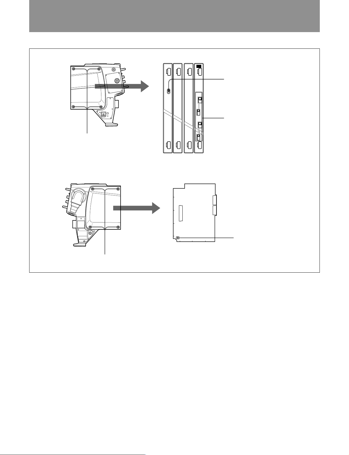
内部スイッチの設定
CA-570
MD TF AU AU
取り付けネジ4本をゆるめます。
CA-570
PROMPTER
GENLOCK
MB-783
A
B
C
D
E
S1
1234
INTERCOM
2
CM
DYN
GAIN
+
0
–
INTERCOM
1
CM
DYN
GAIN
+
0
–
基板上のスイッチ
CN10
CN25
CN11
1 PROMPTER/GENLOCK
2 INTERCOM
3 S1
スイッチと
スイッチ
GAIN
スイッチ
スイッチ
取り付けネジ4本をゆるめます。
1
PROMPTER/GENLOCK (
部同期信号入力
スイッチ(
)
プロンプター信号入出力/外
MD-119
基板)
PROMPT/GENLOCKコネクターの働きを切り換えます。
PROMPTER
GENLOCK
:プロンプター信号を入出力する。
:外部同期信号を入力します。
工場出荷時は、PROMPTERです。
2
INTERCOM
ン)スイッチ(
(インターカム)スイッチと
AU-237
基板)
GAIN
(ゲイ
INCOM1コネクターとINCOM2コネクターに接続するヘッドセ ッ
トのマイクに合わせて、それぞれ切り換えます。また、各マイクのゲ
インを切 り換え ます。
INTERCOM
:カーボン型マイ クの場合
CM
DYN
(インターカム)1/2スイッチ
:ダ イナミック型 マイクの場合
工場出荷時は、CMです。
(ゲイン)1/2スイッチ
GAIN
+:標準ゲインに対して、約 6dB大き くなります。
:標準ゲイン。
0
−:標準ゲインに対して、約 6dB 小さ くなります。
MB-783
3
基板のS1スイッチ
EARPHONEジャックから出力する音声の種類を設定します。
• S1-1:ONにすると、プログラム音声を出力します。
• S1-2:ONにすると、インターカム 2 の音 声を出 力します。
• S1-3:ONにすると、インターカム 1 の音 声を出 力します。
• S1-4:ONにすると、VTRの再生音を出力します。
工場出荷時は、S1-1のみがONです。
8 (J)
Page 11
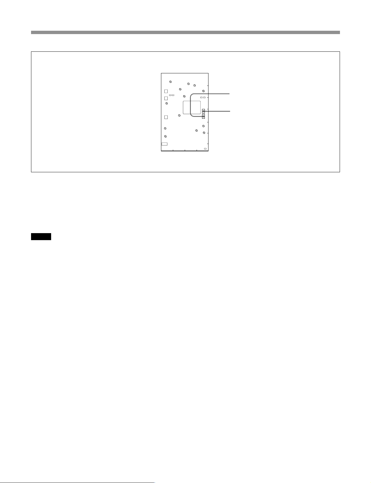
DM-116
基板上のスイッチ
LV3
CN5
TP4
E1
CN4
FL5
CN3
FL1
LV1
CN2
4 DM-116
基板のS1スイッチ
PROMPTER/GENLOCKコネクターの働きを切り換えます。
PROMPTER
GENLOCK
:プロンプター信号を入出力する。
:外部同期信号を入力します。
工場出荷時は、PROMPTERです。
ご注意
このスイッチは工場検査時に使用します。通常はMD-119基板の
PROMPTER/GENLOCKスイッチで切り換えます。
DM-116
5
基板のS4スイッチ
プロンプター信号の伝送方向を切り換えます。
CCU→CAM
: CCUから送られてきた映像信号を、
PROMPTER/GENLOCKコネクターから出力します。
CAM→CCU
:PROMPT/GENLOCKコネクターに入力した
映像信号を、CCU側に出力します。
RV3
LV4
RV2
FL3
A
FL4
RV4
B
E2
TP5
C
S4
D
S1
FL2
E
LV2
RV1
F
TP3
G
1234
6 AU-237
スイッチ
4 S1
スイッチ
5 S4
基板のS3スイッチ
INCOM2コネクターから出力す るインカム音声とプログラム音声の
ミックス方 法を 切り換えます。
:ミックスしない。
IND
:ミックスモード2(S5スイッチで設定)になる。
MIX
工場出荷時の設定は、INDです。(PALでは、MIX)
AU-237
7
基板のS4スイッチ
ONにすると、プログラム音声にインカム音声がミックスされます。
工場出荷時はOFFです。
AU-237
8
基板のS2スイッチ
INCOM1コネクターから出力す るインカム音声とプログラム音声の
ミックス方 法を 切り換えます。
:ミックスしない。
IND
:ミックスモード1(S4スイッチで設定)になる。
MIX
工場出荷時の設定は、INDです。(PALでは、MIX)
AU-237
9
基板の
S302
スイッチ
INCOM2コネクターのRTSモードとNORMALモードを切り換えま
す。
工場出荷時は、NORMALです。
AU-237
0
基板の
S411
スイッチ
TRACKERコネクターを介したトークレ ベ ルを 設 定します 。
:標準
0 dB
−
:20dB減(入力レベルが大きいときに設定してくださ
20 dB
い。)
9 (J)
Page 12
内部スイッチの設定
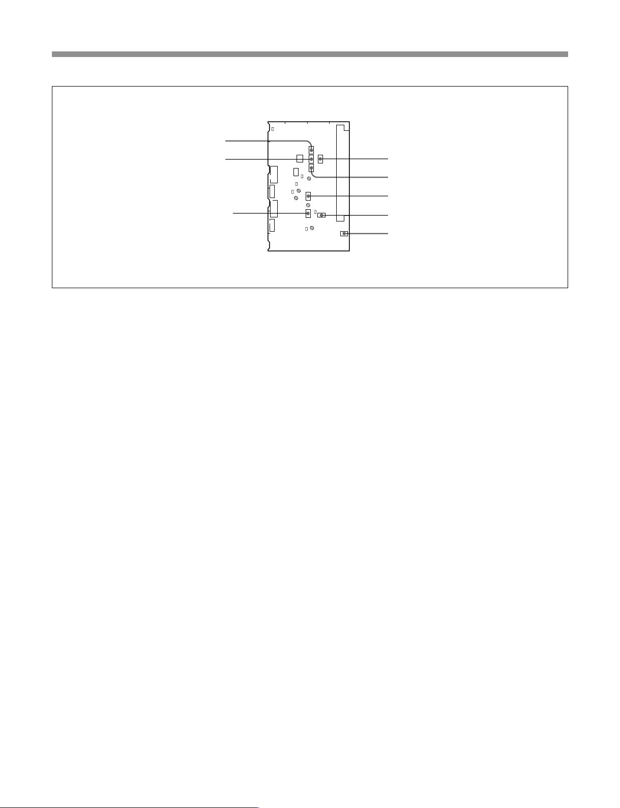
基板上のスイッチ
E451
A
B
S362
C
E301
S363
TP301
RV111
D
S182
E
S183
F
!¡ AU-237
基板の
S181
6 S3
!£ S5
!™ S111
スイッチ
AU-237
スイッチ
スイッチ
スイッチ
INCOMコネクターに接続したヘッドセットのダイナミ ックマイクをア
ンバランスで使用するとき、ノイズ防止のためにYピンをGNDに接
続する場合に使用します。
S181-1
S181-2
:INTERCOM1のMICYピンをGNDに接続する。
:INTERCOM2のMICYピンをGNDに接続する。
1234
S3
S301
S4S5
S2
S1
E1
RV301
RV112
S111
RV411
E111
RV302
S302
TP111
S411
!∞
CN1
S181
AU-251
基板の
スイッチ
7 S4
スイッチ
8 S2
9 S302
0 S411
!¡ S181
S600
スイッチ
スイッチ
スイッチ
スイッチ
マイク1入力をカメラ側からとるか、本機のAUDIOIN1コネクター
から とるかを選択します。
:カメラ側のMIC1 コネクタ ーから とる。
C
:本機のAUDIOIN1コネクターからとる。
CA
工場出荷時の設定は、CAです。
!™ AU-237
基板の
S111
スイッチ
INCOM1コネクターのRTSモードとNORMALモードを切り換えま
す。
工場出荷時は、NORMALです。
AU-237
!£
基板のS5スイッチ
O N に すると、インカム音声にプログラム音声が ミックスされます。
工場出荷時は、OFFです。
AU-251
!¢
基板の
S800
スイッチ
外部マイクへの電源供給(12V)をON/OFFします。ただし、後
面パネルのMIC電源スイッチがOFFまたは48Vのときは、電源供
給されません。
工場出荷時は、OFFです。
AU-251
!§
基板の
S351
スイッチ
マイク入力をヘッドセットでモニターするときONにします。工場出
荷時の設定は、OFFです。
AU-251
!¶
基板の
S700
スイッチ
外部マイクへの電源供給(48V)をON/OFFします。
AU-251
!•
基板の
S200
スイッチ
• S200-1:ONにすると、TALLYランプにバッテリーアラーム信号が
ミックスされます。 工場出荷時の設定は、OFFです。この設定で、
ビューフ ァインダー内の表示は影響されません。
• S200-2:CCU接続時、REMOTEコネクターから電源を供給する
かど う かを選択します。
:CCU接続時は自動的に電源供給を OFFにし、スタンドア
ON
ローン時はONにする。
:常に電源を供給する。
OFF
工場出荷時は、ONです。
10 (J)
Page 13
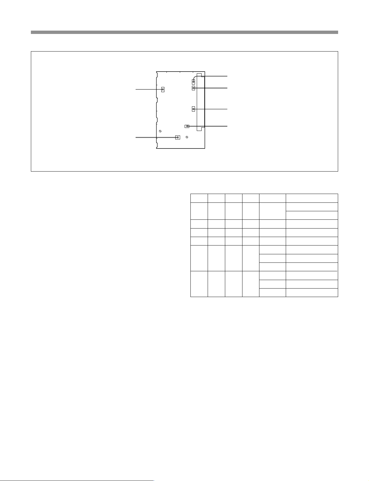
!¢ S800
スイッチ
AU-251
基板上のスイッチ
4 3 21
A
S800
B
S600
S351
!∞ S600
!§ S351
スイッチ
スイッチ
C
D
RV220
E
スイッチ
F
!ª AU-251
基板の
S100
!ª S100
スイッチ
TESTOUTコネクターから出力される信号を切り換えます。
• S100-1:再生ビデオ信号とリターンビデオ信号の自動切り換えを
禁止するためのスイッチです。
:強制的に再生ビデオ信号が出力される。
ON
:CCU接続時にはリターンビデオ信号が出力され、VTRが
OFF
接続されているときは再生ビデオ信号が出力される。
工場出荷時の設定は、OFFです。
• S100-2:VBS出力信号とリターン/再生ビ デ オ信号を切り換える
スイ ッチです。
:カメ ラからのVBS信号を出力する。
ON
:リターンまたは再生ビデオ信号を出力する。
OFF
工場出荷時の設定は、OFFです。
• S100-3:RETCONTコネクターからの制御信号を受け付けるかど
うかを選択します。
:リターンコン トロール信号が L になったときのみ、リターンビ
ON
デオ信号を出力する。
:CCU接続時のみ、リターンビデオ信号を出力する。
OFF
• S100-4:VBSビデオ出力とモニター出力を切り換えます。
:モニター出力信号を出力する。
ON
:VBS信号を出力する。
OFF
CN1
S700
S200
S100
RV100
!¶ S700
!• S200
スイッチ
スイッチ
S100スイッチの設定とビデオ出力信号の関係は、次のとおりです。
S100-1 S100-2 S100-3 S100-4
RET CONT
OFF OFF ― ― ―
ON OFF ― ― ― 再生ビデオ
― ON OFF OFF ― VBSビデオ
― ON ON OFF ― モニタービデオ
OFF ON OFF ON L
OFF ON ON ON L
ビデオ出力信号
リターンビデオ(CCU接続時)
再生ビデオ(VTR接続時)
リターンビデオ(CCU接続時)
L
再生ビデオ(VTR接続時)
H VBSビデオ
リターンビデオ(CCU接続時)
L
再生ビデオ(VTR接続時)
Hモニタービデオ
11 (J)
Page 14
準備
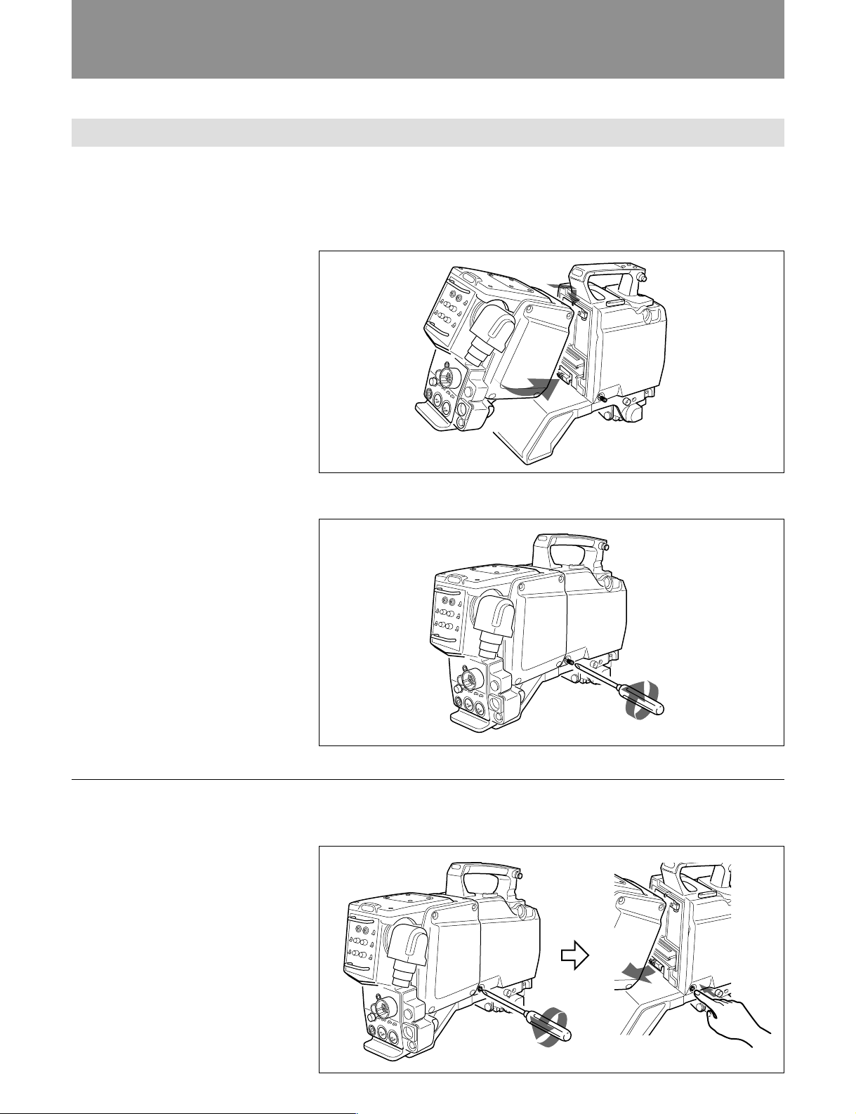
カラービデオカメラ
BVP-950
への取り付け
以下のように組み立てると、BVP-950とCA-570の68ピンコネク ター同士が接続されます。
1 BVP-950後部にCA-570を取り付ける。
上部を先に引っかけてから、下部の端子部をカチッと手ごたえがするまで押し込みます。
2 ド ライ バーなどでネジを締める。
BVP-950
ネジを締める
から取り外すには
BVP-950のネジをゆるめて、押しながらCA-570を取り外します。
12 (J)
Page 15
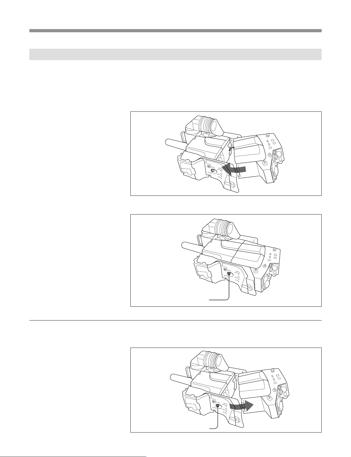
カラービデオカメラ
BVP-550
への取り付け
以下のように組み立てると、BVP-550とCA-570の68ピンコネク ター同士が接続されます。
1 BVP-550後部にCA-570を取り付ける。
上部を先に引っかけてから、下部の端子部をカチッ と手ごたえがする まで押し込みま
す。
2 コイ ンなどでネジ を締める。
BVP-550
ネジを締める
から取り外すには
BVP-550のネジを止まるところまでゆるめて、押しながらCA-570を取り外します。
ネジを止まるところ
までゆるめて、押す。
13 (J)
Page 16
準備
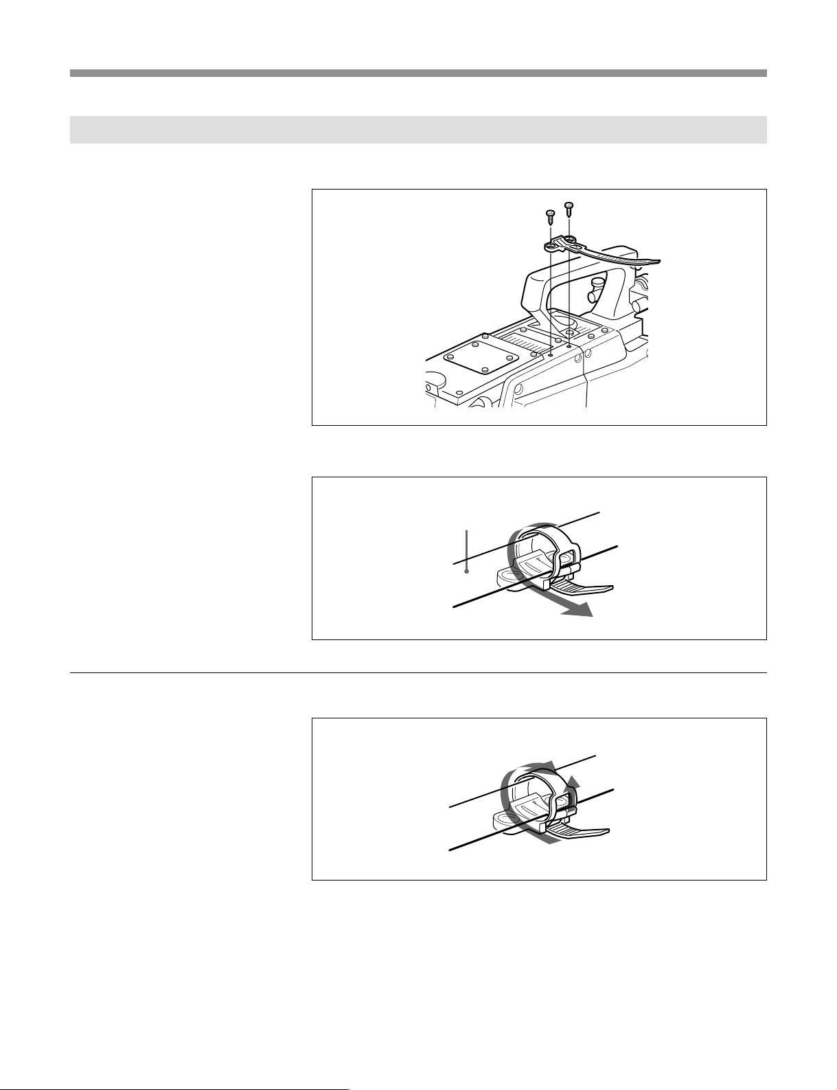
付属のケーブルホルダーの使いかた
1 付属のM3ネジ (2本) で、 ケ ー ブルホルダー を取 り付ける。
M3ネジ(付属)
ケーブルホルダー
2 ケーブルに巻きつける。
ケーブルホルダーからケーブルを外すには
ケーブル
引く
引き上げながら
14 (J)
Page 17
接続
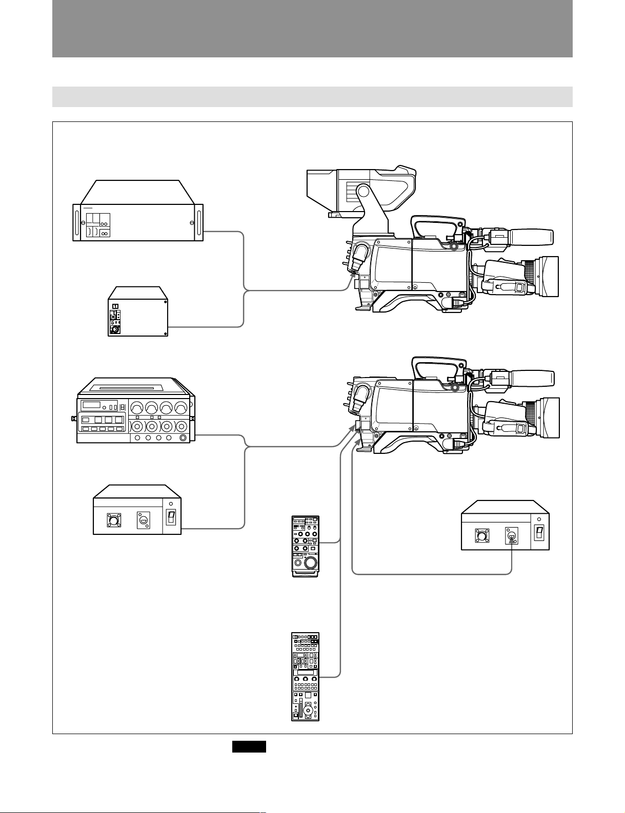
接続できる機器
カメラコントロールユニット
CCU-700
シリーズ
インチビューファインダー
5
BVF-55
カメラコントロールユニット
CCU-550
1
u
ポータブル
VTR BVW-50/DVW-250
アダプター
AC
AC-550
CAMERA
CAMERA
コネクター
(26ピン)
コネクターへ
トライアックス
コネクターへ
トライアックスケーブル
VTR
へ
コネクター
(26ピン)
カメラケーブル
REMOTE
コネクターへ
リモートコントロール
ユニット
RM-B150
へ
DC IN
コネクターへ
アダプター
AC
AC-550
CAMERA
(14ピン)
コネクター
へ
コード
DC
(AC-550
に付属
)
DC OUT
コネクターへ
リモートコントロール
ユニット
RCP-700
シリーズ
7000 -3
2CCL1
••••
••
•
••
••
•
••••••
ご注意
CCU接続時は、VTRコネクターには何も接続しないでください。接続すると、回路が正常
に動作しません。
15 (J)
Page 18

接続
電源について
接続時
CCU
接続時
VTR
POWERスイッチをuCCU側に設定してください。
電源はCCUから供給されます。
コネクターから電源を供給するときは
DC IN
POWERスイッチを1EXT側に設定してください。
POWERスイッチを1EXT側に設定してください。 VTRから電源が供給されます。
VTR接続時、DCINコネクターに電源を接続した場合は、自動的に外部電源に切り換わり
ます。
ご注意
ビュ ー ファインダーBVF-55は消費電力が大きいため、ポータブルVTRから電源を供給する
ときは使用できません。
16 (J)
Page 19

仕様
一般
消費電力 11W
動作温度 −20℃〜+45℃
保存温度 −20℃〜+50℃
外形寸法 115×212×195mm(幅×高さ×奥行き)
質量 2.7kg
入出力コネクター
MICIN(2チャンネル)
XLR型3ピン、オス、600Ω、平衡
DCIN XLR型、4ピン、DC10.5〜17V
DCOUT 4ピン、DC10.5〜17V、最大500mA
GENLOCKIN BNC型、1Vp-p、75Ω
TESTOUT BNC型、1Vp-p、75Ω
RETCONT 6ピン
EARPHONE ミニジャック、8Ω
CAMERAI/F 68ピン
VTR CCZ型、26ピン
CCU トライアックス
INCOM(2チャンネル)
XLR型、5ピン、メ ス
REMOTE 8ピン
TRACKER 10ピン
別売り品
リターンビデオセレクター CAC-6
ビュー ファ インダー BVF-55
リモー トコン トロールユニット RM-B150
仕様および外観は、改良のため予告なく変更することがあります
が、ご了承ください。
付属品
キャ リングベルト(1)
ケーブルホルダー(2)
M3×6ネジ(4)
オペ レーションマニュアル(1)
メンテナンスマニュアル(1)
17 (J)
Page 20

Page 21

WARNING
To prevent fire or shock hazard, do not
expose the unit to rain or moisture.
To avoid electrical shock, do not open the
cabinet. Refer servicing to qualified
personnel only.
For the customers in the USA
This equipment has been tested and found to comply with
the limits for a Class A digital device, pursuant to Part 15 of
the FCC Rules. These limits are designed to provide
reasonable protection against harmful interference when the
equipment is operated in a commercial environment. This
equipment generates, uses, and can radiate radio frequency
energy and, if not installed and used in accordance with the
instruction manual, may cause harmful interference to radio
communications. Operation of this equipment in a residential
area is likely to cause harmful interference in which case the
user will be required to correct the interference at his own
expense.
You are cautioned that any changes or modifications not
expressly approved in this manual could void your authority
to operate this equipment.
English
The shielded interface cable recommended in this manual
must be used with this equipment in order to comply with the
limits for a digital device pursuant to Subpart B of Part 15 of
FCC Rules.
1(E)
Page 22

Table of contens
Table of Contents
Overview............................................................................................... 3(E)
Location and Function of Parts and Controls .................................. 4(E)
Internal Switch Settings ...................................................................... 8(E)
Preparations ....................................................................................... 12(E)
Attaching the CA-570/570P to a BVP-950/950P Color
Video Camera .....................................................................12(E)
Attaching the CA-570/570P to a BVP-550/550P Color
Video Camera .....................................................................13(E)
Using the Supplied Cable Holder..................................................14(E)
Connections ........................................................................................ 15(E)
Connectable Equipment ................................................................15(E)
Power Supply ................................................................................16(E)
Specifications...................................................................................... 17(E)
2(E)
Page 23

Overview
The CA-570/570P Camera Adaptor attaches to the BVP-950/950P or
BVP-550/550P Color Video Camera to allow the connection of a CCU700A or a CCU-550 Series Camera Control Unit through a triax cable.
The CA-570/570P can also be used to connect a BVW-50/50P/DVW-250/
250P Portable VTR to the BVP-950/950P or BVP-550/550P Color Video
Camera.
The CA-570/570P has the following features:
Component signal transmission system
The CA-570/570P transmits a component signal (Y/R–Y/B–Y) through a
triax cable.
Low power consumption
An AC/DC converter of higher efficiency than the previous model has
reduced power consumption to about 11 W.
Anti-electrical shock function
The high-voltage supply from the camera control unit (CCU) is cut when
the triax cable is not completed connected.
Variety of input/output connectors
The CA-570/570P is equipped with the following connectors:
•DC power input/output connector
•Input connector for remote-switching of return video 1, 2, 3, and 4
•Prompter signal/external sync signal input connector
•RCP connector
•VTR connector
•INCOM connector (2)
•AUDIO (LINE/MIC switch available) input connector (2)
•TEST/RET video output connector
•EARPHONE jack
•TRACKER connector
3(E)
Page 24

Location and Function of Parts and Controls
Location and Function of Parts and Controls
!ª PGM level control
@º ENG level control
@™ PROD level control
@£ TRACKER level control
@¢ LEVEL/MIC switch
!∞ EARPHONE jack
!¢ TRACKER connector
!£ RET CONT connector
!™ TEST OUT connector
CA-570P
@¡ MIC LINE
switch
1 RET1 button/RET button and RET 2/3/4 switch
2 TALLY lamp and TALLY switch
CA-570
3 PGM level controls and PROD/
ENG switches
4 INCOM level controls, PROD/ENG
switches, and LEVEL/MIC switches
5 Triax connector
6 INCOM 1/2 connector
7 VTR connector
8 REMOTE connectors
9 DC IN connector
!º PROMPTER/GEN LOCK connector
!§ CALL button
!¶ POWER switch and indicator
!¡ AUDIO IN 1/AUDIO IN 2 connectors and LINE/MIC switch
and external power supply mode switch for the microphone
!• DC OUT connector
4(E)
Page 25

1 RET1 (return video 1) button/RET (return
video) button and RET 2/3/4 switch
RET1 (return video 1) button
Press this button to monitor the return video1 signal
from the CCU in the viewfinder or on a monitor using
the TEST OUT signal .
RET (return video) button
Press this button to monitor the return video signal
from the CCU in the viewfinder. Select the monitored
signal with the RET 2/3/4 switch.
RET 2/3/4 switch
Selects the return video signal monitored in the
viewfinder while the RET button is pressed.
2 TALLY lamp and TALLY switch
When the TALLY switch is ON, the TALLY lamp
lights when a red tally signal or call signal is input
from the CCU.
Turning S200-1 on the AU-251 board to ON mixes
and outputs the battery alarm signal to the TALLY
lamp.
3 PGM (program) level controls (for the CA-570)
Adjusts the audio volume of the program.
Note
PGM level controls are provided for both intercom 1
and 2.
4 INCOM (intercom) level controls, PROD/ENG
(producer/engineer) switches, and LEVEL MIC
(intercom level/microphone) switches (for the
CA-570)
REAR/OFF: Turns off the intercom microphone.
Turn the intercom microphone on and off using
the control on the external equipment connected to
the RET CONT connector. Adjust the intercom
reception level with the INCOM control.
FRONT/OFF: Turns off the intercom microphone.
Turn the intercom microphone on and off using
the control on the external equipment connected to
the RET CONT connector. Use the control on the
camcorder to adjust the intercom reception level.
Note
INCOM level controls and LEVEL/MIC switches and
PROD/ENG switches are provided for both intercom 1
and 2.
5 Triax connector
Connects a CCU-700A/700AP or CCU-550/550P
Series Camera Control Unit through a triax cable.
6 INCOM (intercom) 1/2 connectors
Connects headphones to enable the reception of
program/intercom audio and transmission of intercom
audio.
Set the MIC switch on the AU-237 board to “CM”
when using a carbon-type headphone, and set it to
“DYN” when using a dynamic microphone.
The INCOM 1 connector can be used for
communications even though the power to the camera
is turned off on the CCU-700A/700AP or CCU-550/
550P.
7 VTR connector (26-pin)
Inputs and outputs video signals, audio signals, control
signals, and the power supply.
Connects with the CAMERA connector on a VTR or
AC adaptor.
INCOM (intercom) level controls
Adjusts the audio volume of the intercom.
PROD/ENG (producer/engineer) switches
Switches the intercom line.
PROD: Selects the producer’s line
ENG: Selects the engineer’s line
LEVEL/MIC (intercom level/microphone) switches
The LEVEL and MIC switch settings specify the
following functions:
REAR/ON: Turns on the intercom microphone.
Adjust the intercom reception level with the
INCOM control.
Note
The VTR connector cannot be used when a CCU is
connected.
8 REMOTE connector (8-pin)
Connects an RCP-700 Series or RM-B150 Remote
Control Unit. Connection must be made with a cable
of 150 feet (50 meters) or less in length.
Note
•The REMOTE connector cannot be used when a
CCU is connected.
•When connecting the RM-B150, use the cable
supplied with the RM-B150.
5(E)
Page 26

Location and Function of Parts and Controls
9 DC IN (direct current input) connector (4-pin)
Connects an AC adapter or battery case. Supplies
power to the CA-570/570P when the POWER switch
is set to EXT.
!º PROMPTER/GEN LOCK (prompter signal
input and output/external sync signal input)
connector (BNC type)
Inputs an external sync signal or inputs and outputs a
prompter video signal. Select the respective function
with the PROMPTER/GENLOCK switch on the
internal MD-119 board. The connector is factory set
for PROMPT.
!¡ AUDIO IN 1/AUDIO IN 2 (audio input)
connectors (XLR type, 3-pin) and LINE/MIC
(line input/microphone) switch
Inputs external audio signals. Set the LINE/MIC
switch according to the input signal type.
The following power supply settings can be specified
for the external microphone:
•: +12V is supplied to the external microphone
(when the S800 switch on the AU-251 biard is set
to ON).
OFF: No power is supplied to the external
microphone.
+48V: +48V is supplied to the external microphone.
(when the S700 switch on the AU-251 board is set
to ON).
!™ TEST OUT (test video output) connector (BNC
type)
Outputs return video signals, playback video signals,
VBS signal, or monitor output signals. Normally
outputs return video signals when a CCU is connected,
and playback video signals when a VTR is connected.
!∞ EARPHONE jack (mini-jack)
Connects an earphone for monitoring the audio from
the VTR, the intercom, or the program. Select the
audio source with the switch S1 on the MB-783 board.
!§ CALL button
Use this button to call the CCU or MSU operator.
When this button is pressed, the red tally lamps in the
viewfinder and on the camera control unit (CCU) or
master setup unit (MSU) light up.
!¶ POWER switch
Selects the power supply.
u CCU: Power is supplied from the CCU.
¬ (standby): Standby mode
1 EXT: Power is supplied from the VTR or EXT DC
IN connector.
!• DC OUT (direct current output) connector (4-
pin)
Outputs a direct current of 10.5 V to 17 V at a
maximum rated current output of 500 mA. Connecting
equipment with a power consumption greater than the
maximum rating will activate the protection circuit,
cutting off the current flow.
!ª PGM (program) level control (for the CA-570P)
Adjusts the audio volume of the program.
@º ENG (engineer) level control (for the CA-570P)
Adjusts the audio volume of the engineer.
@¡ MIC LINE switch (for the CA-570P)
PROD: Selects the producer’s line.
OFF: Turns off the microphone.
ENG: Selects the engineer’s line.
Note
Select the output signal with switch S100 on the AU251 board.
!£ RET CONT (return control) connector (6-pin)
Inputs the control signal for selecting the return video
and for turning the intercom microphone on and off.
!¢ TRACKER connector (10-pin)
Use for communications with a tracker and intercom 1
and 2 communications. Also outputs the up tally and
program audio signals. The maximam output current
output from this connector is 500 mA.
6(E)
@™ PROD (engineer) level control (for the CA-570P)
Adjusts the audio volume of the producer.
@£ TRACKER (engineer) level control (for the CA570P)
Adjusts the audio volume of the tracker.
Page 27

@¢ LEVEL/MIC (intercom level/microphone)
switch (for the CA-570P)
The LEVEL and MIC switch settings specify the
following functions:
REAR/ON: Turns on the intercom microphone.
Adjust the intercom reception level with the PGM
level control, ENG level control, PROD level
control, or TRAKER level control.
REAR/OFF: Turns off the intercom microphone.
Turn the intercom microphone on and off using
the control on the external equipment connected to
the RET CONT connector. Adjust the intercom
reception level with the PGM level control, ENG
level control, PROD level control, or TRAKER
level control.
FRONT/OFF: Turns off the intercom microphone.
Turn the intercom microphone on and off using
the control on the external equipment connected to
the RET CONT connector. Use the control on the
camcorder to adjust the intercom reception level.
7(E)
Page 28

Internal Swicth Settings
Internal Switch Settings
CA-570/570P
Unscrew the four screws.
MD TF AU AU
PROMPTER
GENLOCK
INTERCOM
2
CM
DYN
GAIN
+
0
–
INTERCOM
1
CM
DYN
GAIN
+
0
–
1 PROMPTER/GENLOCK switch
2 INTERCOM and GAIN switches
CA-570/570P
Unscrew the four screw
1 PROMPTER/GENLOCK (prompter signal
input and output/external sync signal input)
switch (MD-119 board)
Selects the PROMPT/GENLOCK connector function.
PROMPTER: Inputs and outputs a prompter signal
(factory setting).
GENLOCK: Inputs an external sync signal.
2 INTERCOM and GAIN switches (AU-237
board)
Set these switches to specify the type of microphone
connected to the INCOM 1 and INCOM 2 connectors
and their respective gain.
INTERCOM 1/2 switches
CM: carbon microphone (factory setting)
DYN: dynamic microphone
Switch on the MB-783 board
A
B
CN25
C
D
E
S1
1234
CN10
CN11
3 Switch S1
GAIN 1/2 switches
+: Raises the gain 6 dB above standard gain
0: Standard gain
–: Lowers the gain 6 dB below standard gain
3 Switch S1 on the MB-783 board
Specifies the type of audio signal output from the
EARPHONE jack.
•S1-1: Set to ON to output the program audio signal.
•S1-2: Set to ON to output the audio signal of
intercom 1.
•S1-3: Set to ON to output the audio signal of
intercom 2.
•S1-4: Set to ON to output the VTR playback audio
signal.
All switches are factory set to OFF, except S1-1.
8(E)
Page 29

Switch on the DM-116 board
LV3
CN5
TP4
CN4
FL5
CN3
FL1
LV1
CN2
RV3
LV4
E1
RV2
FL3
A
FL4
RV4
B
TP5
E2
C
S4
D
S1
FL2
E
LV2
RV1
F
TP3
G
1234
4 Switch S1
5 Switch S4
4 Switch S1 on the DM-116 board
Selects the PROMPT/GENLOCK connector function.
PROMPTER: Inputs and outputs a prompter signal
(factory setting).
GENLOCK: Inputs an external sync signal.
Note
Swicth S1 on the DM-116 board is used for factory
inspection use only.
The PROMPTER/GENLOCK connector function is
normally specified using the PROMPTER/GENLOCK
switch on the MD-119 board.
5 Switch S4 on the DM-116 board
Selects the direction of the prompter signal flow
between the CCU and CAM.
CCU→CAM: The video signal from the CCU is
output from the PROMPTER/GEN LOCK
connector.
CAM→CCU: The signal input to the PROMPT/
GEN LOCK connector is output to the CCU.
6 S3 switch on the AU-237 board
Specifies whether the incom audio output from
INCOM 2 connector and the program audio are mixed
or not.
IND: No mixing (factory setting for NTSC)
MIX: Mix mode 2 (set by switch S5) (factory setting
for PAL)
7 Switch S4 on the AU-237 board
When this switch is set to ON, the program audio is
mixed with the intercom audio. The factory setting is
OFF.
8 Switch S2 on the AU-237 board
Specifies whether the incom audio output from
INCOM 2 connector and the program audio are mixed
or not.
IND: No mixing (factory setting for NTSC)
MIX: Mix mode 1 (set by switch S4) (factory setting
for PAL)
9 Switch S302 on the AU-237 board
Sets the INCOM 2 connector to either RTS mode or
NORMAL mode. The factory setting is NORMAL
mode.
0 Switch S411 on the AU-237 board
Sets the talk level through the TRACKER connector.
0 dB: Standard level
–20 dB: Decreases the talk level by 20 dB. (Select
this setting when the input level is too high.)
9(E)
Page 30

Internal Swicth Settings
Switch on the AU-237 board
E451
A
6 Switch S3
!£ Switch S5
!™ Switch S111
B
S362
C
E301
S363
TP301
RV111
D
S182
E
S183
F
!¡ Switch S181 on the AU-237 board
When the dynamic microphone used for the incom
headset is unbalanced, this switch connects the MIC
pin Y to ground (GND) to prevent noise. The factory
setting is OFF.
S181-1: Connects the MIC pin Y of Incom 1 to
ground.
S181-2: Connects the MIC pin Y of Incom 2 to
ground.
!™ Switch S111 on the AU-237 board
Sets the INCOM 1 connector to either RTS mode or
NORMAL mode. The factory setting is NORMAL
mode.
!£ Switch S5 on the AU-237 board
When this switch is set to ON, the intercom audio is
mixed with the program audio. The factory setting is
OFF.
!¢ Switch S800 on the AU-251 board
Turns the power supply (12 V) to the external
microphone on and off. No power is supplied if the
MIC power switch on the rear panel is set to OFF or to
+48V. The factory setting is OFF.
1234
S3
S301
S4S5
S2
S1
E1
RV301
RV112
S111
RV411
E111
CN1
RV302
S302
TP111
S411
S181
7 Switch S4
8 Switch S2
9 Switch S302
0 Switch S411
!¡ Switch S181
!§ Switch S351 on the AU-251 board
Set to ON to monitor the microphone input on a
headset. The factory setting is OFF.
!¶ Switch S700 on the AU-251 board
Turns the power supply (48 V) to the external
microphone on and off.
!• Switch S200 on the AU-251 board
•S200-1: When S200-1 is set to ON, the battery alarm
signal is mixed with the tally lamp signal. This
switch is factory set to OFF. In this position, the
indicator in the viewfinder is unaffected.
•S200-2: When a CCU is connected to the CA-570/
570P, this switch specifies whether power is supplied
from the REMOTE connector or not.
ON: When a CCU is connected, the power is
automatically turned off. When the camera is
used as a stand-alone unit, the power is turned on
(factory setting).
OFF: The power is supplied from the REMOTE
connector.
!∞ Switch S600 on the AU-251 board
Specifies input of the audio input signal from the
MIC1 connector on the camcorder or the AUDIO IN 1
connector on the CA-570/570P.
C: Input from the MIC 1 connector on the
camcorder.
CA: Input from the AUDIO IN 1 connector on the
CA-570/570P.
10(E)
Page 31

!¢ Switch S800
Switch on the AU-251 board
4 3 21
A
S800
B
S600
S351
!∞ Switch S600
!§ Switch S351
C
D
RV220
E
!ª Switch S100
F
!ª Switch S100 on the AU-251 board
Selects the signal output from the TEST OUT
connector.
•S100-1: Disables automatic switching between the
playback video signal and the return video signal.
ON: Outputs the playback video signal.
OFF: Outputs the return video signal when a CCU is
attached; outputs the playback video signal when a
VTR is attached. The factory setting is OFF.
•S100-2: Specifies output of the VBS signal from the
camera or the return/playback video signal.
ON: Outputs the VBS signal from the camera.
OFF: Outputs the return or playback video signal.
The factory setting is OFF.
•S100-3: Selects whether the control signal from the
RET CONT connector is received or not.
ON: Outputs the return video signal only for an L
return control signal.
OFF: Outputs the return video signal only when a
CCU is connected.
•S100-4: Selects either a VBS video signal output or
monitor signal output.
ON: Outputs the monitor signal.
OFF: Outputs the VBS signal.
CN1
S700
S200
S100
RV100
!¶ Switch S700
!• Switch S200
The various combinations of switch S100 settings and
their corresponding video output signal are as follows:
S100-1 S100-2 S100-3 S100-4 RET
CONT
OFF OFF ———Return video
ON OFF ———Playback video
— ON OFF OFF — VBS video
— ON ON OFF — Monitor video
OFF ON OFF ON L Return video
OFF ON ON ON L Return video
Video output
signal
(when a CCU is
connected)
Playback video
(when a VTR is
connected)
(when a CCU is
connected)
L Playback video
(when a VTR is
connected)
H VBS video
(when a CCU is
connected)
L Playback video
(when a VTR is
connected)
H Monitor video
11(E)
Page 32

Preparations
Preparations
Attaching the CA-570/570P to a BVP-950/950P Color Video Camera
When you attach the CA-570/570P to a BVP-950/950P Color Video
Camera as shown below, the 68-pin connectors on both units are
automatically connected.
1 Attach the CA-570/570P to the rear of the BVP-950/950P.
Hook the upper part, then push the lower part in until it snaps into
place.
Removing a Camera Adaptor
2 Tighten the screw with a screwdriver.
Tighten the screw.
Loosen the screw on the video camera, then push it.
12(E)
Page 33

Attaching the CA-570/570P to a BVP-550/550P Color Video Camera
When you attach the CA-570/570P to a BVP-550/550P Color Video
Camera as shown below, the 68-pin connectors on both units are
automatically connected.
1 Attach the CA-570/570P to the rear of the BVP-550/550P.
Hook the upper part, then push the lower part in until it snaps into
place.
2 Tighten the screw with a coin.
Removing a Camera Adaptor
Tighten the screw.
Loosen the screw on the video camera until it stops, then remove the
camera adaptor while pushing the screw.
Loosen the screw on the video
camera until it stops, then push it.
13(E)
Page 34

Preparations
Using the Supplied Cable Holder
1 Attach the cable holder with the supplied two M3×6 screws.
2 Fasten the cable clamp around the cable.
M3×6 screws (supplied)
Cable holder
Removing the cable clamp
cable
pull
lift to release
14(E)
Page 35

Connections
Connectable Equipment
CCU-700A/700AP Series Camera Control Unit
To the CAMERA
connector
CCU-550/550P Series Camera Control Unit
1
u
BVF-55/55CE 5-inch Viewfinder
To the triax
cable connector
Triax cable
BVW-50/50P/DVW-250/250P Portable VTR
To the CAMERA
connector (26-pin)
AC-550/550CE AC Adaptor
To the CAMERA
connector (14-pin)
To the VTR
connector (26-pin)
Camera cable
To the REMOTE
connector
RM-B150
Remote Control Unit
RCP-700 series
Remote Control
Unit
7000 -3
To the DC IN connector
AC-550/550CE AC Adaptor
DC cord (supplied with
the AC-550/550CE)
2CCL1
To the DC OUT
connector
••••
••
•
••
••
•
••••••
Note
When a Camera Control Unit is connected, do not connect other
equipment to the VTR connector. If a Camera Control Unit and portable
VTR are connected simultaneously, the camera will not operate normally.
15(E)
Page 36

Connections
Power Supply
When a Camera Control Unit is connected
When the POWER switch is set to u CCU,
power is supplied from the CCU.
To supply a power from the DC connector
Set the POWER swicth to 1 EXT.
When a VTR is connected
When the POWER switch is set to 1 EXT,
Power is supplied from the VTR.
When the CA-570/570P is attached to the VTR and power is supplied from
the DC IN connector, external power supply is automatically selected.
Note
Due to the large power consumption of the BVF-55/55CE viewfinder, the
viewfinder cannot be used when power is being supplied from a portable
VTR.
16(E)
Page 37

Specifications
General
Power consumption
11 W
Operating temperature
–20°C to +45°C (–4°F to +113°F)
Storage temperature
–20°C to +50°C (–4°F to +122°F)
Dimensions 115 × 212 × 195 mm (w/h/d)
Mass 2.7 kg (5 lb 15 oz)
5
/8 × 83/8 × 73/4 inches)
(4
Input/output connectors
MIC IN (2ch) XLR type 3-pin, Female,
600 ohms, balanced
DC IN XLR type, 4-pin, DC 10.5 to 17 V
DC OUT 4-pin, DC 10.5 to 17V,
Max. 500 mA
GEN LOCK IN BNC type, 1Vp-p, 75 ohms
TEST OUT BNC type, 1Vp-p, 75 ohms
RET CONT 6-pin
EARPHONE Mini-jack, 8 ohms
CAMERA I/F 68-pin
VTR CCZ type, 26-pin
CCU Triax
INCOM (2ch) XLR type, 5-pin, Female
RCP 8-pin
Tracker 10-pin
Optional accessories
CAC-6 Return Video Selector
BVF-55/55CE Viewfinder
RM-B150 Remote Control Unit
Design and specifications are subject to change
without notice.
Supplied accessories
Carrying belt (1)
Cable holder (2)
M3 × 6 screws (4)
Operation manual (1)
Maintenance manual (1)
17(E)
Page 38

Page 39

VORSICHT
Um Feuergefahr und die Gefahr eines elektrischen
Schlages zu vermeiden, darf das Gerät weder Regen
noch Feuchtigkeit ausgesetzt werden.
Um einen elektrischen Schlag zu vermeiden, darf das
Gehäuse nicht geöffnet werden. Überlassen Sie
Wartungsarbeiten stets nur einem Fachmann.
Für Kunden in Deutschland
Dieses Produkt kann im kommerziellen und in begrenztem
Maße auch im industriellen Bereich eingesetzt werden.
Dies ist eine Einrichtung, welche die Funk-Entstörung
nach Klasse B besitzt.
Deutsch
1(G)
Page 40

Table of contens
Inhaltsverzeichnis
Kurzbeschreibung ...............................................................................3(G)
Lage und Funktion der Bedien- und Anzeigeteile ............................ 4(G)
Einstellung der internen Schalter ...................................................... 8(G)
Vorbereitungen .................................................................................. 11(G)
Anbringen des CA-570P an Farbvideokamera BVP-950P .......... 11(G)
Anbringen des CA-570P an Farbvideokamera BVP-550P .......... 12(G)
Nutzung des mitgelieferten Kabelhalters ..................................... 13(G)
Anschlüsse .......................................................................................... 14(G)
Mögliche Gerätekonfigurationen ................................................. 14(G)
Stromversorgung .......................................................................... 15(G)
Technische Daten...............................................................................16(G)
2(G)
Page 41

Kurzbeschreibung
Der Kameraadapter CA-570P ist für die Farbvideokamera BVP-950P oder
BVP-550P zum Anschluß einer Kamerasteuereinheit der Serie CCU-700A
oder CCU-550 über ein Triaxkabel bestimmt. Der CA-570P kann auch
zum Anschluß eines portablen Videorecorders BVW-50P/DVW-250P an
die Farbvideokamera BVP-950P oder BVP-550P dienen.
Der CA-570P hat die folgenden Merkmale:
System zur Übertragung von Komponentensignalen
Der CA-570P sorgt für die Übertragung eines Komponentensignals (Y/R–
Y/B–Y) über ein Triaxkabel.
Niedrige Leistungsaufnahme
Ein Wechselstrom-Gleichstrom-Wandler mit höherem Wirkungsgrad als
beim Vorgängermodell reduziert die Leistungsaufnahme auf ca. 11 W.
Stromschlag-Schutzfunktion
Die Hochspannung von der Kamerasteuereinheit (CCU) wird deaktiviert,
wenn das Triaxkabel nicht vollständig angeschlossen ist.
Vielzahl verschiedener Ein- und Ausgänge
Der CA-570P verfügt über die folgenden Anschlüsse:
•Gleichspannungs-Ein-/Ausgang
•Eingang zur Fernumschaltung der Rückführvideosignale 1, 2, 3 und 4
•Eingang für Promptersignal/externes Synchronsignal
•RCP-Anschluß
•VTR-Anschluß
•INCOM-Anschluß (2)
•AUDIO-Eingang (LINE/MIC-Umschaltung möglich) (2)
•TEST/RET-Videoausgang
•GGGEARPHONE jack
•TRACKER-Anschluß
3(G)
Page 42

Lage und Funktion der Bedien- und Anzeigeteile
Lage und Funktion der Bedien- und Anzeigeteile
1 RET1-Taste/RET-Taste und RET 2/3/4-Schalter
2 TALLY-Anzeige und TALLY-Schalter
!ª PGM-Pegelregler
!• LEVEL/MIC-Schalter
!¶ TRACKER-Pegelregler
!§ PROD-Pegelregler
!∞ EARPHONE-Buchse
!¢ TRACKER-Anschluß
!£ RET CONT-Anschluß
!™ TEST OUT-Anschluß
3 ENG-Pegelregler
4 MIC LINE-Schalter
5 Triaxanschluß
6 INCOM 1/2-Anschluß
7 VTR-Anschluß
8 REMOTE-Anschluß
9 DC IN-Anschluß
!º PROMPTER/GEN LOCK-
Anschluß
!¡ AUDIO IN 1/AUDIO IN 2-Anschluß und LINE/MIC-Schalter
sowie Schalter für externe Mikrofon-Stromversorgung
4(G)
@º CALL-Taste
@¡ POWER-Schalter und
zugehörige Anzeige
@™ DC OUT-Anschluß
Page 43

1 RET1-Taste (Rückführvideo 1)/RET-Taste
(Rückführvideo) und RET 2/3/4-Schalter
RET1-Taste (Rückführvideo 1)
Überwachung des Rückführvideosignals 1 von der
Kamerasteuereinheit im Sucher oder auf einem
Monitor mit dem TEST OUT-Signal.
RET-Taste (Rückführvideo)
Überwachung des Rückführvideosignals 1 von der
Kamerasteuereinheit im Sucher. Die Wahl des zu
überwachenden Signals erfolgt mit dem RET 2/3/4Schalter.
RET 2/3/4-Schalter
Wahl des im Sucher zu überwachenden
Rückführvideosignals, wenn die RET-Taste gedrückt
wird.
2 TALLY-Anzeige und TALLY-Schalter
Bei betätigtem TALLY-Schalter leuchtet die TALLYAnzeige auf, wenn von der Kamerasteuereinheit ein
Rot-Tallysignal oder ein Rufsignal eingeht.
Durch Stellen des Schalters S200-1 an Karte AU-251
auf ON wird das Batteriealarm-Signal zugemischt und
über die TALLY-Anzeige ausgegeben.
7 VTR-Anschluß (26pol)
Ein- und Ausgabe von Video-, Audio- und
Steuersignalen sowie der Stromversorgung.
Wird mit dem CAMERA-Anschluß an einem
Videorecorder oder Netzadapter verbunden.
Hinweis
Bei Anschluß einer Kamerasteuereinheit ist der VTRAnschluß funktionslos.
8 REMOTE-Anschluß (8pol)
Anschluß eines Fernsteuerpults RM-B150 oder der
Serie RCP-700 über ein Kabel, das eine Höchstlänge
von 50 Metern haben darf.
Hinweis
•Bei Anschluß einer Kamerasteuereinheit ist der
REMOTE-Anschluß funktionslos.
•Bei Anschluß eines RM-B150 verwenden Sie das
dem RM-B150 mitgelieferte Kabel.
9 DC IN-Anschluß (Gleichstromeingang) (4pol)
Anschluß eines Netzadapters oder eines
Akkubehälters. Ermöglicht die Stromversorgung des
CA-570P, wenn der POWER-Schalter auf EXT
gestellt ist.
3 ENG-Pegelregler (Techniker)
Einstellung der Lautstärke des Technikerkanals.
4 MIC LINE-Schalter
PROD: Wahl des Regisseurkanals
OFF: Ausschalten des Mikrofons
ENG: Wahl des Technikerkanals
5 Triaxanschluß
Anschluß einer Kamerasteuereinheit der Serie CCU700AP oder CCU-550P über ein Triaxkabel.
6 INCOM 1/2-Anschluß (Gegensprechen)
Anschluß von Kopfhörern zum Empfang von
Programm-/Gegensprechton und zum Senden von
Gegensprechton.
Bei Verwendung eines Kohlemikrofons stellen Sie den
MIC-Schalter an Karte AU-237 auf “CM” und bei
einem dynamischen Mikrofon auf “DYN”.
Der INCOM 1-Anschluß kann auch dann zur
Kommunikation dienen, wenn die Stromversorgung
der Kamera über CCU-700AP oder CCU-550P
ausgeschaltet worden ist.
!º PROMPTER/GEN LOCK-Anschluß (Ein-/
Ausgang für Promptersignal-/Eingang für
externes Synchronsignal) (BNC)
Eingang für ein externes Synchronsignal oder Ein-/
Ausgang für ein Promptersignal. Wahl der jeweiligen
Funktion mit dem PROMPTER/GEN LOCK-Schalter
an der internen Karte MD-119. Die werkseitige
Einstellung ist PROMPT.
!¡ AUDIO IN 1/AUDIO IN 2-Anschluß
(Audioeingänge) (XLR, 3pol) und LINE/MICSchalter (Eingang für hochpegeliges Signal/
Mikrofon)
Ein-/Ausgänge für Audiosignale. Der LINE/MICSchalter ist gemäß dem jeweiligen Eingangssignaltyp
einzustellen.
Für die Stromversorgung des externen Mikrofons sind
die folgenden Einstellungen möglich:
•: Betriebsspannung von +12 V für das externe
Mikrofon (Bei Schalter S800 auf ON an Karte
AU-251)
OFF: Keine Stromversorgung des externen
Mikrofons
+48V: Betriebsspannung von +48 V für das externe
Mikrofon (Bei Schalter S700 auf ON an Karte
AU-251)
5(G)
Page 44

Lage und Funktion der Bedien- und Anzeigeteile
!™ TEST OUT-Anschluß (Testvideoausgang)
(BNC)
Ausgang für das Rückführvideosignal, VideoWiedergabesignal, VBS-Signal oder Überwachungs-
Ausgangssignal. Normalerweise Ausgabe von
Rückführvideosignalen bei Anschluß einer
Kamerasteuereinheit und von VideoWiedergabesignalen bei Anschluß eines
Videorecorders.
Hinweis
Die Wahl des Ausgangssignals erfolgt mit Schalter
S100 an der Karte AU-251.
!£ RET CONT-Anschluß
(Rückführungssteuerung) (6pol)
Eingang für das Steuersignal zur Wahl des
Rückführvideosignals und zum Ein- und Ausschalten
des Gegensprechmikrofons.
!¢ TRACKER-Anschluß (10pol)
Zur Kommunikation mit einem Tracker und über die
beiden Gegensprechkanäle 1 und 2. Außerdem
Ausgang für das Up-Tally-Signal und das ProgrammAudiosignal. An diesem Anschluß läßt sich ein
maximaler Ausgangsstrom von 500 mA abgreifen.
!∞ EARPHONE-Buchse (Miniklinke)
Anschluß eines Ohrhörers zur Überwachung der
Audiosignale von Videorecorder, Gegensprechkanälen
oder Programm. Wahl der Audiosignalquelle mit
Schalter S1 an Karte MB-783.
REAR/OFF: Ausschalten des
Gegensprechmikrofons.
Zum Ein- und Ausschalten des
Gegensprechmikrofons betätigen Sie das
entsprechende Funktionselement am externen
Gerät, das an den RET CONT-Anschluß
angeschlossen ist.
Die Einstellung des Gegensprechempfangspegels
erfolgt mit dem PGM-Pegelregler, ENGPegelregler, PROD Pegelregler oder TRACKERPegelregler.
FRONT/OFF: Ausschalten des
Gegensprechmikrofons.
Zum Ein- und Ausschalten des
Gegensprechmikrofons betätigen Sie das
entsprechende Funktionselement am externen
Gerät, das an den RET CONT-Anschluß
angeschlossen ist.
Die Einstellung des Gegensprechempfangspegels
erfolgt mit dem PGM-Pegelregler, ENGPegelregler, PROD Pegelregler oder TRACKERPegelregler an der Kamera.
!ª PGM-Pegelregler (Programm)
Einstellung der Lautstärke des Programmkanals.
@º CALL-Taste
Rufen des Bedieners an der Kamerasteuereinheit oder
Master-Setup-Einheit. Bei Drücken dieser Taste
leuchten die roten Tally-Anzeigen im Sucher und an
der Kamerasteuereinheit oder der Master-SetupEinheit auf.
!§ PROD-Pegelregler (Regisseur)
Einstellung der Lautstärke des Regisseurkanals.
!¶ TRACKER-Pegelregler (Techniker)
Einstellung der Lautstärke des Trackerkanals.
!• LEVEL/MIC-Schalter (Gegensprechsignalpegel/
Mikrofon)
Über die verschiedenen Stellungen der LEVEL/MICSchalter lassen sich folgende Funktionen aufrufen:
REAR/ON: Einschalten des Gegensprechmikrofons.
Die Einstellung des Gegensprechempfangspegels
erfolgt mit dem PGM-Pegelregler, ENGPegelregler, PROD Pegelregler oder TRACKERPegelregler.
6(G)
@¡ POWER-Schalter
Wahl der Stromversorgungsart.
u CCU: Stromversorgung über die
Kamerasteuereinheit
¬ (Betriebsbereitschaft): Betriebsbereitschaft
1 EXT: Stromversorgung über den Videorecorder
oder den EXT DC IN-Anschluß
@™ DC OUT-Anschluß (Gleichstromausgang) (4pol)
Ausgabe einer Gleichspannung von 10,5 bis 17 V bei
einer Nennstromstärke von 500 mA. Der Anschluß
von Komponenten mit einer Stromaufnahme über dem
Nennwert führt zum Ansprechen der Schutzschaltung
und zur Unterbrechung des Stromflusses.
Page 45

Einstellung der internen Schalter
CA-570P
MD TF AU AU
PROMPTER
INTERCOM
GENLOCK
Die vier Schrauben
herausdrehen.
CM
DYN
GAIN
+
0
–
INTERCOM
CM
DYN
GAIN
+
0
–
2
1
1 PROMPTER/GEN LOCK-Schalter
2 INTERCOM- und GAIN-Schalter
CA-570P
Die vier Schrauben herausdrehen.
1 PROMPTER/GEN LOCK-Schalter (Ein-/
Ausgang für Promptersignal/Eingang für
externes Synchronsignal) (Karte MD-119)
Wahl der jeweiligen Funktion des PROMPTER/GEN
LOCK-Anschlusses.
PROMPTER: Ein- und Ausgabe von
Promptersignalen (werkseitige Einstellung)
GENLOCK: Eingabe eines externen
Synchronsignals
2 INTERCOM- und GAIN-Schalter (Karte AU-
237)
Festlegung der Art des Mikrofons, das an Anschluß
INCOM 1 oder INCOM 2 angeschlossen werden soll,
und Einstellung der jeweiligen Mikrofonverstärkung.
INTERCOM 1/2-Schalter
CM: Kohlemikrofon (werkseitige Einstellung)
DYN: dynamisches Mikrofon
Schalter an Karte MB-783
A
B
CN25
C
D
E
S1
1234
CN10
CN11
3 Schalter S1
GAIN 1/2-Schalter
+: Anhebung der Verstärkung um 6 dB über den
Normalwert
0: Normalverstärkung
–: Absenkung der Verstärkung um 6 dB unter den
Normalwert
3 Schalter S1 an Karte MB-783
Festlegung der Art des über die EARPHONE-Buchse
wiedergegebenen Audiosignals.
•S1-1: In Stellung ON Ausgabe des ProgrammAudiosignals
•S1-2: In Stellung ON Ausgabe des Audiosignals auf
Gegensprechkanal 1
•S1-3: In Stellung ON Ausgabe des Audiosignals auf
Gegensprechkanal 2
•S1-4: In Stellung ON Ausgabe des AudioWiedergabesignals des Videorecorders
7(G)
Page 46

Einstellung der internen Schalter
Schalter an Karte DM-116
LV3
RV3
LV4
CN5
TP4
E1
CN4
CN3
FL1
LV1
CN2
RV2
FL5
FL3
A
FL4
RV4
B
E2
TP5
C
S4
D
S1
FL2
E
LV2
RV1
F
TP3
G
1234
4 Schalter S1
5 Schalter S4
4 Schalter S1 auf Karte DM-116
Wahl der jeweiligen Funktion des PROMPTER/GEN
LOCK-Anschlusses.
PROMPTER: Ein- und Ausgabe von
Promptersignalen (werkseitige Einstellung)
GENLOCK: Eingabe eines externen
Synchronsignals
Hinweis
Schalter S1 auf der Karte DM-116 wird für
werkseitige Prüfzwecke verwendet.
Die Funktion des PROMPTER/GEN LOCKAnschlusses wird normalerweise mit dem
PROMPTER/GEN LOCK-Schalter an Karte MD-119
gewählt.
5 Schalter S4 an Karte DM-116
Wahl der Flußrichtung des Promptersignals zwischen
Kamerasteuereinheit und der Kamera.
CCU→CAM: Das Videosignal der
Kamerasteuereinheit wird über den PROMPTER/
GEN LOCK-Anschluß an die Kamera
ausgegeben.
CAM→CCU: Das am PROMPTER/GEN LOCK-
Anschluß eingegebene Kamerasignal wird an die
Kamerasteuereinheit weitergegeben.
7 Schalter S4 an Karte AU-237
In Schalterstellung ON wird das ProgrammAudiosignal mit dem Gegensprechsignal gemischt. Die
werkseitige Einstellung ist OFF.
8 Schalter S2 an Karte AU-237
Festlegung, ob das über den INCOM 2-Anschluß
ausgegebene Audiosignal und das ProgrammAudiosignal gemischt werden.
IND: keine Signalmischung
MIX: Mischbetrieb 1 (Einstellung mit Schalter S4)
9 Schalter S302 an Karte AU-237
Einstellung von INCOM 2-Anschluß auf RTS- oder
NORMAL-Betrieb. Die werkseitige Einstellung ist
NORMAL.
0 Schalter S411 an Karte AU-237
Einstellung des Sprechpegels über den TRACKERAnschluß
0 dB: Normalpegel
–20 dB: Absenkung des Sprechpegels um 20 dB (Bei
zu hohem Eingangspegel ist diese Einstellung zu
wählen.)
6 Schalter S3 an Karte AU-237
Festlegung, ob das über den INCOM 2-Anschluß
ausgegebene Audiosignal und das ProgrammAudiosignal gemischt werden.
IND: keine Signalmischung
MIX: Mischbetrieb 2 (Einstellung mit Schalter S5)
8(G)
Page 47

6 Schalter S3
!£ Schalter S5
!™ Schalter S111
Schalter an Karte AU-237
E451
A
S301
B
S1
E1
S362
C
E301
RV301
S363
TP301
RV111
D
RV112
S182
S111
E
S183
E111
F
1234
S3
S4S5
S2
CN1
RV302
S302
TP111
S411
RV411
S181
7 Schalter S4
8 Schalter S2
9 Schalter S302
0 Schalter S411
!¡ Schalter S181
!¡ Schalter S181 an Karte AU-237
Bei Verwendung einer Sprechgarnitur mit
asymmetrischem dynamischem Mikrofon legt dieser
Schalter den MIC-Kontakt Y an Masse (GND), damit
kein Rauschen entsteht. Die werkseitige Einstellung ist
OFF.
S181-1: Masseschluß des MIC-Kontakts Y des
Gegensprechkanals 1
S181-2: Masseschluß des MIC-Kontakts Y des
Gegensprechkanals 2
!™ Schalter S111 an Karte AU-237
Einstellung von INCOM 1-Anschluß auf RTS- oder
NORMAL-Betrieb. Die werkseitige Einstellung ist
NORMAL.
!£ Schalter S5 an Karte AU-237
In Schalterstellung ON wird das ProgrammAudiosignal mit dem Gegensprechsignal gemischt. Die
werkseitige Einstellung ist OFF.
!¢ Schalter S800 an Karte AU-251
Ein- und Ausschalter der Betriebsspannung (12 V) des
externen Mikrofons. Steht der MIC-Schalter an der
Rückseite auf OFF oder +48V, so erfolgt keine
Mikrofonspeisung. Die werkseitige Einstellung ist
OFF.
!§ Schalter S351 an Karte AU-251
In Schalterstellung ON Überwachung der
Mikrofoneingabe über den Sprechgarnitur. Die
werkseitige Einstellung ist OFF.
!¶ Schalter S700 an Karte AU-251
Ein- und Ausschalten der Betriebsspannung (48 V) des
externen Mikrofons.
!• Schalter S200 an Karte AU-251
•S200-1: In Schalterstellung ON erfolgt eine
Mischung von Alarm- und Tally-Anzeigesignal. Die
werkseitige Einstellung dieses Schalters ist OFF. Die
Anzeige im Sucher bleibt von dieser Schalterposition
unberührt.
•S200-2: Bei Anschluß eines CA-570P an die
Kamerasteuereinheit legt dieser Schalter fest, ob die
Stromversorgung über den REMOTE-Anschluß
erfolgt.
ON: Bei Anschluß einer Kamerasteuereinheit wird
die Stromversorgung automatisch ausgeschaltet.
Bei selbständigem Einsatz der Kamera ist die
Stromversorgung eingeschaltet (werkseitige
Einstellung).
OFF: Stromversorgung über den REMOTE-
Anschluß
!∞ Schalter S600 an Karte AU-251
Festlegung der Eingabe des Audiosignals von MIC1Anschluß am Camcorder oder des Audiosignals von
AUDIO IN 1-Anschluß am CA-570P.
C: Eingabe des Audiosignals von MIC1-Anschluß
am Camcorder
CA: Eingabe des Audiosignals von AUDIO IN 1-
Anschluß am CA-570P
9(G)
Page 48

Einstellung der internen Schalter
Schalter an Karte AU-251
!¢ Schalter S800
4 3 21
A
S800
B
S600
S351
!∞ Schalter S600
!§ Schalter S351
C
D
RV220
E
!ª Schalter S100
F
!ª Schalter S100 an Karte AU-251
Wahl der über den TEST OUT-Anschluß
ausgegebenen Signale.
•S100-1: Sperre der automatischen Umschaltung
zwischen dem Video-Wiedergabe- und dem
Rückführvideosignal.
ON: Ausgabe des Video-Wiedergabesignals
OFF: Ausgabe des Rückführvideosignals bei
Anschluß einer Kamerasteuereinheit; Ausgabe des
Video-Wiedergabesignals bei angeschlossenem
Videorecorder. Die werkseitige Einstellung ist
OFF.
•S100-2: Festlegung der Ausgabe des VBS-Signals
von der Kamera oder des Rückführvideo-/Video-
Wiedergabesignals.
ON: Ausgabe des VBS-Signals von der Kamera.
OFF: Ausgabe des Rückführvideosignals oder des
Video-Wiedergabesignals. Die werkseitige
Einstellung ist OFF.
•S100-3: Festlegung, ob das Steuersignal von RET
CONT-Anschluß empfangen wird.
ON: Ausgabe des Rückführvideosignals nur bei
einem L-Rückführsteuersignal
OFF: Ausgabe des Rückführvideosignals nur bei
Anschluß einer Kamerasteuereinheit
•S100-4: Wahl zwischen Ausgabe des VBS-
Videosignals und Ausgabe des Überwachungssignals.
ON: Ausgabe des Überwachungssignals
OFF: Ausgabe des VBS-Signals
CN1
S700
S200
S100
RV100
!¶ Schalter S700
!• Schalter S200
Die verschiedenen möglichen Einstellkombinationen
von Schalter S100 und die jeweils entsprechenden
Videoausgangssignale sind wie folgt:
S100-1 S100-2 S100-3 S100-4 RET
CONT
OFF OFF ———Rückführvideo
ON OFF ———Videowiedergabe
— ON OFF OFF — VBS-Video
— ON ON OFF —Überwachungsvideo
OFF ON OFF ON L Rückführvideo
OFF ON ON ON L Rückführvideo
Videoausgangssignal
(bei angeschlossener Kamerasteuereinheit)
Video-Wiedergabesignal (bei
angeschlossenem
Videorecorder)
(bei angeschlossener Kamerasteuereinheit)
L Video-Wieder-
gabesigansl (bei
angeschlossenem
Videorecorder)
H VBS-Video
(bei angeschlossener Kamerasteuereinheit)
L Video-Wieder-
gabesigansl (bei
angeschlossenem
Videorecorder)
H Überwachungsvideo
10(G)
Page 49

Vorbereitungen
Anbringen des CA-570P an Farbvideokamera BVP-950P
Bei Anbringen des CA-570P an einer Farbvideokamera BVP-950P gemäß
den nachstehenden Abbildungen werden die 68poligen Anschlüsse an
beiden Einheiten automatisch miteinander verbunden.
1
Bringen Sie den CA-570P gemäß der folgenden Abbildung an der Rückseite
der BVP-950P an. Dabei haken Sie zunächst den oberen Teil ein und drücken
dann den unteren Teil in die Kamera, bis er hörbar einrastet.
Abtrennen des Kameraadapters
2 Ziehen Sie die Schraube mit einem Schraubendreher fest.
Schraube festziehen.
Die Schraube an der Videokamera lockern, dann drücken.
11(G)
Page 50

Vorbereitungen
Anbringen des CA-570P an Farbvideokamera BVP-550P
Bei Anbringen des CA-570P an einer Farbvideokamera BVP-550P gemäß
den nachstehenden Abbildungen werden die 68poligen Anschlüsse an
beiden Einheiten automatisch miteinander verbunden.
1 Bringen Sie den CA-570P gemäß der folgenden Abbildung an der
Rückseite der BVP-550P an. Dabei haken Sie zunächst den oberen Teil
ein und drücken dann den unteren Teil in die Kamera, bis er hörbar
einrastet.
Abtrennen des Kameraadapters
2 Ziehen Sie die Schraube mit einer Münze fest.
Schraube festziehen.
Drehen Sie zunächst die Schraube an der Videokamera bis zum Anschlag
los, und nehmen Sie dann den Kameraadapter ab, während Sie gleichzeitig
auf die Schraube drücken.
12(G)
Schraube an der Videokamera bis zum
Anschlag losdrehen und dann auf sie drücken.
Page 51

Nutzung des mitgelieferten Kabelhalters
1 Befestigen Sie den Kabelhalter mit den mitgelieferten zwei Schrauben
M3×6.
2 Bringen Sie den Kabelbinder am Kabel an.
Schrauben M3×6 (mitgeliefert)
Kabelhalter
Kabel
Abtrennen des Kabelbinders
Ziehen
Anheben und abtrennen.
13(G)
Page 52

Anschlüsse
Connections
Mögliche Gerätekonfigurationen
Kamerasteuereinheit CCU-700AP
An CAMERA-Anschluß
5-Zoll-Sucher BVF-55CE
Kamerasteuereinheit CCU-550P
1
u
Portabler Videorecorder BVW-50P/DVW-250P
An CAMERAAnschluß (26pol)
Netzadapter AC-550CE
An CAMERAAnschluß (14pol)
An Triaxkabelanschluß
Triaxkabel
An
Videorecorderanschluß
(26pol)
Kamerakabel
An REMOTEAnschluß
Fernsteuerpult
RM-B150
An DC IN-Anschluß
Netzadapter AC-550CE
14(G)
Gleichstromversorgungskabel
(im Lieferumfang von
An DC OUTAnschluß
AC-550CE)
Fernsteuer-einheit
RCP-700-Serie
7000 -3
2CCL1
••••
••
•
••
••
•
••••••
Hinweis
Ist eine Kamerasteuereinheit angeschlossen, so darf keine weitere
Komponente mit dem VTR-Anschluß verbunden werden. Sind gleichzeitig
eine Kamerasteuereinheit und ein portabler Videorecorder angeschlossen,
so arbeitet die Kamera nicht normal.
Page 53

Stromversorgung
Bei Anschluß einer Kamerasteuereinheit
In Stellung u CCU des POWER-Schalters erfolgt die Stromversorgung
über die Kamerasteuereinheit.
Zur Stromversorgung über den DC-Anschluß ist der POWERSchalter auf 1 EXT zu stellen.
Bei Anschluß eines Videorecorders
In Stellung 1 EXT des POWER-Schalters erfolgt die Stromversorgung
über den Videorecorder.
Bei Anschluß eines CA-570P an den Videorecorder und Stromversorgung
über den DC IN-Anschluß wird automatisch externe Stromversorgung
gewählt.
Hinweis
Aufgrund seiner hohen Leistungsaufnahme ist der Sucher BVF-55CE bei
der Stromversorgung über den portablen Videorecorder nicht nutzbar.
15(G)
Page 54

Technische Daten
Appendix <H.L0>
Allgemeines
Leistungsaufnahme
11 W
Betriebstemperatur
–20 bis +45°C
Lagerungstemperatur
–20°C bis +50°C
Abmessungen (B/H/T)
115 × 212 × 195 mm
Gewicht 2,7 kg
Ein-/Ausgänge
MIC IN (2 Kanäle)XLR, 3pol, Buchse, 600 Ω,
symmetrisch
DC IN XLR, 4pol, 10,5 bis 17 V
Gleichspannung
DC OUT 4pol, 10,5 bis 17 V
Gleichspannung, max. 500 mA
GEN LOCK IN BNC, 1 Vss, 75 Ω
TEST OUT BNC, 1 Vss, 75 Ω
RET CONT 6pol
EARPHONE Miniklinke, 8 Ω
CAMERA I/F 68pol
VTR CCZ, 26pol
CCU Triax
INCOM (2 Kanäle)
XLR, 5pol, Buchse
RCP 8pol
Tracker 10pol
Sonderzubehör
CAC-6 Rückführvideowähler
BVF-55CE Sucher
RM-B150 Fernsteuerpult
Änderungen, Daten, die dem technischen Fortschritt
dienen, bleiben vorbehalten.
Zubehör
Tragegurt (1)
Kabelhalter (1)
Schrauben M3×6 (4)
Bedienungsanleitung (1)
Wartungshandbuch (1)
16(G)
Page 55

The material contained in this manual consists of
information that is the property of Sony Corporation and is
intended solely for use by the purchasers of the equipment
described in this manual.
Sony Corporation expressly prohibits the duplication of any
portion of this manual or the use thereof for any purpose
other than the operation or maintenance of the equipment
described in this manual without the express written
permission of Sony Corporation.
Le matériel contenu dans ce manuel consiste en
informations qui sont la propriété de Sony Corporation et
sont destinées exclusivement à l’usage des acquéreurs de
l’équipement décrit dans ce manuel.
Sony Corporation interdit formellement la copie de quelque
partie que ce soit de ce manuel ou son emploi pour tout
autre but que des opérations ou entretiens de l’équipement
à moins d’une permission écrite de Sony Corporation.
Das in dieser Anleitung enthaltene Material besteht aus
Informationen, die Eigentum der Sony Corporation sind,
und ausschließlich zum Gebrauch durch den Käufer der in
dieser Anleitung beschriebenen Ausrüstung bestimmt sind.
Die Sony Corporation untersagt ausdrücklich die
Vervielfältigung jeglicher Teile dieser Anleitung oder den
Gebrauch derselben für irgendeinen anderen Zweck als die
Bedienung oder Wartung der in dieser Anleitung
beschriebenen Ausrüstung ohne ausdrückliche schriftliche
Erlaubnis der Sony Corporation.
Page 56

CA-570/570P (J/UC/CE, 和, 英, 独)
3-861-962-02 (2)
Sony Corporation
B & P Company
Printed in Belgium
2000.01.08
1998
 Loading...