

Page 1

CAMERA SYSTEM ADAPTOR
CA4000
CAMERA POWER BOOST KIT
SKC-PB40
OPERATION MANUAL [English]
1st Edition (Revised 1)
Page 2

Table of Contents
Overview..................................................................... 3
Features ...........................................................................3
System Configuration.......................................................5
Name and Function of Parts ..................................... 8
Top Panel.........................................................................8
Rear Panel .......................................................................8
Connection and Setup............................................. 12
Attaching to a Video Camera .........................................12
Attaching a Viewfinder ...................................................13
Attaching the Cable Clamp Belt (Supplied)....................13
Adjusting the Handle Position ........................................15
Adjustments and Settings for Shooting ................ 15
Adjusting the Black Balance and White Balance ...........15
Setting the Electronic Shutter.........................................15
Setting the Focus Assist Functions................................16
Setting the Dynamic Focus Function .............................17
Setting the Camera Outputs ................................... 18
Viewfinder Screen Status Display.......................... 19
Menu Operations ..................................................... 20
Menu Display .................................................................20
Menu Settings ................................................................21
Editing the USER Menu .................................................22
Menu List .................................................................. 25
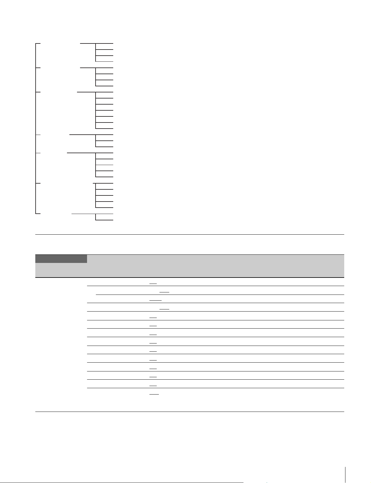
Menu Tree......................................................................25
OPERATION Menu ........................................................29
PAINT Menu...................................................................34
MAINTENANCE Menu ...................................................38
FILE Menu......................................................................42
DIAGNOSIS Menu .........................................................44
Appendix .................................................................. 45
Precautions ....................................................................45
Error Messages..............................................................45
PMW-F55 Warning and Error Messages .......................46
F65 Warning and Error Messages .................................46
Using a USB Flash Drive......................................... 47
Specifications .......................................................... 47
CA4000 ..........................................................................47
Optional Accessories/Related Equipment......................48
SKC-PB40......................................................................48
Dimensions ....................................................................49
Table of Contents
2
Page 3

Overview
The CA4000 Camera System Adaptor, in combination with a
BPU4000 Baseband Processor Unit, is a camera system
adaptor for constructing a 4K system comprising a
PMW-F55
2500 Camera Control Unit for the system camera interface.
A PMW-F55 or F65 with attached CA4000 can be connected
to a BPU4000, which performs 4K video signal processing and
down conversion to HD format, via an optical camera cable to
form a 4K camera system.
Conventional camera system operation, such as supplying
power to the camera adaptor and intercom functions, is
supported with the connection of a HDCU2000/2500 Camera
Control Unit (hereinafter referred to as the “CCU”).
It supports 4K high-frame rates, when using the F65, of 50P
(2×) and 59.94P (2×).
It also supports the PMW-F55 HD high-frame rate (HD-HFR)
imaging format to configure a system with four times or
six times
the same connection as a 4K system.
The CA4000 can also supply power to large studio lenses,
accessories, and the main supply of the F65 with the
connection of an optional SKC-PB40 Camera Power Boost
Kit.
Use the optional LA-FZB2 Mount Adaptor when using a 2/3type lens.
1) Requires PMW-F55 software version 2.10 or later.
2) An SKC-4065 F65 Adaptor (option) is required in order to mount an
F65. It also requires F65 software version 4.00 or later.
3) Supported by PMW-F55 software version 4.00 or later.
1)
or F652) as the imaging unit and an HDCU2000/
3)
the speed (optional) of a HD video system using
Knee saturation
This compensates the change of hue and decrease in chroma
that occur in highlighted areas.
This enables reproduction of natural skin tones under strong
lighting.
Low key saturation
This compensates for saturation in low-key zones. It
compensates for color reproduction in all zones, in
combination with the matrix color compensation and knee
saturation functions.
Selectable gamma table
Equipped with seven types of standard gamma tables and four
types of hyper gamma tables. Hyper gamma enables cinemalike image reproduction with wide dynamic range that cannot
be achieved with conventional video gamma.
User gamma
Gamma tables created using CvpFileEditorTM can be saved to
a “Memory Stick,” and registered in the CA4000 from an
MSU-1000/1500 or RCP-1500 series device.
Versatile detail control functions
Skin-tone detail function/Natural skin detail
function
This function controls (emphasizes or suppresses) the detail
level for specific hue or chroma areas in an image, by creating
a detail gate signal from color components of any specified
hue. The detail levels of three hues can be adjusted
independently at the same time.
The CA4000 features a natural skin detail function that adjusts
the detail gate signal in order to distinguish clearly between
parts of skin you want to smooth from the parts you do not
want to smooth, such as eyebrows.
Features
Various color-reproduction adjustment
functions
Adaptive-matrix function
This function controls the matrix calculation coefficients for
more accurate color conversion when shooting. It provides
accurate color conversion, even when shooting under
conditions that would otherwise exceed the color conversion
range of traditional matrix functions, such as under strong
monochromatic blue light sources.
Multimatrix color correction
In addition to the standard 6-axis matrix function, the unit has
a multimatrix function that permits you to adjust the hue and
chroma independently for color components in 16-axis
directions. This is helpful when color matching multiple video
cameras.
Detail boost-frequency control
The boost frequency can be adjusted, allowing the thickness
of the detail signal to be set according to the subject to achieve
high-definition image expression.
H/V ratio control
Adjusts the ratio between the applied horizontal and vertical
detail.
White/black limiter
The white and black details can be limited independently.
Focus assist functions
Supports focusing using VF detail and focus assist functions.
VF detail
Supports focusing on various scenes using a function that
adds color to the VF detail signal displayed in the viewfinder,
a function that applies modulation to flicker the VF detail
signal, and a function that changes the level of the VF detail
signal according to the zoom position.
Focus assist indicator
Displays a focusing level indicator in the viewfinder as a guide
to the focus position. This allows the focus point to be
determined easily by observing the fluctuation of the indicator.
Overview
3
Page 4

Dynamic focus
Displays a 4K resolution-specific focus point. This displays a
marker in the viewfinder, derived from the luminance signal
and color signal, for the area where 4K resolution signal is
being output (valid when shooting in 4K only).
Various viewfinder functions
Wide variety of viewfinder display options
You can display configuration settings, in addition to operation
messages, a zebra pattern, a safety-zone marker, and a
center marker in the viewfinder. Also, there are indicators
along the top and bottom of the viewfinder, such as a tally
lamp, battery warning indicator, and an indicator that warns
you when one or more settings are not within standard range.
Menu-based operation function
You can make selections and settings related to viewfinder
display items, safety zone marker, center marker, and screen
size marker, etc. quickly and easily using the menu displayed
in the viewfinder or on an external monitor.
HD prompter function
The CA4000 supports an HD prompter function where HD-SDI
equivalent digital data is sent from the HDCU2000/2500 to the
CA4000, separate from the return video signal.
Electric shock protection
This function stops the high-voltage power supply from the
camera control unit if the unit is not connected securely.
Optional accessories
Additional functionality can be added by incorporating the
following optional accessories.
For details about installing optional accessories, please
contact your Sony dealer or a Sony sales representative.
SKC-PB40 Camera Power Boost Kit
Attaches to a CA4000 to add a DC power supply output when
operating with connection to a CCU.
SKC-4065 F65 Adaptor
Interfaces between an F65 and the CA4000, allowing the
combination to be operated as an integrated system with the
F65 as the imaging unit.
Power can also be supplied to the F65 from the CCU when
used together with an SKC-PB40.
User-friendly operation
PMW-F55 design unity
The CA4000 employs a design unity with that of the
PMW-F55, following the modular design of the PMW-F55
series.
This ensures stable operation, even during shoulder
operation.
Handle slide mechanism
The handle can slide forward/backward, without requiring any
tools. This allows the operator to find the right balance when
shooting for the lens (2/3-type lens, PL mount lens, or other
diverse lenses) mounted on the camera.
The viewfinder position also slides forward/backward together
with the handle (when a PMW-F55 is mounted).
Assignable buttons
Any desired function, such as electronic color temperature
conversion, can be assigned to the assignable button on the
rear panel.
This button can be set to operate in conjunction with the
assignable switch on viewfinders, such as the HDVF-EL75
and DVF-EL100, to control the image in the viewfinder (image
magnification, for example) from the CA4000.
Also, the two buttons on the top of the handle are assignable
buttons that can be used to control lens zoom and other
functions.
USB connector
Connects to a USB flash drive for importing/exporting menu
configuration settings and other data.
Overview
4
Page 5
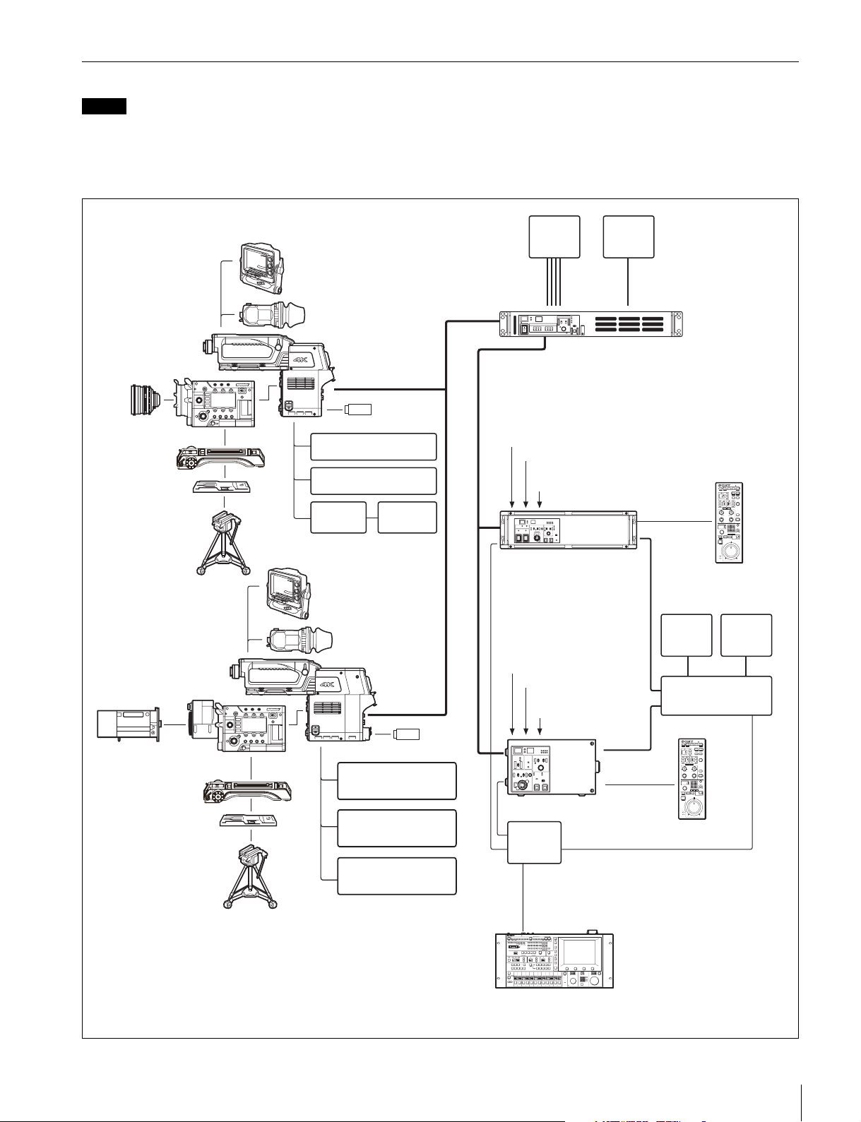
System Configuration
Note
Production of some of the peripherals and related devices shown in the figures may have been discontinued.
For advice on choosing devices, please contact your Sony dealer or a Sony sales representative.
Standard system connection example
Connection example with HDCU2000/2500 via a BPU4000 for operation as system cameras.
CA4000
Lens
PMW-F55 Solidstate Memory Camcorder
VCT-FSA5
Shoulder Adaptor
VCT-14
Tripod Adaptor
Tripod
CA4000
Lens (for studio
camera)
+SKC-PB40
a) b) c)
Viewfinder
HDVF-EL75
DVF-L700
Viewfinder
DVF-EL100
DVF-L350
Optical fiber cable
CAC-6 Return Video
Selector
Intercom Headset
CAC-12 Camera
Microphone
Holder
Viewfinder
HDVF-EL75
DVF-L700
Viewfinder
DVF-EL100
DVF-L350
USB flash
drive
Microphone
4K Video
Monitor
BNC × 4
Sync signal input
Return video input
Intercom microphone
input
Optical fiber cable
HDCU2000
Camera Control Unit
LAN cable
Sync signal input
Return video input
Intercom microphone
input
2K Video
Monitor
BNC
BPU4000
Baseband Processor Unit
CCA-5
BNC
Video
Monitor
RCP-1000 series
Remote Control Panel
Waveform
Monitor
Video Router
PMW-F55 Solid-state
Memory Camcorder (with LA-FZB2
Mount Adaptor)
VCT-FSA5
Shoulder Adaptor
VCT-14
Tripod Adaptor
Tripod
a) Use a lens supporter from the same manufacturer as the lens when
mounting a studio camera lens on a tripod.
b) Attach an SKC-PB40 Camera Power Boost Kit (option) to the unit to
supply power to studio camera lenses.
c) Use an LA-FZB2 Mount Adaptor (option) when using a 2/3-type lens.
CAC-6 Return Video
Selector
Intercom Headset
Microphone
USB flash drive
HDCU2500
Camera Control Unit
Hub
MSU-1000 series
Master Setup Unit
LAN cable
BNC
CCA-5
RCP-1000 series
Remote Control Panel
Overview
5
Page 6
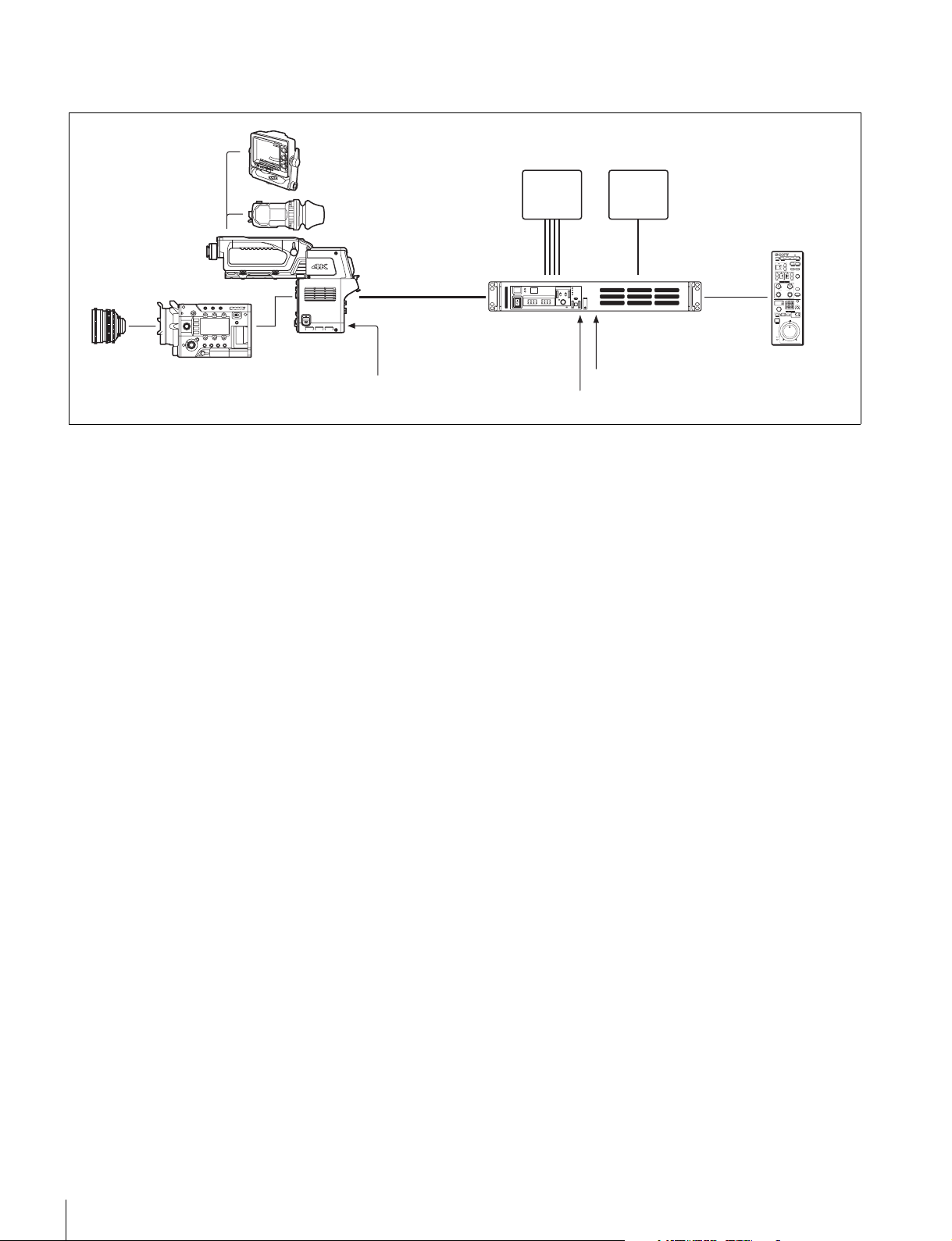
Extension mode connection example
Connection example with BPU4000 (without HDCU2000/2500) for operation as a camera extension unit.
Viewfinder
HDVF-EL75
DVF-L700
2K Video
Monitor
BNC
Sync signal input
Return video input
Lens
CA4000
PMW-F55
Solid-state Memory
Camcorder
Viewfinder
DVF-EL100
DVF-L350
Optical fiber cable
DC power supply input
4K Video
Monitor
BNC × 4
BPU4000
Baseband
Processor Unit
CCA-5
RCP-1000 series
Remote Control Panel
6
Overview
Page 7
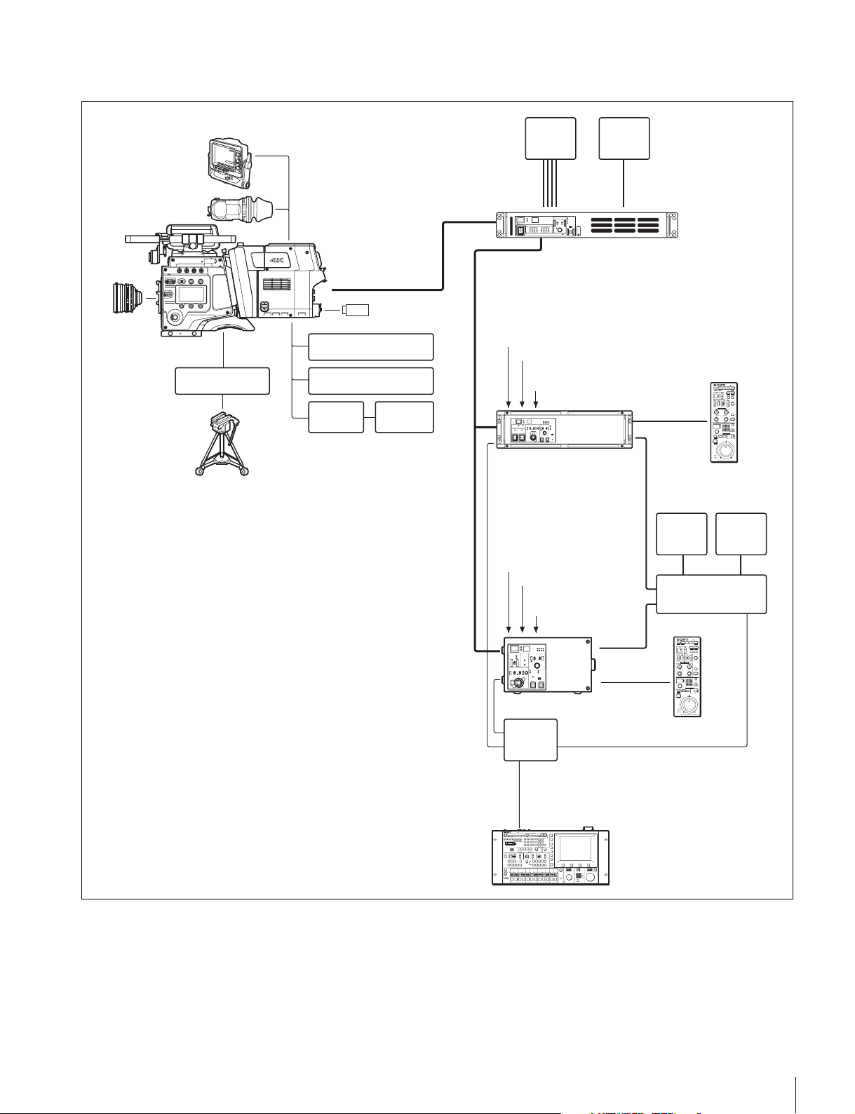
F65 connection example
Connection example with F65 for operation as a system camera.
HDVF-EL75
DVF-L700
Viewfinder
DVF-EL100
Viewfinder
Lens
F65
Digital Motion Picture
Camera
BP-8 Bridge Plate
(ARRIFLEX)
Tripod
SKC-4065+CA4000
+SKC-PB40
Optical fiber cable
USB flash drive
CAC-6 Return Video
Selector
Intercom Headset
CAC-12
Microphone
Holder
Microphone
4K Video
Monitor
BNC × 4
Sync signal input
Return video input
Intercom microphone
input
Optical fiber cable
HDCU2000
Camera Control Unit
LAN cable
Sync signal input
Return video input
Intercom microphone
input
2K Video
Monitor
BNC
BPU4000
Baseband Processor Unit
CCA-5
BNC
Video
Monitor
RCP-1000 series
Remote Control Panel
Waveform
Monitor
Video Router
HDCU2500
Camera Control Unit
Hub
MSU-1000 series
Master Setup Unit
LAN cable
BNC
CCA-5
RCP-1000 series
Remote Control Panel
Overview
7
Page 8
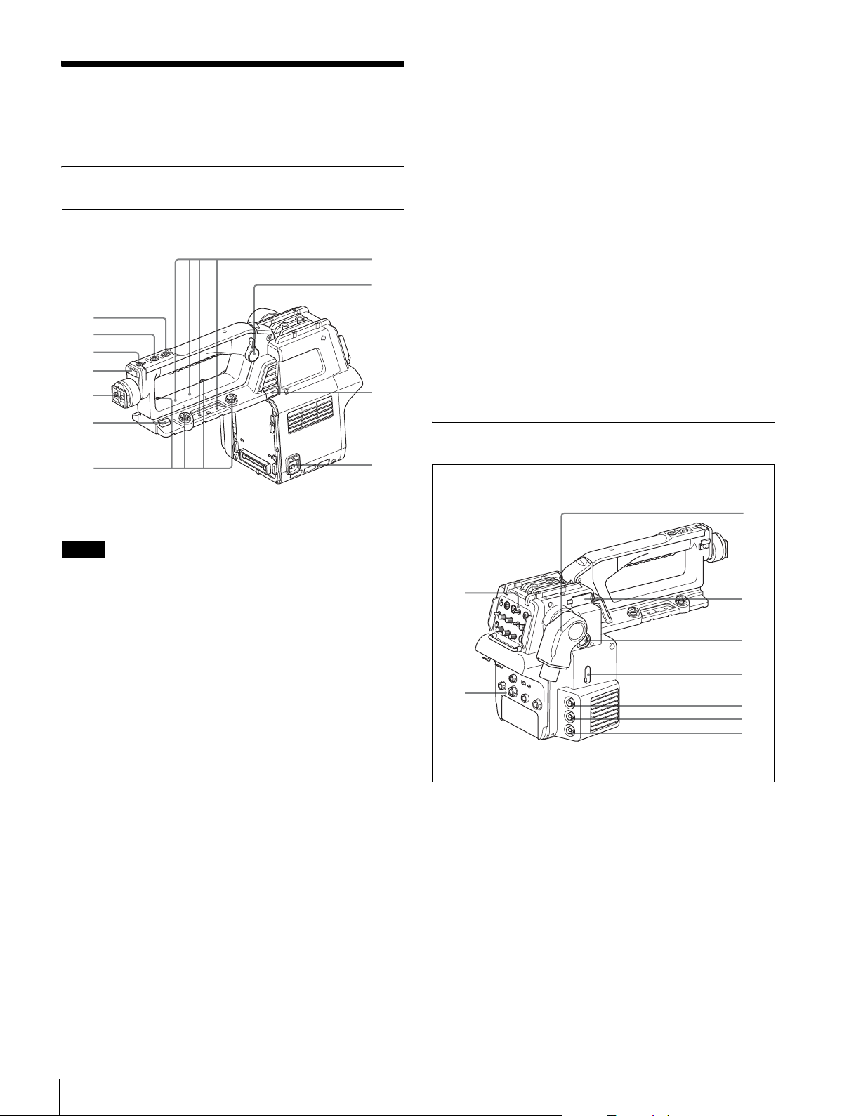
Name and Function of
8
3
f Handle slide button
Releases the handle while this button is pressed, allowing the
handle to slide when adjusting the position of the handle.
Parts
Top Panel
1
2
3
4
5
6
7
9
0
qa
g Camera mounting screws
Attaches the unit to the camera.
h Microphone holder shoe
Attaches to a microphone holder.
i Handle position lock lever
Locks the handle in position.
Turn the lever counterclockwise to release the handle to adjust
the handle position. After adjustment, turn the lever clockwise
to lock the handle in position.
j Handle flip-up lock release button
Flips up the handle while this button is pressed.
k CAMERA POWER switch
CCU: Turns on the power supply from the camera control unit.
EXT: Turns on the power supply from the DC IN connector.
Used when using the unit in extension mode.
Rear Panel
Note
In systems connected to an F65, the following handle
functions a to j cannot be used.
a INCOM (intercom) button (SY model) / ENG (engineer
line) button (CE model)
SY model: Turns the intercom microphone on while this
button is pressed.
CE model: Turns the intercom microphone on and selects the
engineer line while this button is pressed.
You can also assign other functions using the menu.
b RET 1 (return video 1) button
Monitors the return video 1 signal from the CCU in the
viewfinder while this button is pressed. It has the same
function as the RET 1 button (page 9) on the rear operation
panel.
You can also assign other functions using the menu.
c Accessory shoe
Attaches to accessories that using a 1/4 inch screw.
d Front tally
Displays a tally light, for example, in response to a tally input
on the connected camera control unit or a call signal is initiated
by pressing the CALL button.
e Viewfinder shoe
Attaches to a viewfinder.
For details about attaching, see “Attaching a Viewfinder”
(page 13).
1
2
a Operation panel (See “Operation panel”)
b Connector panel (See “Connector panel”)
c BPU (Baseband Processor Unit) connector
(optoelectrical connector)
Connects to a Baseband Processor Unit using an
optoelectrical cable.
d VF-B (viewfinder B) connector
Connects to a DVF-series viewfinder (option).
e VF-A (viewfinder A) connector
Connects to an HDVF-series viewfinder (option).
4
5
6
7
8
9
Name and Function of Parts
8
Page 9
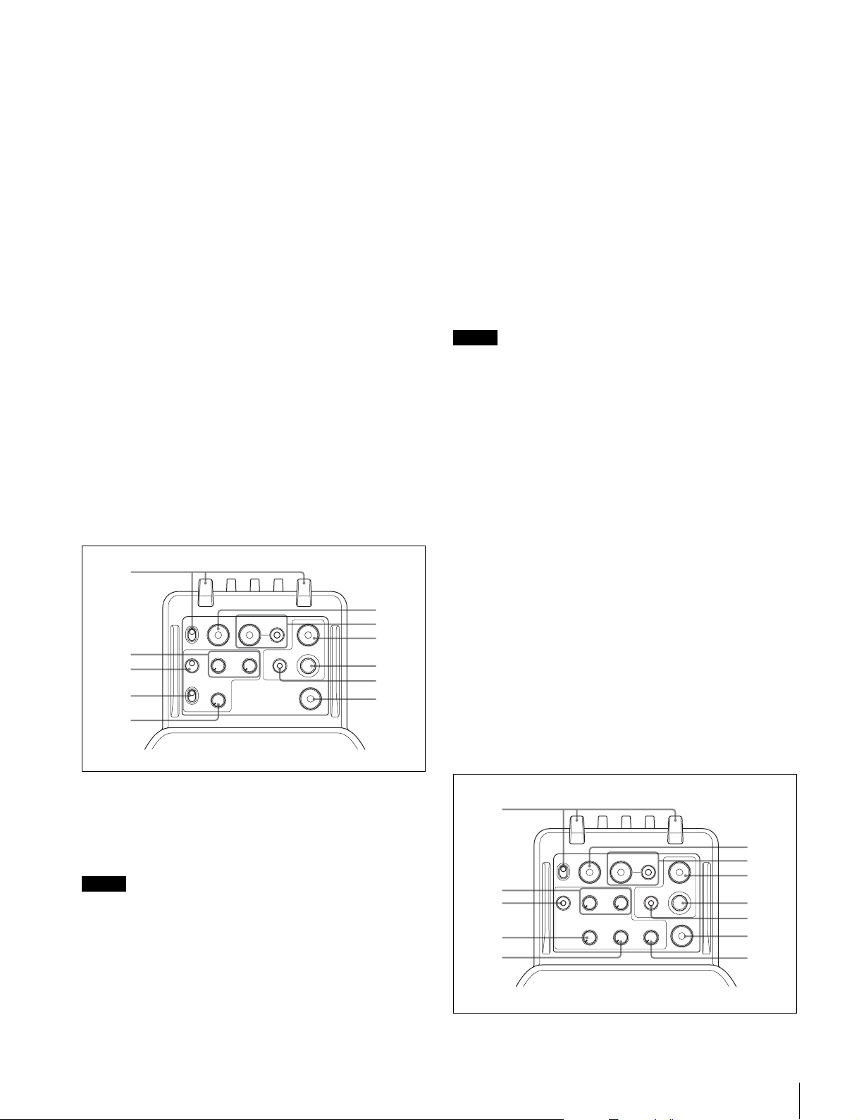
f USB connector (for USB flash drives)
1
1
Connects to a USB flash drive for saving/loading configuration
data files.
For details, see “Using a USB Flash Drive” (page 47).
g PROMPTER1 connector (BNC type)
The PROMPTER function is available when a camera control
unit is connected. Outputs prompter 1 signal (available when
connected to a camera control unit). When connected to a
camera control unit with two prompter inputs, the signal for
prompter 1 is output.
h PROMPTER2/MONITOR connector (BNC type)
Outputs prompter 2 signal.
Available only when connected to a camera control unit with a
prompter 2 input connector.
You can output a VBS signal, HD Y signal similar to the VF
connector, HD-SYNC signal, or SD-SYNC signal by selecting
the signal type in the menu.
For details about selecting the signal, see “Setting the Camera
Outputs” (page 18).
d Line selector switch
Selects the intercom line.
PROD: Producer line.
ENG: Engineer line.
e INCOM (intercom) knob
Adjusts the intercom audio volume.
f RET 1 (return video 1) button
Displays the return video 1 signal in the viewfinder while this
button is pressed.
g RET (return video) and 2/3/4 (return video 2/3/4
selector) switch
When using other return video systems in parallel with return
video 1, the return signal selected by the 2/3/4 switch is
displayed in the viewfinder while the RET button is pressed.
Note
The RET 1 button has priority over the RET (2/3/4) button if
both buttons are pressed.
i
SDI-MONI (serial digital interface) connector (BNC type)
Outputs an HD SDI signal or an HD PROMPTER signal.
For details configuring signals, see “Setting the Camera
Outputs” (page 18).
Operation panel
SY model (NTSC)
RET
2
3
4
RET1TAL LY
ON
OFF
MIC
ON
OFF
PROD
INCOM
ENG
2 3 4
DISPLAY
OFF
MENU
ASSIGNABLE
CALL
PGM2PGM1
5
a Rear tally and tally switch
ON: Displays a tally light, for example, in response to a tally
input on the connected camera control unit or when a call
signal is initiated by pressing the CALL button.
OFF: Turns the tally light off.
Note
The front tally and rear tally can be turned on/off using the
menu.
b PGM1 (program 1) and PGM2 (program 2) knobs
Adjusts the audio listening level of program 1 and program 2,
respectively.
6
7
8
9
0
qa
h ASSIGNABLE button
You can assign one of various functions to this button using
the menu displayed in the viewfinder.
i Menu control knob (rotary encoder)
Turn to select menu items and settings in the menu displayed
in the viewfinder, then press to confirm the selection.
j DISPLAY/MENU switch
Selects the screen displayed in the viewfinder.
DISPLAY: Displays text information and messages showing
the operating status, center marker, safety zone marker,
and other indicators, in addition to the camera image.
Pressing the menu control button in display mode
switches the screen to the status display.
OFF: Displays the image only.
MENU: Displays menu, in addition to the camera image.
k CALL button
Turns on the red tally light and CALL light on the RCP-1000
series Remote Control Panel or MSU-1000 series Master
Setup Unit. Used to call the RCP or MSU operator.
CE model (PAL)
6
7
8
9
0
qa
qs
2
3
4
5
RET1TAL LY
ON
OFF
MIC
LINE
PROD
OFF
ENG
ENG PROD TRACKER
RET
2 3 4
DISPLAY
OFF
MENU
ASSIGNABLE
CALL
PGM2PGM1
c MIC (microphone) switch
Switches the intercom headset microphone on/off.
Name and Function of Parts
9
Page 10
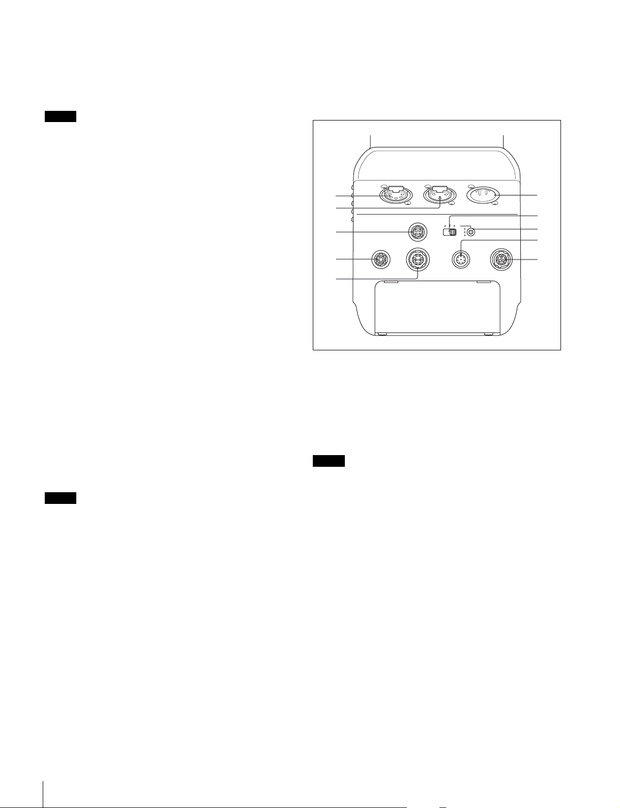
a Rear tally and tally switch
ON: Displays a tally light, for example, in response to a tally
input on the connected camera control unit or when a call
signal is initiated by pressing the CALL button.
OFF: Turns the tally light off.
Note
The front tally and rear tally can be turned on/off using the
menu.
b PGM1 (program 1) and PGM2 (program 2) knobs
Adjusts the audio listening level of program 1 and program 2,
respectively.
c MIC LINE (microphone line) switch
Switches the intercom headset microphone on/off and selects
the intercom line.
PROD: Producer line.
OFF: Headset microphone off.
ENG: Engineer line.
l CALL button
Turns on the red tally light and CALL light on the RCP-1000
series Remote Control Panel or MSU-1000 series Master
Setup Unit. Used to call the RCP or MSU operator.
Connector panel
DC INAUDIO ININTERCOM
16
2
3
4
PUSH PUSH
RET CTRL
DC OUT
TRACKER
AES/EBU
LINE MIC
+48V
OFF
REMOTE
7
8
AUX
9
0
d ENG (engineer line) knob
Adjusts the intercom audio volume of the engineer line.
e PROD (producer line) knob
Adjusts the intercom audio volume of the producer line.
f TRACKER knob
Adjusts the intercom audio volume of the line connected to the
TRACKER connector on the connector panel.
g RET 1 (return video 1) button
Displays the return video 1 signal in the viewfinder while this
button is pressed.
h RET (return video) and 2/3/4 (return video 2/3/4
selector) switch
When using other return video systems in parallel with return
video 1, the return signal selected by the 2/3/4 switch is
displayed in the viewfinder while the RET button is pressed.
Note
The RET 1 button has priority over the RET (2/3/4) button if
both buttons are pressed.
i ASSIGNABLE button
You can assign one of various functions to this button using
the menu displayed in the viewfinder.
j Menu control knob (rotary encoder)
Turn to select menu items and settings in the menu displayed
in the viewfinder, then press to confirm the selection.
k DISPLAY/MENU switch
Selects the screen displayed in the viewfinder.
DISPLAY: Displays text information and messages showing
the operating status, center marker, safety zone marker,
and other indicators, in addition to the camera image.
Pressing the menu control button in display mode
switches the screen to the status display.
OFF: Displays the image only.
MENU: Displays menu, in addition to the camera image.
5
a INTERCOM connector (XLR 5-pin)
Connects to a headset with XLR 5-pin connector for intercom
audio signal input/output.
b AUDIO IN (audio input) connector (XLR 3-pin)
Inputs an audio signal.
PMW-F55 input and CA4000 input sources are available,
selectable in the menu.
Note
When PMW-F55 input source is selected, the PMW-F55 LINE
input reference level changes from +4 dBu to 0 dBu.
c DC OUT (DC power supply output) connector (4-pin)
Supplies power to devices such as a wireless receiver (option)
(10.5 V to 17 V DC output voltage, 0.5 A (max.)).
d RET CTRL (return control) connector (6-pin)
Connects to a CAC-6 Return Video Selector.
e TRACKER connector (10-pin)
Used for an external interface, such as an intercom or tally.
f DC IN (DC power supply input) connector (XLR 4-pin)
Connects to an AC-DN10 AC Adaptor to supply power to the
unit.
g Audio input selector switch
Set to the appropriate position according to the device
connected to the AUDIO IN connector.
LINE: When a line-level (0 dBu) signal is connected
AES/EBU: When a digital audio signal is connected. (The
signal must be synchronized with the camera output.)
MIC: When a microphone is connected
Name and Function of Parts
10
Page 11
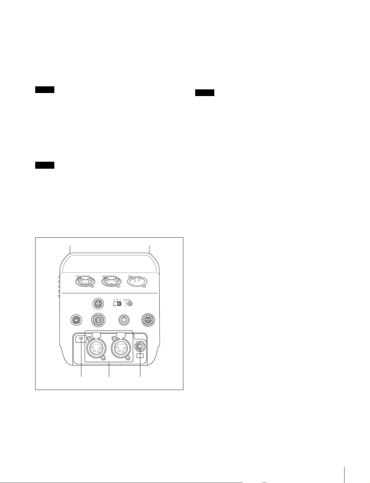
h Microphone power supply switch
12 3
Sets whether to supply power to a microphone connected to
the AUDIO IN connector.
+48V: Connects +48 V power supply to the microphone.
OFF: Does not supply power to the microphone.
(No function has been assigned to the lowermost
position. No power is supplied to the microphone when
the switch is in this position.)
b DC OUT 1/2 (DC power supply output 1/2) connectors
(XLR 4-pin)
Supplies power to optional external devices (14 V output
voltage, 6.5 A maximum current).
c DC OUT 24V (24 V DC power supply output) connector
(4-pin)
Supplies power to optional external devices (24 V output
voltage, 3.7 A maximum current).
Note
To supply +12 V power, contact a Sony sales representative
or Sony service representative.
i REMOTE connector (8-pin)
Connects to an RCP-1000/1500-series Remote Control Panel
or MSU-1000/1500 Master Setup Unit.
It is used with an RS-422A connected device under menu
control. Set the TRUNK menu on the CCU to IF: 232C/422A,
IF: 1CH for use.
Note
When the camera is connected to a camera control unit, do not
connect a remote control device or master setup unit to this
connector.
j AUX (auxiliary connection) connector (12-pin)
Connects to a lens cable. A lens cable connection enables the
unit to control lens functions.
With SKC-PB40 attached
Note
The total maximum output power for all three systems is
135 W. The maximum output power is limited by the length of
the optical camera cable, temperature, and other factors.
DC INAUDIO ININTERCOM
PUSH PUSH
RET CTRL
DC OUT
DC OUT
TRACKER
PUSH PUSH
AES/EBU
LINE MIC
+48V
OFF
REMOTE
AUX
24V
a DC OUT (DC power supply output) light
On: Indicates output from the 3-system DC OUT connector is
normal, when power is supplied from a CCU.
Flashing: Indicates that the protection circuit for one or two of
the three systems has been activated.
Off: Indicates that the protection circuit for all three systems
have been activated.
Name and Function of Parts
11
Page 12
Connection and Setup
Attaching to a Video Camera
This section describes the attachment of a PMW-F55 as an
example.
For details about attaching an F65, refer to the SKC-4065
Operation Guide.
For details about the handling of video cameras, refer to the
operating instructions supplied with the video camera.
Notes
• Requires PMW-F55 software version 2.10 or later.
• Attach to or remove from the video camera while the power
supply is turned off.
• Attach the unit to or remove it from the video camera with the
viewfinder detached. If the unit is attached or removed while
the viewfinder is still attached, the viewfinder will interfere
with the handle, causing the handle to drop and potentially
pinching your fingers.
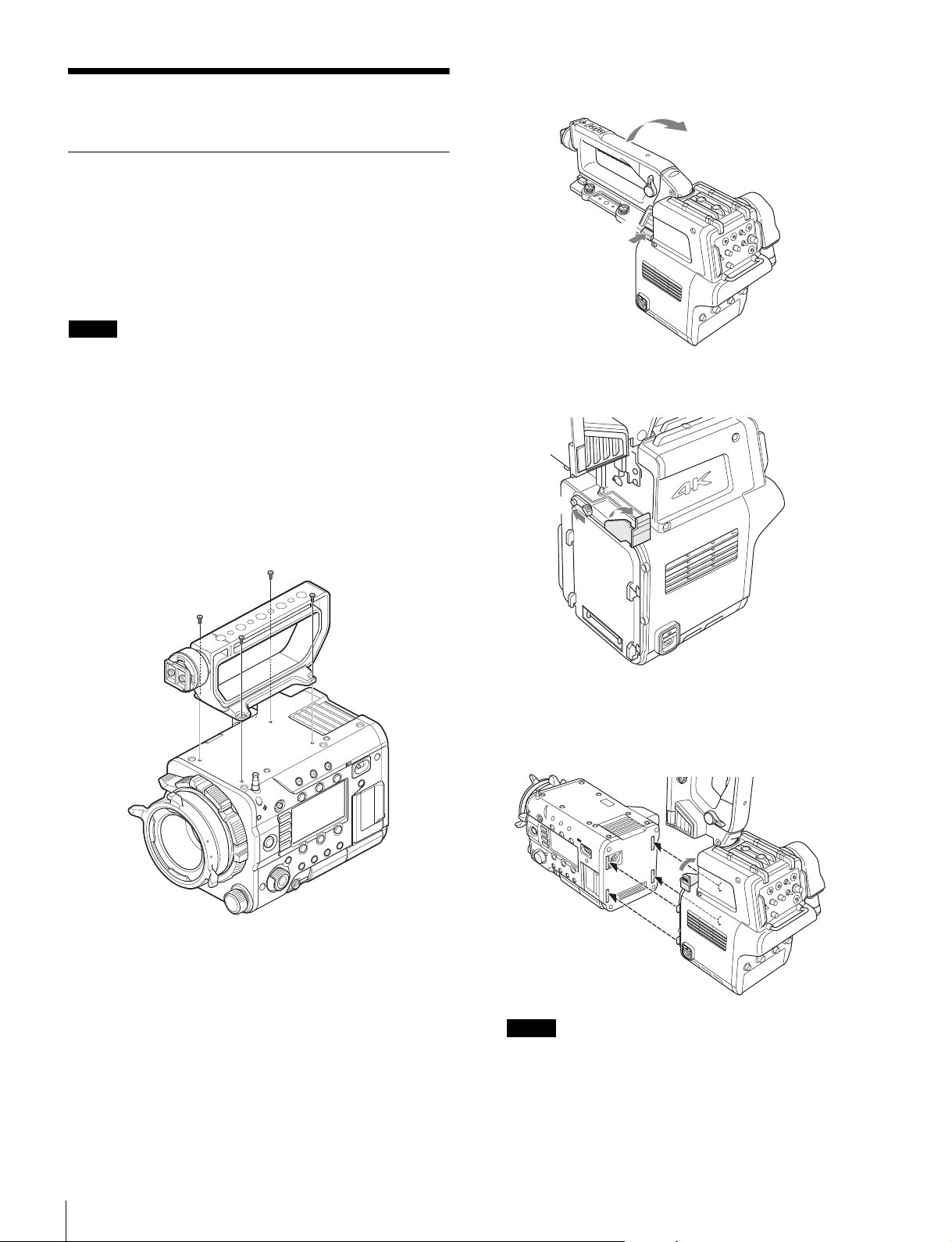
1 Remove the four screws from the top of the video
camera, and remove the handle from the video
camera body.
2 Press and hold the handle flip-up lock release button,
and raise the handle of the unit.
2
1
3 Press the release button (1) to release the catch
lever, and lift the lever all the way up (
1
2
2).
4 Insert the tabs on the unit into the grooves on the rear
panel of the video camera (
lever down (
Notes
• Check that the catch lever is pulled up before attaching
to the camera.
• Check that all four tabs are inserted correctly before
pulling the lever down. Failure to do so will result in misseating of the unit and possibly damage.
2).
1
1), then push the catch
2
Connection and Setup
12
Page 13
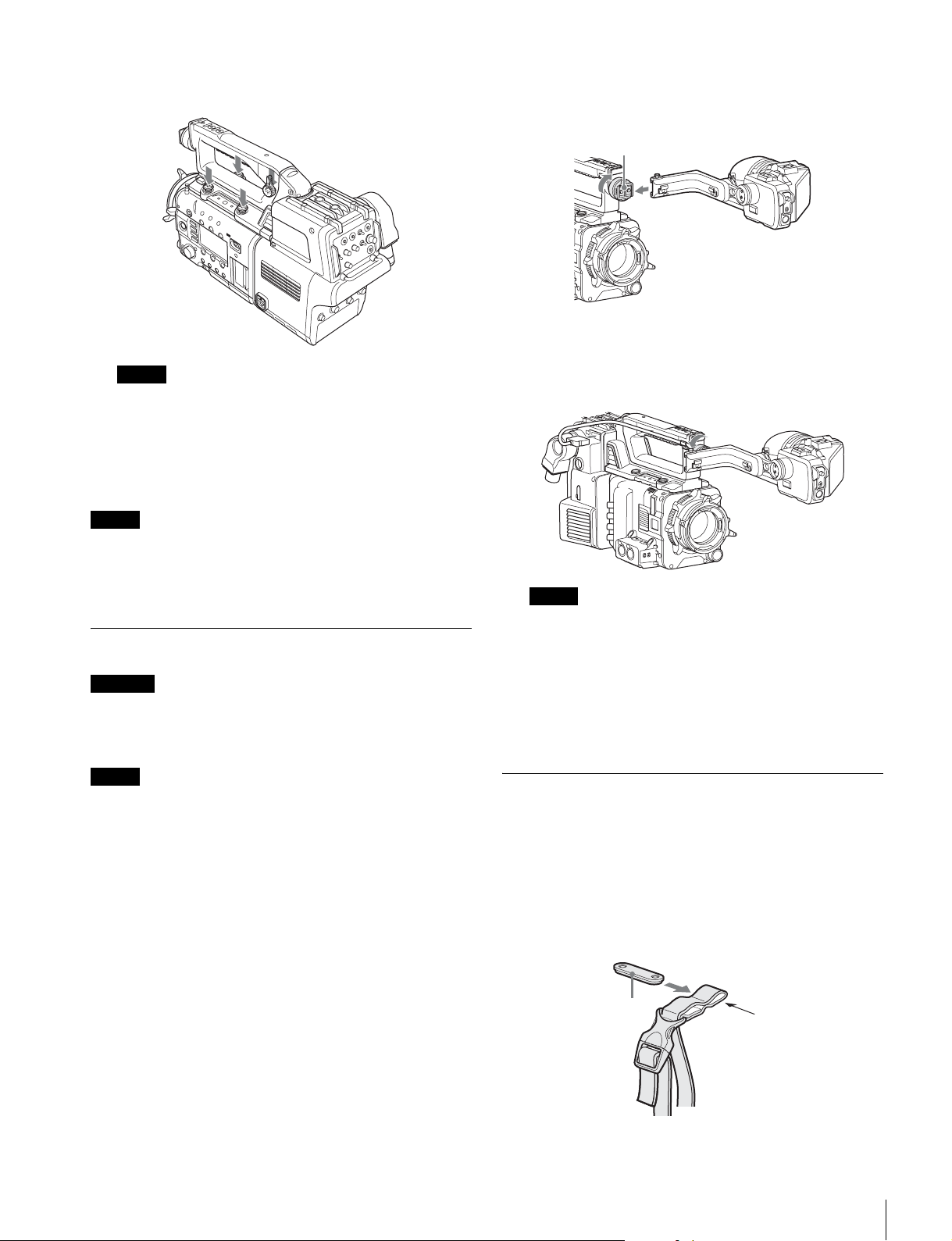
5 Lower the handle, and secure the unit to the video
camera using the camera mounting screws.
Note
Before lowering the handle, check that the catch lever is
fully pushed down. If the handle is lowered without
pushing down the catch lever, the unit may be damaged.
To remove from the video camera
Follow the attachment procedure in the reverse order.
Note
After removing the unit from a camera, check that the catch
lever is fully pushed down and then lower the handle. If the
handle is lowered without pushing down the catch lever, the
unit may be damaged.
Attaching a Viewfinder
1 Loosen the lock ring of the viewfinder shoe, align with
the slot of the viewfinder, then attach the viewfinder
by sliding it horizontally.
Viewfinder shoe
2 Tighten the lock ring after determining the left and
right position of the viewfinder, then connect the
viewfinder cable to the VF-A or VF-B connector of the
unit.
Note
Connect the viewfinder cable to the VF-A connector if
using an HDVF-series viewfinder or to the VF-B connector
if using a DVF-series viewfinder.
Caution
When the viewfinder is attached, do not leave the camera with
the eyepiece facing the sun. Direct sunlight can enter through
the eyepiece, be focused in the viewfinder and cause a fire.
Notes
• Attach/remove the viewfinder while the power supply is
turned off.
• When attaching an DVF-L700, first turn on the POWER
SWITCH of the DVF-L700 before turning on the power
supply to the unit.
For details about attaching viewfinders, refer to the operating
instructions for the viewfinder.
To remove the viewfinder
Loosen the lock ring for the viewfinder, raise the stopper, then
remove the viewfinder by sliding it in the reverse direction than
when attaching it.
Attaching the Cable Clamp Belt (Supplied)
You can secure the optoelectrical cable connected to the BPU
connector to the side of the unit by attaching the supplied
cable clamp belt.
1 Pass the belt bracket through hole A of the cable
clamp belt.
Belt bracket
A
Connection and Setup
13
Page 14
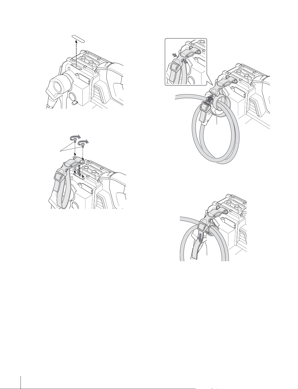
2 Peal off the seal.
Seal
4 1 Release the buckle, 2 wrap the belt around the
3 then lock the buckle again.
cable,
1
3
3 Attach the cable clamp belt to the unit using the two
supplied +B3×8 screws.
Screws (+B3×8)
2
Optoelectrical
cable
5 Adjust the length by pulling down on the end of the
belt.
Connection and Setup
14
Page 15
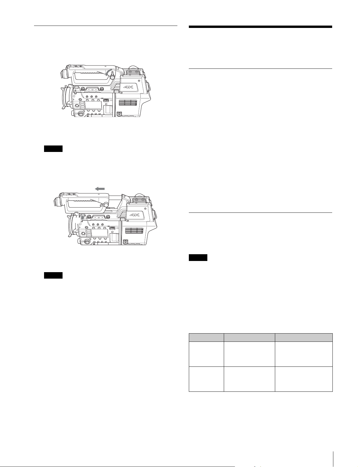
Adjusting the Handle Position
2
1 Turn the handle position lock lever counterclockwise
to release the handle.
2 Press and hold the handle slide button, and slide the
handle forward/backward.
Note
There are three positions where the handle clicks into
place, but the handle can also be locked at any other
position.
Adjustments and Settings for Shooting
Adjusting the Black Balance and White Balance
In order to maintain high picture quality, it is necessary to set
the black balance and white balance appropriately for the
conditions.
Black balance adjustment
The black balance needs adjustment in the following
circumstances:
• The first time the unit is used
• When the unit is used after a long period of disuse
• When the surrounding temperature changes significantly
• When the gain value is changed using the menu
Normally, there is no need to adjust the black balance every
time the camera is turned on.
White balance adjustment
Always readjust the white balance when lighting conditions
change.
1
3 Raise the handle position lock lever to lock the handle
in position.
Note
Always raise the handle position lock lever after adjusting
the position of the handle. If the unit is used with handle
position lock lever in the unlocked position, the handle
may slide unexpectedly and may damage other
equipment.
Setting the Electronic Shutter
This section explains the shutter modes that can be used with
the electronic shutter and gives the procedures for setting the
shutter mode and shutter speed.
Note
When a camera control unit or a remote control device is
connected, such as an MSU or RCP, control is performed from
the RCP/MSU and the switches on the video camera are
disabled.
Shutter modes
The shutter modes that can be used with the electronic shutter
of the camera and the shutter speeds that may be selected are
given below.
Supported shutter modes and speeds
Shutter mode Shutter speeds
STEP 1/100, 1/120, 1/125,
1/250, 1/500, 1/1000,
1/2000, 1/4000
seconds
ECS FREQ Variable in the range
of 60.07 Hz to 8000 Hz
* The values in the table are for a PMW-F55 shooting in 59.94P
format. The supported values vary depending on the format.
*
Usage
Use to shoot clear images
of fast-moving subjects
Use to shoot images on
video monitors without
horizontal stripe pattern
output.
Adjustments and Settings for Shooting
15
Page 16
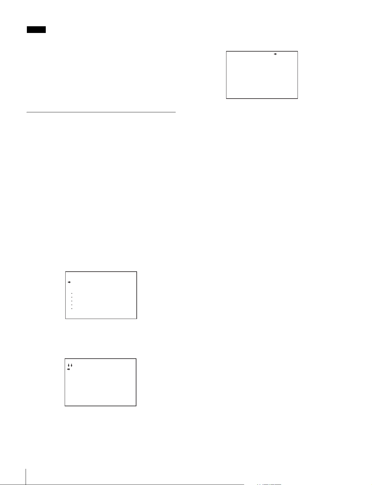
Note
With artificial lighting, particularly fluorescent lights and
mercury vapor lamps, the brightness may appear to be
constant, but in fact the intensity of the red, green, and blue
components varies in sync with the power supply frequency.
This phenomenon is known as “flicker.” When using the
electronic shutter under these lighting conditions, there are
certain cases in which the flicker is more noticeable. In
particular, color flicker is evident when the power frequency is
60 Hz. In regions where the power frequency is 50 Hz, setting
the shutter speed to 1/100 second can reduce the flicker.
Setting the Focus Assist Functions
The assist functions for easier focusing are displayed in the
viewfinder using the OPERATION menu.
Adding a VF detail signal
Adding a VF detail signal to sharp edges in the image in the
viewfinder makes it easier to judge the focus by observing
changes in the detail signal or the color of the converted detail
signal (color detail).
You adjust the focus to obtain the strongest detail signal.
1 Turn on the video camera.
2 Press and hold the menu control knob and set the
DISPLAY/MENU switch to MENU.
The camera switches to menu mode, with “TOP”
displayed in the top right corner.
5 Turn the menu control knob to move the cursor to <VF
DETAIL> and push the knob.
The <VF DETAIL> page appears.
<VF DETAIL> 04 TOP
VF DETAIL : ON 25%
CRISP : 0
FREQUENCY: 9M
FLICKER : OFF
AREA : 70%
ZOOM LINK: 100%
COLOR DETAIL : ON BLUE
PEAK COLOR : ON
CHROMA LEVEL: 100%
DYNAMIC FOCUS: OFF
6 Turn the menu control knob to move the cursor to the
item to set and push the knob.
To use the VF detail signal
Set VF DETAIL to ON to add the detail signal to sharp
edges in the image. You can adjust the signal level
(strength) in the range of 0 to 100% (default 25%).
You can adjust the characteristics of the detail signal using
the following items.
CRISP: Removes fine portions of the detail signal.
FREQUENCY: Changes the detection band of sharp
edges.
FLICKER: Turns the function to flicker the detail signal
ON/OFF (turning it ON makes it easier to check the
signal on a CRT screen).
AREA: Limits the area where the detail signal is
displayed.
ZOOM LINK: Sets the VF detail level at the WIDE position
(VF detail level changes according to the zoom
position).
3 Turn the menu control knob to move the cursor to
“TOP” and push the knob.
The TOP MENU screen appears.
<TOP MENU>
USER
USER MENU CUSTOMIZE
ALL
OPERATION
PAINT
MAINTENANCE
FILE
DIAGNOSIS
4 Turn the menu control knob to move the cursor to
OPERATION and push the knob.
The CONTENTS page of the OPERATION menu
appears.
CONTENTS 00 TOP
01.<VF DISPLAY>
02.<'!'IND>
03.<VF MARKER>
04.<VF DETAIL>
05.<DYNAMIC FOCUS>
06.<FOCUS ASSIST>
07.<ZEBRA>
08.<CURSOR>
09.<VF OUT>
10.<VF-B SETUP>
To use the color detail
Set COLOR DETAIL to ON to convert the VF detail signal
to color for display (this makes it easier to check the signal
on an LCD screen, such as the viewfinder). The display
color can be selected in the column next to “ON.”
You can adjust the color using the following items.
PEAK COLOR: Turns the function that changes the color
where the detail signal is strongest ON/OFF.
CHROMA LEVEL: Reduces the chroma components of
the video signal (applied only to the viewfinder video
signal).
DYNAMIC FOCUS: Turns the dynamic focus display on/
off (dynamic focus settings are configured on the
<DYNAMIC FOCUS> page).
7 Turn the menu control knob to display the desired
setting and push the knob.
8 When finished, set the DISPLAY/MENU switch to OFF
to exit menu mode.
Adjustments and Settings for Shooting
16
Page 17
Displaying the focus assist indicators
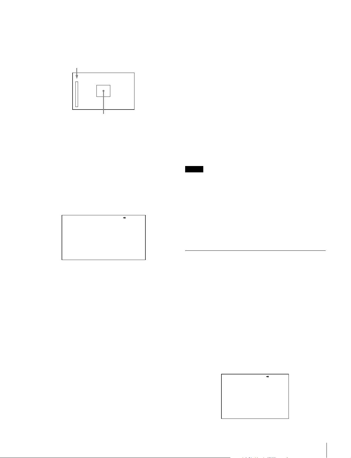
The focus assist indicator function extracts the irregularities of
a subject and converts the integral value to a level indicator for
display in the viewfinder.
Level indicator (display position and operation are adjustable)
Area marker indicating the focus detection
area (size and position are adjustable)
The focus setting where the indicator shows the maximum
level is the best focus setting. (The range of the indicator
changes significantly, depending on picture and shooting
conditions. Adjust with GAIN and OFFSET, as required.)
1 Display the CONTENTS page of the OPERATION
menu (see steps 1 to 4 in “Adding a VF detail signal”).
2 Turn the menu control knob to move the cursor to
<FOCUS ASSIST> and push the knob.
The <FOCUS ASSIST> page appears.
<FOCUS ASSIST> 06 TOP
INDICATOR : VF-A: OFF VF-B: OFF
MODE : BOX BTM
LEVEL : 70% QUICK
GAIN : 50
OFFSET : 50
AREA MARKER: VF-A: OFF VF-B: OFF
SIZE : MIDDLE
POSITION : CENTER
POSITION H: 50
POSITION V: 50
To use the area marker
Set AREA MARKER to ON to display a marker for the
focus detection area in the viewfinder.
You can set the size and position of the detection area
using the following menu items.
SIZE: Changes the size of the detection area. (If the area
size is too large, both the subject and the
background are included in the area, making the
indicator display easily deviate from the subject.)
POSITION: Coarse adjustment of the position of the
detection area.
POSITION H: Fine adjustment of the position of the
detection area in the horizontal direction.
POSITION V: Fine adjustment of the position of the
detection area in the vertical direction.
4 Turn the menu control knob to display the desired
setting and push the knob.
5 When finished, set the DISPLAY/MENU switch to OFF
to exit menu mode.
Notes
• The level indicator and the effect area marker cannot be
displayed simultaneously. Subsequently, whichever was
last set to ON is displayed.
• The area marker and the aspect safety marker cannot be
displayed simultaneously. Subsequently, whichever was
last set to ON is displayed.
• When displaying the focus assist indicators, check that the
flange back has been precisely adjusted.
For details about flange back, see the operating instructions
for the video camera.
Setting the Dynamic Focus Function
3 Turn the menu control knob to move the cursor to the
item to set and push the knob.
To use the level indicator
Set INDICATOR to ON to display the focus level indicator
in the viewfinder. You can set the display format using the
following menu items.
MODE: Sets the type and display position of the indicator.
LEVEL: Sets the strength and response speed of the
indicator.
GAIN: Adjusts the sensitivity of the indicator.
OFFSET: Adjusts the offset of the focus detection value.
1)
Normally, the sensitivity of the indicator is automatically set to
the optimum value in conjunction with the AREA MARKER
SIZE set value. Use this setting when an optimum sensitivity
value cannot be obtained, depending on the shooting
environment.
2)
Normally, the optimum offset is automatically set in conjunction
with the AREA MARKER SIZE and MASTER GAIN values.
Use this setting when the optimum offset cannot be obtained,
depending on the shooting environment.
1)
You can specify the settings for dynamic focus.
Set DYNAMIC FOCUS to “ON” on the <VF DETAIL> page
before making settings.
Dynamic focus is a function that adds marker indicators in
response to the luminance signal and color signal to the area
where 4K resolution signal is obtained (available with 4K
imaging only). It can be used to effectively display the focus
points of the 4K image.
1 Display the CONTENTS page of the OPERATION
2)
menu (see steps 1 to 4 in “Adding a VF detail signal”
(page 16)).
2 Turn the menu control knob to move the cursor to
<DYNAMIC FOCUS> and push the knob.
The <DYNAMIC FOCUS> page appears.
<DYNAMIC FOCUS> 05 TOP
DYNAMIC FOCUS: ON
FREQUENCY : EXTRA-LOW
CRISP : 6%
LEVEL : MID
PEAK COLOR : YELLOW
THRESHOLD : 50%
CHROMA LEVEL : 19%
Adjustments and Settings for Shooting
17
Page 18
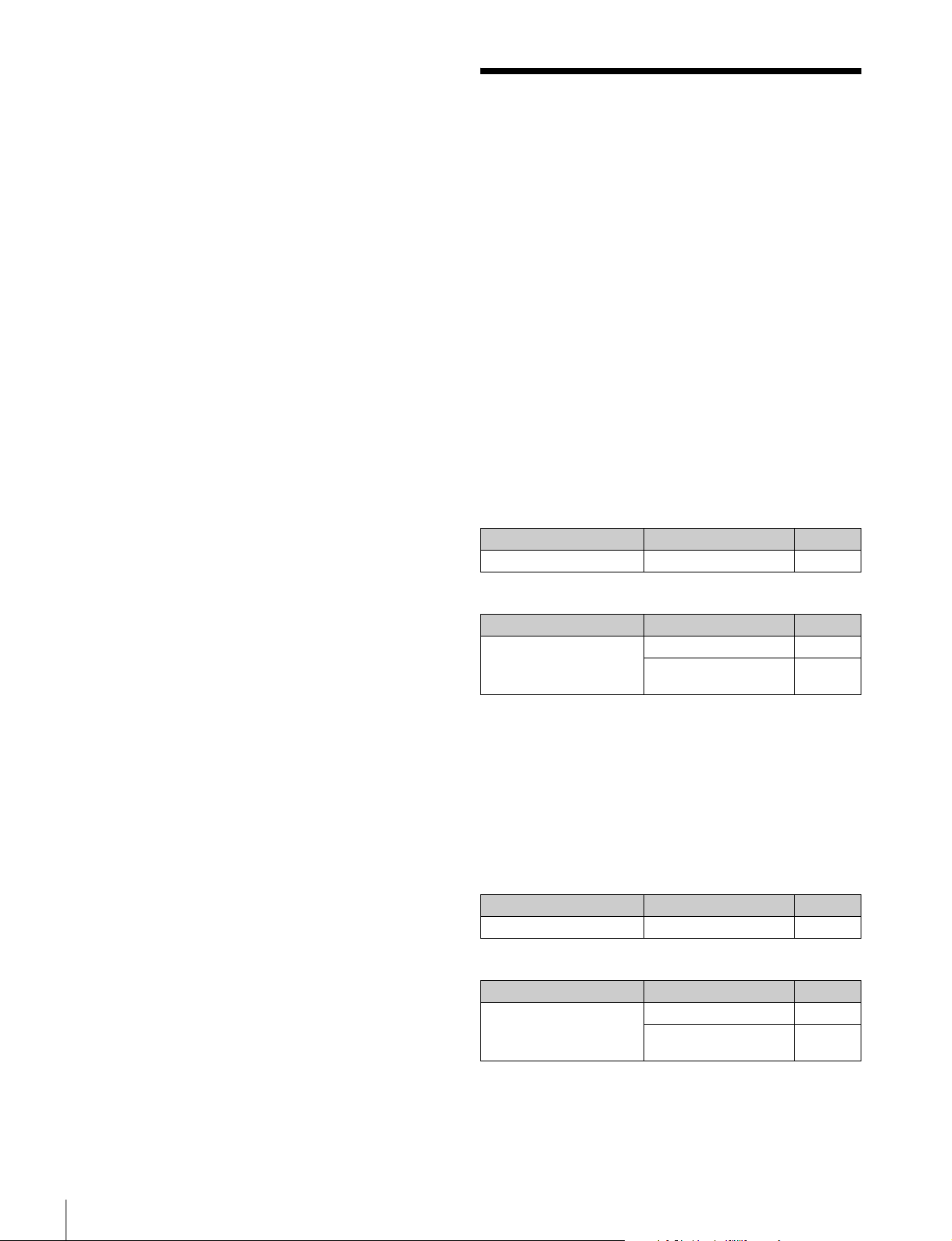
3 Turn the menu control knob to move the cursor to the
item to set and push the knob.
To use dynamic focus
When DYNAMIC FOCUS is set to “ON” on <VF DETAIL>
page, markers are displayed in response to the luminance
signal and color signal in the area where 4K resolution
video signal can be obtained.
You can set the markers using the following menu items.
FREQUENCY: Sets the detection band of the 4K
resolution high-frequency signal to one of four
options.
CRISP: Adjust to eliminate minute changes in the
detected signal.
LEVEL: Sets the luminance level of the signal for adding
markers.
PEAK COLOR: Sets the color of markers added for
regions above a fixed detection level.
THRESHOLD: Sets the peak color threshold.
CHROMA LEVEL: Sets the color depth of the peak color
display.
4 Turn the menu control knob to move the cursor to the
desired value and push the knob.
5 When finished, set the DISPLAY/MENU switch to OFF
to exit menu mode.
Setting the Camera Outputs
You can specify the video signals output from the camera
using the menu.
The menu pages used for the output settings are registered in
the USER menu by factory default.
• <PROMPTER2 OUT>
•<SDI OUT>
Set the menu items on the above menu pages to the settings
shown in the following tables.
For details about menu operations and the USER menu, see
“Menu Operations” (page 20).
Outputting the signal shot by the video camera
The same textual information as that displayed in the
viewfinder can be added to the output by setting CHARACTER
to “ON” on the <SDI OUT> or <PROMPTER2 OUT> page.
To output as HD-SDI
Menu page Item Setting
<SDI OUT> SDI-MONI OUT MAIN
To output as VBS
Menu page Item Setting
<PROMPTER2 OUT> OUTPUT VBS
DOWN CONVERTER
SELECT
MAIN
Outputting a constant return video
• When a camera control unit is connected, one of the signals
supplied to the camera control unit can be output.
• The last selected return signal is output.
• The same textual information as that displayed in the
viewfinder can be added to the output by setting
CHARACTER to “ON” on the <SDI OUT> or <PROMPTER2
OUT> page.
To output as HD-SDI
Menu page Item Setting
<SDI OUT> SDI-MONI OUT RET
To output as VBS
Menu page Item Setting
<PROMPTER2 OUT> OUTPUT VBS
DOWN CONVERTER
SELECT
RET
Setting the Camera Outputs
18
Page 19
Outputting the same image as that in the
viewfinder
In HD-SDI mode, you can obtain a signal that includes the
information (in response to the VF MARKER, CHARACTER,
VF DETAIL, ZEBRA and other settings) displayed in the
viewfinder. The individual settings (ON/OFF, etc.) are
equivalent to the settings for the viewfinder. The output is
synchronized with the switching of the Y, R, G, B, and return
signal.
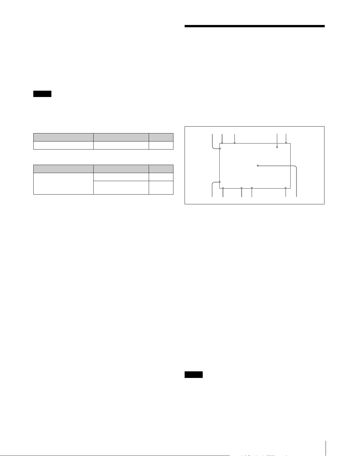
Viewfinder Screen Status Display
The viewfinder can display text information and messages
showing the operating status, center marker, safety zone
marker, and other indicators, in addition to the camera image.
Note
When the same video as the viewfinder is set for output, the
signal is output in 1080i format, even if the format setting is
720P.
To output as HD-SDI
Menu page Item Setting
<SDI OUT> SDI-MONI OUT VF-A
To output as VBS
Menu page Item Setting
<PROMPTER2 OUT> OUTPUT VBS
DOWN CONVERTER
SELECT
VF
When the DISPLAY/MENU switch is set to
DISPLAY
Items set to ON using the menu or related switches are
displayed.
1
2
3
EX Z55
TALK
5600
1A
6
7
0dB 1/125
8
9
a TALK indicator
Displayed when the intercom microphone is turned on.
b EX (lens extender) indicator
Displayed when using a lens extender.
c Zoom position indicator
Indicates the approximate position of the zoom lens variator
between wide angle (0) and telephoto (99).
45
1.0
12.5V
F5.6
0
qa
d Battery voltage indicator
When the CAMERA POWER switch is set to EXT, the DC IN
voltage is displayed. When the switch is set to CCU, the
internal voltage of the video camera is displayed.
e Focus position indicator
Displays the focus position of a display-compatible zoom lens
as a numeric value.
f 5600K mode indicator
Displayed when the internal electric filter (5600K) is set to ON.
g Filter indicator
Displays the type of filter currently selected. The number (1 to
4) indicates the ND filter, and the letter (A to D) indicates the
CC filter (only when the LA-FZB2 Mount Adaptor is attached).
Note
When an LA-FZB2 Mount Adaptor is attached, set the ND
FILTER selector switch of the PMW-F55 to CLEAR.
h Gain value indicator
Displays the video amplifier gain value (dB) set by the GAIN
switch.
Viewfinder Screen Status Display
19
Page 20
i Shutter indicator
Displays the shutter status. Nothing is displayed if the shutter
is set to OFF.
j F-stop value indicator
Displays the lens f-stop value (iris value).
k Configuration/adjustment progress message area
This area is used when the MESSAGE item in the menu is set
to other than OFF.
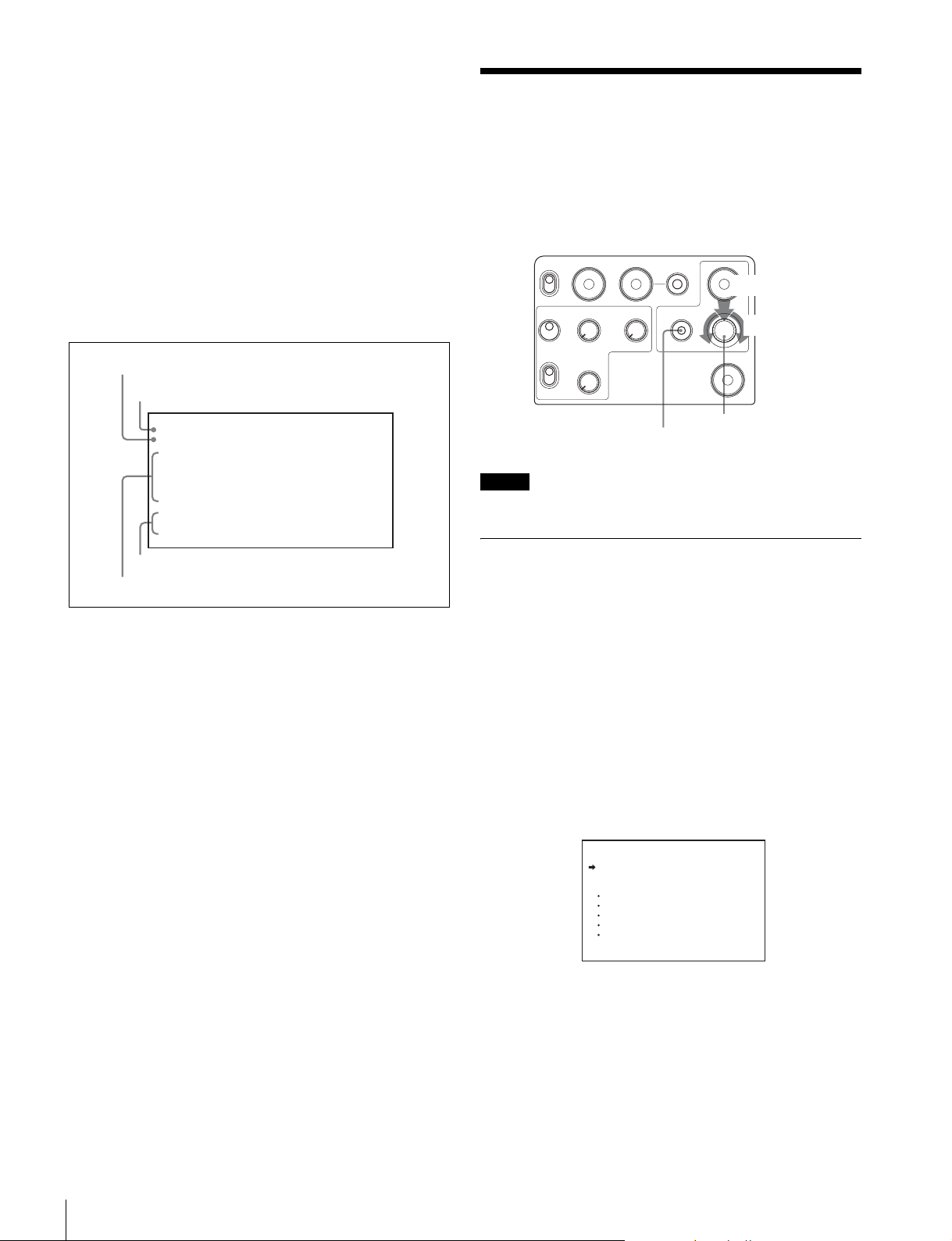
When the DISPLAY/MENU switch is set to
DISPLAY and the menu control knob is
pushed
The screen switches to the following status display.
a
d
CHU MODE :PMW-F55
ASSIGNABLE :OFF
!CC :C
OPT LV:
CAM
c
b
a Assignable switch function indicator
Displays the function assigned to the assignable switch
(page 9).
For details about functions that can be assigned, see
“<SWITCH ASSIGN1> 11 (U10)” (page 32) in the
OPERATION menu.
b ‘!’ display area
This area is used to display non-standard status, using the
<‘!’ IND> function. The display options can be set using the
menu (‘!’CC is displayed only when the LA-FZB2 Mount
Adaptor is attached).
For details, see “<‘!’ IND> 02 (U06)” (page 30) in the
OPERATION menu.
c Optical signal level indicator
Displays the light level using segments.
CAMTBPU: Optical signal level on the BPU connector of CA
unit.
CAMtBPU: Optical signal level on the CA connector of BPU
unit.
BPUTCCU: Optical signal level on the CCU connector of
BPU unit.
BPUtCCU: Optical signal level on the CAMERA connector
of CCU unit.
C
ssxxxxxxb
ssxxxxxxb
c
BPU
ssxxxxxxb
ssxxxxxxb
C
CCU
c
Menu Operations
You can make various camera settings using the menu
displayed in the viewfinder.
The following controls are used to operate the menu.
Rear operation panel
RET1TAL LY
ON
OFF
MIC
ON
OFF
PROD
INCOM
ENG
DISPLAY/MENU switch
Note
SY model shown.
Menu Display
To display a menu page
Set the DISPLAY/MENU switch to MENU.
The menu page last accessed will be displayed. If this is the
first time, the CONTENTS page of the USER menu will be
displayed.
To display the TOP MENU screen
Push and hold the menu control knob and set the DISPLAY/
MENU switch to MENU to display “TOP” in the top right corner
of the screen.
Turn the menu control knob to move the , cursor to “TOP”
and push the knob to display the TOP MENU, listing the
available menus.
RET
2 3 4
PGM2PGM1
<TOP MENU>
USER
USER MENU CUSTOMIZE
ALL
OPERATION
PAINT
MAINTENANCE
FILE
DIAGNOSIS
ASSIGNABLE
DISPLAY
OFF
MENU
Menu control knob
Push
Turn
CALL
d CHU MODE indicator
Displays the current connection status (CHU MODE setting)
(page 41).
Menu Operations
20
Page 21
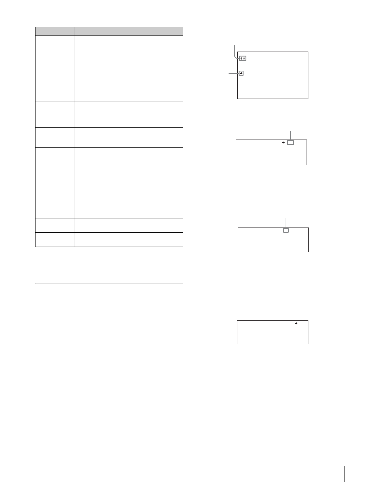
Menu Description
USER This menu includes often-used menu pages
USER MENU
CUSTOMIZE
ALL This menu permits you to control all items of the
OPERATION This menu contains items for video camera
PAINT This menu contains items for making detailed
MAINTENANCE This menu contains items for performing camera
FILE This menu is for performing file operations, such
DIAGNOSIS This menu is used to display self-diagnostic
selected from among the OPERATION, PAINT,
MAINTENANCE, FILE, and DIAGNOSIS menus.
You can edit the factory default menu structure
(page 22) using the USER MENU CUSTOMIZE
menu.
This menu allows you to edit the USER menu
items.
For details, see “Editing the USER Menu”
(page 22).
OPERATION menu, PAINT menu,
MAINTENANCE menu, FILE menu, and
DIAGNOSIS menu as a single menu.
operators to operate the camera. It mainly
permits viewfinder, intercom, and switch settings.
image adjustments while using a waveform
monitor to monitor the waveforms output from the
video camera. Support of a video engineer is
usually required to use this menu.
Although you can also use an external control
device (RCP/RM, etc.)to set the items on this
menu, the menu is useful when using the camera
by itself outdoors.
maintenance and infrequently used “paint” items.
as writing or clearing the reference file.
information.
To disable the “TOP” indication
Turn the power off and then on again to disable selection of
TOP.
Menu Settings
To select a menu from TOP MENU
Turn the menu control knob to move the , cursor to the
desired menu and push the knob.
The CONTENTS page (page No. 00) or the last accessed
page of the selected menu is displayed.
To select a page from the menu CONTENTS
page
Turn the menu control knob to move the , cursor to the
desired page and push the knob.
Arrows are displayed to indicate the direction for
scrolling if the page is scrollable.
CONTENTS 00 TOP
01.<VF DISPLAY>
02.<'!'IND>
Cursor
03.<VF MARKER>
04.<VF DETAIL>
05.<DYNAMIC FOCUS>
06.<FOCUS ASSIST>
07.<ZEBRA>
08.<CURSOR>
09.<VF OUT>
10.<VF-B SETUP>
The selected page appears.
Page No.
<VF DETAIL> 04 TOP
VF DETAIL : ON 25%
CRISP : 0
FREQUENCY: 9M
FLICKER : OFF
To change the displayed page
1 Check that the , cursor is pointing to the page
number then push the menu control knob.
The , cursor changes to a flashing ? (question mark).
Flashing
<VF DETAIL> ? 04 TOP
VF DETAIL : ON 25%
CRISP : 0
FREQUENCY: 9M
FLICKER : OFF
2 Turn the menu control knob to flip through the pages,
and push the knob when the desired page is
displayed.
The ? (question mark) changes back to ,. Items on the
page can now be selected.
To return to the TOP MENU screen
Turn the menu control knob to move the , cursor to TOP
and push the knob.
<VF DETAIL> 04 TOP
VF DETAIL : ON 25%
CRISP : 0
FREQUENCY: 9M
FLICKER : OFF
To set a menu item
If ? (question mark) is displayed to the left of the page number,
push the menu control knob to change to the , cursor.
Settings on the displayed page can now be modified.
1 Turn the menu control knob to move the , cursor to
the desired item to set and push the knob.
The , cursor changes to a flashing ? (question mark).
2 Turn the menu control knob to change the setting.
When the knob is turned quickly, the values change
quickly for coarse adjustment; when turned slowly, the
values change slowly for fine adjustment.
Menu Operations
21
Page 22
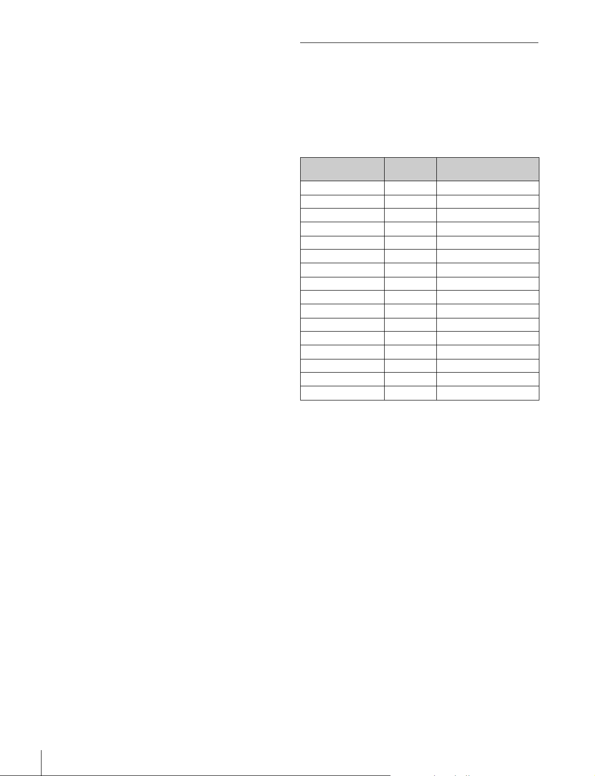
To cancel a changed setting
Set the STATUS/CANCEL switch to CANCEL before
pushing the menu control knob to restore the original
setting.
To suspend menu changes
Set the DISPLAY/MENU switch to OFF to turn off the
menu screen display.
The menu setting operation can be restarted by setting
the DISPLAY/MENU switch back to MENU.
3 Push the menu control knob.
The ? (question mark) changes back to ,, and the item
setting is registered.
4 To change other settings on the same menu page,
repeat steps 1 to 3.
To enter a character string
If you press the menu control knob when the , cursor is
pointing to a text item, such as a file ID, a square cursor and
the list of selectable characters are displayed.
The cursor is moved by turning the menu control knob.
1 Move the cursor to the position where you wish enter
a character and push the menu control knob.
The cursor is displayed in the character list.
2 Move the cursor to the character to enter and push
the menu control knob.
Repeat steps 1 and 2 to enter other characters.
• Select INS to insert a space character at the cursor
position.
• Select DEL to delete the character at the cursor
position.
• Select RET to return to step 1 without changing the
character.
• Entering the maximum number of characters (up to the
right edge) moves the cursor to ESC on the lower right
of the character list.
Editing the USER Menu
You can select desired pages and items from the
OPERATION, PAINT, MAINTENANCE, FILE, and
DIAGNOSIS menus and register them in the USER menu.
Registering frequently-used pages and items in the USER
menu is useful for quickly and simply changing settings.
The following pages are included in the USER menu by factory
default.
Menu page USER
menu No.
<VF OUT> U01 OPERATION 09
<VF DETAIL> U02 OPERATION 04
<DYNAMIC FOCUS> U03 OPERATION 05
<FOCUS ASSIST> U04 OPERATION 06
<VF DISPLAY> U05 OPERATION 01
<‘!’ IND> U06 OPERATION 02
<VF MARKER> U07 OPERATION 03
<CURSOR> U08 OPERATION 08
<ZEBRA> U09 OPERATION 07
<SWITCH ASSIGN1> U10 OPERATION 11
<SWITCH ASSIGN2> U11 OPERATION 12
<HEADSET MIC> U12 OPERATION 14
<OUTPUT FORMAT> U13 MAINTENANCE M08
<PROMPTER2 OUT> U14 MAINTENANCE M09
<SDI OUT> U15 MAINTENANCE M10
<ROM VERSION> U16 DIAGNOSIS D03
For details about the items on each page, see the source
menu tables in “Menu List” (page 25).
The USER MENU CUSTOMIZE menu allows you to add,
delete, and reorder pages and items in the USER menu to
make it easier to use.
Source menu / Page No.
3 Select END and push the menu control knob.
The new input string is registered.
To restore the original character string
Select ESC and push the menu control knob.
To restore a setting to its standard value
Select the menu item and push and hold the menu control
knob for 3 seconds when the , cursor is displayed to restore
the setting to the reference file value.
If 10 SEC CLEAR has been set to ON on the <FILE CLEAR>
page of the FILE menu, you can reset the setting in the
reference file for the selected item to the factory-set value by
pushing and holding the menu control knob for a further
10 seconds.
To exit the menu
Set the DISPLAY/MENU switch to OFF.
Menu Operations
22
Editing by item
The USER MENU CUSTOMIZE menu allows you to add a
new page to the USER menu and add desired items to the
page.
When shipped, the EDIT page contains factory-preset items,
but USER 1 EDIT to USER 19 EDIT pages are all blank. You
can register up to 10 items, including blank lines, on each of
these pages.
Page 23

To add items to a page
5 Add the items.
1 Select USER MENU CUSTOMIZE on the TOP MENU
screen (see page 20).
If this is the first time the USER MENU CUSTOMIZE
menu has been displayed, the CONTENTS page appears.
CONTENTS E00
xx
01.EDIT PAGE
02.USER 1 EDIT
c
03.USER 2 EDIT
04.USER 3 EDIT
05.USER 4 EDIT
06.USER 5 EDIT
07.USER 6 EDIT
08.USER 7 EDIT
09.USER 8 EDIT
10.USER 9 EDIT
TOP
If the menu has been used before, the page last accessed
appears.
2 If the CONTENTS page is displayed, turn the menu
control knob until the , cursor points to one of
USER 1 EDIT to USER 19 EDIT, then push the knob to
select the page.
If a different page is displayed, turn the menu control
knob until the desired page screen appears then push
the knob to select the page.
Example: When you select the USER 2 EDIT page
USER 2 EDIT E03cTOP
1 Turn the menu control knob until the page that has the
desired items appears, then push the knob.
2 Turn the menu control knob to move the , cursor to
the desired item and push the knob.
The USER 2 EDIT page appears again, displaying the
added item.
6 Repeat steps 3 to 5 to add the remaining items.
You can add up to 10 items per page.
To change the order of items on a page
1 Move the , cursor to the item to be moved and push
the menu control knob.
The EDIT FUNCTION screen appears.
2 Select MOVE and push the menu control knob.
The previously displayed page appears again.
3 Move the , cursor to the position where you wish to
move the page and push the menu control knob.
ITEM MOVE
xx
c
VF OUT : COLOR
VF DETAIL : OFF
MARKER : ON
CURSOR : OFF
ZEBRA SW : OFF
: 1
z
ASSIGNABLE1 : OFF
ESC
3 Move the , cursor to the item to be added (this
operation is unnecessary if no item exists on the
page, as shown in the figure above) then push the
menu control knob.
The EDIT FUNCTION screen appears.
EDIT FUNCTION
c
INSERT
MOVE
DELETE
BLANK
ESC
4 Move the , cursor to INSERT and push the menu
control knob.
The page with the last item added appears.
<SW STATUS> P01
FLARE :
GAMMA : ON
BLK GAM : OFF
KNEE : ON
WHT CLIP: ON
DETAIL : ON
LVL DEP : ON
SKIN DTL: OFF
MATRIX : OFF
c
ON
ESC
The item selected in step 1 moves to the position that you
selected in step 3.
In the above example, ASSIGNABLE1 is moved to the top,
and the other items are moved down one line.
To delete an item from a page
1 Move the , cursor to the item to be deleted and push
the menu control knob.
The EDIT FUNCTION screen appears.
2 Select DELETE then push the menu control knob.
The previously displayed page appears again, and the
message “DELETE OK? YES,NO” appears.
3 Move the , cursor to YES and push the menu control
knob.
To insert a blank line
1 Move the , cursor to the item above which you wish
to insert a blank line and push the menu control knob.
The EDIT FUNCTION screen appears.
2 Select BLANK then push the menu control knob.
The previously displayed page appears again, and a blank
line is inserted above the specified item.
Menu Operations
23
Page 24

Note
You cannot insert a blank line on a page if 10 items have
already been registered.
Editing by page
You can add a page to the USER menu, delete a page from
the USER menu, or replace pages, using the EDIT PAGE of
the USER MENU CUSTOMIZE menu.
To add a page
1 Select USER MENU CUSTOMIZE on the TOP MENU
screen.
If this is the first time the USER MENU CUSTOMIZE
menu has been displayed, the CONTENTS page appears.
If the menu has been used before, the page last accessed
appears.
To delete a page
1 On the EDIT PAGE screen of the USER MENU
CUSTOMIZE menu, move the , cursor to the page to
be deleted and push the menu control knob.
The EDIT FUNCTION screen appears.
2 Select DELETE then push the menu control knob.
The previously displayed page appears again, and the
message “DELETE OK? YES,NO” appears.
ITEM DELETE
DELETE OK? YES
01.<VF OUT>
02.<VF DETAIL>
03.<DYNAMIC FOCUS>
04.<FOCUS ASSIST>
z
05.<VF DISPLAY>
06.<'!' IND>
07.<VF MARKER>
08.<CURSOR>
09.<ZEBRA>
10.<SWITCH ASSIGN1>
ESC
c
NO
2 If the CONTENTS page is displayed, turn the menu
control knob to move the , cursor to EDIT PAGE and
push the menu control knob to display the EDIT PAGE
screen.
If a different page is displayed, turn the menu control
knob until the EDIT PAGE screen appears and push
the menu control knob to select the page.
EDIT PAGE E01
xx
01.<VF OUT>
c
02.<VF DETAIL>
03.<DYNAMIC FOCUS>
04.<FOCUS ASSIST>
05.<VF DISPLAY>
06.<'!' IND>
07.<VF MARKER>
08.<CURSOR>
09.<ZEBRA>
10.<SWITCH ASSIGN1>
TOP
3 Move the , cursor to the position where you wish to
add the page and push the menu control knob.
The EDIT FUNCTION screen appears.
4 Select INSERT then push the menu control knob.
The selected page appears.
CONTENTS
xx
c
01.USER 1
02.USER 2
03.USER 3
04.USER 4
05.USER 5
06.USER 6
07.USER 7
08.USER 8
09.USER 9
10.USER 10
ESC
3 Move the , cursor to YES and push the menu control
knob.
To change the order of pages
1 On the EDIT PAGE screen of the USER MENU
CUSTOMIZE menu, move the , cursor to the page
that you wish to move and press the menu control
knob.
The EDIT FUNCTION screen appears.
2 Select MOVE and push the menu control knob.
The EDIT PAGE screen appears again.
3 Move the , cursor to the position where you wish to
move the page and push the menu control knob.
ITEM MOVE
xx
01.<VF OUT>
02.<VF DETAIL>
03.<DYNAMIC FOCUS>
04.<FOCUS ASSIST>
c
05.<VF DISPLAY>
06.<'!' IND>
07.<VF MARKER>
08.<CURSOR>
09.<ZEBRA>
z
10.<SWITCH ASSIGN1>
The page selected in step 1 moves to the position selected in
step 3. In the above example, <SWITCH ASSIGN1> moves to
05, and the <VF DISPLAY> and following pages move down
one line.
ESC
5 Move the , cursor to the desired page and push the
menu control knob.
This adds the page above the item position selected in
step 3.
To cancel addition of a page
Before pushing the menu control knob in step 5, turn the
menu control knob to move the , cursor to ESC at the
top right of the screen and push the knob.
The EDIT PAGE screen appears again.
Menu Operations
24
Page 25
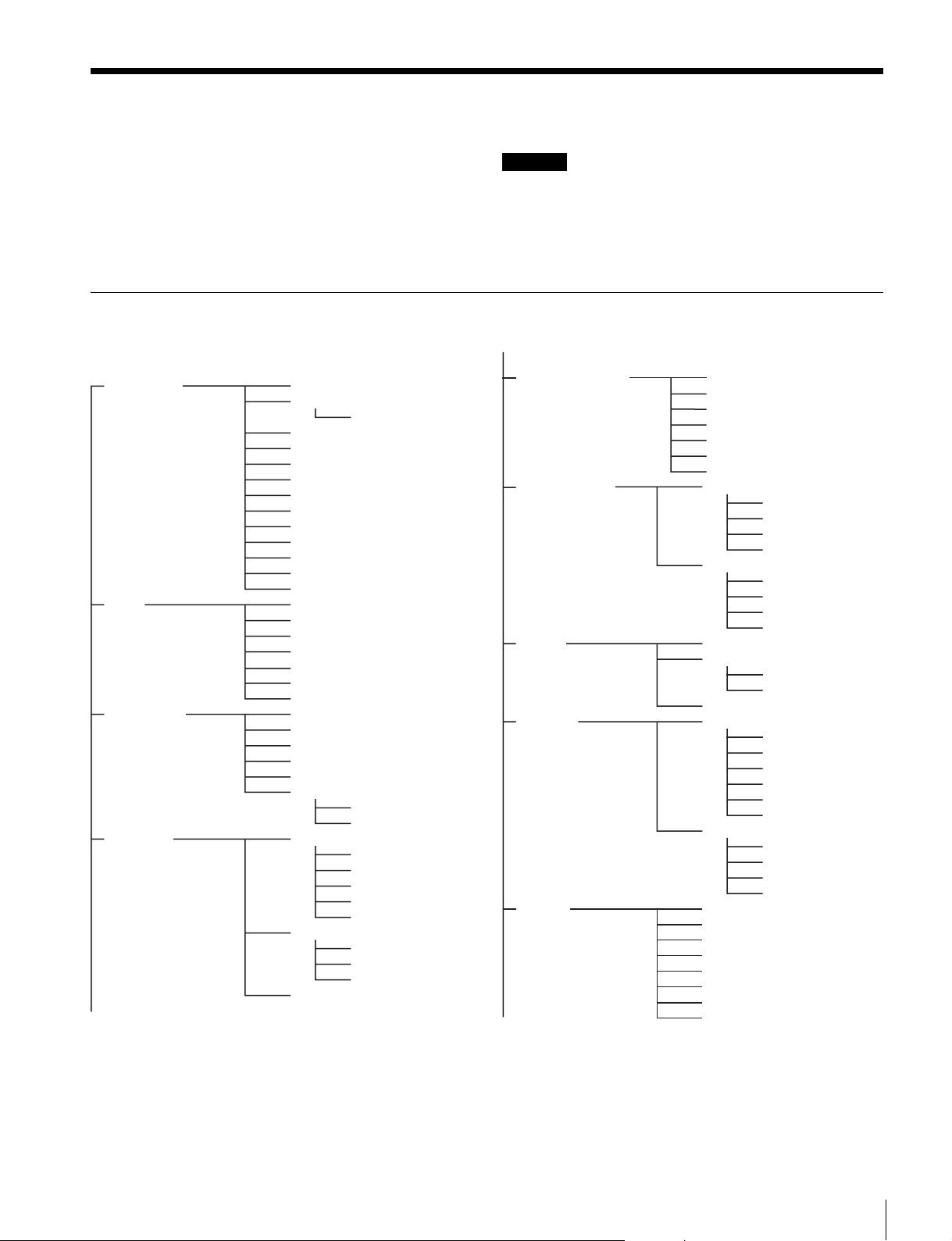
Menu List
This section shows the menus displayed in the viewfinder in
tables.
• For pages that have been registered in the USER menu at
the factory, the USER menu page numbers are indicated in
parenthesis in the No. column of the tables.
• A CONTENTS page (numbered 00) is also provided for
each menu.
Menu Tree
OPERATION menu
VF DISPLAY
01 (U05)
'!' IND
02 (U06)
VF MARKER
03 (U07)
VF DETAIL
04 (U02)
EX
ZOOM
DISP
FOCUS
ND
CC
5600K
IRIS
GAIN
SHUTTER
RETURN
TALK
MESSAFAGE
ND
CC
5600K
SHUTTER
FAN
EXT
Y TALLY
MARKER
LEVEL
CENTER
SAFETY ZONE
EFFECT
ASPECT
MASK
SAFETY
VF DETAIL
CRISP
FREQUENCY
FLICKER
AREA
COLOR DETAIL
PEAK COLOR
CHROMA LEVEL
DYNAMIC FOCUS
ZOOM LINK
COLOR SEL
Legend
CCU: HDCU2000 or HDCU2500 Camera Control Unit
Settings: Factory default settings shown underlined.
ENTER to execute: Execute by pushing the menu control knob.
DYNAMIC FOCUS
05 (U03)
FOCUS ASSIST
06 (U04)
ZEBRA
07 (U09)
CURSOR
08 (U08)
VF OUT
09 (U01)
DYNAMIC FOCUS
FREQUENCY
CRISP
LEVEL
PEAK COLOR
THRESHOLD
CHROMA LEVEL
INDICATOR
MODE
LEVEL
GAIN
OFFSET
AREA MARKER
SIZE
POSITION
POSITION H
POSITION V
ZEBRA
ZEBRA1
LEVEL
WIDTH
ZEBRA2
CURSOR
LEVEL
BOX/CROSS
H POSITION
V POSITION
WIDTH
HEIGHT
BOX MEMORY
H POSI
V POSI
WIDTH
HEIGHT
VF-A OUT
VF-B OUT
RET MIX VF
MIX DIRECTION
MIX VF MODE
MIX VF LEVEL
CHARACTER LEVEL
SHRINK MODE
Menu List
25
Page 26

VF-B SETUPT RESOLUTION
10
SWITCH ASSIGN1
11 (U10)
SWITCH ASSIGN2
12 (U11)
RETURN
13
HEADSET MIC
14 (U12)
INTERCOM
15
TRACKER
16
OPERATOR FILE
17
CONTRAST
BRIGHTNESS
PEAKING
ASSIGNABLE
LENS VTR S/S
HANDLE SW1
HANDLE SW2
ZOOM SPEED
RET1 SEL
RET2 SEL
RET1+ RET2
VBS RET ASPECT
INTERCOM MIC
LEVEL
POWER
UNBAL
INTERCOM RECEIVE SELECT
INTERCOM
(SY model)
ENG (CE model)
PROD (CE model)
PGM1
PGM2
TRACKER
SIDE TONE
TRACKER RECEIVE SELECT
INTERCOM
(SY model)
ENG (CE model)
PROD (CE model)
PGM1
PGM2
INPUT LEVEL
OUTPUT LEVEL L-CH
OUTPUT LEVEL R-CH
READ (USB t CAM)
WRITE (CAM t USB)
PRESET
FILE ID
CAM CODE
DATE
PAINT menu
SW STATUS
P01
VIDEO LEVEL
P02
COLOR TEMP
P03
GAMMA
P04
BLACK GAMMA
P05
SATURATION
P06
KNEE
P07
WHITE CLIP
P08
DETAIL 1
P09
DETAIL 2
P10
FLARE
GAMMA
BLK GAM
KNEE
WHT CLIP
DETAIL
LVL DEP
SKIN DTL
MATRIX
WHITE
BLACK
FLARE
GAMMA
FLARE
TEST
WHITE
AUTO WHITE
BALANCE
COLOR TEMP
BALANCE
MASTER
LEVEL
COARSE
TABLE
GAMMA
TEST
LEVEL
RANGE
TEST
SATURATION
LOW KEY SAT
RANGE
TEST
K POINT
K SLOPE
KNEE
KNEE MAX
KNEE SAT
AUTO KNEE
POINT LIMIT
SLOPE
ABS
W CLIP
ABS
DETAIL
LEVEL
LIMITER M
LIMITER WHT
LIMITER BLK
CRISP
LEVEL DEPEND
ABS
H/V RATIO
FREQ
MIX RATIO
KNEE APT
DTL H/V MODE
ABS
26
Menu List
Page 27
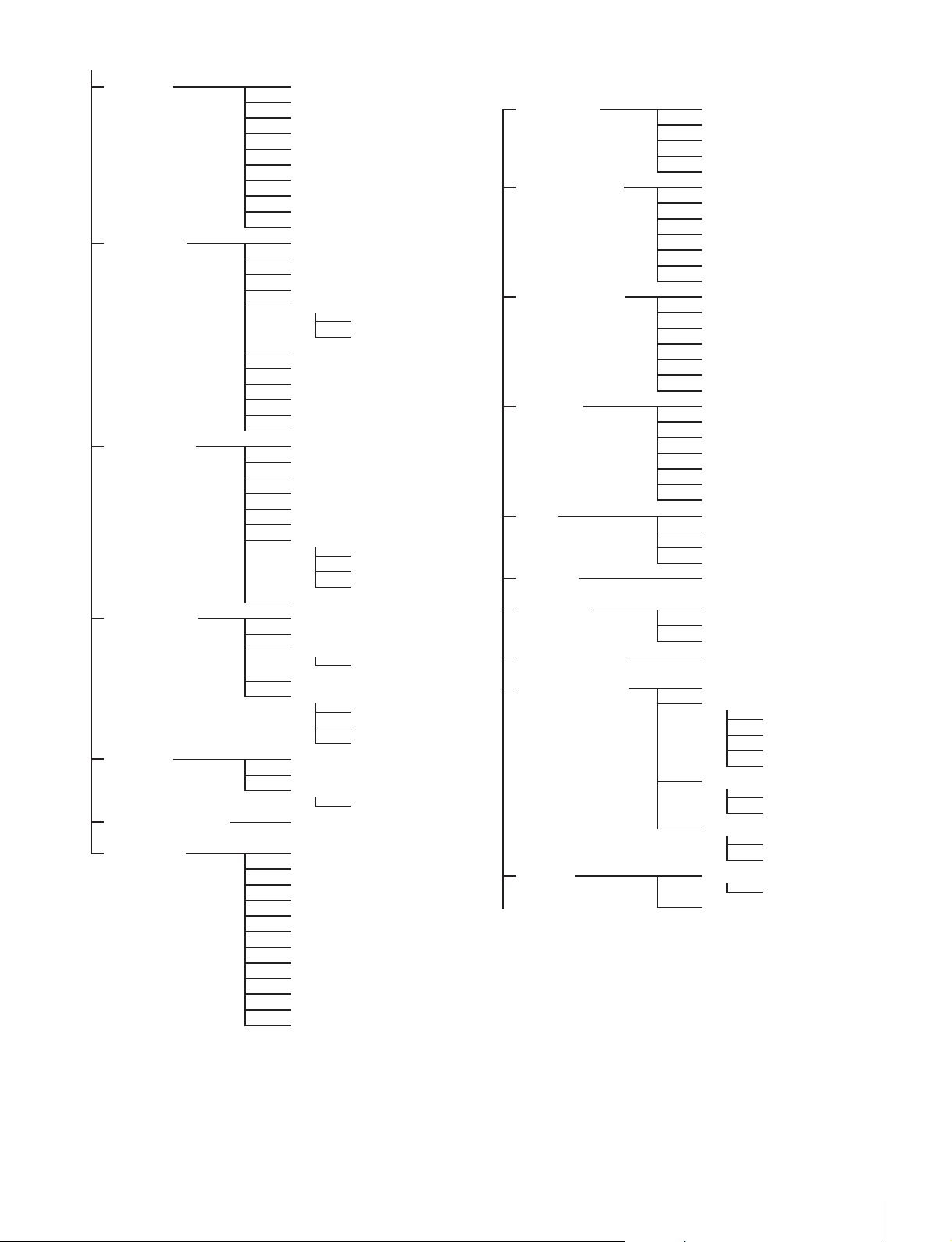
HD DETAIL
P11
SKIN DETAIL
P12
USER MATRIX
P13
MULTI MATRIX
P14
SHUTTER
P15
NOISE SUPPRESSION
P16
SCENE FILE
P17
DETAIL
LEVEL
LIMITER M
LIMITER WHT
LIMITER BLK
CRISP
LEVEL DEPEND
H/V RATIO
FREQ
ABS
SKIN DTL
SKIN GATE
ABS
NATURAL SKINDTL
ZOOM LINK
TELE
WIDE
CH SW
HUE
PHASE
WIDTH
SAT
LEVEL
R-G
R-B
G-R
G-B
B-R
B-G
MATRIX
PRESET
USER
MULTI
ADAPTIVE MATRIX
PHASE
HUE
SAT
ALL CLEAR
GATE
MATRIX
PRESET
USER
MULTI
SHUTTER
ECS FREQ
SLS
FRM
SUPPRESSION
1
2
3
4
5
STORE
STANDARD
READ
WRITE
FILE ID
CAM CODE
DATE
MAINTENANCE menu
AUTO SETUP
M01
WHITE SHADING
M02
BLACK SHADING
M03
AUTO IRIS
M04
LENS
M05
M06
CALL/TALLY
M07
OUTPUT FORMAT
M08 (U13)
PROMPTER2 OUT
M09 (U14)
SDI OUT
M10 (U15)
AUTO BLACK
AUTO WHITE
AUTO WHITE SHADING
AUTO BLACK SHADING
TEST
V SAW
V PARA
H SAW
H PARA
WHITE
AUTO WHITE SHADING
WHITE SHAD MODE
V SAW
V PARA
H SAW
H PARA
BLACK
MASTER GAIN
AUTO BLACK SHADING
AUTO IRIS
WINDOW
OVERRIDE
IRIS LEVEL
APL RATIO
IRIS GAIN
IRIS CLOSE
F N
O. DISP
LENS AUX
CAM LENS IF
AF DISPLAY
MICMIC GAIN
CCU CALL
CAM CALL
TALLY SW
CURRENT
OUTPUT
VBS-OUT
CHARACTER
GAIN
CHROMA
SETUP (SY model)
DOWN CONVERTER
SELECT
ASPECT
SYNC-OUT
V-PHASE
H-PHASE
SDI-MONI OUT
EMB AUDIO
CHARACTER
Menu List
27
Page 28

TRUNK
M11
GENLOCK
M12
AUDIO INPUT SEL
M13
F55 AUDIO SET1
M14
F55 AUDIO SET2
M15
DATE
M16
CHU MODE CURRENT
M17
OTHERS
M18
OPTION KEY
M19
REMOTE SELECT
REFERENCE
GENLOCK
PHASE
AUDIO IN
INPUT
WIND FILTER
OUTPUT
LEVEL
DATE/TIME
FILE TIMESTAMP FORMAT
PMW-F55
F65(1x, 2x)
FAN MODE
READ (USB t CAM)
INSTALLED OPTION
STATUS
FORMAT
V
H
MIC CH1 REF
MIC CH2 REF
LIMIT
CH1
CH2
CH
MONITOR
CH1 SELECT
CH2 SELECT
CH1 LEVEL
CH2 LEVEL
AGC SPEC
AGC MODE
FILE menu
OPERATOR FILE
F01
SCENE FILE
F02
REFERENCE
F03
USER GAMMA
F04
LENS FILE
F05
MATRIX
F06
FILE CLEAR
F07
READ (USB t CAM)
WRITE (CAM t USB)
PRESET
STORE PRESET FILE
FILE ID
CAM CODE
DATE
1
2
3
4
5
STORE
STANDARD
READ (USB t CAM)
WRITE (CAM t USB)
FILE ID
CAM CODE
DATE
STORE FILE
STANDARD
ALL PRESET
READ (USB t CAM)
WRITE (CAM t USB)
FILE ID
CAM CODE
DATE
READ (USB t CAM)
PRESET
FILE ID
CAM CODE
DATE
STORE FILE
No.
NAME
F NO
CENTER MARKER
H POS
V POS
STORE
CUSTOMIZE1
CUSTOMIZE2
CUSTOMIZE3
CUSTOMIZE4
CUSTOMIZE5
CUSTOMIZE CLEAR
READ (USB t CAM)
WRITE (CAM t USB)
FILE ID
CAM CODE
DATE
PRESET OPER
REFERENCE (ALL)
ATO R
10 SEC CLEAR
28
Menu List
Page 29
DIAGNOSIS menu
OPTICAL LEVEL
D01
BOARD STATUS
D02
ROM VERSION
D03 (U16)
SERIAL NO.
D04
CAM INFO
D05
CAM AUDIO SW INFO
D06
F65 STATUS
D07
CCU t CAM
CAM t CCU
t
BPU
CSA
CSA t BPU
DPR
SY
PS
TX
CAMERA APP
OS
UPDATER
SY
PROP
ENC
TX
MODEL
NO.
OPTION
MODEL
STATUS
POWER
CONNECT
INTERNAL ND
AUDIO CH1
AUDIO CH2
CH1 MIC +48V
CH2 MIC +48V
CA4000
CAM t CSA
CSA t CAM
OPERATION Menu
OPERATION
Page name
Page No.
<VF DISPLAY>
01 (U05)
Item Settings Description
EX ON
ZOOM ON, OFF
DISP LEFT, RIGT
FOCUS ON, OFF
ND ON
CC ON
5600K ON
IRIS ON
GAIN ON
SHUTTER ON
RETURN ON
TALK ON
AF ON
MESSAGE ALL
, OFF
Valid only when using a serial lens.
, OFF
, OFF
, OFF
, OFF
, OFF
, OFF
, OFF
, OFF
, OFF Displayed only when AF MODE is ON.
, WRN, AT, OFF ALL: Displays all messages.
WRN: Displays warning messages and higher.
AT: Displays Auto Setup information and higher.
Menu List
29
Page 30
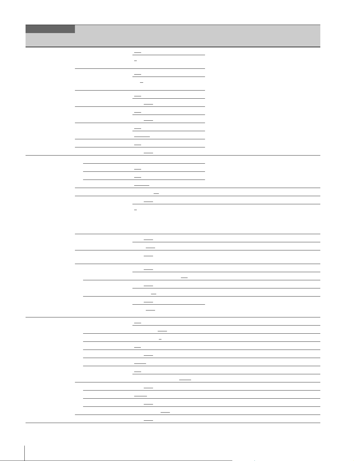
OPERATION
Page name
Page No.
<‘!’ IND>
02 (U06)
<VF MARKER>
03 (U07)
<VF DETAIL>
04 (U02)
Item Settings Description
ND ON, OFF [IND]: ‘!’ display (see page 20) on/off
, 2, 3, 4, 5 (combinations
1
supported)
CC ON
5600K ON
SHUTTER ON, OFF, ---
FAN ON, OFF
EXT ON
Y TALLY ON, OFF
MARKER Sets the display of all markers on/off.
VF-A ON
VF-B ON
LEVEL 0 to 100, 70
CENTER ON, OFF
SAFETY ZONE ON, OFF
EFFECT ON, OFF
ASPECT ON, OFF
MASK ON, OFF
SAFETY ON, OFF
VF DETAIL ON
CRISP –99 to +99, 0
FREQUENCY 9M, 14M, 18M
FLICKER ON, OFF
AREA 100%, 70%, 60%, 50%, 40%
ZOOM LINK ON
COLOR DETAIL ON, OFF, (OFF) Settings in ( ): Indicates DYNAMIC FOCUS is ON.
COLOR SEL BLUE
PEAK COLOR ON, OFF
CHROMA LEVEL 100%, 50%, 25%, 0%
DYNAMIC FOCUS ON, OFF
, OFF
A, B
, C, D, E (combinations
supported)
, OFF, ---
ON, OFF
ON, OFF
AUTO1
, AUTO2, MIN, MAX
, OFF
, OFF
, OFF
WHITE
, BLACK, DOT
1, 2, 3, 4 1: Full cross
80.0, 90.0, 92.5, 95.0%
, (FOCUS) (FOCUS): Displayed when INDICATOR in <FOCUS
16:9, 15:9, 14:9, 13:9, 4:3
0 to 15, 12 Sets the mask level outside the aspect ratio area.
, (AREA) Sets the safety marker in Aspect mode.
80.0, 90.0
0 to 100%, 25%
0%, 25%, 50%, 75%, 100%
, 92.5, 95.0%
, OFF
, OFF
, RED, YELLOW, GREEN
[NORMAL]: Specifies the conditions for which the ‘!’
display is not shown, even if [IND] is ON. (By
specifying standard items, you can receive
notifications on the ‘!’ display whenever a nonstandard item is selected.)
Ex: With the default setting of ND, the ‘!’ display will
appear when an ND filter other than 1 is selected.
---: When a CCU is connected (cannot be modified)
VF-A: HDVF-series viewfinder
VF-B: DVF-series viewfinder
2: Full cross with hole
3: Center
4: Center with hole
ASSIST> is ON.
(AREA): Displayed when AREA MARKER in <FOCUS
ASSIST> is ON.
30
Menu List
Page 31
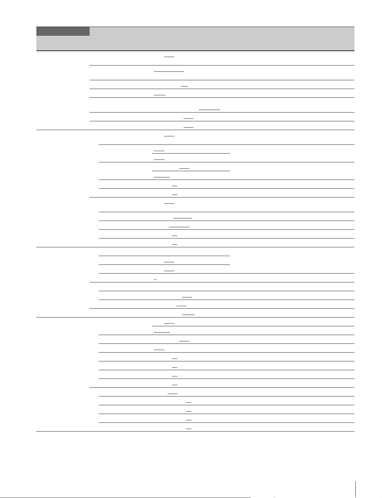
OPERATION
Page name
Page No.
<DYNAMIC FOCUS>
05 (U03)
<FOCUS ASSIST>
06 (U04)
<ZEBRA>
07 (U09)
<CURSOR>
08 (U08)
Item Settings Description
DYNAMIC FOCUS ON, OFF, (OFF) HD 4-times/6-times frame rate mode, (OFF) is
FREQUENCY EXTRA-LOW
CRISP 0% to 99%, 6%
LEVEL LOW, MID, HIGH, VERY HIGH
PEAK COLOR OFF, RED, BLUE, GREEN,
THRESHOLD 0% to 100%, 50%
CHROMA LEVEL 0% to 100%, 19%
INDICATOR ON, OFF, (EFFECT) (EFFECT): Displayed when EFFECT in <VF
MODE BOX
LEVEL 0 to 100%, 70%
GAIN 0 to 99, 50
OFFSET 0 to 99, 50
AREA MARKER ON, OFF, (ASPECT) (ASPECT): Displayed when ASPECT SAFETY in <VF
SIZE SMALL, MIDDLE
POSITION LEFT, CENTER
POSITION H 0 to 99, 50
POSITION V 0 to 99, 50
ZEBRA VF-A: HDVF-series viewfinder
VF-A ON, OFF
VF-B ON, OFF
ZEBRA1
LEVEL 50 to 109%, 70%
WIDTH 0 to 30%, 10%
ZEBRA2 50 to 109%, 100%
CURSOR ON, OFF
LEVEL 0 to 100%, 70%
BOX/CROSS BOX, CROSS
H POSITION 0 to 99, 50
V POSITION 0 to 99, 50
WIDTH 0 to 99, 50
HEIGHT 0 to 99, 50
BOX MEMORY 1/2/3: OFF, ON
H POSI 1/2/3: 0 to 99, 50
V POSI 1/2/3: 0 to 99, 50
WIDTH 1/2/3: 0 to 99, 50
HEIGHT 1/2/3: 0 to 99, 50
HIGH
BROWN, PURPLE, YELLOW
, B&W, COL
, LEFT, TOP, RIGHT
BTM
QUICK, SMOOTH
1, 2, 1&2
WHITE, BLACK, DOT
, LOW, MIDDLE,
, LARGE
, RIGHT
selected.
MARKER> is ON.
MARKER> is ON.
VF-B: DVF-series viewfinder
Menu List
31
Page 32
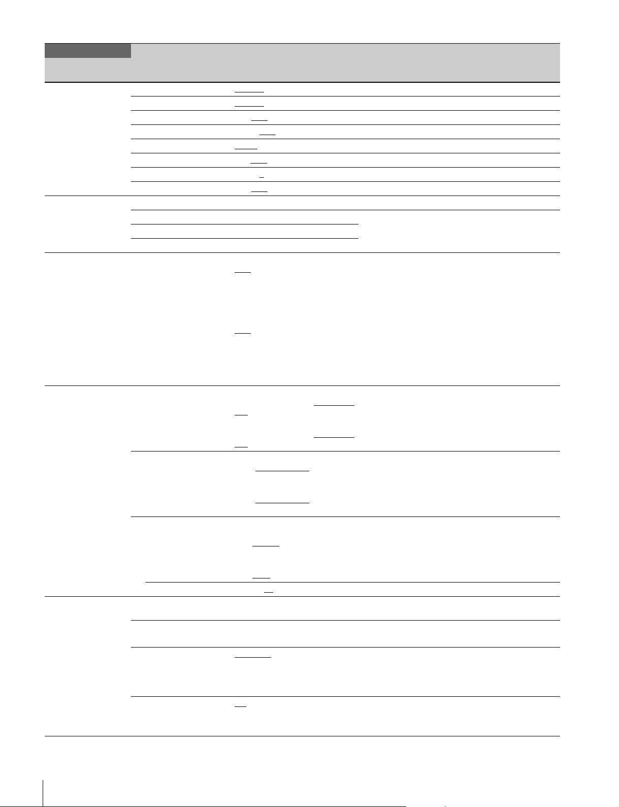
OPERATION
Page name
Page No.
<VF OUT>
09 (U01)
<VF-B SETUP>
10
<SWITCH ASSIGN1>
11 (U10)
<SWITCH ASSIGN2>
12 (U11)
<RETURN>
13
Item Settings Description
VF-A OUT COLOR, Y, R, G, B
VF-B OUT COLOR
RET MIX VF ON, OFF
MIX DIRECTION MAIN, RET
MIX VF MODE Y-MIX, WIRE(W), WIRE(B)
MIX VF LEVEL 0 to 80%
CHARACTER LEVEL 0 to 5, 5
SHRINK MODE ON, OFF
RESOLUTION Displays the resolution of the connected viewfinder.
CONTRAST –99 to +99 Display only if there is a control switch or control knob
BRIGHTNESS –99 to +99
PEAKING 0 to 99
ASSIGNABLE SY model:
LENS VTR S/S SY model:
HANDLE SW1 SY model:
HANDLE SW2 SY model:
ZOOM SPEED 0 to 99, 20
RET1 SEL CCU RET1, CCU RET2,
RET2 SEL (CCU RET2), (CCU RET3),
RET1 + RET2 RET1 SW
VBS RET ASPECT EC
, MONO
on the viewfinder.
OFF
, RETURN1 SW, INCOM, VF
DETAIL, MIX VF, 5600K, FAN
MAX, VF-A ASSIGN SW1, VF-A
ASSIGN SW2, FOCUS ASSIST
INDICATOR, DYNAMIC FOCUS
CE model:
, RETURN1 SW, ENG,
OFF
PROD, VF DETAIL, MIX VF,
5600K, FAN MAX, VF-A ASSIGN
SW1, VF-A ASSIGN SW2,
FOCUS ASSIST INDICATOR,
DYNAMIC FOCUS
Assigns a function to the lens VTR START/STOP
OFF, RETURN1 SW, RETURN2
SW, INCOM
CE model:
OFF, RETURN1 SW, RETURN2
SW, ENG, PROD
OFF, RETURN1 SW
SW, INCOM, ZOOM(T)
CE model:
OFF, RETURN1 SW
SW, ENG, PROD, ZOOM(T)
OFF, RETURN1 SW, RETURN2
SW, INCOM
CE model:
OFF, RETURN1 SW, RETURN2
SW, ENG
CCU RET3, CCU RET4
(CCU RET4)
, PROD, ZOOM(W)
, RET3 SW Switch operation when the RET1 button and RET2
, SQ Sets the VBS RET aspect ratio in standalone mode.
, RETURN2
, RETURN2
, ZOOM(W)
switch.
Enabled when LENS AUX is ON.
If CCU is not connected: BPU RET1 and BPU RET2
Fixed by the RET2-4 switch.
If CCU is not connected: BPU RET2
button are pressed at the same time.
RET1 SW: Operates as RET1 button.
RET3 SW: Operates as RET3 button
EC: Edge Crop
SQ: SQueeze
32
Menu List
Page 33
OPERATION
Page name
Page No.
<HEADSET MIC>
14 (U12)
<INTERCOM>
15
<TRACKER>
16
<OPERATOR FILE>17READ (USBtCAM) ENTER to execute Reads the operator file from a USB flash drive.
Item Settings Description
INTERCOM MIC DYNAMIC, CARBON, MANUAL
LEVEL –60 dB, –50 dB, –40 dB, –30 dB,
POWER ON, OFF, (ON), (OFF)
UNBAL ON, OFF, (ON)
INTERCOM RECEIVE
SELECT
INTERCOM ---, LEFT
ENG ---, LEFT
PROD ---, LEFT
PGM1 ---, LEFT, RIGHT
PGM2 ---, LEFT, RIGHT
TRACKER ---, LEFT
SIDE TONE MU, 1 to 99, 50
TRACKER RECEIVE
SELECT
INTERCOM ---, LEFT
ENG ---, LEFT
PROD ---, LEFT
PGM1 ---, LEFT, RIGHT
PGM2 ---, LEFT, RIGHT
INPUT LEVEL –20 dBu, 0 dBu
OUTPUT LEVEL L-CH 0 dBu
OUTPUT LEVEL R-CH
WRITE (CAMtUSB) ENTER to execute Writes the current operator file item settings to a USB
PRESET ENTER to execute Loads the operator file data stored in internal memory.
FILE ID 16 characters (max.) Enters a comment in the operator file to save to a USB
CAM CODE Video camera code Display only
DATE Date Display only
–20 dB, (–60 dB)
(–40 dB), (–30 dB), (–20 dB)
, 6 dB Input gain
–6, 0
SEPARATE
SEPARATE, MIX
–6 dBu, 0 dBu, 6 dBu
, –6 dBu, –12 dBu,
–18 dBu, –20 dBu, –24 dBu
, (–50 dB),
, (OFF) Settings in ( ): When CARBON is selected (cannot be
, MIX
, RIGHT, BOTH SY model only
, RIGHT, BOTH CE model only
, RIGHT, BOTH CE model only
, BOTH
, BOTH
, RIGHT, BOTH
, RIGHT, BOTH SY model only
, RIGHT, BOTH CE model only
, RIGHT, BOTH CE model only
, BOTH
, BOTH
Settings in ( ): When DYNAMIC or CARBON is
selected (cannot be modified)
Settings in ( ): When DYNAMIC or CARBON is
selected (cannot be modified)
modified)
flash drive.
flash drive.
See “To enter a character string” (page 22).
Menu List
33
Page 34
PAINT Menu
PA IN T
Page name
Page No.
<SW STATUS>
P01
<VIDEO LEVEL>
P02
<COLOR TEMP>
P03
<GAMMA>
P04
<BLACK GAMMA>
P05
Item Settings Description
FLARE ON
GAMMA ON
BLK GAM ON, OFF
KNEE ON, OFF
WHT CLIP ON
DETAIL ON
LVL DEP ON
SKIN DTL ON, OFF
MATRIX ON, OFF
WHITE R/G/B: –99 to +99, 0 R, G, B, and M (master) values can be independently
BLACK R/G/B/M: –99 to +99, 0
FLARE R/G/B/M: –99 to +99, 0
GAMMA R/G/B/M: –99 to +99, 0
FLARE ON, OFF
TEST OFF
WHITE R/G/B: –99 to +99, 0
AUTO WHITE
BALANCE
COLOR TEMP 0 K to 65535 K, 3200 K
BALANCE –99 to +99, 0
MASTER –3.0 dB to +12.0 dB, 0.0 dB
LEVEL R/G/B/M: –99 to +99, 0 R, G, B, and M (master) values can be independently
COARSE 0.35 to 0.90 (0.05 steps), 0.45
TABLE STANDARD, HYPER, USER
GAMMA ON
TEST OFF
LEVEL R/G/B/M: –99 to +99, 0
RANGE LOW, L.MID, H.MID, HIGH
TEST OFF, SAW, 3STEP, 10STEP
, OFF
, OFF
, OFF
, OFF
, OFF
, SAW, 10STEP
ENTER to execute
1, 2, 3, 4, 5
1, 2, 3, 4
ON, OFF
, 6, 7 When STANDARD or USER is selected
, OFF
, SAW, 10 STEP
set.
(M cannot be set for WHITE.)
set.
(USER: 1 to 5 only)
1: Camcorder equivalent
2: ×4.5 gain
3: ×3.5 gain
4: SMPTE-240M equivalent
5: ITU-R709 equivalent
6: ×5.0 gain
7: ×5.0–709
When HYPER is selected.
1: 325% to 100%
2: 460% to 100%
3: 325% to 109%
4: 460% to 109%
R, G, B, and M (master) values can be independently
set.
34
Menu List
Page 35
PA IN T
Page name
Page No.
<SATURATION>
P06
<KNEE>
P07
<WHITE CLIP>
P08
<DETAIL 1>
P09
<DETAIL 2>
P10
Item Settings Description
SATURATION –99 to +99, 0
ON, OFF
LOW KEY SAT –99 to +99, 0
RANGE LOW, L.MID, H.MID, HIGH
ON, OFF
TEST OFF, SAW, 3STEP, 10STEP
K POINT R/G/B/M: –99 to +99, 0
K SLOPE R/G/B/M: –99 to +99, 0
KNEE ON, OFF
KNEE MAX ON, OFF
KNEE SAT –99 to +99, 0
ON, OFF
AUTO KNEE OFF, AUTO
POINT LIMIT –99 to +99, 0
SLOPE –99 to +99, 0
ABS Highlighted: ABS (absolute value) mode
W CLIP –99 to +99, 0
ON, OFF
ABS Highlighted: ABS (absolute value) mode
DETAIL ON
LEVEL –99 to +99, 0
LIMITER M –99 to +99, 0
LIMITER WHT –99 to +99, 0 Absolute value is displayed in ABS mode
LIMITER BLK –99 to +99, 0
CRISP –99 to +99, 0
LEVEL DEPEND –99 to +99, 0
ABS Highlighted: ABS (absolute value) mode
H/V RATIO –99 to +99, 0
FREQ –99 to +99, 0
MIX RATIO –99 to +99, 0
KNEE APT –99 to +99, 0
DTL H/V MODE H/V, V only
ABS Highlighted: ABS (absolute value) mode
, OFF
ON
, OFF
ON, OFF
R, G, B, and M (master) values can be independently
set.
Absolute values are displayed in ABS mode, except
for M (master).
Absolute value is displayed in ABS mode
Absolute value is displayed in ABS mode
Absolute value is displayed in ABS mode
Absolute value is displayed in ABS mode
Absolute value is displayed in ABS mode
Absolute value is displayed in ABS mode
Absolute value is displayed in ABS mode
Absolute value is displayed in ABS mode
Absolute value is displayed in ABS mode
Absolute value is displayed in ABS mode
Menu List
35
Page 36
PA IN T
Page name
Page No.
<HD DETAIL>
P11
<SKIN DETAIL>
P12
<USER MATRIX>
P13
Item Settings Description
DETAIL ON, OFF
LEVEL –99 to +99, 0
LIMITER M –99 to +99, 0
LIMITER WHT –99 to +99, 0 Absolute value is displayed in ABS mode
LIMITER BLK –99 to +99, 0
CRISP –99 to +99, 0
LEVEL DEPEND –99 to +99, 0
, OFF
ON
H/V RATIO –99 to +99, 0
FREQ –99 to +99, 0
ABS Highlighted: ABS (absolute value) mode
SKIN DTL ON, OFF
SKIN GATE OFF, 1, 2, 3, (MAT) 1, 2, 3: The skin gate function can be turned on for the
ABS Highlighted: ABS (absolute value) mode
NATURAL SKINDTL OFF
ZOOM LINK OFF
TELE 0 to 99
WIDE 0 to 99
CH SW 1: (ON), 2/3: ON, OFF
HUE 1/2/3: ENTER to execute
PHASE 1/2/3: 0
WIDTH 1/2/3: 0 to 90, 29
SAT 1/2/3: –99 to +99, –89
LEVEL 1/2/3: –99 to +99, 0
R-G –99 to +99, 0
R-B –99 to +99, 0
G-R –99 to +99, 0
G-B –99 to +99, 0
B-R –99 to +99, 0
B-G –99 to +99, 0
MATRIX ON, OFF
PRESET ON, OFF
USER ON, OFF
MULTI ON, OFF
ADAPTIVE MATRIX OFF, ON
, ON
, ON
to 359
SMPTE-240M, ITU-709
WIDE, NTSC, EBU, ITU-601
, SMPTE-
Absolute value is displayed in ABS mode
Absolute value is displayed in ABS mode
Absolute value is displayed in ABS mode
Absolute value is displayed in ABS mode
Absolute value is displayed in ABS mode
Absolute value is displayed in ABS mode
specified channel only.
(MAT): Displayed when GATE in <MULTI MATRIX> is
ON.
Sets the skin tone detail function independently for
each channel (channel 1 is always ON).
Absolute value is displayed for LEVEL only in ABS
mode
36
Menu List
Page 37
PA IN T
Page name
Page No.
<MULTI MATRIX>
P14
<SHUTTER>
P15
<NOISE
SUPPRESSION> P16
Item Settings Description
PHASE 0, 23, 45, 68, 90, 113, 135, 158,
HUE –99 to +99, 0
SAT –99 to +99, 0
ALL CLEAR ENTER to execute
GATE ON, OFF
MATRIX ON, OFF
PRESET ON, OFF
USER ON, OFF
MULTI ON, OFF
SHUTTER ON, OFF, (ON), (OFF) Settings in ( ): When a remote control unit/panel or
ECS FREQ 59.94P: 1/60.07 to 1/8000
SLS ON, OFF
FRM 2
SUPPRESSION 20
180, 203, 225, 248, 270, 293,
315, 338
, (SKN) (SKN): Displayed when SKIN GATE in <SKIN
SMPTE-240M, ITU-709
WIDE, NTSC, EBU, ITU-601
59.94P: 1/100, 1/120, 1/125,
1/250, 1/500, 1/1000, 1/2000,
1/4000
59.94i: 1/100
1/250, 1/500, 1/1000, 1/2000,
1/4000
50P: 1/60, 1/100, 1/120, 1/125,
1/250, 1/500, 1/1000, 1/2000
50i: 1/60, 1/100, 1/120, 1/125,
1/250, 1/500, 1/1000, 1/2000
29.97P: 1/50, 1/60, 1/120, 1/125,
1/250, 1/500, 1/1000, 1/2000
25P: 1/30, 1/50, 1/60, 1/100,
1/250, 1/500, 1/1000, 1/2000
24P/23.98P: 1/48, 1/50, 1/60,
1/120, 1/250, 1/500, 1/1000,
1/2000
59.94i: 1/60.1 to 1/7000
50P: 1/50.03 to 1/7000
50i: 1/50.14 to 1/7000
29.97P: 1/29.99 to 1/8000
25P: 1/25.02 to 1/7000
24P/23.98P: 1/23.99 to 1/6000
to 8 Sets the number of accumulated frames of the slow
, 50, 80%
ON, OFF
, 1/120, 1/125,
, SMPTE-
Select the axis (angle) for which to adjust the
multimatrix correction function, and set HUE and SAT.
(HUE and SAT can be adjusted independently for 16
axes.)
DETAIL> is ON.
CCU is not connected (cannot be modified)
Shutter step selection
Turns the slow shutter function on/off.
Disabled when CHU MODE is set to F65.
shutter function.
Menu List
37
Page 38
PA IN T
Page name
Page No.
<SCENE FILE>
P17
Item Settings Description
1 Stores and reads scene files (paint data):
2
3
4
5
STORE ENTER to execute
STANDARD ENTER to execute Loads the standard paint data.
READ ENTER to execute Reads five scene files from a USB flash drive into
WRITE ENTER to execute Writes five scene files from internal memory to a USB
FILE ID 16 characters (max.) Enters a comment in the scene file to save to a USB
CAM CODE Video camera code Display only
DATE Date Display only
MAINTENANCE Menu
To store a file in internal memory, specify the number
after executing STORE.
To read a file, specify the file number only.
internal memory.
flash drive.
flash drive.
See “To enter a character string” (page 22).
MAINTENANCE
Page name
Page No.
<AUTO SETUP>
M01
<WHITE SHADING>
M02
<BLACK SHADING>
M03
Item Settings Description
AUTO BLACK ENTER to execute Disabled when CHU MODE is set to F65.
AUTO WHITE ENTER to execute
AUTO WHITE SHADING ENTER to execute
AUTO BLACK SHADING ENTER to execute Disabled when CHU MODE is set to F65.
TEST OFF
V SAW R/G/B: –99 to +99, 0
V PARA R/G/B: –99 to +99, 0
H SAW R/G/B: –99 to +99, 0
H PARA R/G/B: –99 to +99, 0
WHITE R/G/B: –99 to +99, 0
AUTO WHITE SHADING ENTER to execute
WHITE SHAD MODE RGB, RB
V SAW R/G/B: –99 to +99, 0 R, G, and B values can be independently set.
V PARA R/G/B: –99 to +99, 0
H SAW R/G/B: –99 to +99, 0
H PARA R/G/B: –99 to +99, 0
BLACK R/G/B/M: –99 to +99, 0
MASTER GAIN –3, 0, 3, 6, 9, 12 dB
AUTO BLACK SHADING ENTER to execute
, SAW, 10STEP
R, G, and B values can be independently set.
M (master) value can also be set for BLACK.
38
Menu List
Page 39
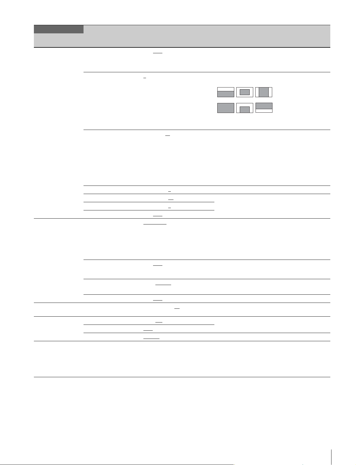
MAINTENANCE
Page name
Page No.
<AUTO IRIS>
M04
<LENS>
M05
<MIC GAIN>
M06
<CALL/TALLY>
M07
<OUTPUT FORMAT>
M08 (U13)
Item Settings Description
AUTO IRIS ON, OFF, (ON), (OFF) Settings in ( ): When a remote control unit/panel or
WINDOW 1
OVERRIDE –99 to 99, ---
IRIS LEVEL –99 to +99, 0
APL RATIO –99 to +99, 65
IRIS GAIN –99 to +99, 0
IRIS CLOSE ON, OFF
F NO. DISP CONTROL, RETURN Switches the iris indicator on the panel when AUTO
LENS AUX ON, OFF
CAM LENS IF OFF, Type-C
AF DISPLAY ON, OFF
MIC 20, 30, 40, 50, 60
CCU CALL OFF, ON
CAM CALL OFF
TALLY SW FRONT
CURRENT 1080-59.94P, 1080-50P,
, 2, 3, 4, 5, 6 Selects the auto iris detection window.
, Type-A,
Type-C+12P, Type-A+12P
dB Valid only in standalone mode.
, --- ---: When a CCU is not connected (cannot be
, ON, ---
, REAR, BOTH
1080-29.97P, 1080-25P,
1080-24P, 1080-23.98P,
59.94P (4x), 59.94P (6x),
59.94P (2x), 50P (4x), 50P (6x),
50P (2x)
CCU is not connected, when CHU MODE is set to
F65 and LENS AUX is OFF, and in 4-times/6-times
frame rate modes (cannot be modified).
123
456
Light is detected in the shaded areas.
When LENS AUX is ON.
Temporarily changes the auto iris level brightness
standard by up to ±2 stops.
–99: Closes the iris 2 stops
99: Opens the iris 2 stops
--- : OFF
The setting returns to “---” when the power is turned
off.
When LENS AUX is ON.
±4 stops, when LENS AUX is ON.
When LENS AUX is ON.
IRIS is off.
CONTROL: Displays the value from the camera.
RETURN: Displays the return value from the lens.
(When AUTO IRIS is on, always displays the return
value from the lens.)
ON: When a lens is connected to the AUX connector
on the rear panel. The CA unit must be rebooted
after changing settings.
Sets the type of lens connected to the PMW-F55.
Enabled when CHU MODE is set to F55.
Enabled only when an AF lens is connected.
modified)
Displays the current format.
Menu List
39
Page 40
MAINTENANCE
Page name
Page No.
<PROMPTER2 OUT>
M09 (U14)
<SDI OUT>
M10 (U15)
<TRUNK>
M11
<GENLOCK>
M12
<AUDIO INPUT SEL>
M13
<F55 AUDIO SET1>
M14
Item Settings Description
OUTPUT PROMPTER2, SD-SYNC,
VBS-OUT Displayed when OUTPUT is VBS.
CHARACTER ON, OFF
GAIN –99 to +99, 0
CHROMA –99 to +99, 0
SETUP ON, OFF Displayed when format is NTSC (SY model).
DOWN CONVERTER Displayed when OUTPUT is VBS.
SELECT MAIN
ASPECT SQ
SYNC-OUT Displayed when OUTPUT is SD-SYNC or HD-SYNC.
V-PHASE –999 to +999, 0
H-PHASE –999 to +999, 0
SDI-MONI OUT MAIN, VF, RET, HD-PROMPT,
CHARACTER ON, OFF
EMB AUDIO OFF, F55 MIC, CA MIC, PGM
REMOTE SELECT RM
REFERENCE CCU, INTERNAL, GENLOCK Displays sync status
GENLOCK ENABLE
STATUS
FORMAT
PHASE
V –1024 to +1023, 0
H –1700 to +1700, 0
AUDIO IN F55, CA, MIC-F55 AES-CA Selects the audio signal input.
INPUT Enabled only when CHU MODE is set to F55.
MIC CH1 REF –60dB, –50dB
MIC CH2 REF –60dB, –50dB
LIMIT OFF
WIND FILTER Turns the Window Filter function on/off.
CH1 OFF
CH2 OFF
OUTPUT
CH CH1/CH2
MONITOR CH1/CH2
HD-SYNC, VF
, RET, VF
, EC
OFF
(1-MIC1 2- ---) Display only
(3-AES1 4-AES2) Display only
(1-PGM1 2-PGM2) Display only
(3-ENG 4-PROD) Display only
, TRUNK
, –6dB, –9dB, –12dB, –15dB,
–17dB
, ON
, ON
, VBS
, DISABLE Not displayed when a CCU or BPU is connected.
, –40dB Selects the reference input level when the AUDIO IN
, –40dB Selects the reference input level when the AUDIO IN
, CH1, CH2 Selects the monitor audio output.
Note
VBS output is not supported when the format is
23.98P or 24P.
Only CA is enabled when CHU MODE is set to F65.
CH1 switch is set to MIC.
CH2 switch is set to MIC.
Selects the limiter characteristic (saturation level) for
strong input signals when adjusting the audio input
level manually.
OFF: Do not use limiter.
Selects the audio output.
40
Menu List
Page 41

MAINTENANCE
Page name
Page No.
<F55 AUDIO SET2>
M15
<DATE>
M16
<CHU MODE>
M17
<OTHERS>
M18
<OPTION KEY>
M19
Item Settings Description
LEVEL Set to AUTO to automatically adjust the recording
CH1 SELECT AUTO
CH2 SELECT AUTO
CH1 LEVEL –99 to +99, ±0
CH2 LEVEL –99 to +99, ±0
AGC SPEC –6dB, –9dB, –12dB, –15dB,
AGC MODE MONO
DATE/TIME 2000 to 2099/01 to 12/00 to 31
FILE TIMESTAMP
FORMAT
CURRENT PMW-F55
PMW-F55 ENTER to execute Sets camera head unit to PMW-F55.
F65(1x, 2x) ENTER to execute Sets camera head unit to F65 (normal speed, 2x frame
FAN MODE OFF, AUTO1, AUTO2, MIN, MAX AUTO1: Normal-speed rotation
READ (USBtCAM) ENTER to execute Reads the install key from a USB flash drive.
INSTALLED OPTION Displayed only when an option has been installed.
, MANUAL
, MANUAL
–17dB
, STEREO Selects the AGC mode for adjusting the input level of
00 to 23: 00 to 59
1 Y/Mn/D, 2 Mn/D, 3 D/M/Y
4 D/M, 5 M/D/Y
, 6 M/D
, F65(1x ,2x) Currently selected camera head setting
level.
Enabled only when CHU MODE is set to F55.
Adjusts the recording level when SELECT for the
corresponding channel is set to MANUAL.
Selects the AGC characteristic (saturation level).
the analog audio signal to record on channels 1 and 2.
MONO: Each channel is adjusted independently.
STEREO: Channels adjusted in stereo mode.
Y: Year
Mn: Month (numeric)
Mn: Month (English abbreviation)
D: Day
rate).
AUTO2: Slow speed rotation
Menu List
41
Page 42
FILE Menu
Six types of files can be used for easy adjustments of the
camera; Operator, Reference, Scene, User gamma, Lens,
and Custom matrix files.
You can store the items set with the OPERATION menu and
customized USER menu in the Operator file.
For details about the specific items included in these files, refer
to the Maintenance Manual.
FILE
Page name
Page No.
<OPERATOR FILE>
F01
<SCENE FILE>
F02
<REFERENCE>
F03
Item Settings Description
READ (USBtCAM) ENTER to execute Reads the operator file from a USB flash drive.
WRITE (CAMtUSB) ENTER to execute Writes the current operator file item settings to a USB
PRESET ENTER to execute Loads the operator file data stored in internal memory.
STORE PRESET FILE ENTER to execute Writes the current operator file item settings to the
FILE ID 16 characters (max.) Enters a comment in the operator file to save to a USB
CAM CODE Video camera code Display only
DATE Date Display only
1 Stores and reads scene files (paint data):
2
3
4
5
STORE ENTER to execute
STANDARD ENTER to execute Loads the standard paint data.
READ (USBtCAM) ENTER to execute Reads five scene files from a USB flash drive into
WRITE (CAMtUSB) ENTER to execute Writes five scene files from internal memory to a USB
FILE ID 16 characters (max.) Enters a comment in the scene file to save to a USB
CAM CODE Video camera code Display only
DATE Date Display only
STORE FILE ENTER to execute Writes the current settings of the reference file items to
STANDARD ENTER to execute Loads the reference file stored in internal memory.
ALL PRESET ENTER to execute Restores the reference file stored in internal memory
READ (USBtCAM) ENTER to execute Reads the reference file from a USB flash drive.
WRITE (CAMtUSB) ENTER to execute Writes the current status of reference file items to a
FILE ID 16 characters (max.) Enters a comment in the reference file to save to a
CAM CODE Video camera code Display only
DATE Date Display only
flash drive.
operator file in internal memory.
flash drive.
See “To enter a character string” (page 22).
To store a file in internal memory, specify the number
after executing STORE.
To read a file, specify the file number only.
internal memory.
flash drive.
flash drive.
See “To enter a character string” (page 22).
the reference file in internal memory.
to factory default settings. The CA unit must be
rebooted after the command is executed.
USB flash drive.
USB flash drive.
See “To enter a character string” (page 22).
42
Menu List
Page 43
FILE
Page name
Page No.
<USER GAMMA>
F04
<LENS FILE>
F05
<MATRIX>
F06
<FILE CLEAR>
F07
Item Settings Description
READ (USBtCAM) ENTER to execute Reads the user gamma file from a USB flash drive.
PRESET ENTER to execute Loads the user gamma file data stored in internal
FILE ID 16 characters (max.) Enters a comment in the user gamma file to save to a
CAM CODE Video camera code Display only
DATE Date Display only
STORE FILE ENTER to execute
No. 1 to 17, 1
NAME Can be modified only when using a serial lens.
F NO F1.0 to F3.4, F1.5
CENTER MARKER Sets and stores the center marker position.
H POS –20 to +20, 0
V POS –20 to +20, 0
STORE ENTER to execute
CUSTOMIZE 1/2/3/4/5: ENTER to execute Stores the current multimatrix data in the custom
CUSTOMIZE CLEAR ENTER to execute Clears the custom matrix file stored in internal
READ (USBtCAM) ENTER to execute Reads the matrix file from a USB flash drive.
WRITE (CAMtUSB) ENTER to execute Writes the current status of matrix file items to a USB
FILE ID 16 characters (max.) Enters a comment in the scene file to save to a USB
CAM CODE Video camera code Display only
DATE Date Display only
PRESET OPERATOR ENTER to execute
REFERENCE (ALL) ENTER to execute
10 SEC CLEAR ON, OFF
memory.
USB flash drive.
See “To enter a character string” (page 22).
1 to 16: When using a non-serial lens
17: When using a serial lens
Can be modified only when using a serial lens.
H POS: Increasing the value moves the position to the
right.
V POS: Increasing the value moves the position
downwards.
matrix file in internal memory.
memory.
flash drive.
flash drive.
See “To enter a character string” (page 22).
Sets the function when clearing the selected menu
item to ON/OFF.
See “To restore a setting to its standard value”
(page 22).
Menu List
43
Page 44
DIAGNOSIS Menu
This is a display-only menu, and cannot be used to set video camera functions.
However, some items set conditions for displaying items.
DIAGNOSIS
Page name
Page No.
<OPTICAL LEVEL>
D01
<BOARD STATUS>
D02
<ROM VERSION>
D03 (U16)
<SERIAL No.>
D04
<CAM INFO>
D05
<CAM AUDIO SW
INFO>
D06
<F65 STATUS>
D07
Item Indication Description
CCUtCAM GREEN, YELLOW, RED, NG, NO SIGNAL Displayed only when a CCU is connected
CAMtCCU GREEN, YELLOW, RED, NG, NO SIGNAL Displayed only when a CCU is connected
BPUtCSA GREEN, YELLOW, RED, NG, NO SIGNAL Displayed only when a BPU is connected
CSAtBPU GREEN, YELLOW, RED, NG, NO SIGNAL Displayed only when a BPU is connected
DPR OK, NG
SY OK, NG
PS OK, NG
TX OK, NG
CAMERA APP Vx.xx
OS Vx.xx
UPDATER Vx.xx
SY Vx.xx
PROP Vx.xx
ENC Vx.xx
TX Vx.xx
MODEL CA4000
NO. xxxxxxx
OPTION Displays option functions if any option is
MODEL PMW-F55, F65 Displays the connected camera setting.
STATUS OK, NG Displays the camera status.
POWER ON, OFF Displays the camera’s power supply status
CONNECT OK, NG Displays the status of connections with the
INTERNAL ND (CLEAR), (0.9), (1.8) Displays the status of the PMW-F55 internal
AUDIO CH1 (LINE), (MIC), (AES/EBU) Displays the AUDIO SW status on the
AUDIO CH2 (LINE), (MIC), (AES/EBU)
CH1 MIC +48V (OFF), (ON)
CH2 MIC +48V (OFF), (ON)
CA4000
AUDIO (MIC), (AES/EBU), (LINE) Displays the CA audio input selector switch
+48V (OFF), (ON) Displays the CA microphone power switch
CAMtCSA OK, CARE, NG, NO SIGNAL Displayed only when CHU MODE is set to
CSAtCAM OK, CARE, NG, NO SIGNAL
installed.
camera.
ND filter.
Displayed only when CHU MODE is set to
F55.
PMW-F55 (cannot be modified).
Displayed only when CHU MODE is set to
F55.
status (cannot be modified).
status (cannot be modified).
F65.
44
Menu List
Page 45
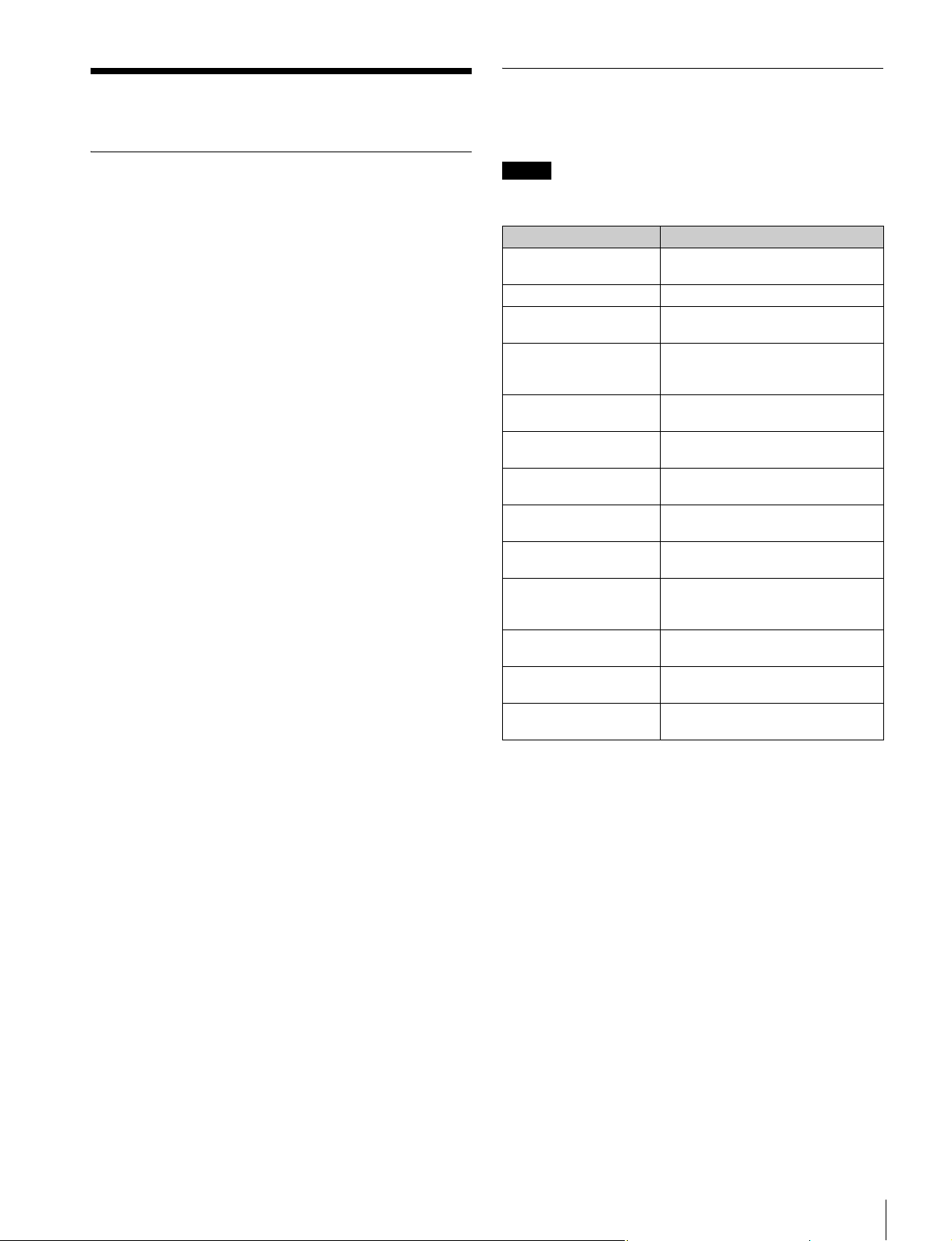
Appendix
Error Messages
If a problem occurs during operation, the following messages
may be displayed.
Precautions
The fan and battery are consumable parts that will need
periodic replacement.
When operating at room temperature, a normal replacement
cycle will be about 5 years.
However, this replacement cycle represents only a general
guideline and does not imply that the life expectancy of these
parts is guaranteed. For details on parts replacement, contact
your dealer.
The life expectancy of the electrolytic capacitor is about
5 years under normal operating temperatures and normal
usage (8 hours per day; 25 days per month). If usage exceeds
the above normal usage frequency, the life expectancy may
be reduced correspondingly.
Do not subject to severe shocks
Damage to the case or internal components may result.
When finished using
Set the power switch to OFF.
Operation and storage environment
Store in a level place with air conditioning.
If the unit gets wet, make sure it is completely dry before
storage.
Avoid use or storage in the following places:
• Extremely hot or cold places
• Places with high humidity
• Places with strong vibration
• Near strong magnetic fields
• In places where it receives much direct sunlight, or near
heating equipment
Note
To display a message, set the DISPLAY/MENU switch to
DISPLAY or MENU.
Message Meaning
TEMP WARNING The internal temperature is abnormally
FAN STOP The built-in fan is not rotating properly.
SET SYSTEM CLOCK The time and date of the internal clock
NO USB FLASH DRIVE A USB flash drive operation was
USB FLASH DRIVE
ERROR
FORMAT ERROR! An attempt was made to access an
WRITE PROTECTED A file write operation was attempted
FILE ERROR An error occurred while reading a file
OTHER MODEL’S FILE An attempt was made to read a file
FILE NOT FOUND An attempt was made to read a file
ADAPTOR FAN STOP The SKC-4065 internal fan is not
PLEASE CONFIRM CHU
MODE
PLEASE UPDATE BPU
SOFTWARE
high.
have not been set.
attempted with no USB flash drive
connected.
An error occurred during access to a
USB flash drive.
unformatted USB flash drive.
with a write-protected USB flash drive.
from a USB flash drive.
from another incompatible model.
that does not exist on the USB flash
drive.
operating.
The CHU MODE setting does not
match the connected camera head.
The BPU4000 and CA4000 software
versions do not match.
Condensation
If the unit is suddenly taken from a cold to a warm location, or
if ambient temperature suddenly rises, moisture may form on
the outer surface of the unit and/or inside of the unit. This is
known as condensation. If condensation occurs, turn off the
unit and wait until the condensation clears before operating
the unit. Operating the unit while condensation is present may
damage the unit.
Appendix
45
Page 46
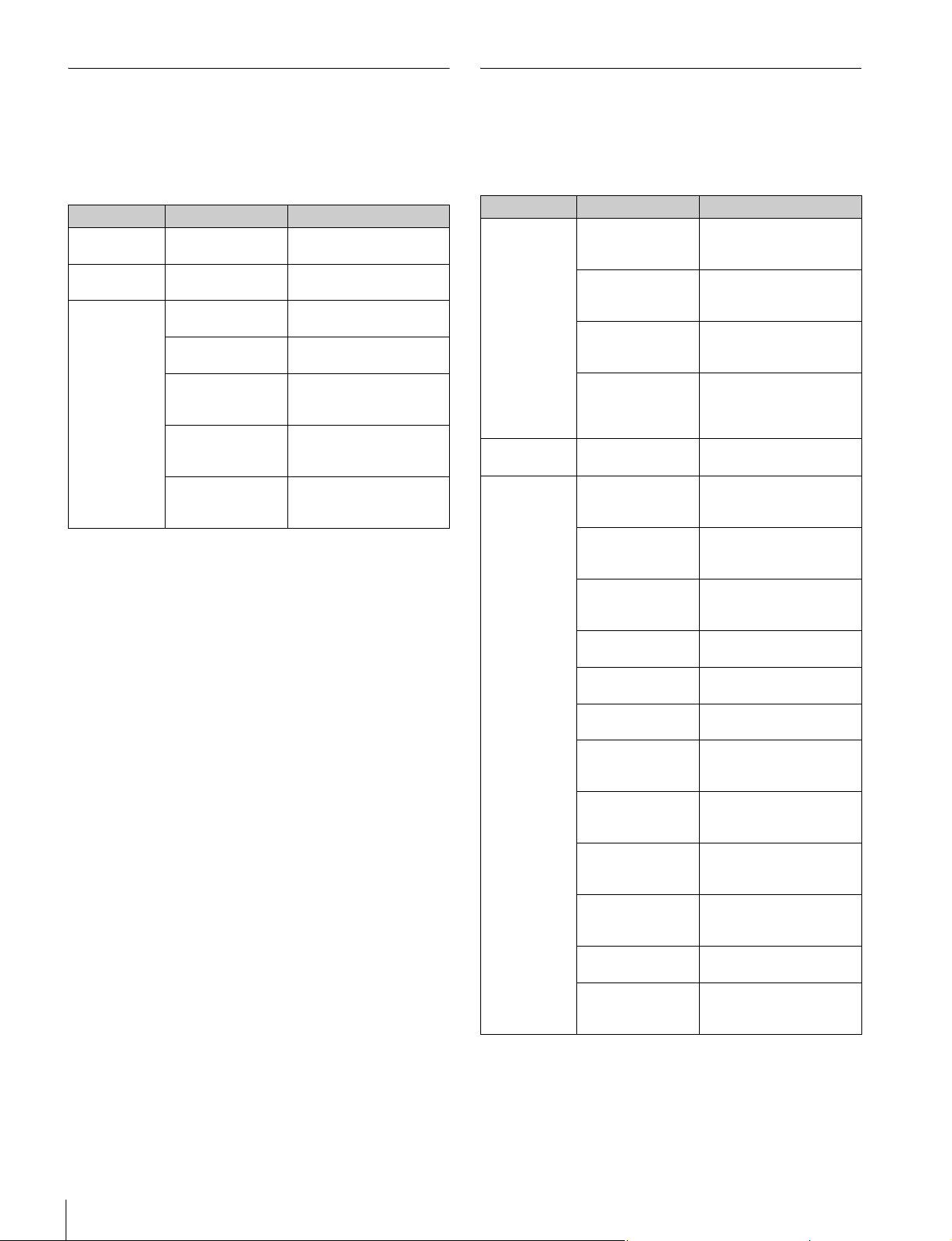
PMW-F55 Warning and Error Messages
F65 Warning and Error Messages
If a problem occurs on the PMW-F55, the following warning
and error messages may be displayed in the viewfinder.
For details about messages, refer to the PMW-F55 operating
instructions.
Message type Message Meaning
Warning CAM: TEMP HIGH The internal temperature is
Error CAM: Exx-xxx
(ex: E95-207)
Status CAM: FAN
STOPPED
CAM: BACKUP
BATT END
CAM: OPT
LOWPASS
CAM: ABNORMAL
LENS
CAM: PLEASE
EXEC ABB
abnormally high.
A hardware or other error
occurred.
The cooling fan stopped
abnormally.
The backup battery is low
on charge.
The optical lowpass filter
does not match the [High
Frame Rate Mode] setting.
The lens type setting and
the connected lens type are
different.
The ABB (auto black
balance) requires
adjustment.
If a problem occurs on the F65, the following warning and error
messages may be displayed in the viewfinder.
For details about messages, refer to the F65 operating
instructions.
Message type Message Meaning
Warning CAM:
TEMPERATURE
CARE
CAM: 12V
BATTERY (NEAR
END)
CAM: 24V
BATTERY (NEAR
END)
CAM: OPTICAL
LEVEL CARE
Error CAM: DIGITAL VF
ERROR
Status CAM: 12V
BATTERY (END)
CAM: 24V
BATTERY (END)
CAM:
TEMPERATURE
NG!
CAM: FAN1 NG! Fan 1 at the top has
CAM: FAN2 NG! Fan 2 at the top has
CAM: SYNC
ERROR
CAM: OPTICAL
LEVEL NG!
CAM: OPTICAL
LEVEL NO INPUT
CAM: CRCC
ERROR
OCCURRED
CAM:
UNSUPPORTED
DIGITAL VF
CAM: M.SHUTTER
NG!
CAM: M.SHUTTER
NOT LOCKED
The internal temperature of
the camera is close to the
upper limit.
The voltage of the 12 V
supply has fallen to the
specified Near End value.
The voltage of the 24 V
supply has fallen to the
specified Near End value.
The optical level received
on the SKC-4065 camera
connector has fallen to
critical level.
The DVF-EL100 has failed.
The voltage of the 12 V
supply has fallen to the
specified End value.
The voltage of the 24 V
supply has fallen to the
specified End value.
The internal temperature of
the camera has reached
the upper limit.
stopped.
stopped.
A sync error has occurred.
An optical level error has
occurred on the SKC-4065
camera connector.
There is no input signal on
the SKC-4065 camera
connector.
A CRCC error has occurred
on the SKC-4065 camera
connector.
A digital viewfinder other
than the DVF-EL100 is
connected.
The mechanical shutter
unit has failed.
The mechanical shutter
cannot be locked into
position.
46
Appendix
Page 47

Using a USB Flash Drive
Specifications
You can connect a USB flash drive to the USB connector to
save and load data files.
The following Sony USB flash drives are recommended.
• USM512J
•USM1GL
•USM4GN
•USM4GL
•USM4GM
•USM8GJ
•USM8GN
•USM8GL
•USM8GQ
• USM16GLX
• USM32GL
• USM32GLX
• USM32GN
• USM32GR
• USM32GQ
• USM64GLX
• USM64GP
• USM64GQ
•USM4GS
• USM16GS
• USM16GR
•USM8GT
• USM16GU
• USM16GR
•USM4GV
•USM8GR
Notes
• USB flash drives other than those recommended may not be
recognized when connected to the USB connector.
• USB flash drives must be formatted with the FAT16 or
FAT32 file system. Recommended Sony USB flash drives
are preformatted, and can be used without any prior setup.
CA4000
General
Power requirement 240 V AC, 1.7 A (max.)
180 V DC, 1.0 A (max.)
13 V DC, 10.2 A (max.)
Operating temperature 0 °C to 40 °C (32 °F to 104 °F)
Storage temperature –20 °C to +60 °C (–4 °F to +140 °F)
Mass Approx. 2.5 kg (5 lb 8.2 oz) (unit only)
Dimensions 147 × 221 × 350 mm
Input/output connectors
BPU Optoelectrical connector (1)
AUX 12-pin (1)
VF-A 20-pin round type (1)
VF-B 26-pin rectangular type (1)
AUDIO IN XLR 3-pin, female (1)
INTERCOM XLR 5-pin, female (1)
DC IN XLR 4-pin (1), 10.5 V to 17 V DC
DC OUT 4-pin (1), 10.5 V to 17 V DC, 0.5 A
SDI-MONI BNC type (1)
PROMPTER1 BNC type (1), 1 Vp-p, 75 Ω
PROMPTER2/
MONITOR
RET CTRL 6-pin (1)
REMOTE 8-pin (1)
TRACKER 10-pin (1)
USB USB 2.0 type A, 4-pin (1)
Supplied accessories
Operation Guide (1)
OPERATION MANUAL (CD-ROM) (1)
Cable clamp belt (1)
Screws (+B3 × 8) (2)
Switch indicator label (1)
7
/8 × 8 3/4 × 13 7/8 in. (W/H/D),
5
see page 49
When the AUDIO is set to MIC: –60 dBu
(can be set to a value up to –20 dBu
using the menu or from the
HDCU2000/2500), balanced
When the AUDIO switch is set to LINE:
0 dBu, balanced
(max.)
(Limitations may apply, depending on
the load and input conditions.)
BNC type (1), 1 Vp-p, 75 Ω
(for connection USB flash drive)
Design and specifications are subject to change without
notice.
Using a USB Flash Drive / Specifications
47
Page 48
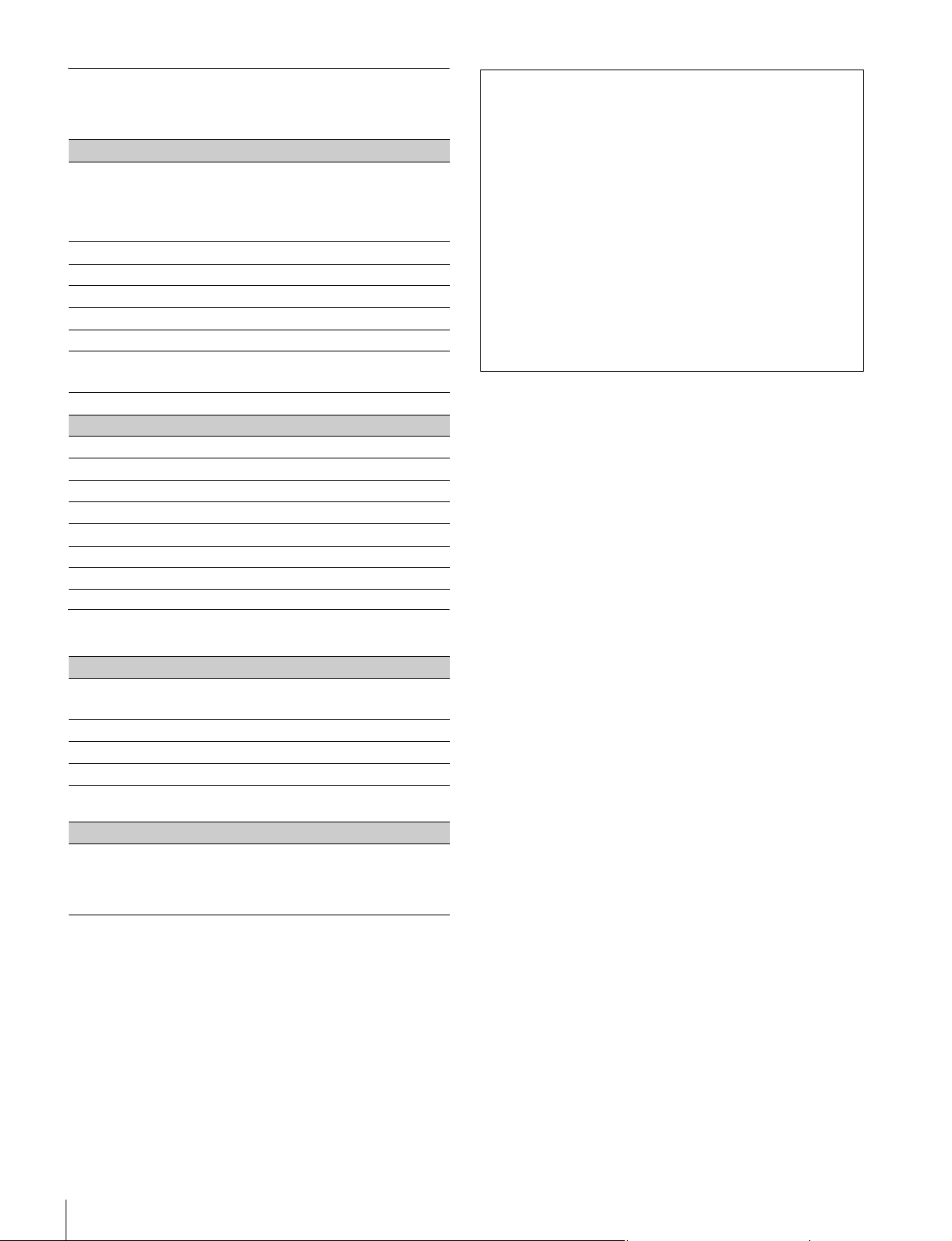
Optional Accessories/Related Equipment
Optional accessories
HD Electronic
Viewfinder
Microphone Holder CAC-12
Return Video Selector CAC-6
Shoulder Adaptor VCT-FSA5
Tripod Attachment VCT-14
Camera Power Boost Kit SKC-PB40
Lens Mount Adaptor LA-FZB1
F65 Adaptor SKC-4065
Related equipment
Digital Motion Picture Camera F65
Solid-state Memory Camcorder PMW-F55
HD Camera Control Unit HDCU2000 series
Remote Control Panel RCP-1000 series
Master Setup Unit MSU-1000 series
Camera Command Network Unit CNU-700
Baseband Processor Unit BPU4000
HDVF-EL75 (7.4-type, color)
DVF-EL100 (0.7-type, color)
DVF-L350 (3.5-type, color)
DVF-L700 (7-type, color)
LA-FZB2
Notes
• Always verify that the unit is operating properly before use.
SONY WILL NOT BE LIABLE FOR DAMAGES OF ANY
KIND INCLUDING, BUT NOT LIMITED TO,
COMPENSATION OR REIMBURSEMENT ON ACCOUNT
OF THE LOSS OF PRESENT OR PROSPECTIVE
PROFITS DUE TO FAILURE OF THIS UNIT, EITHER
DURING THE WARRANTY PERIOD OR AFTER
EXPIRATION OF THE WARRANTY, OR FOR ANY
OTHER REASON WHATSOEVER.
• SONY WILL NOT BE LIABLE FOR CLAIMS OF ANY KIND
MADE BY USERS OF THIS UNIT OR MADE BY THIRD
PARTIES.
• SONY WILL NOT BE LIABLE FOR THE TERMINATION
OR DISCONTINUATION OF ANY SERVICES RELATED
TO THIS UNIT THAT MAY RESULT DUE TO
CIRCUMSTANCES OF ANY KIND.
SKC-PB40
General
Power requirement 240 V AC, 1.7 A (max.)
180 V DC, 1.0 A (max.)
Operating temperature 0 °C to 40 °C (32 °F to 104 °F)
Storage temperature –20 °C to +60 °C (–4 °F to +140 °F)
Mass Approx. 0.7 kg (1 lb 8.7 oz)
Dimensions 112 × 196 × 40 mm
Output connectors
DC OUT XLR 4-pin (2): 14 V, 6.5 A
1
/2 × 7 3/4 × 1 5/8 in.) (W/H/D)
(4
4-pin (1): 24 V DC, 3.7 A
(135 W 3-system maximum output
power)
48
Specifications
Page 49
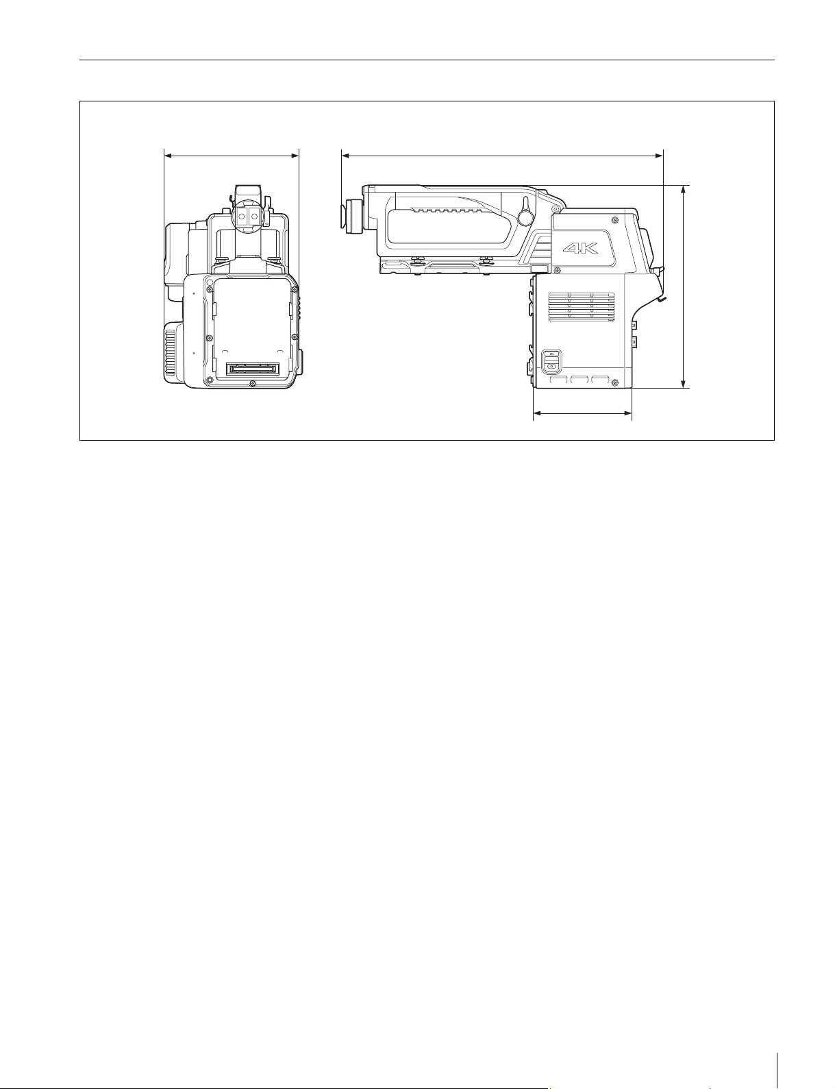
Dimensions
147 (5
Units: mm (inches)
7
/8)
350 (13 7/8)
108 (4
)
4
/
3
221 (8
3
/8)
Specifications
49
Page 50

The material contained in this manual consists of information
that is the property of Sony Corporation and is intended solely
for use by the purchasers of the equipment described in this
manual.
Sony Corporation expressly prohibits the duplication of any
portion of this manual or the use thereof for any purpose other
than the operation or maintenance of the equipment described
in this manual without the express written permission of Sony
Corporation.
Page 51

CA4000 (JN/SY/CE)
4-479-641-12 (1)
Sony Corporation
© 2013
 Loading...