

Sony XR-CA360, CA360X Service Manual
q
XR-CA360/CA360X
Q
Q
3
6
7
SERVICE MANUAL
Ver 1.1 2003.02
TEL 13942296513 QQ 376315150 892498299
3
1
5
1
5
0
Photo: XR-CA360
8
9
2
4
9
8
2
9
9
E Model
XR-CA360/CA360X
Saudi Arabia Model
XR-CA360
Model Name Using Similar Mechanism NEW
Tape T r ansport Mechanism Type MG-36SZ13-32
CA
TEL 13942296513 QQ 376315150 892498299
Cassette player section
Tape track 4-track 2-channel stereo
Wow and flutter 0.13 % (WRMS)
TEL
13942296513
Frequency response 30 – 15,000 Hz
Signal-to-noise ratio 55 dB
Tuner section
FM
Tuning range
(E model)
Tuning range
(Saudi Arabia model)
Aerial terminal External aerial connector
Intermediate frequency 10.7 MHz/450 kHz
Usable sensitivity 9 dBf
Selectivity 75 dB at 400 kHz
Signal-to-noise ratio 67 dB (stereo),
Harmonic distortion at 1 kHz
Separation 35 dB at 1 kHz
uency response 30 – 15,000 Hz
Fre
FM tuning interval:
50 kHz/200 kHz
switchable
87.5 – 108.0 MHz
(at 50 kHz step)
87.5 – 107.9 MHz
(at 200 kHz step)
87.5 – 108.0 MHz
69 dB (mono)
0.5 % (stereo),
0.3 % (mono)
SPECIFICATIONS
AM (E model)
Tuning range AM tuning interval:
Q
Aerial terminal External aerial connector
Intermediate frequency 10.7 MHz/450 kHz
Sensitivity 30 µV
MW/SW (Saudi Arabia model)
Tuning range MW: 531 – 1,602 kHz
Aerial terminal External aerial connector
Intermediate frequency 10.7 MHz/450 kHz
Sensitivity 30 µV
Power amplifier section
Outputs Speaker outputs
Speaker impedance 4 – 8 ohms
Maximum power output 45 W × 4 (at 4 ohms)
9 kHz/10 kHz switchable
531 – 1,602 kHz
7
3
(at 9 kHz step)
Q
530 – 1,710 kHz
(at 10 kHz step)
SW1: 2,940 – 7,735 kHz
SW2: 9,500 – 18,135 kHz
(except for 10,140 – 11,575
kHz)
(sure seal connectors)
6
3
1
General
Outputs Audio output
9
8
0
5
1
5
Inputs BUS control input terminal
Tone controls Low:
Power requirements 12 V DC car battery
Dimensions Approx. 178 × 50 × 178 mm
Mounting dimensions Approx. 182 × 53 × 161 mm
Mass Approx. 1.2 kg
Supplied accessories Parts for installation and
Design and specifications are subject to change
without notice.
Power aerial relay control
9
4
2
lead
Power amplifier control
lead
BUS audio input terminal
±10 dB at 60 Hz (Xplod)
Mid:
±10 dB at 1 kHz (Xplod)
High:
±10 dB at 10 kHz (Xplod)
(negative earth)
(w/h/d)
(w/h/d)
connections (1 set)
Front panel case (1)
8
2
9
9
E model
FM/AM/CASSETTE CAR STEREO
Saudi Arabia model
FM/MW/SW CASSETTE CAR STEREO
w
w
w
9-874-258-02 Sony Corporation
2003B0500-1 e Vehicle Company
C 2003.02 Published by Sony Engineering Corporation
.
xia
o
y
u
1
6
3
.
c
o
m
XR-CA360/CA360X
d
Ver 1.1
TABLE OF CONTENTS
7
Q
Q
SERVICING NOTES............................................... 2
1. GENERAL
Location of Controls ....................................................... 3
Setting the Clock ............................................................. 3
2. DISASSEMBLY
2-1. Disassembly Flow ........................................................... 7
2-2. Sub Panel......................................................................... 7
2-3. Mechanism Deck (MG-36SZ13-32)............................... 8
2-4. MAIN Board ................................................................... 8
2-5. Heat Sink ......................................................................... 9
2-6. Bracket (MD) .................................................................. 9
2-7. DC Motor (Capstan/Reel) (M901) ................................. 10
TEL 13942296513 QQ 376315150 892498299
2-8. Main Belt, Sub Belt (C) .................................................. 10
2-9. Magnetic Head (Playback) (HP901) .............................. 11
3. MECHANICAL ADJUSTMENTS....................... 12
4. ELECTRICAL ADJUSTMENTS......................... 12
Tape Dec k Section .......................................................... 12
Tuner Section .................................................................. 13
5. DIAGRAMS
5-1. Note for Printed Wiring Boards and
Schematic Diagrams ....................................................... 14
5-2. Printed Wiring Board – MAIN Board – ........................ 15
5-3. Schematic Diagram – MAIN Board (1/2) – .................. 16
5-4. Schematic Diagram – MAIN Board (2/2) – .................. 17
5-5. Printed Wiring Board – CONTROL Board – ................ 18
TEL
5-6. Schematic Diagram – CONTROL Board –................... 19
5-7. IC Pin Function Description ........................................... 21
3
13942296513
6
3
1
5
1
5
0
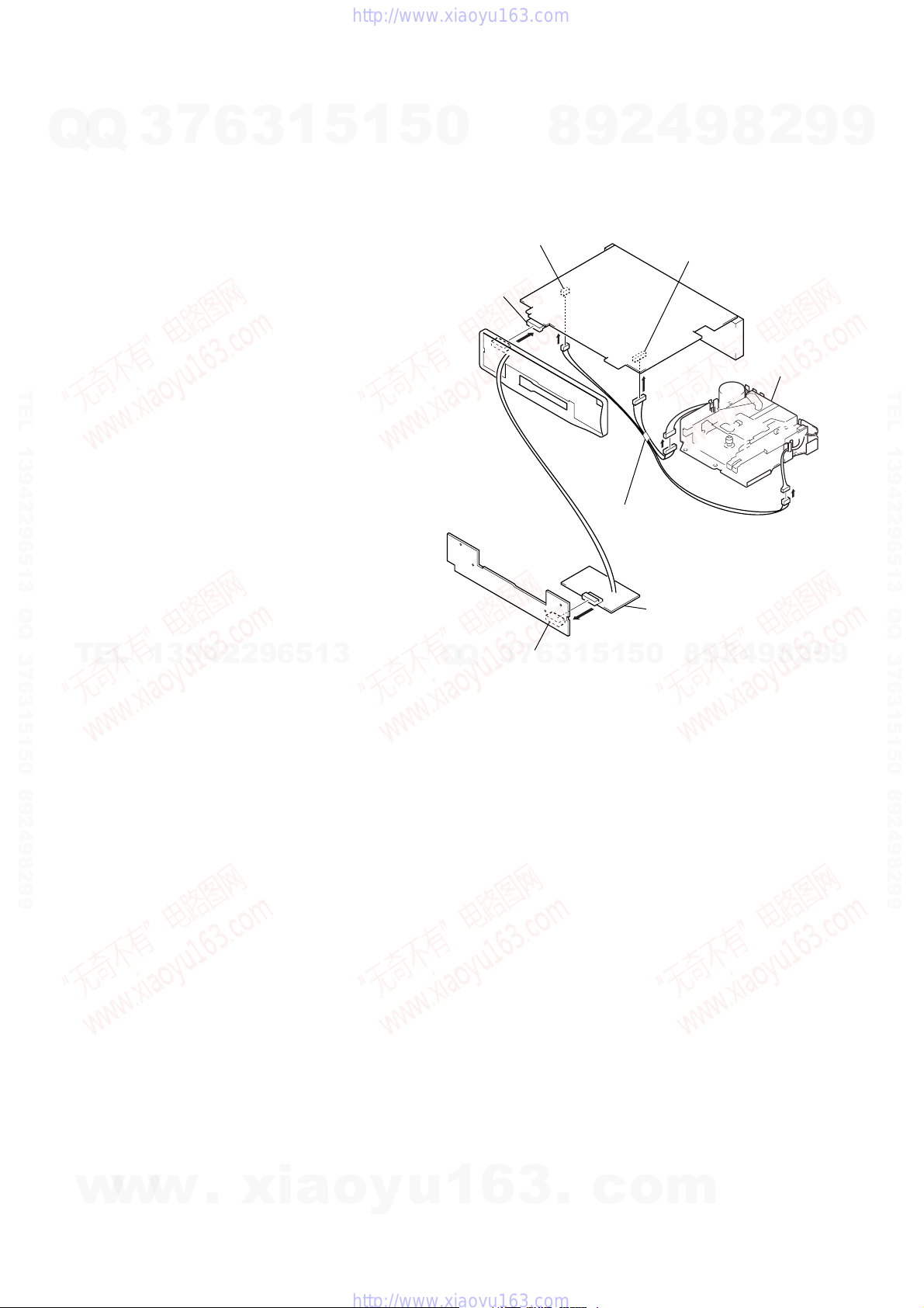
SERVICE POSITION
In checking the control board and main board, prepare two jigs
(extension (MD) cord J-2502-060-1 and
connection cable for F/P to main J-2502-072-1).
main board (CN300)
main board
(CN600)
control board (CN900)
7
3
Q
Q
SERVICING NOTES
2
9
8
connect jig
(extention (MD) cord J-2502-060-1)
to the main board (CN300, CN350)
and mechanism deck.
0
5
1
5
1
3
6
4
9
main board (CN350)
connect jig
(connection cable
for F/P to main J-2502-072-1)
to the main board (CN600) an
control board (CN900).
8
9
2
2
8
mechanism deck
2
8
9
4
9
9
9
TEL 13942296513 QQ 376315150 892498299
9
6. EXPLODED VIEWS
6-1. General Section ............................................................... 23
6-2. Front Panel Section ......................................................... 24
6-3. MAIN Board Section ...................................................... 25
6-4. Mechanism Deck Section (MG-36SZ13-32) ................. 26
7. ELECTRICAL PARTS LIST ............................... 27
Flexible Circuit Board Repairing
•Keep the temperature of the soldering iron around 270 ˚C dur-
ing repairing.
• Do not touch the soldering iron on the same conductor of the
circuit board (within 3 times).
• Be careful not to apply force on the conductor when soldering
or unsoldering.
Notes on chip component replacement
•Never reuse a disconnected chip component.
w
w
w
• Notice that the minus side of a tantalum capacitor may be dam-
aged by heat.
2
.
xia
o
y
u
1
6
3
.
c
o
m
y
play
SECTION 1
GENERAL
XR-CA360/CA360X
This section is extracted from
instruction manual.
7
Q
Q
TEL 13942296513 QQ 376315150 892498299
TEL
3
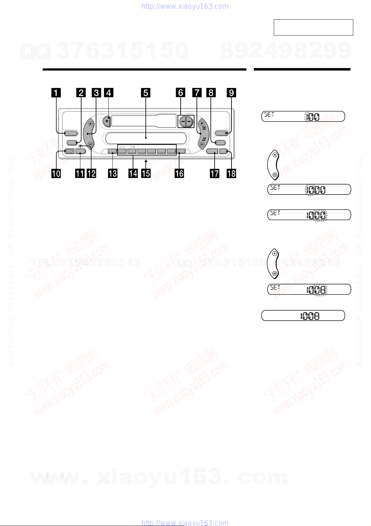
Location of controls
SOURCE
RELEASE
Refer to the pages listed for details.
1 SOURCE (Radio/CD/MD) button
2 MODE button
During radio reception:
Band select
During CD/MD playback:
CD/MD unit select
3 Volume +/– button
4 Z (eject) button
5 Display window
6 m/M (fast winding)/DIR (tape
13942296513
transport direction change) buttons
7 SEEK button
Seek
Automatic Music Sensor
Manual search
8 DSPL (display mode change) button
9 EQ3 button
0 RELEASE (front panel release) button
qa SEL (select) button
qs RESET button (located on the front side
of the unit behind the front panel)
qd ATT (attenuate) button
6
MODE
SEL
3
ATT
1
5
1
5
DISC
123456
SHUF
REP
qf Number buttons
During radio reception:
Preset number select
During CD/MD playback:
(1) DISC –
(2) DISC +
(3) REP
(4) SHUF
qg Frequency select switch (E model)
(located on the bottom of the unit)
See “Frequency select switch” in the
Installation/Connections manual.
qh BTM/ATA button
qj SENS button
qk OFF button*
* Warning when installing in a car
without ACC (accessory) position on
the ignition key switch
Be sure to press (OFF) on the unit for 2
seconds to turn off the clock display after
turning off the engine.
When you press (OFF) momentarily, the
clock display does not turn off and this
causes batter
0
ATA
BTM
XR-CA360X/CA360
Q
Q
wear.
DIR
SEEK
7
3
8
EQ3
DSPL
6
OFFSENS
3
9
1
4
2
Setting the clock
The clock uses a 12-hour digital indication.
Example: To set the clock to 10:08
1
Press (DSPL) for 2 seconds.
The hour indication flashes.
1 Press either side of the volume button
to set the hour.
2 Press (SEL).
The minute indication flashes.
3 Press either side of the volume button
to set the minute.
8
0
5
1
5
2
Press (DSPL).
The clock starts.
After the clock setting is complete, the
dis
8
9
to go forward
to go back
to go forward
4
2
9
to go back
returns to normal play mode.
2
9
8
9
2
9
9
TEL 13942296513 QQ 376315150 892498299
9
w
w
w
.
xia
o
y
u
1
6
3
.
c
o
m
3
XR-CA360/CA360X
2
Q
Q
3
7
6
3
1
5
1
5
0
A
B
TEL 13942296513 QQ 376315150 892498299
*not supplied
no suministrado
BUS AUDIO IN
BUS CONTROL IN
Source selector*
Selector de fuente*
XA-CA30
AUDIO OUT
BUS AUDIO IN
BUS CONTROL IN
REAR
8
9
2
4
9
8
2
9
9
TEL 13942296513 QQ 376315150 892498299
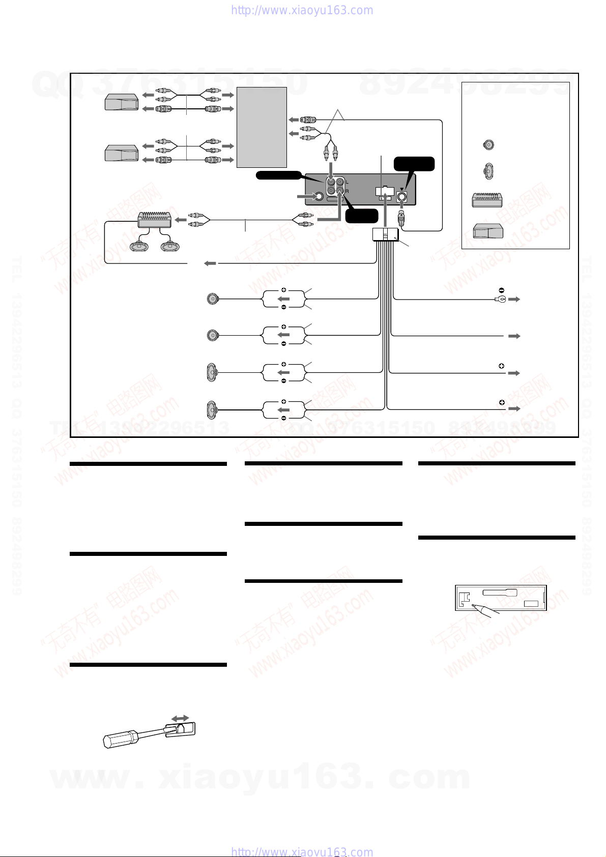
Cautions
TEL
•This unit is designed for negative earth 12 V DC
operation only.
•Do not get the wires under a screw, or caught in
moving parts (e.g. seat railing).
•Before making connections, turn the car ignition
off to avoid short circuits.
•Connect the yellow and red power input leads
only after all other leads have been connected.
•Run all earth wires to a common earth point.
•Be sure to insulate any loose unconnected wires
with electrical tape for safety.
Notes on the power supply cord (yellow)
•When connecting this unit in combination with
other stereo components, the connected car
circuit’s rating must be higher than the sum of
each component’s fuse.
•When no car circuits are rated high enough,
connect the unit directly to the battery.
Parts Iist (1)
•The numbers in the list are keyed to those in the
instructions.
•The bracket 1 and the protection collar 5 are
attached to the unit before shipping. Before
mounting the unit, use the release keys 7 to
remove the bracket 1 and the protection collar
5 from the unit. For details, see “Removing the
protection collar and the bracket (4)” on the
reverse side of the sheet.
•Keep the release keys 7 for future use as they
are also necessary if you remove the unit from
your car.
Caution
Handle the bracket 1 carefully to avoid injuring
your fingers.
13942296513
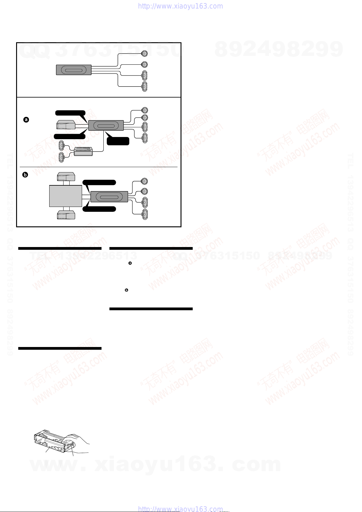
Connection example (2)
Notes (2-B- )
• Be sure to connect the earth cord before connecting
the amplifier.
•If you connect an optional power amplifier and do
not use the built-in amplifier, the beep sound will be
deactivated.
Tip (2-B-
For connecting two or more CD/MD changers, the
source selector XA-C30 (optional) is necessary.
Connection diagram (3)
1 To a metal surface of the car
2 To the power aerial control lead or power supply
3 To AMP REMOTE IN of an optional power amplifier
4 To the +12 V power terminal which is energised in
5 To the +12 V power terminal which is energised at
)
First connect the black earth lead, then connect the
yellow and red power input leads.
lead of aerial booster amplifier
Notes
•It is not necessary to connect this lead if there is no
power aerial or aerial booster, or with a manuallyoperated telescopic aerial.
•When your car has a built-in FM/AM aerial in the
rear/side glass, see “Notes on the control and
power supply leads.”
This connection is only for amplifiers. Connecting
any other system may damage the unit.
the accessory position of the ignition key switch
Notes
•If there is no accessory position, connect to the +12
V power (battery) terminal which is energised at
all times.
Be sure to connect the black ground lead to a
metal surface of the car first.
•When your car has a built-in FM/AM aerial in the
rear/side glass, see “Notes on the control and
power supply leads.”
all times
Be sure to connect the black ground lead to a metal
surface of the car first.
Q
Q
Notes on the control and power supply leads
• The power aerial control lead (blue) supplies +12 V
DC when you turn on the tuner.
7
3
•When your car has built-in FM/AM aerial in the rear/
side glass, connect the power aerial control lead
(blue) or the accessory power input lead (red) to the
power terminal of the existing aerial booster. For
details, consult your dealer.
•A power aerial without relay box cannot be used with
this unit.
Memory hold connection
When the yellow power input lead is connected, power
will always be supplied to the memory circuit even
when the ignition key is turned off.
Notes on speaker connection
• Before connecting the speakers, turn the unit off.
• Use speakers with an impedance of 4 to 8 ohms, and
with adequate power handling capacities to avoid its
damage.
• Do not connect the speaker terminals to the car
chassis, or connect the terminals of the right speakers
with those of the left speaker.
• Do not connect the earth lead of this unit to the
negative (–) terminal of the speaker.
• Do not attempt to connect the speakers in parallel.
• Connect only passive speakers. Connecting active
speakers (with built-in amplifiers) to the speaker
terminals may damage the unit.
• To avoid a malfunction, do not use the built-in
speaker wires installed in your car if the unit shares a
common negative (–) lead for the right and left
speakers.
• Do not connect the unit’s speaker cords to each other.
6
3
1
5
1
5
0
8
9
2
4
9
8
2
9
9
1
Note
Before installing, make sure that the catches on both
sides of the bracket 1 are bent inwards 2 mm. If the
w
catches are straight or bent outwards, the unit will not
be installed securely and may spring out.
4
w
Catch
w
.
xia
o
y
u
1
6
3
.
c
o
m
XR-CA360/CA360X
Q
3
Q
3
6
Supplied with the CD/MD changer
Suministrado con el cambiador de CD/MD
7
TEL 13942296513 QQ 376315150 892498299
TEL
13942296513
3
1
5
1
from car aerial
de antena de automóvil
RCA pin cord (not supplied)
Cable con clavijas RCA (no suministrado)
AMP REM
3
Max. supply current 0.3 A
Corriente máx. de alimentación de 0,3 A
Left
Izquierdo
Right
Derecho
Left
Izquierdo
Right
Derecho
5
Source selector
(not supplied )
Selector de fuente
(no suministrado )
XA-C30
BUS AUDIO IN
0
Q
Q
Supplied with XA-C30
Suministrado con el XA-C30
BUS
AUDIO
AUDIO IN
OUT
OUT REAR
Blue/white striped
Con raya azul/blanca
White
Blanco
White/black striped
Con raya blanca/negra
Grey
Gris
Grey/black striped
Con raya gris/negra
Green
Verde
Green/black striped
Con raya verde/negra
Purple
Púrpura
Purple/black striped
Con raya violeta/negra
7
3
8
AUDIO
3
6
9
Fuse (10 A)
Fusible (10 A)
5
1
4
2
BUS
CONTROL IN
6
Black
Negro
Blue
Azul
Corriente máx. de alimentación de 0,1 A
Red
Rojo
Yellow
Amarillo
0
5
1
9
Max. supply current 0.1 A
8
Equipment used in illustrations
(not supplied)
Equipo utilizado en las ilustraciones
(no suministrado)
2
9
8
ANT REM
4
2
9
Front speaker
Altavoces delanteros
Rear speaker
Altavoces traseros
Power amplifier
Amplificador de potencia
CD/MD
Cambiador de CD/MD
1
2
4
5
2
8
9
9
9
TEL 13942296513 QQ 376315150 892498299
9
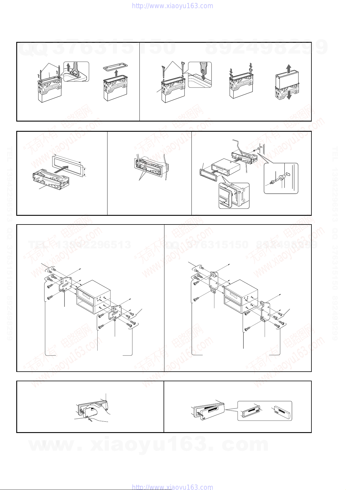
Precautions
•Choose the installation location carefully so that the unit will not
interfere with normal driving operations.
•Avoid installing the unit in areas subject to dust, dirt, excessive
vibration, or high temperatures, such as in direct sunlight or near
heater ducts.
•Use only the supplied mounting hardware for a safe and secure
installation.
Mounting angle adjustment
Adjust the mounting angle to less than 20°.
Removing the protection collar and the
bracket (4)
Before installing the unit, remove the protection collar 5 and
the bracket 1 from the unit.
1
Remove the protection collar 5.
1 Engage the release keys 7 together with the protection collar
5 .
2 Pull out the release keys 7 to remove the protection collar 5.
2
Remove the bracket 1.
1 Insert both release keys 7 together between the unit and the
bracket until they click.
2 Pull down the bracket 1, then pull up the unit to separate.
Frequency select switch (E model)
The AM (FM) tuning interval is factory-set to the 9 k (50 k) position.
If the frequency allocation system of your country is based on 10 kHz
(200 kHz) interval, set the switch on the bottom of the unit to the 10 k
(200 k) position before making connections.
Mounting example (5)
Installation in the dashboard
Notes
• Bend these claws outward for a tight fit, if necessary (5-2).
•Make sure that the 4 catches on the protection collar 5 are properly
engaged in the slots of the unit (5-3).
Mounting the unit in a Japanese car (6)
You may not be able to install this unit in some makes of Japanese
cars. In such a case, consult your Sony dealer.
Note
To prevent malfunction, install only with the supplied screws 4.
How to detach and attach the front panel
(7)
Before installing the unit, detach the front panel.
7-A To detach
Before detaching the front panel, be sure to press (OFF).
Press (RELEASE), then slide the front panel to the left, and pull it off
towards you.
7-B To attach
Attach part A of the front panel to part B of the unit as illustrated
and push the left side into position until it clicks.
Warning when installing in a car without ACC
(accessory) position on the ignition key
switch
Be sure to press (OFF) on the unit for two seconds to turn
off the clock display after turning off the engine.
When you press (OFF) only momentarily, the clock display does not
turn off and this causes battery wear.
RESET button
When the installation and connections are completed, be sure to
press the RESET button with a ballpoint pen, etc., after detaching the
front panel.
w
w
w
.
xia
o
y
u
1
6
3
.
c
o
m
5
XR-CA360/CA360X
1
4
Q
Q
7
5
1
5
TEL 13942296513 QQ 376315150 892498299
1
7
3
Orient the release key
correctly.
Oriente la llave de
liberación en la dirección
correcta.
182 mm
6
53 mm
3
c
1
2
5
1
Claws
Uñas
2
5
1
0
7
Face the hook inwards.
El gancho debe
encontrarse en la parte
interior.
3
8
5
9
c
Dashboard
Salpicadero
1
2
4
9
c
8
Fire wall
Panel cortafuegos
2
3
2
9
9
TEL 13942296513 QQ 376315150 892498299
A
6
TOYOTA NISSAN
TEL
4
max. size
5 × 8 mm
Tamaño máx.
5 × 8mm
AB
7
13942296513
to dashboard/centre console
al salpicadero/consola central
Bracket
Soporte
Bracket
Soporte
Existing parts supplied with your car
Piezas existentes suministradas con su automóvil
(OFF)
4
max. size
5 × 8 mm
Tamaño máx.
5 × 8mm
B
Q
Q
max. size
5 × 8 mm
Tamaño máx.
5 × 8mm
4
3
1
3
6
7
Bracket
Soporte
Existing parts supplied with your car
Piezas existentes suministradas con su automóvil
5
1
5
0
9
4
2
9
8
to dashboard/centre console
al salpicadero/consola central
Bracket
Soporte
2
8
4
max. size
5 × 8 mm
Tamaño máx.
5 × 8mm
9
9
6
w
w
(RELEASE)
w
.
xia
o
y
u
1
6
3
.
c
o
B
m
A
Q
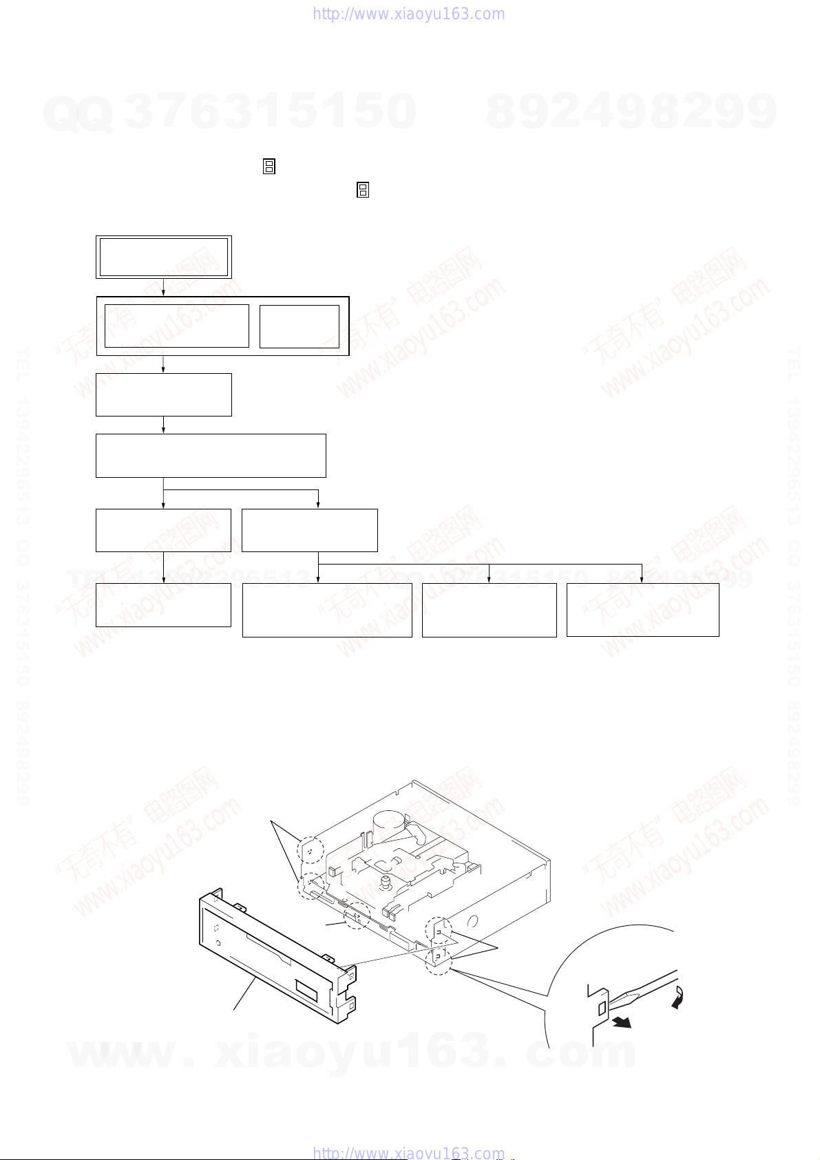
SECTION 2
DISASSEMBLY
• This set can be disassembled in the order shown below.
7
Q
3
2-1. DISASSEMBLY FLOW
Note 1: The process described in can be performed in any order.
Note 2: Without completing the process described in , the next process can not be performed.
Note 3: Illustration of disassembly is omitted.
6
SET
3
1
5
1
5
0
8
9
2
XR-CA360/CA360X
4
9
8
2
9
9
FRONT PANEL SECTION
TEL 13942296513 QQ 376315150 892498299
2-2. SUB PANEL
2-3. MECHANISM DECK (MG-36SZ13-32)
2-4. MAIN BOARD
TEL
2-5. HEAT SINK
Note: Follow the disassembly procedure in the numerical order given.
2-2. SUB PANEL
(Note 3)
(Page 7)
(Page 8)
(Page 8)
13942296513
(Page 9)
COVER
(Note 3)
2-6. BRACKET (MD)
(Page 9)
2-7. DC MOTOR
(CAPSTAN/REEL) (M901)
(Page 10)
Q
3
Q
2-8. MAIN BELT,
7
SUB BELT (C)
(Page 10)
6
3
1
5
9
8
0
5
1
2-9. MAGNETIC HEAD
(PLAYBACK) (HP901)
(Page 11)
2
4
9
8
2
9
TEL 13942296513 QQ 376315150 892498299
9
w
w
w
.
xia
1
2
sub panel
two claws
1
claw
o
y
u
1
6
3
1
.
two claws
c
o
m
7
XR-CA360/CA360X
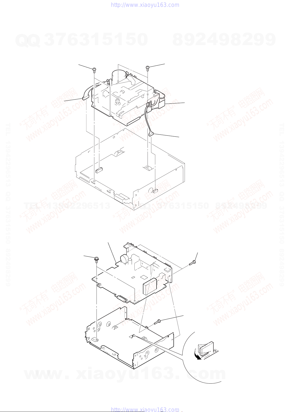
2-3. MECHANISM DECK (MG-36SZ13-32)
Q
Q
3
1
connector
(CN350)
7
2
two screws
(PTT2.6
6
×
6)
3
1
5
1
5
0
8
2
two screws
(PTT2.6
2
9
×
6)
3
mechanism deck (MG-36SZ13-32)
4
9
8
2
9
9
TEL 13942296513 QQ 376315150 892498299
TEL
2-4. MAIN BOARD
13942296513
2
two ground point screws
(PTT2.6
×
6)
4
main board
Q
Q
3
7
6
3
1
1
5
connector
(CN300)
5
1
3
8
0
two screws
(PTT2.6
TEL 13942296513 QQ 376315150 892498299
9
9
2
8
9
4
2
9
×
6)
8
w
w
w
.
xia
o
y
u
1
6
3
.
3
c
screw
(PTT2.6
1
o
×
6)
claw
m

)
Q
2-5. HEAT SINK
7
Q
3
6
3
1
5
1
5
0
2
heat sink
8
9
2
1
4
9
two screws
(PTT2.6
×
XR-CA360/CA360X
10)
8
2
9
9
TEL 13942296513 QQ 376315150 892498299
TEL
13942296513
2-6. BRACKET (MD)
Q
Q
3
7
6
3
1
5
1
5
0
1
five screws
(PTT2.6
9
8
2
4
TEL 13942296513 QQ 376315150 892498299
×
10
9
9
2
8
9
w
w
w
1
claw
.
xia
3
bracket (MD)
o
y
u
1
2
6
3
four screws
(B2.6
×
4)
1
claw
.
c
o
m
1
claw
9
XR-CA360/CA360X
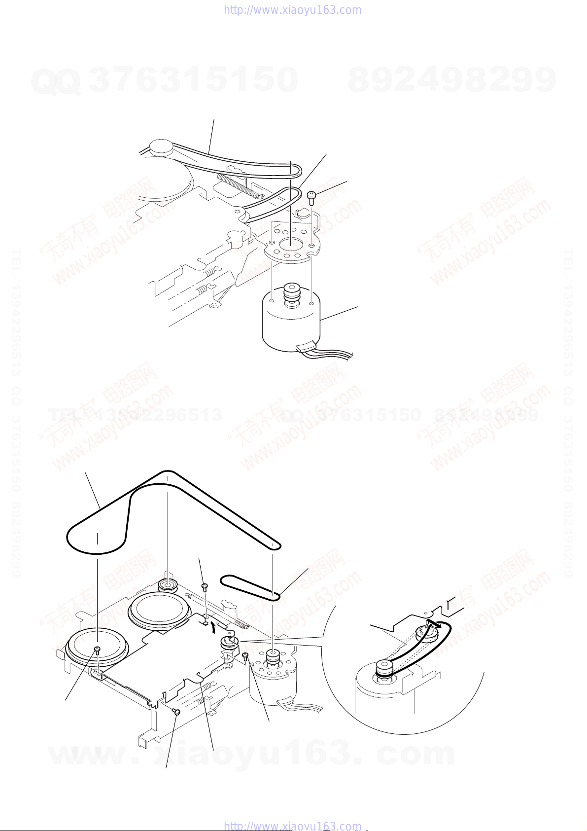
2-7. DC MOTOR (CAPSTAN/REEL) (M901)
Q
Q
3
7
6
3
1
5
2
main belt
1
5
0
8
3
sub belt (C)
1
two screws
(P2
9
×
2.5)
2
4
9
8
2
9
9
TEL 13942296513 QQ 376315150 892498299
TEL
2-8. MAIN BELT, SUB BELT (C)
1
13942296513
main belt
Q
Q
3
7
4
DC motor (capstan/reel) (M901)
Note :When installing motor,
adjust the screw and
screw hole of motor.
5
1
5
1
3
6
0
8
9
2
4
9
8
2
9
TEL 13942296513 QQ 376315150 892498299
9
10
2
screw
(PTP2
w
w
×
3)
w
.
xia
2
screw
(PTP2
2
×
3)
screw
(PTP2
A
×
3)
4
sub belt (c)
2
screw
(PTP2
×
3)
3
Lift up the bottom BKT (TS)
o
y
u
1
6
in the direction of arrow
(as far as the belt can be removed).
A
3
.
c
o
m
9
screw
(P2
×
4)
5
screw
(PTP2
×
3)
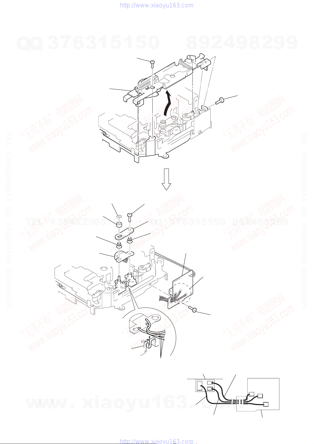
qd
Remove three magnetic
head lead wires from
the adjuster arm blue.
magnetic head
(HP901)
magnetic head lead wire
adjuster arm blue
•MAGNETIC HEAD LEAD WIRE COLOR INDICATION
ON HEAD (HP901) AND SLIDE SW BOARD.
0
SPG support plate
7
PSW (reel) B
8
HP roller (A)
qa
adjuster arm SPG (A)
qs
adjuster arm SPG (B)
qf
magnetic head (play back) (HP901)
6
slide SW board
4
Remove the three solders
of magnetic head lead wires.
yellow lead wire
black lead wire
red lead wire
slide SW board
Q
2-9. MAGNETIC HEAD (PLAYBACK) (HP901)
Q
3
7
6
3
FF/REV lever section
3
1
5
2
screw
(PTT2
1
×
4)
5
0
8
9
2
XR-CA360/CA360X
4
9
1
8
screw
(P2
×
2
3)
9
9
TEL 13942296513 QQ 376315150 892498299
TEL
13942296513
Q
Q
3
7
6
3
1
5
1
5
0
8
9
2
4
9
8
2
9
TEL 13942296513 QQ 376315150 892498299
9
w
w
w
.
xia
o
y
u
1
6
3
.
c
o
m
11
 Loading...