

Page 1

C9000 Series
Color LED Page Printer
Service Manual
ODA
05-18-200 Based on Rev.2
41388601TH Rev.2A 1 / 157
Page 2
Document Revision History
3 05-18-2001 ODA Revisions ODA Training
Rev.No. Date
No.
Corrected items
Page Description of change
Person in
charge
1 2000-12-05 ISSUE EM3 Murakami
2 2000-12-13 8 Correction of errors in K Yamazaki
the parts list
41388601TH Rev.2A 2 /
Page 3

PREFACE
This maintenance manual provides procedures and techniques for the troubleshooting, maintenance, and
repair of C9000.
This manual is written for maintenance personnel, but it should always be accompanied with the C9000
User’s Manual for procedures for handling and operating C9000. For repairing each component of C9000,
see the Troubleshooting manual.
[Notices]
The contents of this manual are subject to change without prior notice.
Although reasonable efforts have been taken in the preparation of this manual to assure its accuracy, this
manual may still contain some errors and omissions. OKI will not be liable for any damage caused or
alleged to be caused, by the customer or any other person using this maintenance manual to repair,
modify, or alter C9000 in any manner.
[Warning]
Many parts of C9000 are very sensitive and can be easily damaged by improper servicing. We strongly
suggest that C9000 be serviced by OKI’s authorized technical service engineers.
41388601TH Rev.2 3 /
Page 4

CONTENTS
1. SPECIFICATIONS ............................................................................................ 7
1.1 Basic System Configuration............................................................................................. 7
1.2 Printer Engine Specifications ........................................................................................... 8
1.3 Option Configuration ........................................................................................................ 9
1.4 Specifications................................................................................................................. 10
2. OPERATION DESCRIPTION ......................................................................... 12
2.1 Main Control Board (CRM-PWB) ................................................................................... 13
2.2 Engine Control Board (K73 PWB).................................................................................. 15
2.3 Power Units.................................................................................................................... 16
2.4 Mechanical Processes ................................................................................................... 17
2.4.1 Electrophotographic process............................................................................ 18
2.4.2 Paper running process ..................................................................................... 22
2.5 Sensor............................................................................................................................ 31
2.5.1 Paper related sensors ...................................................................................... 31
2.5.2 Other sensors................................................................................................... 32
2.6 Color Misalignment Correction....................................................................................... 33
2.7 Transfer Control Responds to Environmental Changes
(Room Temperatures and Relative Humidities)............................................................. 33
2.8 Paper Jam Detection ..................................................................................................... 34
2.9 Cover Opening............................................................................................................... 35
2.10 Toner Low Detection...................................................................................................... 36
2.11 Paper Size Detection ..................................................................................................... 37
2.12 Operation at Power-on................................................................................................... 38
2.12.1 Self-diagnostic test........................................................................................... 38
2.13 Color Misalignment Detection ........................................................................................ 39
2.14 Version Read of Periodically Replaced Units ................................................................ 40
2.15 Life Counter for Replaceable Units ................................................................................ 40
2.16 Toner Consumption Detection ....................................................................................... 40
3. PARTS REPLACEMENT................................................................................41
3.1 Precautions in Replacing Parts...................................................................................... 41
3.2 Parts Layout................................................................................................................... 43
3.3 Replacing Parts..............................................................................................................50
3.3.1 Top cover.......................................................................................................... 51
3.3.2 LED Assy/ LED Assy spring ............................................................................. 52
3.3.3 Top cover unit................................................................................................... 53
3.3.4 Control panel Assy/ Control panel bezel/ LED control PWB/ Toner sensor/
Stack full sensor/ Control panel tape harness/ Eject roller............................... 54
3.3.5 Top cover handle/ Tope cover latch/ Top cover latch spring............................ 55
3.3.6 Eject guide Assy ............................................................................................... 56
3.3.7 Cassette Assy/ Blind cover/ Side cover R Assy ............................................... 57
3.3.8 Feed rollers....................................................................................................... 58
3.3.9 Left side cover .................................................................................................. 59
3.3.10 Face-up tray ..................................................................................................... 60
3.3.11 Front cover ....................................................................................................... 61
3.3.12 Rear cover........................................................................................................ 62
3.3.13 Multipurpose tray Assy/ Multipurpose tray cover Assy/ Links/
Multipurpose tray top cover/ Multipurpose tray drive gear................................ 63
3.3.14 Drum contact Assys.......................................................................................... 64
3.3.15 Registration roller Assy (A)/ Registration drive gear (A)................................... 65
41388601TH Rev.2 4 /
Page 5

3.3.16 Registration roller Assy (B)............................................................................... 66
3.3.17 Registration clutch, Registration motor Assy.................................................... 67
3.3.18 Cooling fan ....................................................................................................... 68
3.3.19 Color registration sensor Assy.......................................................................... 69
3.3.20 Duplex guide Assy............................................................................................ 70
3.3.21 Electrical chassis/ Electrical chassis cooling fan.............................................. 71
3.3.22 Printer engine controller PWB .......................................................................... 72
3.3.23 Printer unit chassis........................................................................................... 73
3.3.24 Entrance cassette sensor actuator................................................................... 74
3.3.25 Entrance sensor PWB ...................................................................................... 75
3.3.26 Entrance MT sensor actuator and Entrance belt sensor actuator.................... 76
3.3.27 Main motor fan/ Fuser eject roller..................................................................... 77
3.3.28 Eject sensor Assy............................................................................................. 78
3.3.29 Fuser latching handle (L).................................................................................. 79
3.3.30 Belt motor Assy ................................................................................................ 80
3.3.31 Fuser latching handle (R)................................................................................. 81
3.3.32 Main motor Assy............................................................................................... 82
3.3.33 Contact Assy/ Side plate Assy.......................................................................... 83
3.3.34 Low voltage power supply ................................................................................ 84
3.3.35 High voltage power supply ............................................................................... 85
3.3.36 Main feed Assy................................................................................................. 86
3.3.37 Fuser unit.......................................................................................................... 87
3.3.38 Belt unit............................................................................................................. 88
3.3.39 Duplex unit........................................................................................................ 89
3.3.40 CU Assy............................................................................................................ 90
4. Adjustment .................................................................................................... 92
4.1 Maintenance Menu and Its Functions ............................................................................ 92
4.2 Short Plug Settings ........................................................................................................ 93
4.3 Printing Singly Using Controller-Equipped Printer ......................................................... 93
4.4 Adjustment after Part Replacement ............................................................................... 94
4.5 Color Balance Adjustment ............................................................................................. 95
4.6 EEPROM Replacement after CRM Board and K73 Board Replacement ...................... 97
5. Regular Maintenance ....................................................................................98
5.1 Parts to be Replaced Regularly ..................................................................................... 98
5.2 Cleaning......................................................................................................................... 98
5.3 Cleaning of LED Lens Array .......................................................................................... 98
5.4 Cleaning of Pick-up Roller ............................................................................................. 98
6. TROUBLESHOOTING PROCEDURES .........................................................99
6.1 Tips for Troubleshooting ................................................................................................ 99
6.2 Check Points before Correcting Image Problems.......................................................... 99
6.3 Tips for Correcting Image Problems .............................................................................. 99
6.4 Preparation for Troubleshooting .................................................................................. 100
6.5 Troubleshooting Flow................................................................................................... 100
6.5.1 LCD Message List .......................................................................................... 101
6.5.2 LCD message troubleshooting ....................................................................... 106
6.5.3 Image troubleshooting.................................................................................... 117
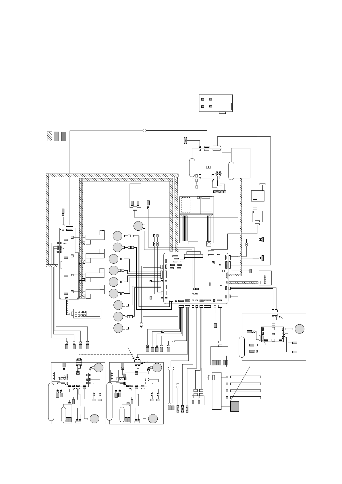
7. WIRING DIAGRAM...................................................................................... 129
7.1 Resistance Check ........................................................................................................ 129
7.2 Parts Layout on Boards ............................................................................................... 134
8. Parts List...................................................................................................... 138
41388601TH Rev.2 5 /
Page 6
Job
offset
M
M
M
M
M
M
M
LED Head
Junction Board
Pulse Motors
Engine Controller
Low-Voltage
Power Unit
Fuser Unit
High-Voltage
Power Unit
2nd/3rd T r ay/
Large-Capacity
Tray
Duplex Unit
Belt Unit
<Sensors, Switches and Thermistors>
Paper carrier sensors
Paper size detection
Fuser temperature detection
Ambient temperature and humidity detection
Toner remaining detection
Color registration sensor
ID, belt and fuser checks
C-ID
Unit
M-ID
Unit
Y-ID
Unit
K-ID
Unit
C ID
M
Heater
M ID
Y ID
K ID
Belt
MT/
Registration
Hopping
Geared
motor
DC motor
Operator Panel
Centronics
USB
IDE
HDD
DC
FAN
Ethernet
ROM DIMM × 3
SDRAM DIMM
× 4
Controller
Block
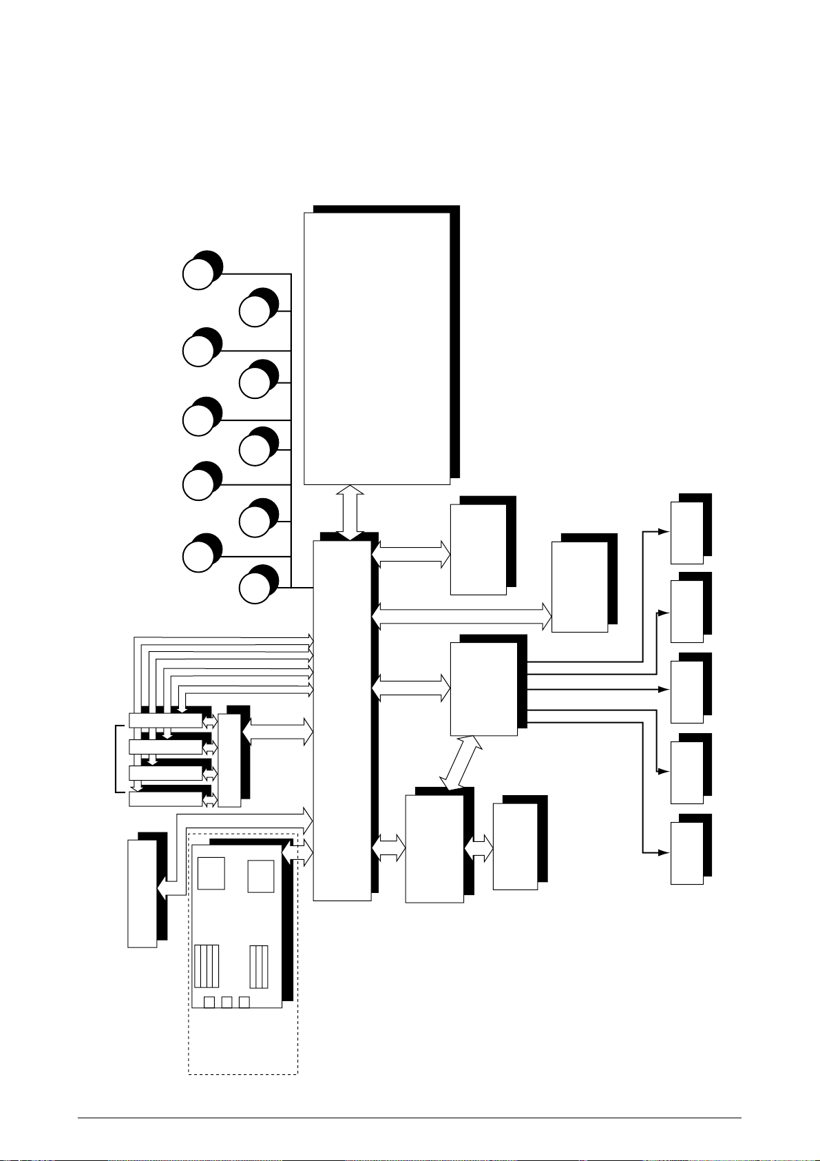
1. SPECIFICATIONS
1.1 Basic System Configuration
The basic system configuration of C9000 is illustrated in Figure 1.1.
Figure 1.1
41388601TH Rev.2 6 /
Page 7
1.2 Printer Engine Specifications
The inside of the printer is composed of the followings:
• Electrophotographic Processor
• Paper Paths
• Controller Block (CU and PU)
• Operator Panel
• Power Units (High-Voltage Unit and Low-Voltage Unit)
Figure 1-2 shows the printer configuration.
Figure 1.2
41388601TH Rev.2 7 /
Page 8

1.3 Option Configuration
The followings are available as options on C9000.
(1) 2nd Tray/ 3rd Tray
(2) Duplex Unit
(3) Large-Capacity Tray
(4) Expansion Memory 64/128/256MB
(5) Internal Hard Disk
(6) Ethernet Board
41388601TH Rev. 2 8 /
Page 9

1.4 Specifications
(1) Dimensions Height: 18.11 in. Width: 26.22 in. Length: 24.65 in.
(2) Weight 158.7 lbs.
(3) Paper Type: Ordinary paper and transparencies (Recommended: ML OHP01)
(4) Print Speed Color: 21 pages per minute (Transparency: 5 pages per minute)
(5) Resolution 600 × 600 DPI / 600 x 1200 DPI (C9200 series) & 1200 x 1200 DPI (C9400 series)
(6) Power Input 100VAC ±10%
(7) Power Consumption Peak: 1400W Normal Operation: 550W (5% duty)
Size: Postal card, Legal 13" or 14", Executive, A4, A5, B5, A6, A3 A3-Nobi, B4
(Only the 1st tray and the front feeder support A6 and postal card
sizes.)
Weight: 1st tray 55 kg to 90 kg (64 to 105g/m
2
)
Front feeder 55 kg to 140 kg (64 to 163g/ m2)
Monochrome: 26 pages per minute (Transparency: 15 pages per minute)
Postal Card, Label, Thick Paper: 10 pages per minute
Idle: 150W Power Saving Mode: 50W
(8) Frequency 50Hz or 60Hz ± 2%
(9) Noise Operating: 54 dB (without Second tray)
Standby: 45 dB
Power Saving: 43 dB
(10) Consumable Life Toner Cartridge: 15,000 pages (5% duty)
(in each of Y, M, C and K)
Image Drum: 39,000 pages (5% duty, Continuous printing)
(in each of Y, M, C and K)
(11) Parts Replaced Periodically Fuser Unit Assy: Every 80,000 pages
Belt Cassette Assy: Equivalent of 80,000 pages (3P/J)
Transfer Belt cartridge: 60,000 prints
41388601TH Rev.2 9 /
Page 10

(12) Temperatures and Relative Humidities
Temperature
Temperature (ºF) RemarkTemperature (ºC)
Operating 50 to 89.6 10 to 32
Non-Operating 32 to 109.4 0 to 43 Power-off
Storage (Max. One Year) -14 to 109.4 -10 to 43 With drum and toner
Transport (Max. One Month) -20 to 122 -29 to 50 With drum and without toner
Transport (Max. One Month) -20 to 122 -29 to 50 With drum and toner
17 to 27ºC (Temperatures to
assure full color print quality)
Humidity
Relative Humidity (%) Max. Wet-Bulb Temperature (ºC) Remark
Operating 20 to 80 25 50 to 70%
(Humidities to assure full color print quality)
Non-Operating 10 to 90 26.8 Power-off
Storage 10 to 90 35
Transport 10 to 90 40
(13 Printer Life 1,000,000 pages (on a A4 basis) or five years
41388601TH Rev.2 10 /
Page 11
Stacker Open
Microswitch
SUMI Card
Sensor/Microswitch
New C9000 Connector
Backup Roller
Thermistor
L-Side Color Registration Adjustment
AOUT3
R-Side Color Registration Adjustment
AOUT2
Eject Sensor Heater
Shutter Clutch
SHUTTER
Regist
Clutch
R
SNS
PO
WER
C
UIFPSIZE
HV
OLT
JO
DEN
FS
ENS
TR
1OP
P5
P6
R
EG
BEL
THETDUPLEX
K73 Main Board
CP
UFL
PAR
TTEMP
SHU
TTER
DCLFC
OVER
DU
COV
PE
NDF
O
HP1
FF
POS
PA
PWID
M7L Board
M7R Board
F
AN1
F
AN2
FF/
Registration
Motor
CO
VOPN
Right Side Cover
Open Microswitch
Upper Cover
Open Microswitch
(+38V cut)
S
W1
Y71 Head
Relay Board
TNRK
TNRY
STUCK POWER
PANEL
MPOW2
CPOW2
YPOW2
KPOW2
TNRM
TNRC
Stacker Full Sensor
Geared
Motor
Loading Clutch
Pickup Clutch
Carrier Sensor
Paper Width Sensor
Offset
Motor
Hopping
Motor
Offset Zero Sensor
C73
I/F Board
Finisher
A73 Retard Sensor Board
Lifter Sensor
Loading Sensor
Belt
Fuse
I DPOSK
I DPOSY
I DPOSM
I DPOSC
N71 Board
(charge elimination relay)
IDC
IDM
IDY
ID
D2 Green
D2 Yellow
K
NBLT
4 x P73 Boards
AC
Input
AC
Input
Fan 3 (off-the-shelf)
Fan 2 (power eject)
Fan 1 (PU)
works as stepper
PEND
PNEND
Offset PE Sensor
Offset Sensor
STDUCOV
JO
BOFF
OPTN
KPOW
K12 00
Y12 00
M120 0
MPOW
YPOW
ID
R
CL
HO
PFF
FR
PUCL
C1200
CPOW
F
ACE
K
L
E
D
H
E
A
D
L
E
D
H
E
A
D
L
E
D
H
E
A
D
L
E
D
H
E
A
D
Y
M
C
F
EED
PAPSIZ3-0
aVR
Paper Width
Sensing Board
HOP
LIFT
MAIL
HOP(I
NSNS1)
H
UM
T
EMP
R71
Board
PAPIN(
INSNS2)
PSWR(
WRSNS)
TN
RFUL
GE
ARED
K IDU
Motor
JOB
OFFS
JOB
OFFPE
connected to next tray
(no tray in lowest section)
connected to trays of up to 5th,
including 2nd tray
(does not exist in the lowest)
2nd T ray/3rd Tray
Large-Capacity T ray
Geared
Motor
Loading
Carrier Clutch
(does not exist
in the lowest)
Loading Clutch
V73 Board
Paper End
Paper Near
End
Cover Opem SW
Carrier Sensor
Paper Width
Sensing Board
T9 Blue
T3 White
T4 Red
T5 Red
T8 Red
T2 Blue
T6
Yellow
Lifter Sensor
Loading Sensor
Retard Sensor
Board A73
T2 White
T1 Blue
T1 White
T7 White
T11
(does not exist
in the lowest)
DUP-In Sensor
DUP Middle Sensor
DUP Front Sensor
DUP
DUP Front Clutch DUP Rear Clutch
D3 Blue
V73 Board
Duplex
D1 Blue
D1 White
Belt
Motor
P1 Yellow
P1 White
P2
P2 Yellow
P3 White
P2 Blue
P2 Red
P4
P4 Red
P4 Yellow
P4 Blue/
White
P6 Brown
P7 Blue
P7 Gray
P7
P8
P7 Gray
attached to
sensor
P9
P9 Black
P10P10
P10 Brown
P11
P11 Blue
P11 White
P21P21
P22
P12P12
P12 Yellow
P13
P13 Red
P14
P14 Yellow
P14 Red
P15 Red
P16 Browm
P17 Red
attached to motor
P16
P5 Red
P18 Black
P19
P18
P17
P20
P18 Yellow
P18 Red
P18 Blue
attached
to clutch
P19 White
P1
P19 Red
P20 White
P20 Yellow
P24 to P31
P23
Y1 White
Y2 Blue
Y1 White
S1 Gray
Heater Unit
Heat Roller
Thermistor
Sensor
Fuse
TH
ERM1
TH
ERM2
NFULH
RTMP
LB
RTMP
C
N8
C
N9
C
N2
C
N1
High-Voltage
Power Supply
C
N5
CN4-
2,6-2
CN4-
1,6-1
AC
SW
S1
Low-Voltage
Power Supply
attached to fan
attached to fan
*1
attached to fan
attached to fan
attached to fan
Heat
Motor
FD
WPAP
Jam Sensor
P2 White
P4 Green
Fan 0 (power-on)
Face-Down Solenoid
Eject Solenoid
Removed-Edge Side
Removed-
Edge Side
P33 White
P33 Blue
Temperature Sensor
P33 Green
Fan 0 (power eject)
DUP_PAP
T6
Blue
White
connected to next tray
(no tray in lowest section)
Geared
Motor
Loading
Carrier Clutch
Loading Clutch
V73 Board
Paper End
Paper Near
End
Cover Opem SW
Carrier Sensor
Paper Width
Sensing Board
T9 Blue
T3 White
T4 Red
T5 Red
T8 Red
T2 Blue
T6
Yellow
Lifter Sensor
Loading Sensor
Retard Sensor
Board A73
T2 White
T10 Red
T1 Blue
T1 White
T7 White
T11
*1
T6
Blue
White
Black
Removed-
Edge Side
White
Black
DUP Rear Sensor
Y6
Y5
Y3
Y4
P24 to P31
Y IDU
Motor
M IDU
Motor
C IDU
Motor
Motor
P17 Yellow
S2
Black
Black
Black
Y4 Green
Y3 Yellow
Y3 Red
Y5 Blown
X71 Board
P24
P28
P25
P29
P26
P30
P27
P31
Operator
Panel
C Charge Elimination Lamp Fuse
M Charge Elimination Lamp Fuse
Y Charge Elimination Lamp Fuse
K Charge Elimination Lamp Fuse
P27
ACSW
Assy
FAN
RAM
CRM Board
ROM
HDD
LAN
USB
CENTRO
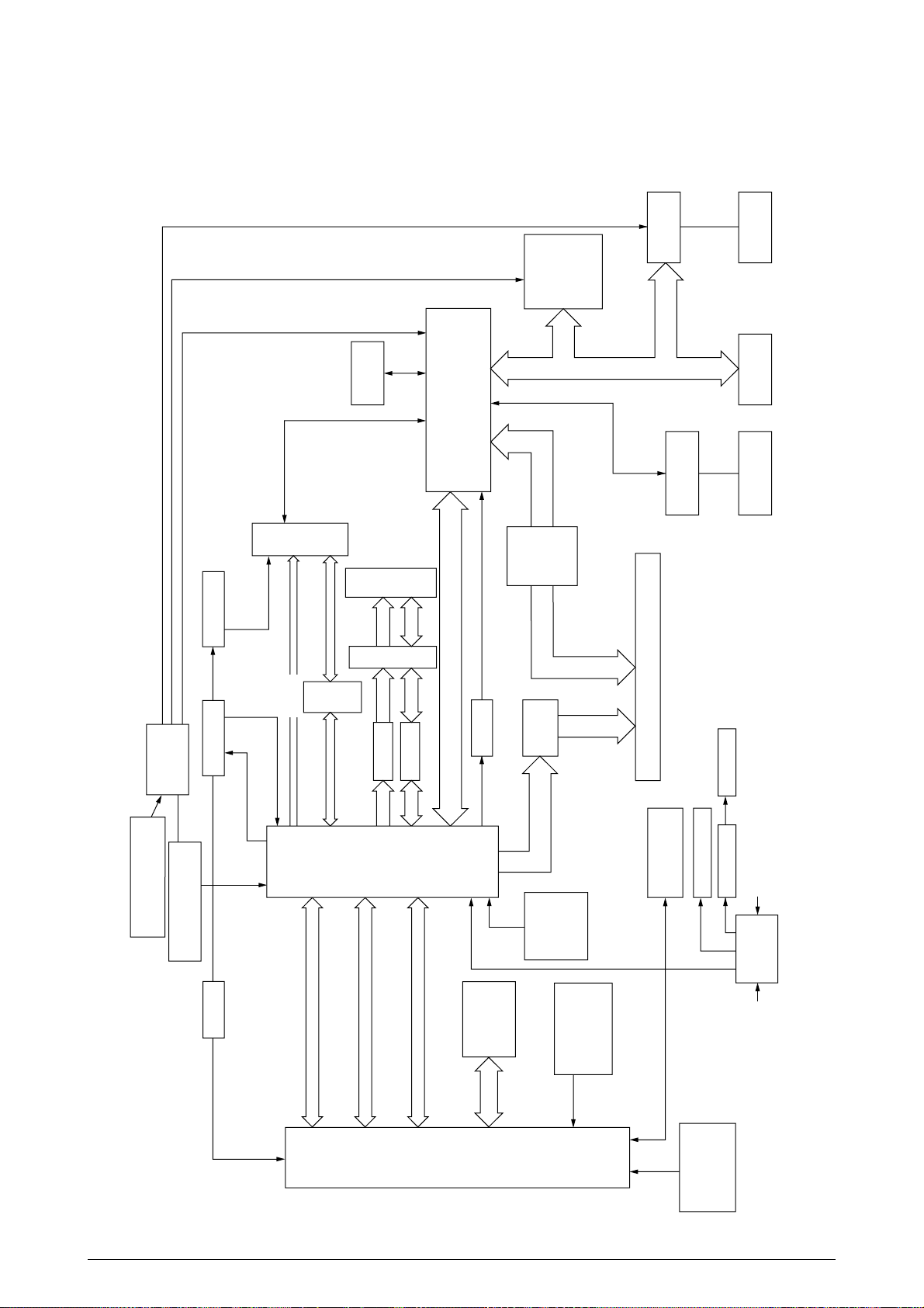
2. OPERATION DESCRIPTION
C9000, a tandem color electrophotographic page printer, adopts technologies such as 4992-LED
array, OPC, dry single-component non-magnetic developing, roller transfer and heat-compression
fusing. The printing method is black writing by shedding light on print areas.
Figure 2-1 provides the block diagram of this device.
Figure 2.1
41388601TH Rev.2 11 /
Page 12
2.1 Main Control Board (CRM-PWB)
PPC
750
L2
Cache
Delay
Delay
Buf
16244
Buf
16244
IF Bus
EEPROM
A
D
Cont
Y, M, C and K Video Data
PU-CU I/F,
Operator Panel
A/D,Cont
A/D, Cont(SUB Bus)
14.31818MHz
Crystal Resonator
CY2292
CY2308
FET SW
162212
FLASH ROM
FLASH DIMM
×3
SDRAM DIMM
·4
IMI1530
Fluctuation Circuit
Internal-CLK-
Setting
Resistance
Reset
DS1834
to C2 and
3.3V ICs
to 5V ICs
PU Board Connector, 200 Pins
Inverter
RESET-P
2.0V
Regulator
2.5V
Regulator
C1 LSI
MHM
2030-002
C2 LSI
MHM2031-002
CDC516
80MHz
LVC244
LVC161284
Centro USB
L60851
PCI Bus
LAN Board
IDE
HDD
LVC245
80MHz
80MHz
3.3V5V
40MHz
48MHz
33MHz
33MHz
·2
SPD
80MHz
×2
80MHz
×16
A,Cont
A,Cont A,Cont A,Cont
DDD
Figure 2-2 provides the block diagram of the main control board (CRM-PWB).
Figure 2.2
41388601TH Rev.2 12 /
Page 13

(1) CPU
The CPU is 64-bit bus RISC processor PowerPC750, which receives an input of 80MHz
(=BUS CLK) and operates at 400MHz, four-times the input.
(2) Secondary Cache SRAM
SRAM is included as a secondary cache of the CPU on the board.
(3) ROM
The ROM is inserted into the three 168-pin DIMM slots. The slot A is for a program ROM
and the slot B is for the Japanese Kanji font. The slot C is not assigned.
(4) RAM
The RAM is inserted into the four 168-pin DIMM slots. The DIMMs must be fitted in
descending order of the type No. labeled on each of them into the slots 1, 3, 2 and 4.
SDRAM DIMM Specifications:
Speed: PC100 or more
Capacity: 64/128/256MB
Configuration: Without parity and ECC. Requires the SPD information. Number of
chips contained = 8 or 16.
(5) EEPROM
The EEPROM (16Kb), an 8-pin DIP package, is inserted into the IC socket supplying the 3.3V
power. Settings for controlling the controller block are stored in the memory.
(6) Flash ROM
A 2-megabyte flash ROM is surface-mounted on the CRM board. The flash ROM, composed
of four chips of 256 kilo x 16 bits, can store fonts and macros.
(7) Memory Control LSI (CI)
A 696-pin BGA package ASIC made by NEC, which is equipped with a cooling heat sink and
mainly controls the CPU I/F, memory, video data compression and decompression, and PUvideo I/F.
(8) Interface Control LSI (C2)
A BGA package ASIC made by Toshiba, which controls the PU command I/F, operator panel
I/F, IDE I/F, Centronics I/F, USB I/F, PCI I/F, EEPROM and SPD (SDRAM DIMM) I/F.
(9) IDE HDD
An IDE connector is surface-mounted on the board to which an IDE HDD, assembled using
molds for the purpose, is connected. The IDE HDD is used for storing font data, spooling
edited video data temporarily and registering form data.
(10) PCI Bus Option
Two PCI I/F slots are provided for option board use. The bus, which uses an Oki Data original
connector, can accept an Ethernet board.
(11) Host Interface
Standard: Centronics two-way parallel I/F (IEEE-1284-compliant)
USB (USB1.1-compliant)
Additional Board: (connected to PCI BUS)
Ethernet Board
41388601TH Rev.2 13 /
Page 14
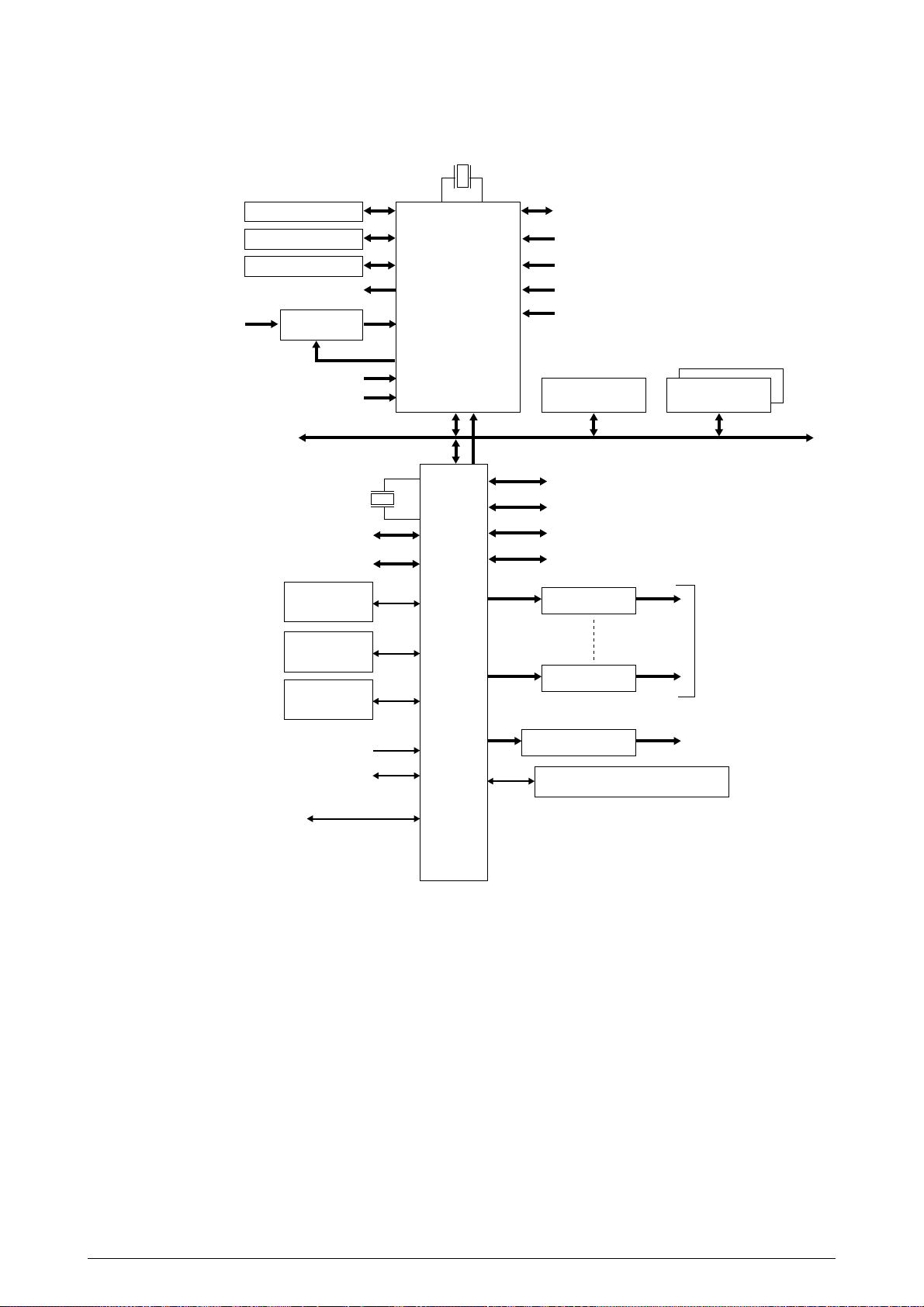
2.2 Engine Control Board (K73 PWB)
28MHz
Control Panel
Duplex
Cassette 2/3
Analog output
(Color registration sensor adjustment)
Analog input
(Temperature change)
Analog Input
Switch
Analog input (OHP)
Analog input (Various densities)
CPU BUS
32bit Video I/F
Heater control
Fuse Cut Driver
EEPROM
Toner and ID sensors ID check
D/A
48MHz
CU I/F
CPU
MSM66Q577
A/D CON
LSI
(VIDEO MEM
Containing
4Mbit DRAM)
Fan control
Cover front/upper open
Stacker full
Test switch
(Power supply cooling)
8Mbit(1MByte)
Motor interruption
UART interruption
K Head I/F
Y Head I/F
M Head I/F
C Head I/F
Motor Driver
Motor Driver
DC Motor Driver
High-Voltage Power Supply
Serial Interface (2 channels)
FLASH
256Kbit(32KByte)
SRAM
9x Pulse Motors
DC Motor
(Geared Motor)
×
2
Paper Feed System Sensors
(Paper Feed, Paper Registration and Eject Sensors)
MT Sensor (Stage position and paper empty)
Cassette 1 Sensor (Paper empty and near empty)
Shutter, clutch, belt and fuser checks
Cassette size
Figure 2.3
The engine control block (PU) is controlled by the engine control board (K73 PWB) which consists
of a CPU (MSM66Q577), general LSI chip, flash ROM, EEPROM, pulse motor drivers, and video
memory (see Figure 2.3).
(1) CPU
This, a 16-bit CPU with an AD converter (OKI MIM66Q577), controls the entire system.
(2) General LSI
This LSI (MG63P011-001LA), which is contained in the printer engine control block,
incorporates 4 megabits of video memory and has functions such as engine-controller
interfacing, LED interfacing, motor control, sensor input, video memory control, main scan
color misalignment correction, skew correction and high-voltage power supply control.
41388601TH Rev.2 14 /
Page 15

(3) Flash ROM
8 megabits of flash ROM (MBM29F800TA-70) which stores PU programs.
(4) EEPROM
4 kilobits of EEPROM (NM93C66N-NW) which is mounted on the board with an IC socket and
stores correction values.
(5) Pulse Motor Driver
The pulse motor driver (A2918, A2919, A3955) drives nine pulse motors to revolve the EP
and carry media.
(6) SRAM
This SRAM (62256LFP-7LL) is used as working memory of the CPU.
2.3 Power Units
There is a low-voltage power unit, which consists of an AC filter circuit, low-voltage power circuit
and heater driver circuit, and a high-voltage power unit which supplies a high-voltage power circuit.
(1) Low-Voltage Power Unit
This circuit generates the following voltages:
Output voltage Use for
+3.3 V Logic circuit power supply
+3.8V Logic circuit power supply
+5 V Motor and drive voltage for high-voltage power supply
+32 V OP Amp, High-voltage power supply
+12 V LED head
(2) High-Voltage Power Unit
This circuit generates the following 34V or more voltages, which are required for electrophotographic process, according to control sequences from the control board.
Output Voltage Use for Remarks
CH -900 to -1400±50V Voltage to charging roller
DB Y, M, C: -10 to -400V/+300V Voltage to developing roller
K: -10 to -400V/+300V
SB Y, M, C: -100 to -700/0V Voltage to toner supplying roller
TR 0 to 7KV Voltage to transfer roller Variable
41388601TH Rev.2 15 /
Page 16
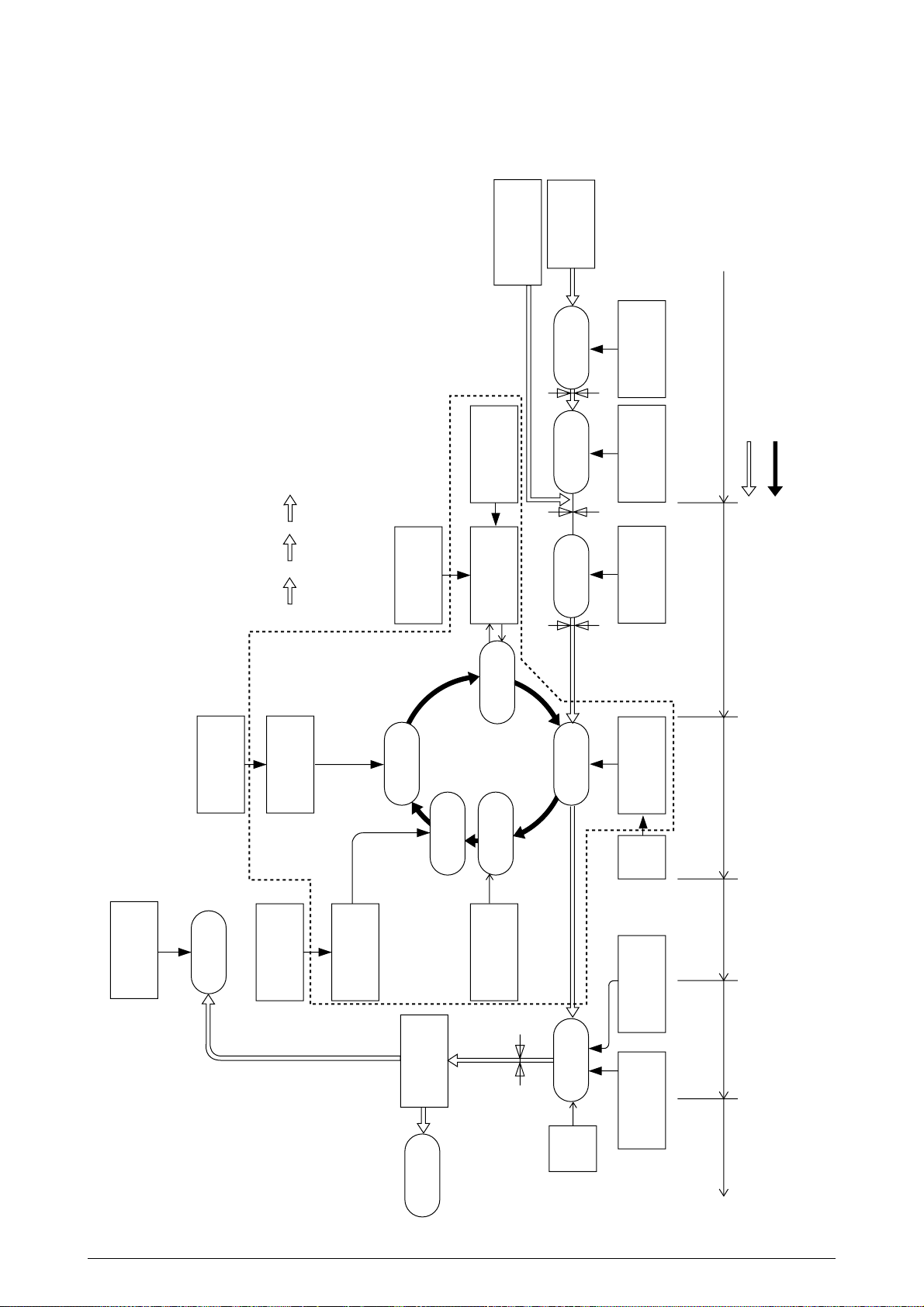
2.4 Mechanical Processes
Paper Eject Roller
Paper Ejection
(Face down)
Power Supply
Charging Roller
Cleaning Blade
Paper Path
Selection
Heat Roller
Ejection
Roller
Fusing
Backup Roller
Control Signals
LED Head
Developing Roller
Power Supply
Toner Cartridge
Transfer Roller
Registration
Roller 1
Paper loading
Hopping Roller
Power
Supply
Registration
Roller 2
Paper Ejection Fusing Cleaning Transfer
Paper carriage Paper advance
Paper traveling
OPC drum revolution
Transfer
Charging
Expose
Development
Cleaning
Paper Eject Sensor
Paper Feed Sensor 1
Paper Ejection
(Face up)
Paper Feed Sensor 2
Multipurpose
Tray
Paper Cassette
Paper
registration
Paper
registration
(MT, 1ST, 2ND)
Write Sensor
x 4
K
YMC
Figure 2.4 shows the mechanical processes of the printer.
41388601TH Rev.2 16 /
Figure 2.4
Page 17

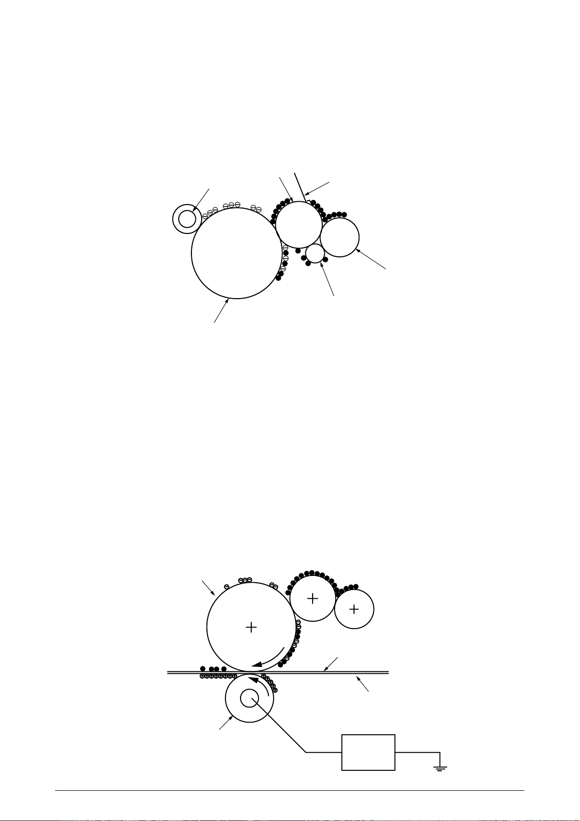
2.4.1 Electrophotographic process
(1) Electrophotographic process
The following is the outline of electrophotographic process:
1 Charging
DC voltage is applied to the charging roller and the surface of the OPC drum is negatively
and evenly charged.
2 Exposure
The LED head, under image signals, emits light to the negatively charged surface of the
OPC drum. The radiated portions of the drum surface attenuate in negative charge
according to the intensity of the light and, based on the surface potentials, a latent
electrostatic image is formed on the drum surface.
3 Development
Negatively charged toner contacts the OPC drum and, by electrostatic force, adheres to
the latent electrostatic image to form a clear image on the drum surface.
4 Transfer
Paper is placed on the surface of the OPC drum, and positively, or opposite to the polarity
of the toner, charged by the transfer roller on its back to transfer the toner image to the
paper.
5 Cleaning
The cleaning blade removes residual toner from the OPC drum after the transfer.
6 Fusing
The toner image on the paper is fused into place through the application of heat and
pressure to it.
41388601TH Rev.2 17 /
Page 18
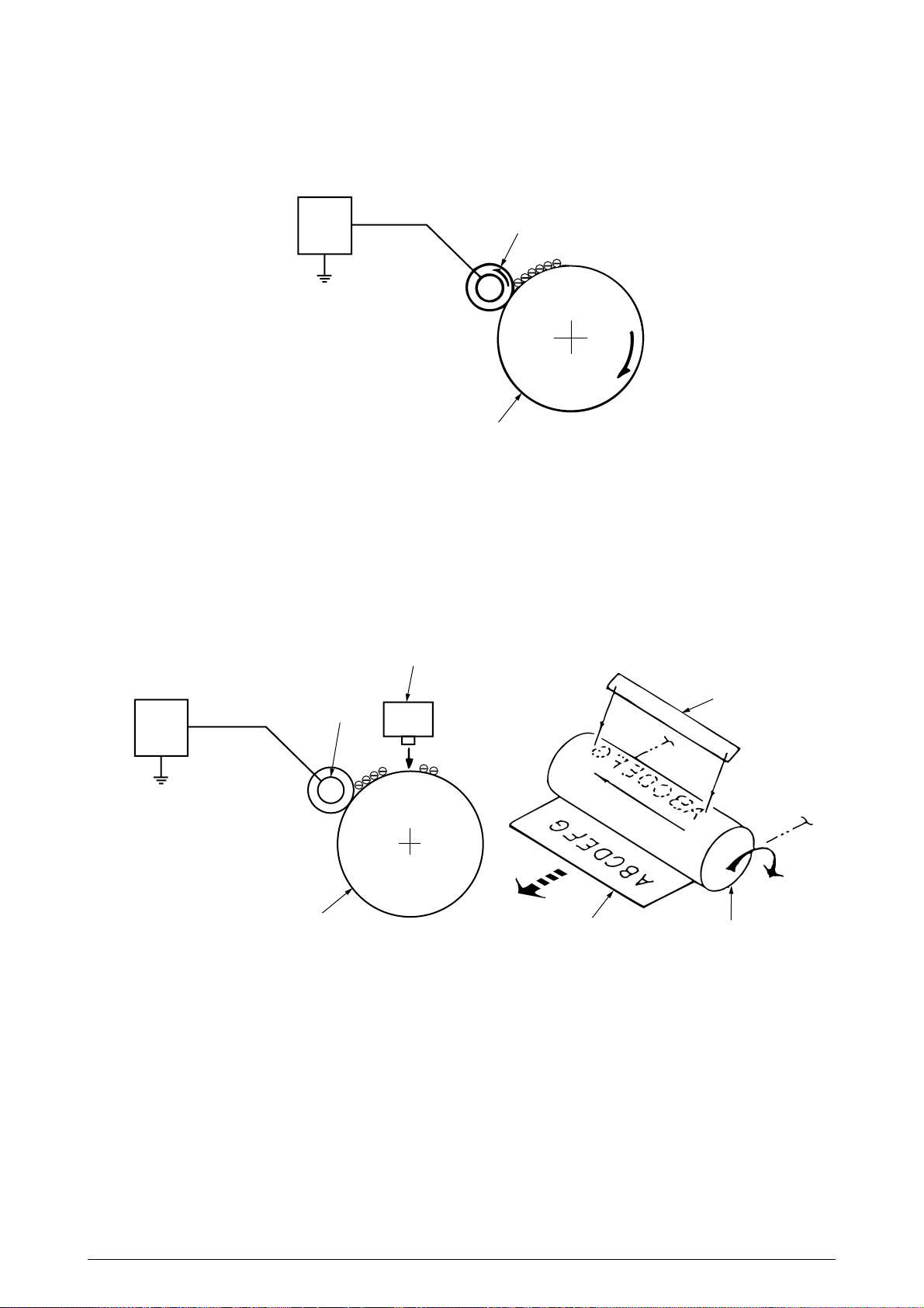
(2) Charging
Negative DC voltage is applied to the charging roller contacting the surface of the OPC drum.
Power
Unit
Charging roller
OPC drum
(3) Exposure
The negatively charged surface of the OPC drum is radiated with light from the LED head.
The negative charge of the radiated portions of the drum surface attenuates in response to
the intensity of the light and a latent electrostatic image responsive to the potentials of the
surface is formed on the drum surface.
LED head
Power
Unit
Charging roller
OPC drum
Paper
LED head
OPC drum
41388601TH Rev.2 18 /
Page 19
(4) Developing
By the adhesion of toner to the latent electrostatic image on the drum surface, the image is
changed to a toner image. The developing is processed at the contact part between the OPC
drum and the developing roller.
1 The sponge roller causes toner to adhere to the developing roller. The toner becomes
negatively charged.
Developing roller
Charging roller
OPC drum
Developing blade
Sponge roller
Developing roller
2 The developing blade removes excess toner from the developing roller and a thin layer
of remaining toner is formed on the developing roller.
3 The toner is drawn by the latent electrostatic image at the contact portion between the
OPC drum and the developing roller.
The latent electrostatic image on the drum surface is made visible with the toner.
(5) Transferring
The transfer roller, which is made of conductive sponge, presses paper against the surface
of the OPC drum and brings the paper into intimate contact with the drum surface.
The paper is placed on the drum surface and positively (opposite to the charge of the toner)
charged by the transfer roller on its back.
Applying positive high voltage from the power supply to the transfer roller moves the positive
charge induced by the transfer roller to the paper surface at the contact portion between the
transfer roller and the paper, the paper surface drawing the negatively charged toner from the
drum surface.
OPC drum
Paper
Carrier belt
Transfer roller
Power unit
41388601TH Rev.2 19 /
Page 20
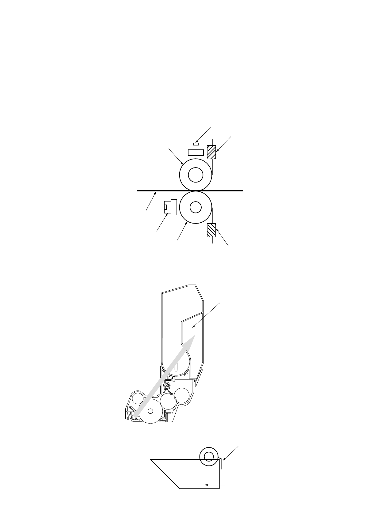
(6) Fusing
When passed between the heat roller and the backup roller, the toner image transferred to
the paper is fused into place by the application of heat and pressure to it.
The Teflon coated heat roller is heated by the built-in heat roller of 800W/backup roller of
500W (halogen lamp). The fusing temperature is controlled by the sum of the temperature
detected by the thermistor moving over the surface of the heat roller and the temperature
detected by the thermistor moving over the surface of the backup roller. A thermostat, which
is provided for safety, becomes open by a heat roller temperature rise of not less than fixed
degrees and cuts off voltage supply to the heater. The backup roller is being pressed against
the heater by the pressure springs on both sides.
Thermostat
Thermistor
Heat roller
Paper
Thermostat
Backup roller
Thermistor
(7) Cleaning
Non-fused, residual toner on the OPC drum is scraped with the cleaning blade and collected
in the waste toner area of the toner cartridge.
Waste toner area
(8) Cleaning
Residual toner on the transfer belt is scraped with the cleaning blade and collected in the
waste toner box of the transfer belt unit.
41388601TH Rev.2 20 /
Cleaning blade
Waste toner box
Page 21
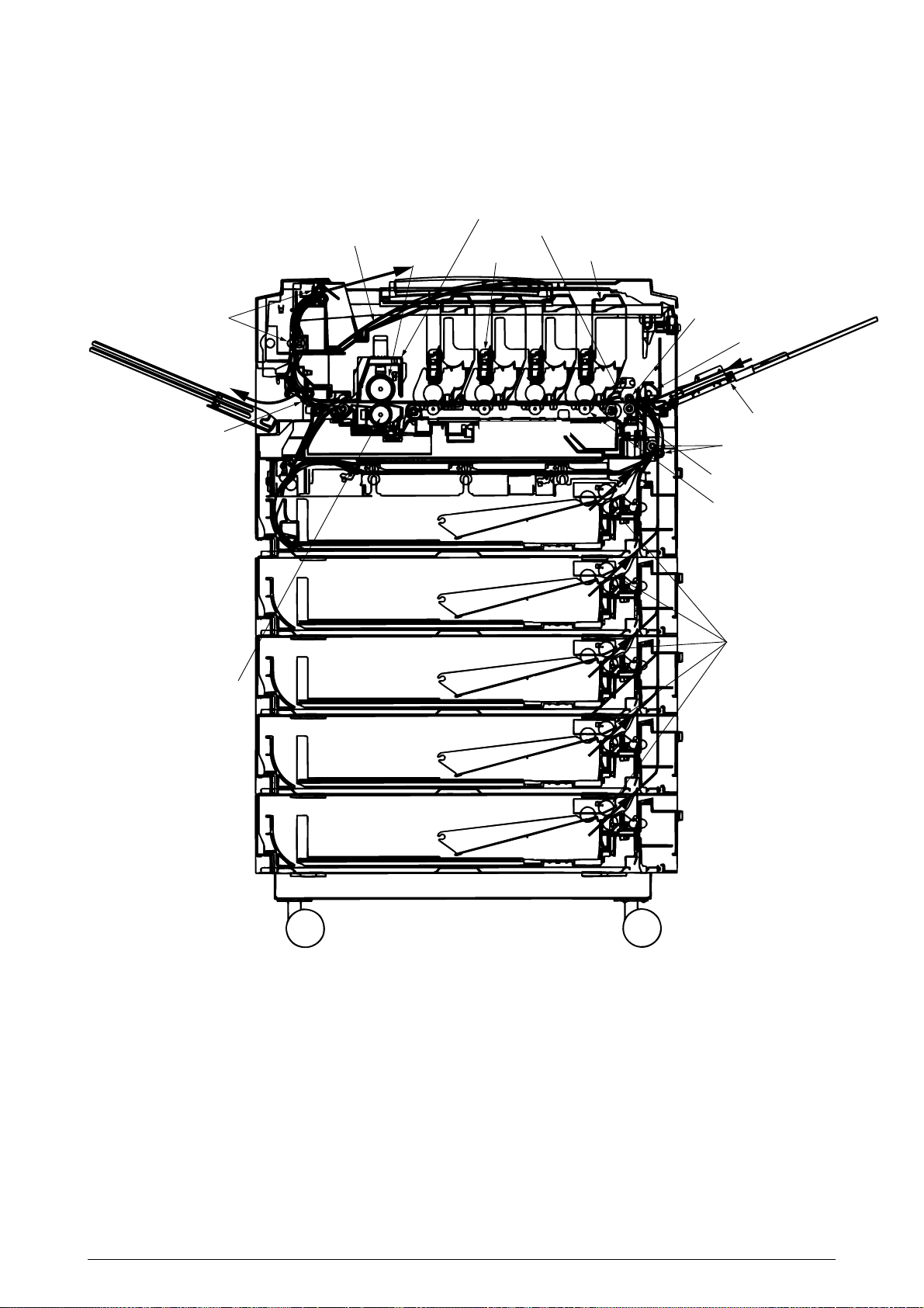
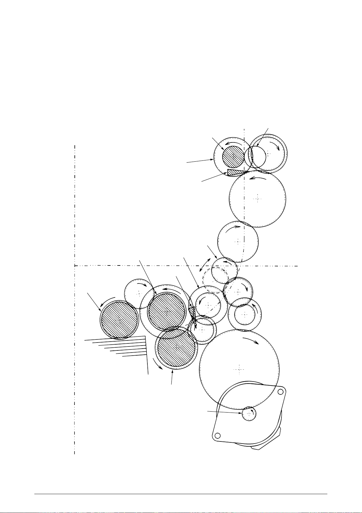
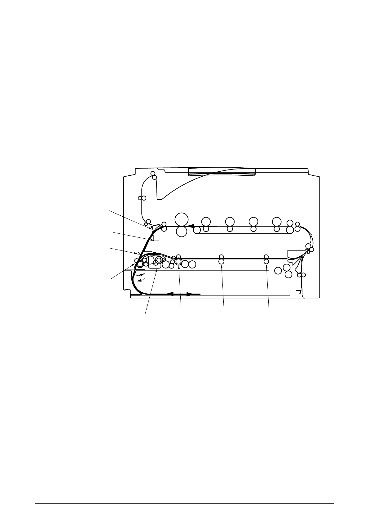
2.4.2 Paper running process
Figure 2.5 shows how paper moves in the C9000.
Face-down stacker
Heat roller
Fuser
Registration roller Assy (B)
4 x LED heads
4 x LED Units
Eject roller
Eject roller
Backup roller
Low-voltage power supply
Cassette 1
Cassette 2
Cassette 3
Cassette 4
Belt unit
High-voltage power supply
Registration roller Assy (B)
Hopping roller
Multipurpose tray
Registration roller Assy (A)
Cleaning blade
Transfer roller
Feed roller
Cassette 5
Figure 2.5 Paper Route
41388601TH Rev.2 21 /
Page 22
(1) Paper Loading from 1st Tray
1. The paper loading motor runs (CCW), the paper loading clutch is engaged and, until the
entrance cassette sensor is turned on, paper is advanced (the on/off operations of the
paper loading clutch control the pickup roller).
2. After the paper turns the entrance cassette sensor on, the paper is forwarded a further
fixed length and touches the registration roller Assy (A) (this corrects paper skew).
3. The electromagnetic clutch is engaged and the paper is carried onto the carrier belt.
Pickup roller
Registration roller Assy (B)
Entrance belt sensor
Feed roller
Electromagnetic clutch
Registration motor
Entrance sensor
Electromagnetic clutch
Entrance cassette sensor
Registration roller Assy (A)
Loading sensor
Paper
Retard roller
Loading motor
Figure 2.6
41388601TH Rev.2 22 /
Page 23
(2) Paper Loading from Option Tray
1. The paper loading motor runs (CW), the paper loading clutch is engaged and, until the
carrier sensor on a tray which sits atop a loading tray is turned on, paper is advanced.
2. After the paper turns the carrier sensor on, the paper is forwarded a further fixed length
and touches the carrier roller (this corrects paper skew).
3. The carrier clutch is thrown in and the paper is fed into the main body.
Pinch roller
Carrier roller
Carrier clutch
Carrier sensor
Upper tray
Optional paper loading tray
Pickup roller
Feed roller
Planet gear
Paper loading clutch
Paper loading sensor
Retard roller
Paper loading motor
Figure 2.7
41388601TH Rev.2 23 /
Page 24
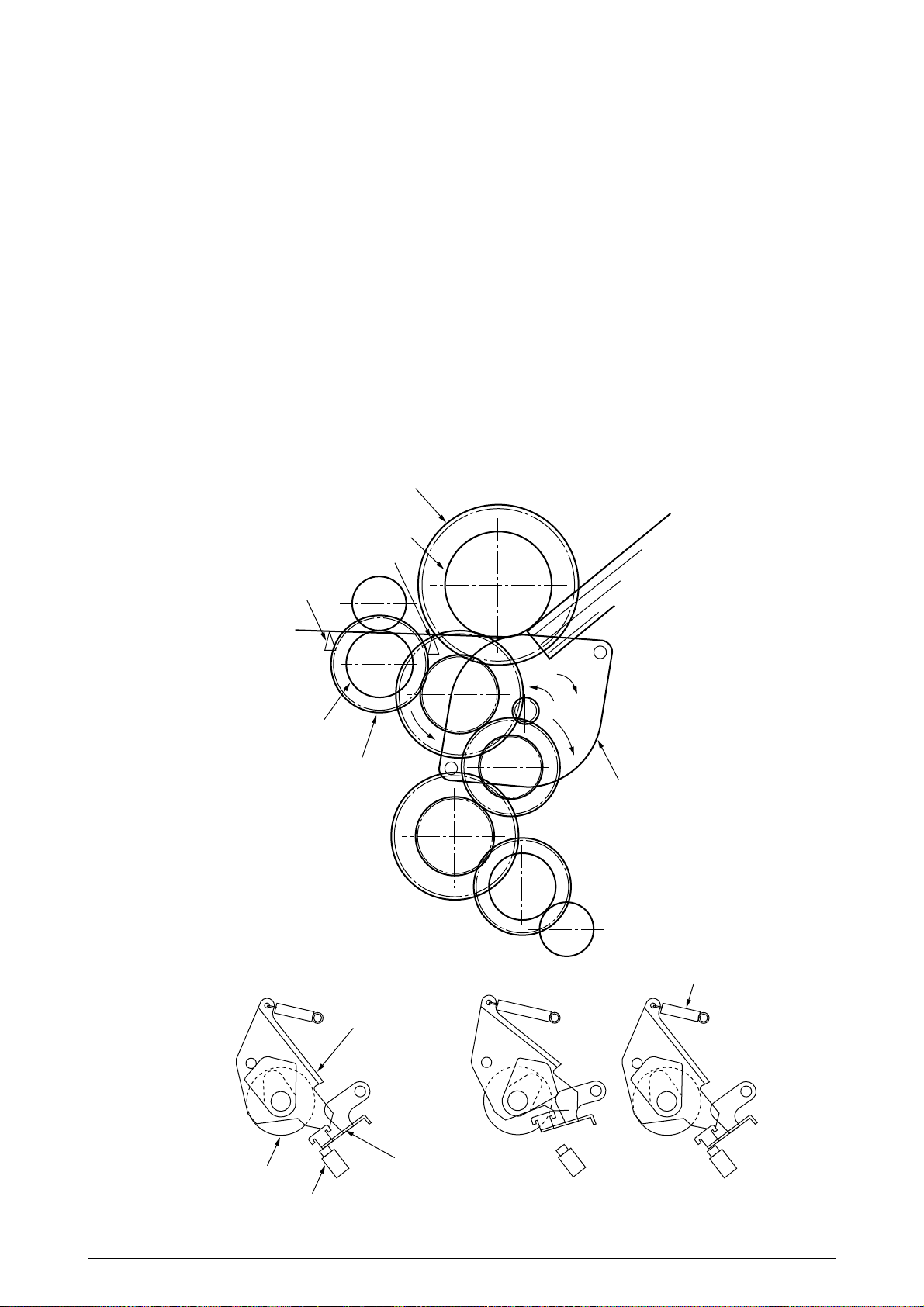
(3) Paper Loading from Multipurpose Tray (MT)
1. The release lever usually pushes down the hopping plate to a position to turn the micro
SW on (Figure 2.8-a).
2. The running of the motor in the (a) direction drives the MT feed roller, causing the cam to
turn. The cam pushes the release lever and the hopping plate picks up paper sent out by
the MT feed roller (Figure 2.8-b), where the registration roller Assy (B) does not move as
its one-way clutch gear (1) idles.
3. After the front edge of the paper turns the entrance sensor on, the paper is forwarded a
fixed length. The paper stops when its front edge reaches the registration roller Assy (B).
4. Concurrently, the cam pushes down the hopping plate. The release lever that has been
placed in its original position by the spring locks the hopping plate (Figure 2.8-c).
5. After the completion of the paper feed operation, the registration motor runs in the direction
of the arrow (b) to drive the registration roller Assy (B), where the one-way clutch gear does
not allow the MT feed roller to move.
Oneway clutch gear (2)
MT feed roller
Entrance sensor
Entrance belt sensor
Paper
Registration roller Assy(B)
Oneway clutch gear (1)
Relerse lever
Figure 2.8
b
a
Registration motor
Spring
Feed roller
Micro SW
Figure 2.8-a Figure 2.8-b Figure 2.8-c
41388601TH Rev.2 24 /
Hopper plate
Page 25
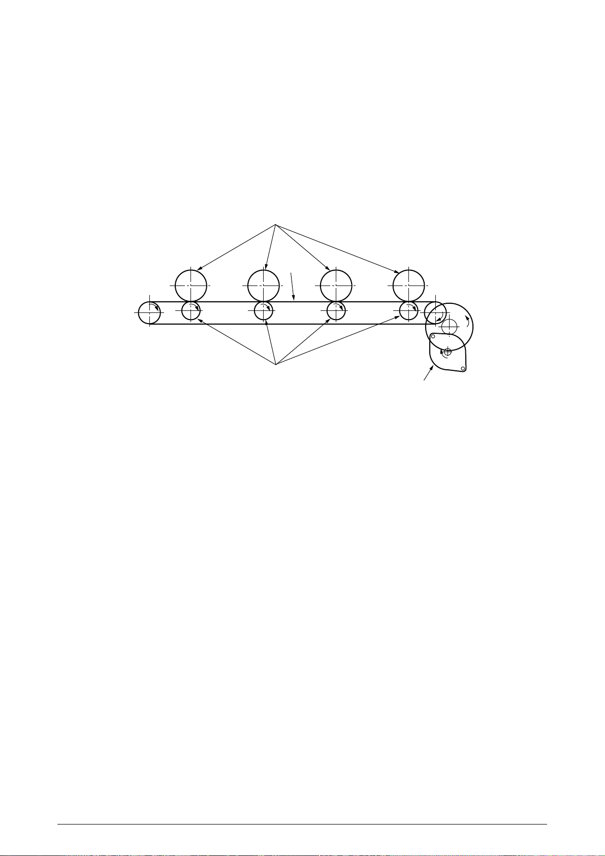
(4) Carrier Belt
1. The running of the carrier belt motor in the direction of the arrow (a) drives the carrier belt.
The belt unit sits with one carrier roller immediately below each color’s drum, and the
carrier belt between them. By the application of a fixed voltage, the carrier belt and carrier
roller feed paper on the carrier belt into the fuser unit, transferring a toner image from
each color’s drum.
Drum
Carrier belt
KYMC
Carrier (transfer) roller
Carrier (transfer) belt motor
Figure 2.9
41388601TH Rev.2 25 /
Page 26
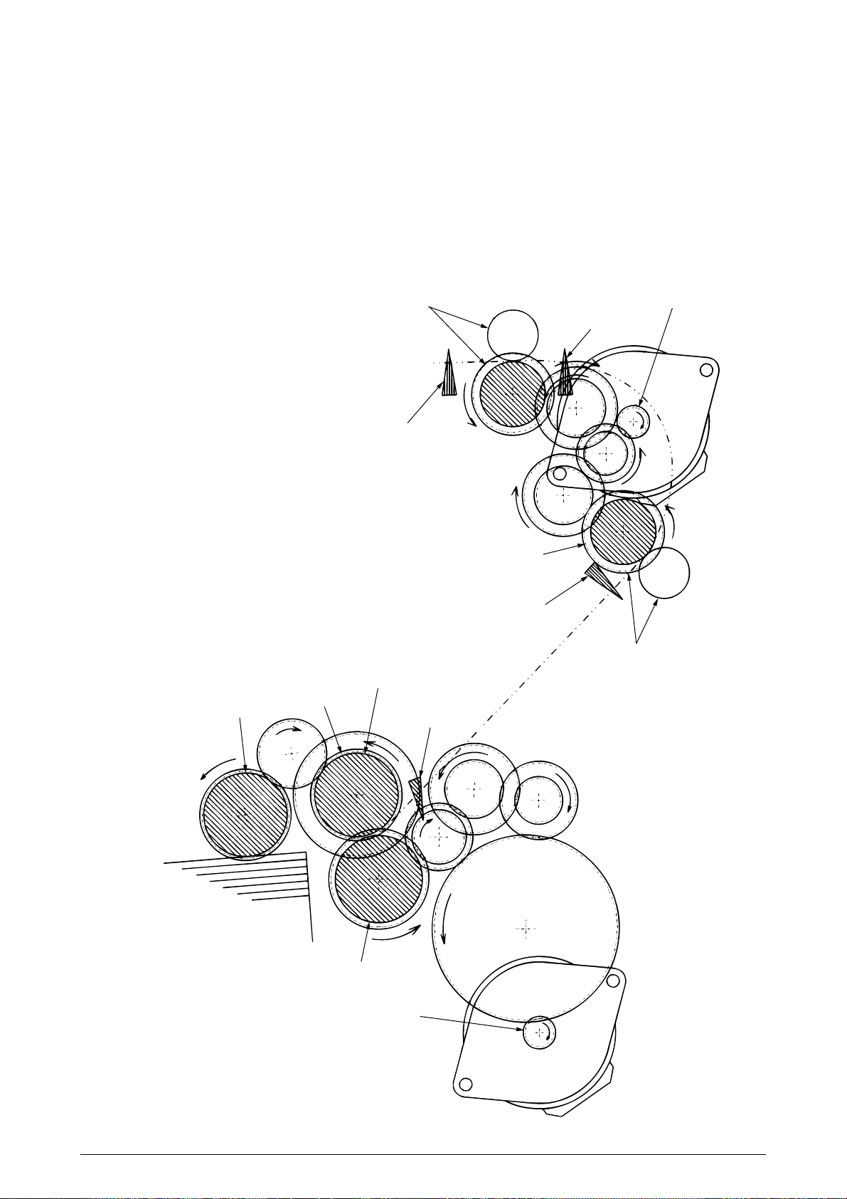
(5) Driving and Up-and-Down Movements of I/D Unit
1. The I/D unit driving and up-and-down movements are effected by a single-pulse motor.
The running of the main motor in the direction of the arrow (a) turns the lever 1 to the left.
Then, the lever 2 that was lifted by the lever 1 lowers to move down the I/D unit. After the
up-and-down sensor is turned on (Figure 2.10-c), the specified downward pulsing places
the I/D unit in its lowest position (or equivalently, printing position).
The drum gear engages with the driving gear and starts revolving to transfer an image on
the drum to running paper, where the one-way gear idles upon placement of the lever in
its lowest position.
2. With the running of the main motor in the direction of the arrow (b), the lever 1 pushes up
the I/D unit via the lever 2. After the up-and-down sensor is activated (Figure 2.10-d), the
lever 1 lifts the I/D unit to a specified level and stops to keep space to an extent between
the drum and the carrier belt (Figures 2.10-c and 2.10-e).
The drum gear is not engaged with the driving gear and does not revolve.
3. When the two pins of the up-and-down sensor are pushed up by the I/D unit, and touches
and electrically connected to the plate above the pins, the sensor recognizes the on state.
When the two pins are pushed down by the I/D unit, and separated and insulated from the
plate, the sensor recognizes the off state.
The installation of the I/D unit can also be verified by recognizing the off state of the upand-down sensor.
Lever 2
I/D unit
Drum
One-way gear
Driving gear
a
Figure 2.10-a Figure 2.10-b
41388601TH Rev.2 26 /
Lever 1
b
Page 27
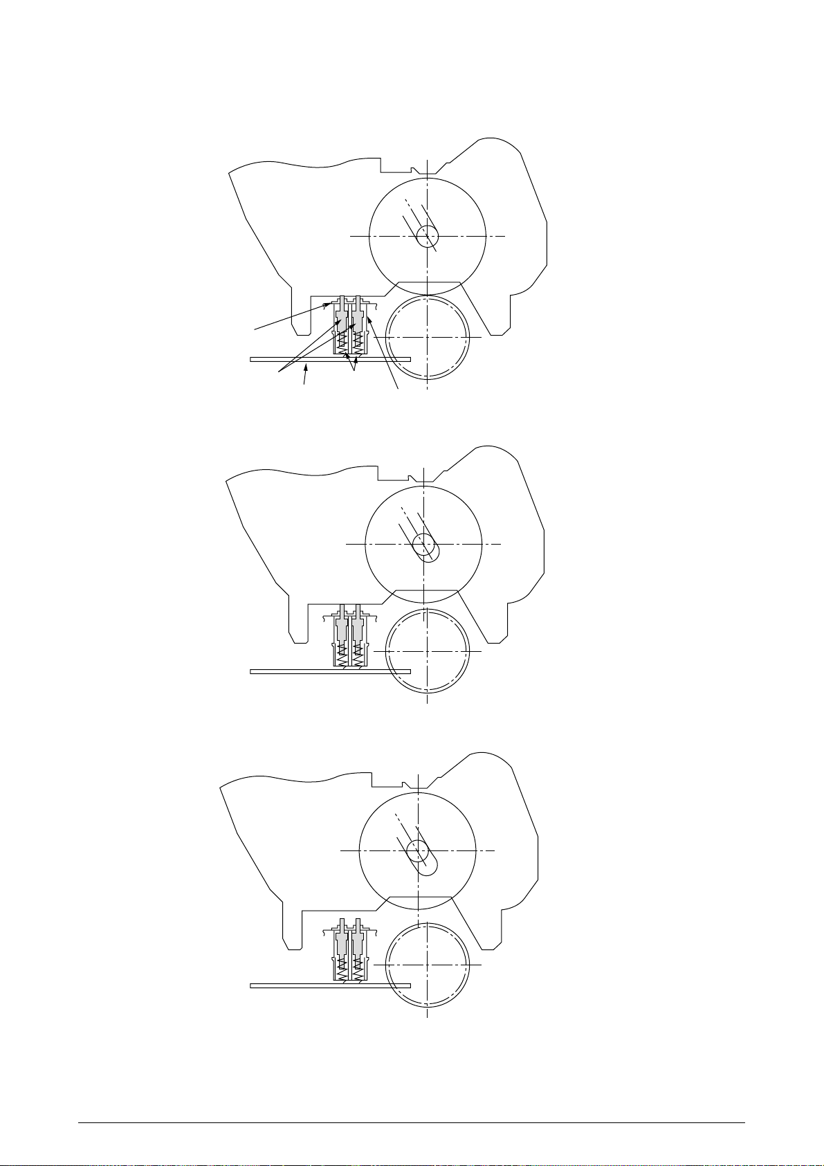
Plate
Pin Spring
Board
Up-and-down Sensor
Figure 2.10-c
Figure 2.10-d
Figure 2.10-e
41388601TH Rev.2 27 /
Page 28
(6) Fuser Unit and Paper Ejection
1. A single-pulse motor drives the fuser unit and the eject rollers.
In response to the running of the heat motor in the direction of the arrow (a), the heat roller
turns. This roller fuses a toner image to paper by heat and pressure.
2. At the same time, the four eject rollers move to eject the paper.
3. The paper separator solenoid switches the path back and forth between the route to the
face-up stacker and the route to face-down stacker.
Eject rollers
Fuser unit
Fuser motor
Heat rollers
a
Paper separator
Face-up stacker
Figure 2.11
41388601TH Rev.2 28 /
Page 29
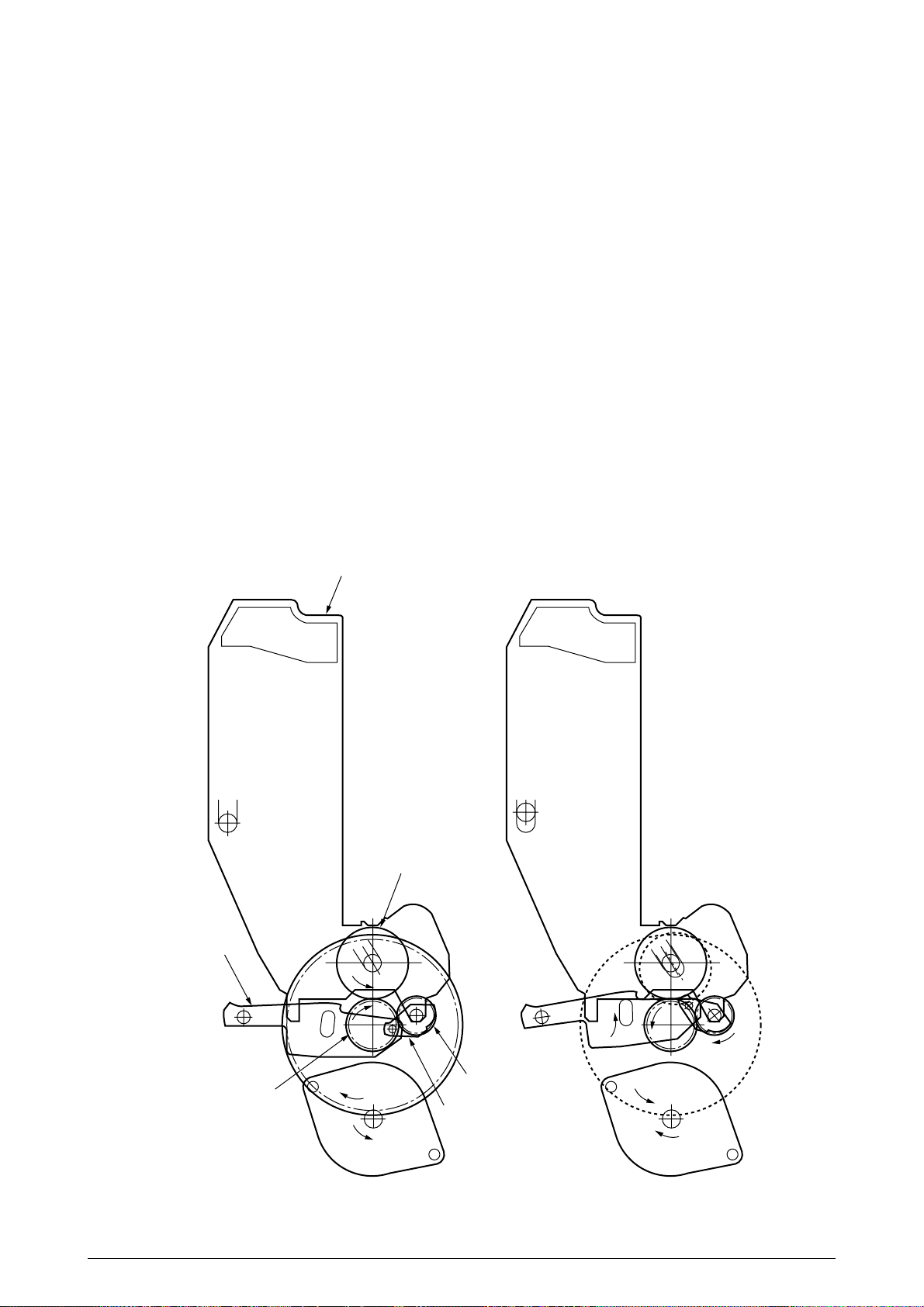
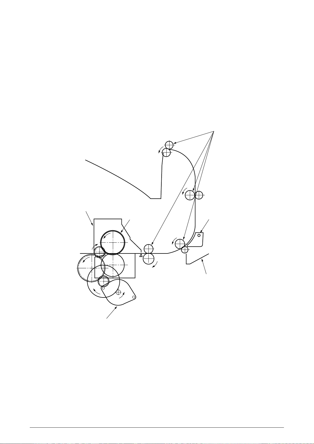
(7) Duplex Unit
1. When the duplex unit receives an instruction from the printer to print on both sides of a
sheet of paper, the solenoid opens the separator after the completion of one side printing
of a sheet of paper sent from the tray. The path is switched to that to the duplex unit.
At this time, as the roller (1) turns in the direction of the arrow “a,” the paper is retracted
on the rear of the cassette.
2. When fixed time has elapsed after the front edge of the paper passes through the duplexin sensor, the rollers reverse and the roller (1) turns in the direction of the arrow “b” to feed
the paper into the duplex unit. After that, the paper passes through the rollers (2), (3) and
(4), and ejected with the other side printed, and fed again into the printer.
Separator
Solenoid
Duplex-in sensor
Roller(1)
Motor
a
b
Roller(2)
Roller(3)
Roller(4)
Figure 2.12
41388601TH Rev.2 29 /
Page 30
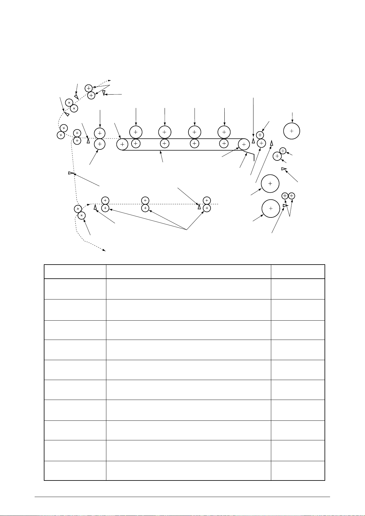
2.5 Sensor
r
2.5.1 Paper related sensors
Face-down paper eject sensor
Face-down sensor
Paper eject sensor
Backup roller
Duplex roller
Paper eject roller
Heat roller
Driving roller
Duplex-in sensor
Duplex rear sensor
Stacker full sensor
C drum
Carrier belt
Duplex front sensor
Duplex feed roller
Entrance belt sensor
K drumY drumM drum
Driving roller
Belt cleaning blade
Registration roller B
Entrance MT sensor
1st feed roller
2nd feed roller
MT feed roller
Pinch roller 2
Pinch roller 1
Registration roller A
Entrance cassette senso
Auxiliary roller
Carrier sensor
Sensor
Entrance MT Sensor
Entrance Cassette sensor
Entrance Belt sensor
Detects the beginning of incoming paper to determine the timing for
switching from hopping to carriage.
Detects the beginning of transferred paper and, based on the time taken
until the paper front edge reaches the sensor, determines the paper length.
Paper Eject sensor
Detects the beginning and end of paper to determine the paper ejection
timing.
Duplex-In sensor
Detects the beginning of paper which enters into the duplex unit to
determine the time taken until the reversed rollers turn in forward direction.
Duplex Rear sensor
Detects the beginning of paper after the turns in reverse direction, in the
duplex unit.
Duplex Front sensor
Detects the end of paper after the turns in reverse direction to determine
the paper ejection timing, in the duplex unit.
Stacker Full sensor
Face-Down Paper Eject
sensor
Face-Down Route sensor
Detects the face-down stacker full of paper.
Detects paper carriage to the paper eject roller to determine the timing for
job offset operation.
Detects the face-down carrier route jammed with paper when it has a
paper jam.
Function
Sensor status
ON
: Paper exists.
OFF
: Paper is empty.
ON
: Paper exists.
OFF
: Paper is empty.
ON
: Paper exists.
OFF
: Paper is empty.
ON
: Paper exists.
OFF
: Paper is empty.
ON
: Paper exists.
OFF
: Paper is empty.
ON
: Paper exists.
OFF
: Paper is empty.
ON
: Stacker is full.
OFF
: Stacker is empty.
ON
: Stacker is full.
OFF
: Stacker is empty.
ON
: Stacker is full.
OFF
: Stacker is empty.
Carrier sensor
41388601TH Rev.2 30 /
Detects paper carriage from the option tray.
ON
: Stacker is full.
OFF
: Stacker is empty.
Page 31

2.5.2 Other sensors
1 Paper Empty sensor
This sensor checks whether the paper cassette is empty.
2 Paper Near sensor
This sensor checks whether the paper cassette is near empty.
3 MPF Paper Empty sensor
This sensor checks whether the front feeder has paper.
4 MPF Hopping switch
This microswitch checks whether the front feeder table is in the up position or in the down
position.
5 Stacker Full sensor
This sensor checks whether the stacker is full.
6 Paper Size switch
This sensor detects the size of paper in the paper cassette.
7 EP Up/Down sensor (one for each of colors, Y, M, C and K)
This sensor checks whether the I/D unit is in the up position or in the down position.
8 Toner K, Y, M and C sensors
By measuring the time interval between regular opening movements of each sensor’s lever,
the sensor checks whether its toner cartridge is empty.
9 Temperature sensor
See Section 2.6 (Transfer Control Responds to Environmental Changes)
0 Humidity sensor
See Section 2.6 (Transfer Control Responds to Environmental Changes)
A OHP sensor
This sensor detects the presence or the absence of transparencies.
B Alignment sensor
When color misalignment has been corrected, this sensor reads the alignment pattern printed
at the right and left ends of the transfer belt (see Section 2.13).
41388601TH Rev.2 31 /
Page 32

2.6 Color Misalignment Correction
C9000 is equipped with multiple LED heads, which can result in color misalignment.
The mechanically induced color misalignment is automatically corrected as follows:
(1) Color alignment to be corrected
1 Color misalignment in X-axis direction (Positional error caused by LED head)
2 Color misalignment in slanting direction (Positional error caused by LED head)
3 Color misalignment in Y-axis direction (Positional error caused by I/D unit and LED head)
(2) Correcting
Printing the preset color misalignment detection pattern on the belt and, by a reflection
sensor, reading the printed pattern detects each color’s misalignment value to determine its
correction value. The correction value is used to change each color’s (Cyan, Magenta and
Yellow) writing timing in comparison with that of Black.
2.7 Transfer Control Responds to Environmental Changes (Room Temperatures and
Relative Humidities)
C9000 measures room temperature and relative humidity using a room temperature sensor and
humidity sensor, and calculates an optimum transfer voltage under its measurement environment
to perform real-time control on printing with the optimum voltage.
41388601TH Rev.2 32 /
Page 33

2.8 Paper Jam Detection
C9000 detects paper jams after power-on and during printing. When a paper jam occurs, the
printer immediately suspends the printing operation. Opening the cover to remove the jammed
paper and closing it resumes the printing.
LCD Error Code
400
372
390
5-395
4-394
3-393
2-392
1-391
370
383
371
382
381
380
490
5-495
4-494
3-493
2-492
1-491
Error
Paper Size Error
The entrance cassette sensor does not turn off within fixed time
after it turns on. Loading of plural sheets of paper is sensed.
Misfeed from Duplex Carrier Assembly
Misfeed from Multipurpose Tray (MT)
Paper could not be loaded from the duplex carrier assembly.
Paper could not be loaded from the MT (the entrance MT
sensor does not turn on within fixed time after the hopping).
Misfeed from Cassette 1, 2, 3, 4 or 5
Paper could not be loaded from the cassette 1, 2, 3, 4 or 5 (the
entrance cassette sensor does not turn on within fixed time after
the hopping).
Duplex Paper Jam in Reversing
The duplex rear sensor does not turn on during the paper
reversing operation of the duplex unit.
Duplex Unit Entrance Paper Jam
The duplex-in sensor does not turn on during the paper loading
in the duplex unit.
Duplex Unit Input Paper Jam
Paper Ejection Jam
The duplex front sensor does not turn on during the operation.
The paper eject sensor does not detect the end of paper within
fixed time after sensing the beginning of it. The paper eject
sensor does not turn off after it turns on.
Paper Carriage Jam
The paper eject sensor does not turn on while paper is running
on the belt.
Loading Jam
Paper does not reach the entrance belt sensor or the MT sensor
after the completion of the hopping.
MT Paper Empty
Cassette 1, 2, 3, 4 or 5 Paper Empty
Printing occurs with no paper in the MT.
The cassette 1, 2, 3, 4 or 5 has no paper.
Description
Duplex-in sensor
Duplex Rear Sensor
Paper Ejection
Paper eject sensor
Duplex Entry
Duplex rear sensor
Entrance belt sensor
Paper Carriage
Duplex Input
Duplex front sensor
Entrance MT sensor
Cassette
Cassette
Cassette
Cassette
Cassette
1
2
3
4
5
Paper Ejection
Misfeed from MT
Entrance cassette sensor
Multipurpose T ray
(MT)
Misfeed from Duplex Unit
Misfeed from Cassette 1
Misfeed from Cassette 2
Misfeed from Cassette 3
Misfeed from Cassette 4
Misfeed from Cassette 5
41388601TH Rev.2 33 /
Page 34

2.9 Cover Opening
When the top cover of the printer is open, the cover open microswitch turns opens to cut off the highvoltage power supply, and outputs which are not less than 32V. At the same time, the CPU receives
CVOPN signals indicating the status of the microswitch and performs cover open operations.
Detection
Circuit
CPU
66577
P10, 5
P7, 6
71K-PCB
Top cover microswitch
+32V
COVOPN (2P)
High-voltage power supply board
HVOLT (16P)
detect
circuit
High-voltage power supply unit
detect
circuit
+32V
FCOVER(3P)
Duplex (16P)
Front cover
microswitch
+32V
Duplex unit
V71-PCB
41388601TH Rev.2 34 /
Page 35

2.10 Toner Low Detection
• Structure
This device consists of the stirring gear which revolves at a constant speed, the stirring bar, and
the magnet on the stirring bar. The stirring bar turns in synchronization with the protrusion of
the stirring gear.
Stirring gear
Link
Stirring bar
• Detection
A toner low condition is detected by measuring the contact time between the sensor lever magnet
and the stirring bar.
Toner low sensor
Sensor lever A
Toner Full Condition
• The stirring bar turns in synchronization with the
stirring gear.
Sensor lever B
• Since the opposite side is in toner, the stirring bar
turns by the force of the stirring gear even when
the stirring magnet is placed in its highest position.
Toner cartridge
Stirring bar
Toner Low Condition
• The stirring bar reaches its highest position, then
Sensor lever A
Toner low sensor
falls to its lowest position under its own weight
because of the absence of toner resistance on the
opposite side. In this situation, bar-magnet contact time becomes long. By measuring the time,
a toner low condition can be detected.
41388601TH Rev.2 35 /
Sensor lever B
Toner cartridge
Stirring bar
Page 36

Toner Full Condition (At warming-up,A4 transverse:16ppm *1)
t1
TNRSNS
T=2.3
Toner Low Condition (At warming-up,A4 transverse:16ppm *1)
t1
t1
1.12
TNRSNS
T=2.3
t1 1.12
• When the toner low condition is detected 20 consecutive times, toner low is detected.
(The toner low message is displayed when about 1000 A4 sheets at 5% density have been printed
after toner low had been detected.)
The detection is not performed until toner low occurs after the detection of toner low.
• When the toner full condition is detected 10 consecutive times, toner low is removed.
• When the toner sensor remains unchanged for more than 15 cycles of 2.3 seconds, the toner
sensor alarm is activated.
• The toner sensor does not perform the detection while the drum motor is not running.
* 16ppm is the print speed at warm-up. T and t1 change in proportion to the print speed.
41388601TH Rev.2 36 /
Page 37

2.11 Paper Size Detection
Via the cam tied to the paper guide of the paper cassette, the four tab pieces are driven according
to the set position of the paper guide.
Upon installation of the paper cassette, the microswitch detects the condition of the tab pieces and
the paper size is recognized.
Without Cassette
A3-Nobi
Tabloid
A3
B4
Regal 14"
Regal 13"
A4 in Portrait Orientation
Letter in Portrait Orientation
Executive
B5 in Portrait Orientation
Letter in Landscape Orientation
A4 in Landscape Orientation
A5
B5 in Landscape Orientation
A6
PSZSW1
0
0
1
1
0
0
0
1
1
1
1
1
0
0
1
0
PSZSW2
0
0
0
0
0
1
1
1
1
1
1
0
0
1
0
1
PSZSW3
0
1
1
0
0
0
0
1
1
0
0
1
1
1
0
1
PSZSW4
0
1
1
1
1
1
0
0
1
1
0
0
0
0
0
1
41388601TH Rev.2 37 /
Page 38

2.12 Operation at Power-on
2.12.1 Self-diagnostic test
(1) Initial test
The following checks are automatically performed at power-on.
(a)ROM check
(b)RAM check
(c) EEPROM check
(d)Flash ROM check
(2) ROM check
The ROM is checked by calculating a HASH value.
(3) RAM check
(a)Checking is conducted by RAM type. Out-of-specification RAM is judged as an error.
(b)The order of mounted RAMs is checked. Out-of-standard RAM is judged as an error.
(c) The RAM in each slot is checked by read-after-write operation.
(4) EEPROM Check
Specific data stored at the fixed EEPROM address is checked.
(5) Flash ROM Check
The flash ROM format is checked. Unformatted ROM is formatted after the read-after-write
checking.
(6) Option Unit Check
Checking whether the option units (including a HDD, NIC, option trays and the duplex unit)
are equipped with the printer is performed.
41388601TH Rev.2 38 /
Page 39

2.13 Color Misalignment Detection
Reflection-type optical sensors (Z71-PCB) are mounted at the right and left ends of the belt,
respectively, in front of the toner scraping (cleaning) blade which is at the back of the belt unit. The
color misalignment detection pattern is printed on the belt at the right and left ends each and, by
reading the patterns by the reflection-type optical sensors, the misalignment amounts are
measured with respect to Black to determine correction values. Then, the misalignment in mainscanning, sub-scanning and slanting directions is corrected.
These operations are performed at power-on, at cover-close and every 400 pages.
CMYK
ID
CMYK
Transfer
belt
LED head
Belt running direction
Color alignment sensors L and R
Transfer Belt
Color alignment sensor R
Belt running direction
Color alignment sensor L
(Bottom View)
Cleaning blade
Cleaning blade
41388601TH Rev.2 39 /
Page 40

2.14 Version Read of Periodically Replaced Units
The condition (new or used) of the I/D, fuser unit and belt unit are determined by an internal fuse
within the units. When the unit is powered on or the upper cover is opened and closed, the
printer scans for consumables fuses. If a conducting fuse is found, that unit's counter is reset
and the fuse is opened. The life counters of the consumables are checked at each power on
and each closing of the upper cover. Once a fuse is opened the consumable is judged used.
2.15 Life Counter for Replaceable Units
Each life of the periodically replaced units - I/D, fuse unit and belt unit is counted as shown in the
following table:
Unit Name
I/D
Toner Cartridge
Belt Unit
Fuser Unit
The number of drum revolutions is counted in the unit of letter
paper length + paper interval in continuous printing.
End of Life: Time when a distance equivalent to pages of 26K is
printed (on 3P/J).
The number of dots printed is counted. The used amount is
determined based on the counter value (See Section 2.16).
End of Life: Time when a toner-low error occurs.
The number of turns revolutions is counted in the unit of letter
paper length + paper interval in continuous printing.
End of Life: Time when the counter value reaches 80K.
One is counted every time when one page is passed.
End of Life: Time when the counter value reaches 80K.
2.16 Toner Consumption Detection
The used toner amount is detected by counting the number of dots printed.
The counting starts after toner-low is released. The sum of the counted values is stored in
EEPROM. When toner-low is detected, the amount used is forcedly set to 7%.
When the equivalent of pages of 1K on A4 and 5% duty is reached after that, toner-empty is
detected.
Condition
Action
Warning (the unit can still be used).
Do not use the unit anymore.
Warning (the unit can still be used).
Warning (the unit can still be used).
41388601TH Rev.2 40 /
Page 41

3. PARTS REPLACEMENT
This section describes the procedure for replacing the parts, assemblies and units in the field. The
replacing procedure is given for detachment. To attach, use the reverse procedure.
3.1 Precautions in Replacing Parts
(1) Before replacing the parts, be sure to remove the AC cable and the interface cable.
(a) To remove the AC cable, always use the following procedure.
1 Flip the power switch of the printer off (to “O”).
2 Pull the AC inlet plug of the AC cable out of the AC receptable.
3 Remove the AC cable and the interface cable from the printer.
(b) To connect the printer again, always use the following procedure.
1 Connect the AC cable and the interface cable to the printer.
2 Insert the AC inlet plug into the AC receptacle.
3 Flip the power switch of the printer on (to “I”).
Disconnect
(2) Do not disassemble the printer so long as it operates properly.
(3) Minimize the disassembly. Do not detach parts other than those shown in the replacing
(4) For maintenance applications, use designated tools.
(5) Follow the order instructed to disassemble the printer. Incorrect order may damage the
(6) Small parts such as screws and collars tend to get lost, so temporarily replace them in
(7) When handling ICs and circuit boards such as microprocessors, ROMs and RAMs, do not
(8) Do not place the printed circuit boards directly on the printer or the floor.
Connect
procedure.
parts.
their original positions.
use gloves that are likely to have static.
41388601TH Rev.2 41 /
Page 42

[Maintenance Tools]
Table 3-1 lists tools necessary to replace the units.
Table 3-1 Maintenance Tools
No.
1
2
3
4
5
6
7 1
8
9
No. 1-100 Philips
screwdriver
No. 2-200 Philips
screwdriver, Magnetized
No. 3-100 screwdriver
No. 5-200 screwdriver
Digital multimeter
Pliers
Handy cleaner
LED Head cleaner
P/N 4PB4083-2248P001
High voltage probe
Q' ty Place of use RemarksService Tools
1
2~2.5 mm screws
1
3~5 mm screws
1
1
1
1
1
Cleans LED head
1
41388601TH Rev.2 42 /
Page 43

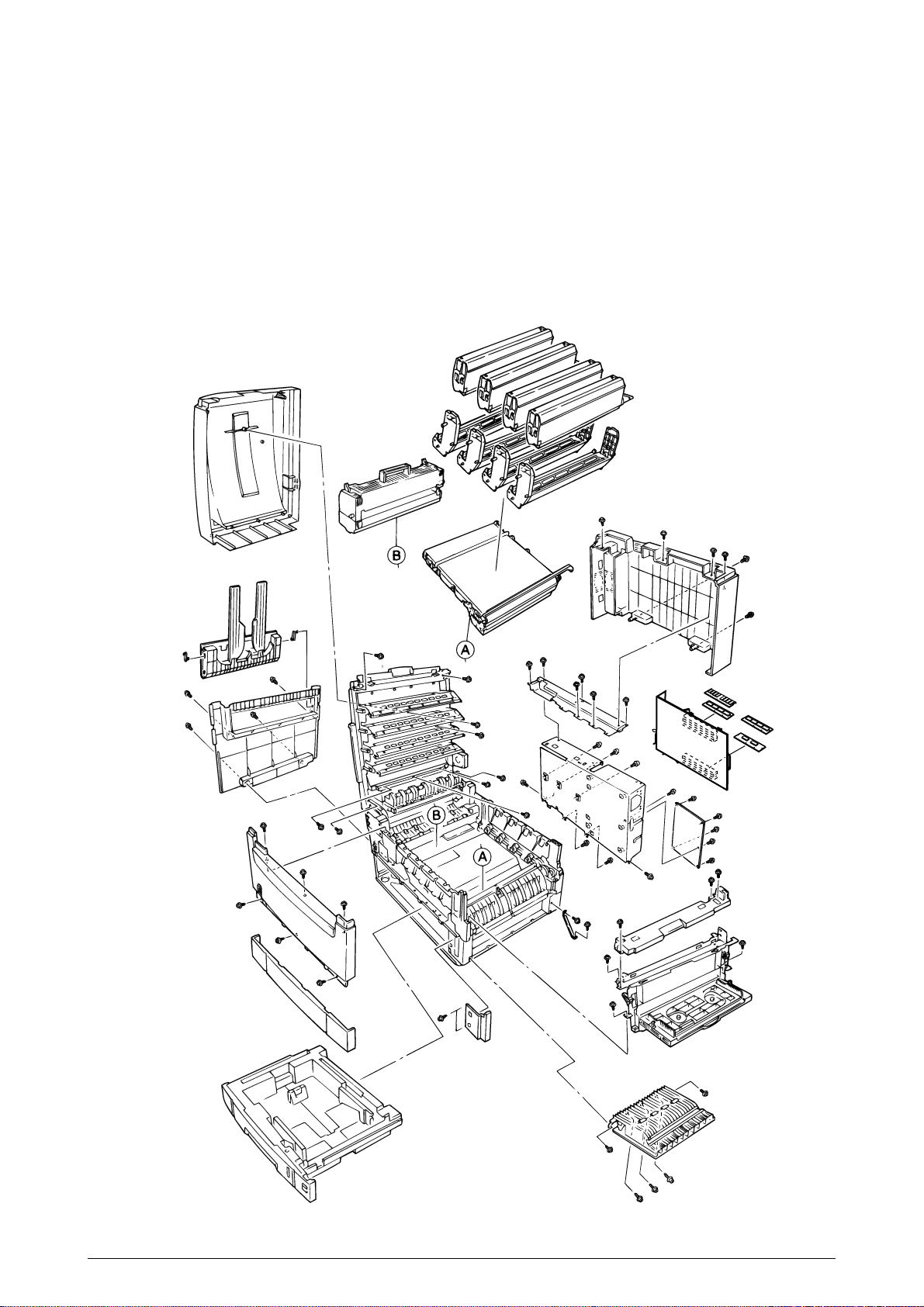
3.2 Parts Layout
Figure 3.1
41388601TH Rev.2 43 /
Page 44

[Top Cover Assy]
Figure 3.2
41388601TH Rev.2 44 /
Page 45

[Printer Unit-1/2]
Figure 3.3
41388601TH Rev.2 45 /
Page 46

[Printer Unit-2/2]
Figure 3.4
41388601TH Rev.2 46 /
Page 47

[Cassette Guide Assy (L), (R)]
Figure 3.5
41388601TH Rev.2 47 /
Page 48

41388601TH Rev.2 48 /
Page 49

[Duplex Unit]
D
C
B
A
D
C
E
B
E
A
Figure 3.6
41388601TH Rev.2 49 /
Page 50

3.3 Replacing Parts
This section describes how to replace the parts and assemblies illustrated below.
41531301 41515110
Print Engine Controller PWB (3.3.22)
41502304 × 4
LED Assy (3.3.2)
40737401
Power-Unit AC-DC Switching (115V) (3.3.34)
40737501
Power-Unit AC-DC Switching (230V) (3.3.34)
40737601
HV Power Supply (3.3.35)
41531402, 41531404
Fuser Unit (3.3.37)
41531502
Belt Unit (3.3.38)
41178202
Duplex Unit (3.3.39)
41480901
Printer NIP
41483001
Printer Unit
41481001
Unit-Lower-Frame (3.3.36)
41500101
Insurator
41483701
Main Cooling Fan Assy (3.3.18)
2381018P0001
HV Tape Harness
41484101
Electrical Chassis (3.3.21)
41483801
Main Motor Assy (3.3.32)
41483902
Belt Motor Assy (3.3.30)
41489001
Plate Assy-Side (3.3.33)
41493002
Multipurpose Tray (3.3.13)
41276502
Rear Cover (3.3.12)
41277402
Left Side Cover (3.3.9)
41481202
Right Side Cover (3.3.7)
41276402
Front Cover (3.3.11)
41277502
Face Up Tray (3.3.10)
41504401
Top Cover
41484402
Top cover (3.3.1)
40866212
Control panel Bezel (3.3.4)
41493002
Multipurpose Tray Assy (3.3.13)
41484902
Cassette Assy (3.3.7)
41277902
Cover-Blind (3.3.7)
41481701
Feed-Roller (3.3.8)
40863801
Plate-Side (3.3.21)
41483102
Printer Chassis (3.3.23)
41483202
Regist Roller Assy (A) (3.3.15)
41483301
Regist Roller Assy (B) (3.3.16)
41483401
Registration Motor Assy (3.3.17)
41187101
Registration Clutch (3.3.17)
41486601
Duplex Guide Assy (3.3.20)
41481301
Main Feed Assy (3.3.36)
41515801
PCE-Size Sence (3.3.36)
22011000P0140
IMSA-9714N-14A (3.3.36)
41490702
Electrical Chassis Cooling Fan
40841402
Fuser Latching Handle (R) (3.3.31)
41628301
Fuser Latching Handle Spring (3.3.31)
40850201
Contact Assy (3.3.33)
41045802 × 2
Link (3.3.13)
41486202
MT Tray Cover Assy (3.3.13)
41278002
MT Top Cover (3.3.13)
40325101
MT Drive Gear (3.3.13)
40841302
Fuser Latching Handle (L) (3.3.29)
41628301
Fuser Latching Handle Spring (3.3.29)
40841601
Entrance Sensor Actuator #1 (3.3.24)
41578501
Entrance Sensor Actuator #2 (3.3.26)
40841801
Entrance Sensor Actuator #3 (3.3.26)
41621801
Registration Shutter Solenoid Assy
41488801
Registration Shutter
41589401
Registration Shutter Spring
41641701
Fuser Driver Gear-A (3.3.27)
41095901
Fuser Exit Roller (3.3.27)
4PP4043-4489P001
Fuser Exit Roller Bushing (L) (3.3.27)
4PP4076-3949P001
Fuser Exit Roller Bushing (R) (3.3.27)
41189701 × 4
Drum Contact Assy (3.3.14)
41258301
Entrance Sensor PWB (3.3.25)
41491001
Color Registration Sensor Assy (3.3.19)
41073601
Exit Sensor Assy (3.3.28)
41483701
Main Motor FAN Assy (3.3.27)
40861001 × 8
LED Assy Spring (3.3.2)
41257902
LED Control PWB (Y71) (3.3.4)
41349801
Stack Full Sensor (3.3.4)
41349301 × 4
Eject Roller (3.3.4)
41484501
Control Panel Assy (3.3.4)
2381005P0015
Control Panel Tape Harness (3.3.4)
41514101
LED Harness K
41514102
LED Harness Y
41514103
LED Harness M
41514104
LED Harness C
41328402
Top Cover Handle (3.3.5)
41277602
Top Cover Latch (3.3.5)
40861401 × 2
Top Cover Latch Spring (3.3.5)
41484701
Eject Guide Assy (3.3.6)
41388601TH Rev.2 50 /
Page 51

3.3.1 Top cover
(1) Open the top cover Assy.
(2) Remove the nine screws 1 to detach the top cover 2.
2
1
1
1
41388601TH Rev.2 51 /
Page 52

3.3.2 LED Assy/ LED Assy spring
(1) Open the top cove 1.
(2) Remove the three cables, and unhook the LED Assy 2 at the two places to demount it (The
two springs 3 become detached together with the LED Assy 2).
(3) Detach the LED connector 4.
When assembling, attach the LED connector 4 to the LED head and insert the flat cable.
1
3
4
3
4
2
41388601TH Rev.2 52 /
Page 53

3.3.3 Top cover unit
(1) Remove the top cover (see section 3.3.1).
(2) Remove the rear cover (see section 3.3.12).
(3) Remove the front cover (see section 3.3.11).
(4) Remove the electrical chassis (see section 3.3.21).
(5) Unscrew the screws 1 and 2 to remove the limiters (F) 3 and (R) 4.
(6) Remove the inner shaft 5, then the top cover unit 8 (The inner springs 6 and 7 become
detached).
8
7
5
2
1
1
4
6
2
3
41388601TH Rev.2 53 /
Page 54

3.3.4 Control panel Assy/ Control panel bezel/ LED control PWB/ Toner sensor/ Stack full sensor/
Control panel tape harness/ Eject roller
(1) Detach the control panel bezel 1.
(2) Remove the screws 2 to demount the control panel 3.
(3) Detach the control panel tape harness 4.
(4) Remove the screws 6, unhook the connector 7 and demount the LED control PWB 8.
(5) Unscrew the screws 9 to remove the plate 0.
(6) Disengage the claw to demount the toner sensor A.
(7) Demount the stacker full sensor B.
(8) Unscrew the eject sensor bracket C, D.
1
2
6
2
7
3
9
C
D
4
8
B
A
9
0
41388601TH Rev.2 54 /
Page 55

3.3.5 Top cover handle/ Top cover latch/ Top cover latch spring
(1) Remove the two screws 1 to detach the top cover handle 2 and disengage the top cover
latch 3 (The two top cover latch springs 4 become detached).
1
1
4
3
2
4
41388601TH Rev.2 55 /
Page 56

3.3.6 Eject guide Assy
(1) Remove the seven screws 1 to detach the eject guide Assy 2.
1
2
1
1
1
41388601TH Rev.2 56 /
Page 57

3.3.7 Cassette Assy/ Blind cover/ Side cover R Assy
(1) Detach the cassette Assy 1.
(2) Disengage the blind cover 2 at the two places to detach it.
(3) Unscrew the two screws to remove the stopper 4.
(4) Disengage the claw on the left support of the side cover R to detach the side cover R.
2
1
5
4
5
5
3
5
41388601TH Rev.2 57 /
Page 58

3.3.8 Feed rollers
(1) Remove the cassette.
(2) Unlatch and demount the feed rollers 1.
1
1
1
41388601TH Rev.2 58 /
Page 59

3.3.9 Left side cover
(1) Remove the four screws 1 to detach the left side cover 2.
2
1
1
41388601TH Rev.2 59 /
Page 60

3.3.10 Face-up tray
(1) Open the face-up tray in the arrow direction and move the links 2 out of engagement (at two
places each of the links) to detach the face-up tray 1.
2
2
1
41388601TH Rev.2 60 /
Page 61

3.3.11 Front cover
(1) Open the top cover 1.
(2) Disengage the claws and remove the blind cover 2.
(3) Unscrew the six screws 4 to detach the front cover 3.
1
4
4
4
4
3
4
2
41388601TH Rev.2 61 /
Page 62

3.3.12 Rear cover
(1) Open the top cover 1,
(2) Remove the five screws 3 and 4 to detach the rear cover 2.
1
4
3
3
2
41388601TH Rev.2 62 /
Page 63

3.3.13 Multipurpose tray Assy/ Multipurpose tray cover Assy/ Links/ Multipurpose tray top cover/
Multipurpose tray drive gear
(1) Remove the rear cover (see section 3.3.12).
(2) Remove the front cover (see section 3.3.11).
(3) Unscrew the three screws 1 to detach the multipurpose tray top cover 2.
(4) Unscrew the two screws 3 and remove the connector to detach the multipurpose tray 4.
(5) Disengage 4 and 5 to detach the multipurpose tray cover Assy 5 (the links 7 become
detached).
(6) Unhook and detach the multipurpose tray drive gear 8.
1
6
3
1
5
Engagement
2
4
6
Engagement
8
3
8
5
41388601TH Rev.2 63 /
Page 64

3.3.14 Drum contact Assys
(1) Insert a flatblade screwdriver between the printer case and the drum contact Assy 1 to
demount the drum contact Assy.
1
41388601TH Rev.2 64 /
Page 65

3.3.15 Registration roller Assy (A)/ Registration drive gear (A)
(1) Remove the front cover (see section 3.3.11).
(2) Remove the rear cover (see section 3.3.12).
(3) Remove the multipurpose tray (see section 3.3.13).
(4) Unscrew the four screws 1 to demount the registration roller Assy (A) 2.
(5) Remove the E ring 3 to detach the registration gear (A) 4.
2
1
1
4
3
41388601TH Rev.2 65 /
Page 66

3.3.16 Registration roller Assy (B)
(1) Remove the cassette Assy.
(2) Remove the front cover (see section 3.3.11).
(3) Remove the rear cover (see section 3.3.12).
(4) Remove the electrical chassis (see section 3.3.21).
(5) Remove the registration clutch (see section 3.3.17).
(6) Remove the printer chassis (see section 3.3.23).
(7) Unscrew the four screws and pull out the registration Assy (B) 2 in the arrow direction.
1
2
1
1
41388601TH Rev.2 66 /
Page 67

3.3.17 Registration clutch, Registration motor Assy
(1) Remove the left side cover (see section 3.3.9).
(2) Remove the electrical chassis (see section 3.3.21).
(3) Remove the connector and the E ring 1, then screws 3 and 4, and then the earth plate 5.
(4) Remove the connector and unscrew the two screws 6 to demount the registration motor Assy
7.
7
6
3
2
5
4
6
1
41388601TH Rev.2 67 /
Page 68

3.3.18 Cooling fan
(1) Unhook the connector 1, and remove the screws 2 and the cooling fan 3.
1
3
air direction
2
41388601TH Rev.2 68 /
Page 69

3.3.19 Color registration sensor Assy
(1) Remove the two screws 1 and the three connectors to demount the color registration sensor
Assy 2.
(2) Remove the earth plate B 3.
1
1
2
3
1
2
4
41388601TH Rev.2 69 /
Page 70

3.3.20 Duplex guide Assy
(1) Unlatch and demount the duplex guide Assy 1.
(2) Remove the springs 2.
1
2
2
Main chassis (L side)
41388601TH Rev.2 70 /
Page 71

3.3.21 Electrical chassis/ Electrical chassis cooling fan
(1) Unscrew the five screws 1 and two screws 2 to remove the plate A 3.
(2) Unscrew the thirty-one screws 4 to remove the shield plate B 5.
(3) Remove the printer engine controller PWB (see section 3.3.22).
(4) Unscrew the eleven screws 6 to detach the electrical chassis 7.
(5) Unscrew the two screws 8 to demount the electrical chassis cooling fan 9.
1
1
8
9
1
7
air direction
2
3
6
6
6
6
4
6
5
4
41388601TH Rev.2 71 /
Page 72

1
3.3.22 Printer engine controller PWB
(1) Remove the rear cover (see section 3.3.12).
(2) Remove the electrical chassis and the electrical cooling fan (see section 3.3.21).
(3) Remove the five screws 1 and all the connectors to demount the printer engine controller
PWB 2.
2
1
41388601TH Rev.2 72 /
Page 73

3.3.23 Printer unit chassis
(1) Unscrew the screw 1 and remove the AC switch Assy 2.
(2) Remove the four black screws 3 and six screws 4 to detach the printer unit chassis 5.
3
1
2
3
4
3
4
4
5
4
4
3
3
41388601TH Rev.2 73 /
Page 74

3.3.24 Entrance cassette sensor actuator
(1) Remove the printer unit chassis (see section 3.3.23).
(2) Turn over the main chassis.
(3) Remove the two clamps with tweezers to demount the entrance cassette sensor actuator 1.
1
Main chassis
41388601TH Rev.2 74 /
Page 75

3.3.25 Entrance sensor PWB
(1) Remove the registration roller Assy (B) (see section 3.3.16).
(2) Remove the two screws 1 to demount the entrance sensor PWB 2.
1
2
41388601TH Rev.2 75 /
Page 76

3.3.26 Entrance MT sensor actuator and Entrance belt sensor actuator
(1) Remove the entrance sensor PWB (R71) (see section 3.3.25).
(2) Unlatch and detach the entrance MT sensor actuator 1.
(3) Unlatch and detach the entrance belt actuator 2.
2
1
41388601TH Rev.2 76 /
Page 77

3.3.27 Main motor fan/ Fuser eject roller
(1) Unscrew the two screws 1 to remove the fan Assy 2.
(2) Unscrew the fuser eject roller contact 4.
(3) Remove the fuser drive gear 5.
(4) Unscrew the fuser drive gear Assy 8.
(5) Remove the screws and washers 0 to demount the fan A.
(6) Unlatch and detach the fuser eject roller bearing (L) B and fuser eject roller C.
9
0
A
C
9
0
B
5
3
4
8
2
7
1
1
41388601TH Rev.2 77 /
Page 78

3.3.28 Eject sensor Assy
(1) Remove the fuser eject roller (see section 3.3.27).
(2) Remove the screw 1 and connector 2 to demount the (red/blue) eject sensor Assy 2.
1
2
41388601TH Rev.2 78 /
Page 79

3.3.29 Fuser latching handle (L)
(1) Remove the latching handle spring 1.
(2) Unscrew the fuser latching handle (L) 3.
3
1
2
41388601TH Rev.2 79 /
Page 80

3.3.30 Belt motor Assy
(1) Remove the fuser latching handle (R) (see section 3.3.32).
(2) Unscrew the two screws 1 to detach the two connector 2.
(3) Demount the belt motor Assy 3.
2
1
1
3
41388601TH Rev.2 80 /
Page 81

3.3.31 Fuser latching handle (R)
(1) Remove the printer unit chassis (see section 3.3.23).
(2) Remove the E ring 1.
(3) Remove the fuser latching handle spring 2 to detach the fuser latching handle (R) 3.
3
1
2
41388601TH Rev.2 81 /
Page 82

3.3.32 Main motor Assy
(1) Remove the belt motor Assy (see section 3.3.30).
(2) Remove all the connectors.
(3) Remove the two screws 1 to demount the main motor Assy 2.
1
1
2
41388601TH Rev.2 82 /
Page 83

3.3.33 Contact Assy/ Side plate Assy
(1) Remove the printer unit chassis (see section 3.3.23).
(2) Remove the four screws 1 to detach the side plate Assy 2.
(3) Remove the three screws 3 to detach the contact Assy 4.
1
2
3
4
41388601TH Rev.2 83 /
Page 84

3.3.34 Low voltage power supply
(1) Remove the printer unit chassis (see section 3.3.23).
(2) Unhook the connector 1.
(3) Remove the eight screws 2 to demount the low voltage power supply 5.
0
2
0
1
0
2
2
7
8
6
3
5
B
A
9
41388601TH Rev.2 84 /
Page 85

3.3.35 High voltage power supply
(1) Remove the contact Assy (see section 3.3.33).
(2) Unhook the connector of the high voltage power supply 2.
(3) Remove the two screws 1 to detach the high voltage power supply 2 and the tape harness
3.
1
3
1
2
41388601TH Rev.2 85 /
Page 86

3.3.36 Main feed Assy
(1) Remove the printer unit chassis (see section 3.3.23).
(2) Remove the low voltage power supply and high voltage power supply (see sections 3.3.34
and 3.3.35).
(3) Unscrew the five screws 1 to remove the lower plate 2.
(4) Unscrew the six screws 3 to demount the main feed Assy 4.
(5) Unscrew the screws 5 to detach the cable and then the PCB size board 6.
(6) Unscrew the screw 7 to detach the duplex connector 8.
(7) Unscrew the screws 9 to detach the second tray connector 0.
8
1
1
2
5
7
6
9
0
4
3
3
41388601TH Rev.2 86 /
Page 87

3.3.37 Fuser unit
(1) Open the top cover 1.
(2) Push the right and left fuser levers (blue) 2 in the arrow direction to detach the fuser unit 3.
3
2
41388601TH Rev.2 87 /
Page 88

3.3.38 Belt unit
(1) Open the top cover 1.
(2) Remove the I/D unit.
(3) Push the lever (blue) 2 in the arrow direction, raise the handle (blue) and detach the belt unit
3.
1
3
2
41388601TH Rev.2 88 /
Page 89

3.3.39 Duplex unit
(1) Remove the cassette Assy, the front cover and the front cover inner buffle.
(2) Unlatch the rear at the right and left and pull the duplex unit 1 toward the front.
4
5
2
3
1
41388601TH Rev.2 89 /
Page 90

3.3.40 CU Assy
(1) Pulling out Control Board
1. Loosen the two screws 1.
2. Pull the control board 2 out.
3. Place the control board 2 on a flat table.
(2) Detaching Fan
1. Remove the connector 3.
2. Remove the two screws 4.
3. Detach the fan 5.
2
1
1
4
5
3
41388601TH Rev.2 90 /
Page 91

(3) Demounting CRM Board
1. Remove the three screws 6 to detach the fan bracket 7.
2. Remove the four screws 8 to detach the plate support 9 and the guide rail 0.
3. Remove the two screws A to detach the guide rail B.
4. Remove the two screws C and three screws D, then demount the CRM board E.
6
7
8
6
9
E
A
B
9
8
D
0
8
D
8
0
A
C
8
41388601TH Rev.2 91 /
Page 92

4. ADJUSTMENT
Adjustments are carried out by key operations on the operator panel.
The maintenance menu is included in the general menu of this printer. Choose the maintenance
menu for adjustment.
4.1 Maintenance Menu and Its Functions
The general menu has the category, MAINTENANCE MENU.
The items adjustable in this menu are shown below.
Maintenance Menu
Category
MAINTENANCE MENU
Item(1st Line)
Power Save Mode
Normal Paper Black
Setting
Normal Paper Color
Setting
Value(2nd Line)
Enabled
Disabled
0
+1
+2
-2
-1
0
+1
+2
-2
-1
DF
Sets the Power Save Mode
*
enabled/disabled. The shift time to
enable the Power Save mode can
be changed according to the
POWER SAVE SHIFT TIME item of
SYSTEM CONFIG MENU.
Implements fine adjustment of
*
BLACK printing on normal paper
when unclear characters or spots
are often found on print results.
With dispersed or snowed printing
in the part at high-density, decrease
the value. With unclear printing,
increase the value.
Implements fine adjustment of
*
COLOR printing on normal paper
when unclear characters or spots
are often found on the print result.
With dispersed or snowed printing
in the part at high-density, decrease
the value. With unclear printing,
increase the value.
Functions
Transparency Black
Setting
Transparency Color
Setting
41388601TH Rev.2 92 /
0
+1
+2
-2
-1
0
+1
+2
-2
-1
Implements fine adjustment of
*
BLACK printing on Transparency
when unclear characters or spots
are often found on the print result.
With dispersed or snowed printing
in the part at high-density, decrease
the value. With unclear printing,
increase the value.
Implements fine adjustment of
*
COLOR printing on Transparency
when unclear characters or spots
are often found on the print result.
With dispersed or snowed printing
in the part at high-density, decrease
the value. With unclear printing,
increase the value.
Page 93

4.2 Short Plug Settings
The CRM board has five short plugs that can be set as follows:
Short Plug (WE1,3, 5 and 7)
Sets flash ROM DIMM to connect WE signals.
(1-2 Short: Disconnects WE signals; 2-3 Short: Connects WE signals.)
The factory-shipped short plug is set to the 2-3 short: Re-programmable the Flash ROM DIMM.
Short Plug (DIMM2)
Sets the banks of ROM DIMM Slot B.
(1-2 Short: For 1-Bank DIMM; 2-3 Short: For 2-Bank DIMM)
1-bank DIMM (dual-sided 1 bank) is only a prototype and does not exist in production-run
printers.
4.3 Printing Singly Using Controller-Equipped Printer
Menu Map Printing
Prints the program versions, controller block, and other printer configuration and settings.
Operation: (Press of Switch)
Without HDD: “0” → “3” → “3”
With HDD: “0” → “0” → “3” → “3”
File List Printing
Prints a list of files stored on a HDD or in ROM.
Operation: (Press of Switch)
Without HDD: “0” → “3” → “1” → “3”
With HDD: “0” → “0” → “3” → “1” → “3”
Font List Printing (PCL)
Prints a list of PCL fonts.
Operation: (Press of Switch)
Without HDD: “0” → “3” → “1” → “1” → “3”
With HDD: “0” → “0” → “3” → “1” → “1” → “3”
Font List Printing (PS)
Prints a list of PS fonts.
Operation: (Press of Switch)
Without HDD: “0” → “3” → “1” → “1” → “1” → “3”
With HDD: “0” → “0” → “3” → “1” → “1” → “1” → “3”
Demo Printing
Prints the demo patterns for destinations.
Operation: (Press of Switch)
Without HDD: “0” → “3” → “1” → “1” → “1” → “1” → “3”
With HDD: “0” → “0” → “3” → “1” → “1” → “1” → “1” → “3”
Ethernet Board Self-Diagnostic Printing
When equipped with an Ethernet board, the printer runs diagnostic checks on itself by holding
the SW on the Ethernet board down for two seconds or more, and prints the results.
41388601TH Rev.2 93 /
Page 94

4.4 Adjustment after Part Replacement
Adjustment to be implemented after each part replacement is described below.
Adjustment and correction of color registration are always required for each part replacement.
Replaced Part
LED Head
Drum Cartridge (Y, M, C, K)
Fuser Unit
Belt Cassette Assy
PU (K73 Board)
*
Note:
When the EEPROM of the PU (K73 Board) is replaced to a new one, color balance must be
adjusted.
Adjustment
Color balance adjustment
Not required.
Not required.
Not required.
Re-mounting the EEPROM used prior to the replacement *Note
41388601TH Rev.2 94 /
Page 95

4.5 Color Balance Adjustment
Color balance has been adjusted appropriately when a printer is shipped from the plant. However,
it may be out of the appropriate balance during use. In such a case, color balance should be
modified.
Note:
Density of each color depends on each other. Therefore, adjustment must be repeated
several times to reach the correct color balance.
(1) Set letter paper in the tray specified on the operator panel.
(2) Press
(3) Press
(4) Press
(5) Press
(6) Choose the number of the color closest to the [(] part on the test pattern.
(7) Press
(8) Press
(9) Repeat the steps (6)~(8) to approximate the color at the [(] part on the test pattern to [00]
(10)Press
))
) several times to display [COLOR MENU].
))
11
55
1 or
5 to display [COLOR BALANCE CORRECTION/PATTERN PRINT].
11
55
33
3 to start test printing.
33
11
1 to display [COLOR BALANCE CORRECTION/RESET].
11
If the selected color is [00], the color balance is correct and no adjustment is required.
If it is not [00], the color balance should be adjusted in the procedures below.
22
66
2 or
6 several times to display the value selected in Step (6).
22
66
33
3 to start test printing.
33
as much as possible.
44
4 to display [ON LINE].
44
41388601TH Rev.2 95 /
Page 96

41388601TH Rev.2 96 /
Page 97

4.6 EEPROM Replacement after CRM Board and K73 Board Replacement
When replacing the CRM Board or K73 Board, the EEPROM must be removed and re-mounted
on the new board (to deliver the user setting and font installation information to the new board).
If the EEPROM used by the user is broken and not suitable for further use, the EEPROM on the
new board may be used.
41388601TH Rev.2 97 /
Page 98

5. REGULAR MAINTENANCE
5.1 Consumables to be Regulary Replaced
It is recommended that a user should replace the consumables below according to the
replacement standard. (If not replaced, print quality is not assured or it may result in a failure.)
Part Name
Large-capacity
Toner Cartridge
ID Cartridge
Fuser Unit
Belt Unit
The above consumables replacement may be performed by a user.
5.2 Cleaning
The inside and outside of this printer should be cleaned with a hand vacuum cleaner, if necessary.
Note:
Do not touch the Image drum terminal, LED lens array and LED head connectors.
Time for Replacement
When the message “Toner Low”
is displayed.
When the message “Drum Life”
is displayed.
When the message “Fuser Life”
is displayed.
When the message “Belt Life” is
displayed.
Replacement Condition
After 15,000 copies have
been printed.
After 26,000 copies have
been printed. (at 3P/J)
After 80,000 copies have
been printed.
After 80,000 copies have
been printed. (at 3P/J)
Adjustment after Replacement
Replace the Toner cartridge.
Reset the drum counter
after drum replacement.
Reset the fuser counter.
Reset the belt counter.
5.3 Cleaning of LED Lens Array
When a longitudinal white band or stripes (that is, void or light printing) appear on a printed paper
surface, the LED lens array should be cleaned.
Note:
The LED head cleaner must be used to clean the LED lens array. (The LED head cleaner
is included in the Toner cartridge box.)
White band, white stripes
(Void or light printing)
5.4 Cleaning of Pick-up Roller
When papers are not fed normally, the Pick-up roller should be cleaned.
Note:
Clean it with a soft cloth and alcohol. Be cautious not to damage the roller surface.
41388601TH Rev.2 98 /
Page 99

6. TROUBLESHOOTING PROCEDURES
6.1 Tips for Troubleshooting
(1) Check the basic check points covered in the user’s manual.
(2) Gather as much information on the problem from the customer as possible.
(3) Perform inspections in conditions close to those in which the problem had occurred.
6.2 Check Points before Correcting Image Problems
(1) Is the printer being run in proper ambient conditions?
(2) Have the consumables toner and image drum cartridges been replaced properly?
(3) Is the paper normal? See paper specifications section.
(4) Has the image drum cartridge been loaded properly?
6.3 Tips for Correcting Image Problems
(1) Do not touch, or bring foreign matter into contact with the image drum surface.
(2) Do not expose the image drum to direct sunlight.
(3) Keep hands off the fuser unit as it is heated during operation.
(4) Do not expose the image drum to light for longer than 3 minutes at room temperature.
41388601TH Rev.2 99 /
Page 100

6.4 Preparation for Troubleshooting
(1) Operator panel display
The failure status of this printer is indicated on the LCD (liquid crystal display) of the Operator
panel.
Take the proper corrective action according to the message displayed on the LCD.
6.5 Troubleshooting Flow
If a problem should develop in this printer, troubleshoot in the following procedure.
Problem
Problem that results
in LCD message
indication
Image problem
(and a problem that
does not result in LCD
message indication.)
Troubleshoot based on the
LED message list.
See 6.5.1.
Perform troubleshooting
with the troubleshooting
flow chart. See 6.5.2.
Perform troubleshooting
with the troubleshooting
flow chart. See 6.5.3.
41388601TH Rev.2 100 /
 Loading...