

1277-9813 Rev 2
Sony Mobile Communications AB – Company Internal
Working Instructions
- mechanical -
Xperia Z1
TM
C6902, C6903, C6906, L39h

Sony Mobile Communications AB – Company Internal
2(82)
Working Instruction (mech)
CONTENTS
1 Exterior Views ................................................................................. 5
1.1 C6902, C6903, C6906, L39h ................................................................. 5
2 Tools ................................................................................................ 6
3 Disassembly.................................................................................... 8
3.1 Window Back and Sheet Battery ......................................................... 8
3.2 Rear Cover Assy ................................................................................ 10
3.3 Camera ................................................................................................ 12
3.4 Shield Camera .................................................................................... 12
3.5 SIM Tray .............................................................................................. 13
3.6 Battery ................................................................................................. 13
3.7 Main PBA ............................................................................................ 14
3.8 Loudspeaker Holder ........................................................................... 16
3.9 RF Cable A .......................................................................................... 17
3.10 Main Frame Assy and Front Cover ................................................... 17
4 Replacement ................................................................................. 19
4.1 Window Back ...................................................................................... 19
4.2 Sheet Battery ...................................................................................... 19
4.3 Rear Cover Assy ................................................................................ 19
4.4 Camera ................................................................................................ 19
4.5 Shield Camera .................................................................................... 20
4.6 SIM Tray .............................................................................................. 20
4.7 Battery ................................................................................................. 20
4.8 Loudspeaker Holder ........................................................................... 20
4.9 RF Cable A .......................................................................................... 21
4.10 Main Fr ame Assy ................................................................................ 21
4.11 Adhesive Earspeaker ......................................................................... 22
4.12 Adhesive FPC Relay Bottom ............................................................. 23
4.13 Adhesive WP Audio Jack .................................................................. 24
4.14 Adhesive WP Camera Key ................................................................. 25
4.15 Adhesive WP Cover Rear .................................................................. 26
4.16 Adhesive WP Loudspeaker ............................................................... 27
4.17 Adhesive WP Main Frame Assy ........................................................ 28
4.18 Adhesive WP Side Key ...................................................................... 30
4.19 Adhesive WP Window Back .............................................................. 31
4.20 BT + WLAN Flex Antenna .................................................................. 33
4.21 Camera Holder .................................................................................... 34
4.22 Camera Key ........................................................................................ 35
4.23 Chat Camera ....................................................................................... 36
4.24 Chat Camera Holder ........................................................................... 37
1277-9813 Rev 2

Sony Mobile Communications AB – Company Internal
3(82)
Working Instruction (mech)
4.25 Core Unit Label ................................................................................... 38
4.26 Cushion 1st Mic ................................................................................... 39
4.27 Cushion 2nd Mic .................................................................................. 40
4.28 Ear Speaker ........................................................................................ 41
4.29 FPC Assembly Audio Jack ................................................................ 42
4.30 FPC Assembly Charger ..................................................................... 43
4.31 FPC Assembly Mic ............................................................................. 44
4.32 FPC Assembly Relay .......................................................................... 45
4.33 Front Cover ......................................................................................... 46
4.34 Gasket Charger .................................................................................. 47
4.35 Gasket Side Key ................................................................................. 48
4.36 Holder Magnetic Charger Connector ................................................ 49
4.37 Liquid indicator .................................................................................. 50
4.38 Loudspeaker ....................................................................................... 51
4.39 Magnetic charger connector ............................................................. 52
4.40 PBA Cellular Sub ................................................................................ 53
4.41 PBA WLAN Sub .................................................................................. 54
4.42 Plate Contact RF A ............................................................................. 55
4.43 Power Key ........................................................................................... 56
4.44 RF Cable B .......................................................................................... 57
4.45 SD Cap ................................................................................................ 58
4.46 Sheet Conductive Charger FPC ........................................................ 59
4.47 Sheet Conductive Relay FPC ............................................................ 60
4.48 Sheet Thermal A ................................................................................. 61
4.49 Sheet Thermal B ................................................................................. 62
4.50 Sheet WP 2nd Mic ................................................................................ 63
4.51 Sheet WP Check ................................................................................. 64
4.52 SIM Cap ............................................................................................... 65
4.53 Speaker Panel ..................................................................................... 66
4.54 Tray Core Unit Label .......................................................................... 67
4.55 USB Cap .............................................................................................. 68
4.56 USB Holder ......................................................................................... 69
4.57 Vibrator ............................................................................................... 70
4.58 Volume Key ........................................................................................ 71
4.59 Board Swap - Replacement ............................................................... 72
5 Re-Assembly ................................................................................. 73
5.1 Front Cover and Main Frame Assy ................................................... 73
5.2 RF Cable A .......................................................................................... 74
5.3 Loudspeaker Holder ........................................................................... 74
5.4 Main PBA ............................................................................................ 75
5.5 Battery ................................................................................................. 76
1277-9813 Rev 2

Sony Mobile Communications AB – Company Internal
4(82)
Working Instruction (mech)
5.6 SIM Tray .............................................................................................. 76
5.7 Shield Camera .................................................................................... 77
5.8 Camera ................................................................................................ 77
5.9 Rear Cover Assy ................................................................................ 78
5.10 Sheet Battery ...................................................................................... 80
5.11 Window Back ...................................................................................... 80
6 Revision History ........................................................................... 82
For general information about mechanical repair related issues, refer to
1220-1333: Generic Repair Manual - mechanical
1277-9813 Rev 2
Sony Mobile Communications AB – Company Internal
5(82)
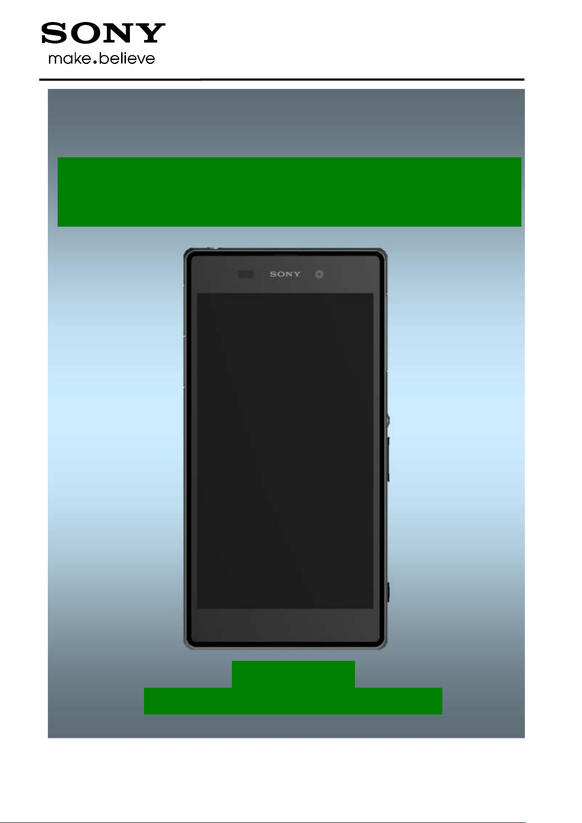
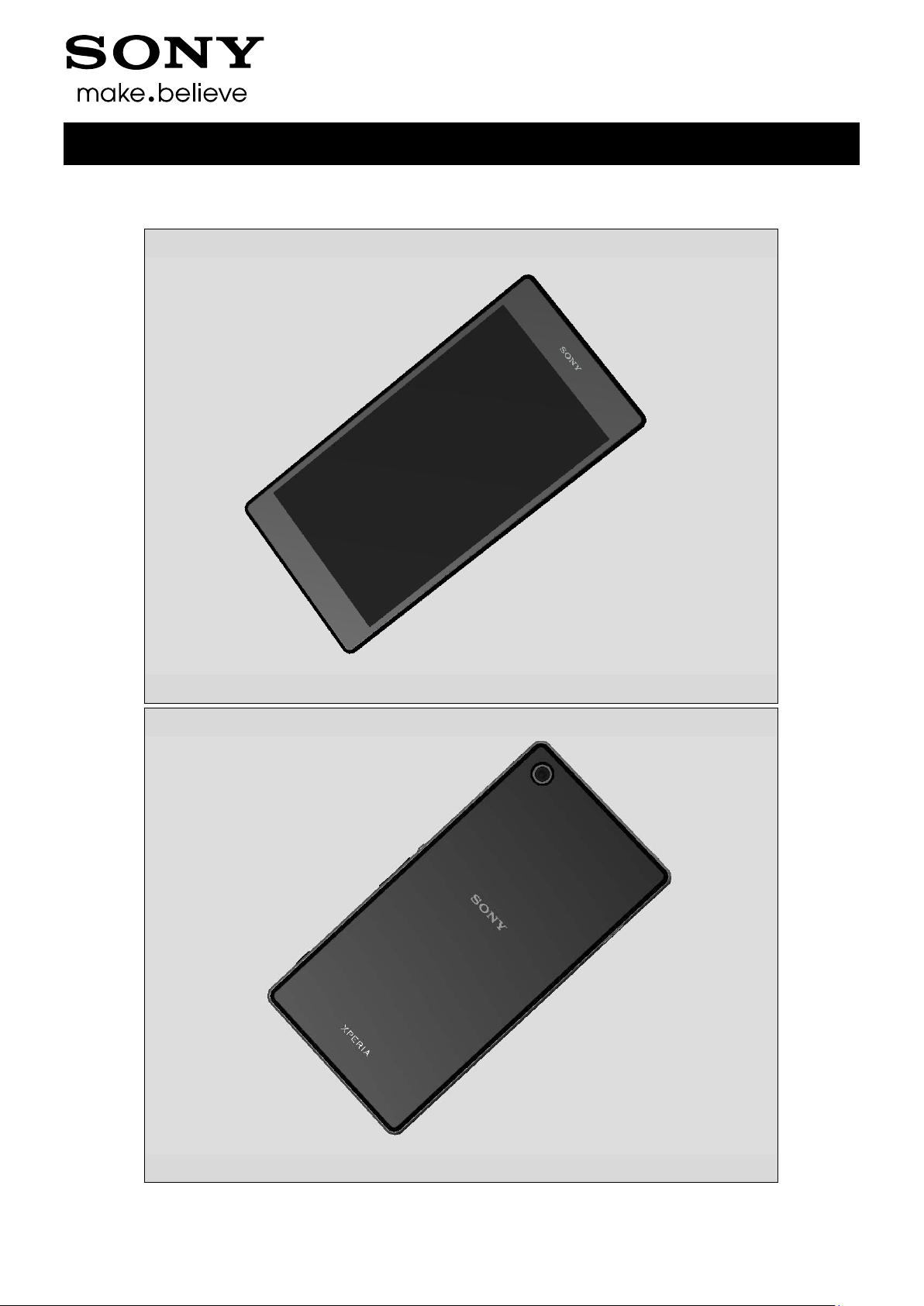
1 Exterior Views
1.1 C69 02, C6903, C6906, L39h
Working Instruction (mech)
1277-9813 Rev 2
Sony Mobile Communications AB – Company Internal
6(82)
2 Tools
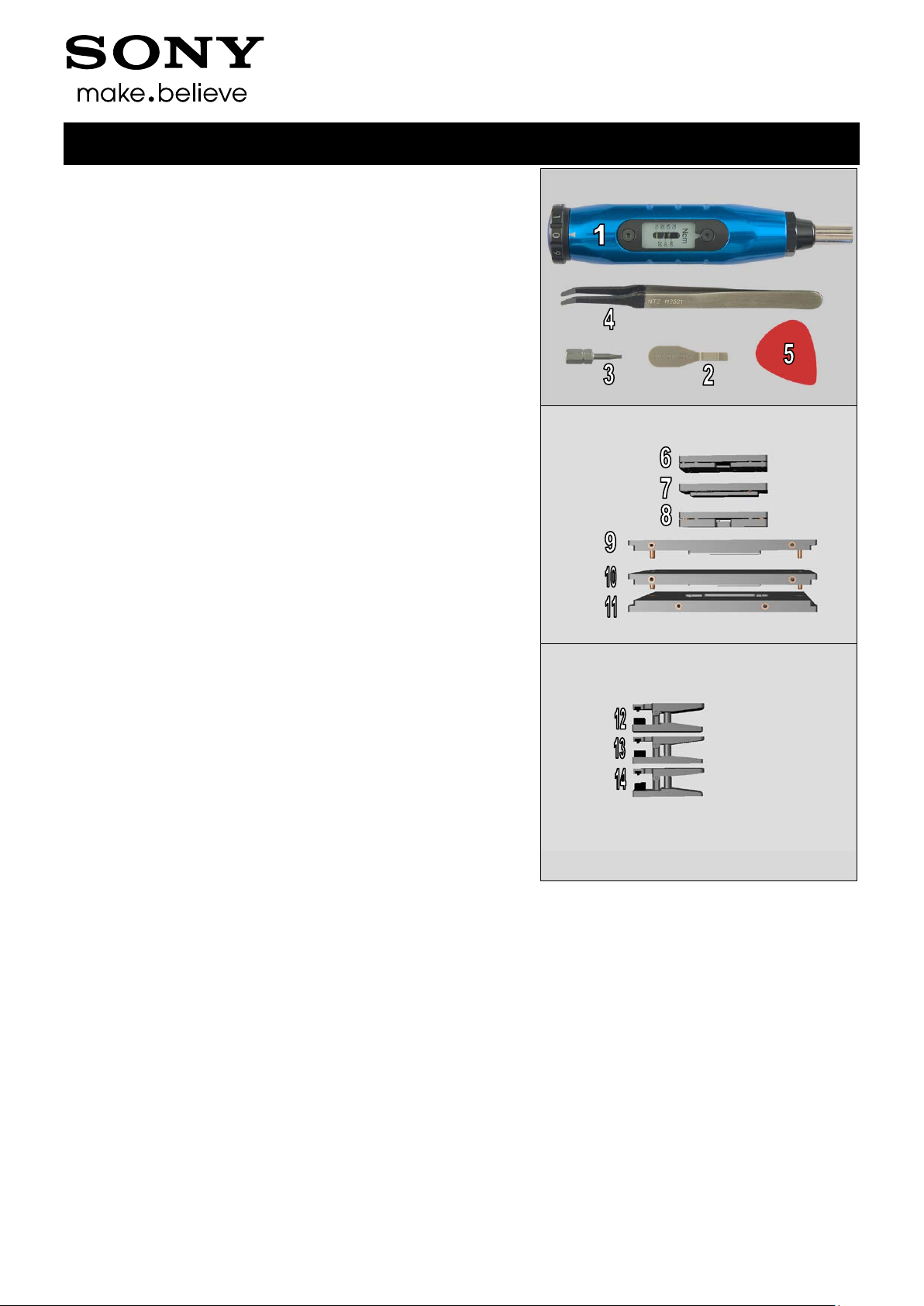
SPECIAL TOOLS
1. Torque Screwdriver
2. Front Opening Tool
3. Torx Bits T4
4. Flex Film Assembly Tool
5. Guitar Pic k
6. Front Cover Adhesive fixture
7. Rear Cover Adhesive fixture
8. Window Back Adhesive fixture
9. Rear Cover Press Inlay
10. Window Back Press Inlay
11. Bottom Press Inlay
Working Instruction (mech)
12. Press Tool Earspeaker
13. Press Tool Loudspeaker
14.Audio Jack press
1277-9813 Rev 2
Sony Mobile Communications AB – Company Internal
7(82)
Tools
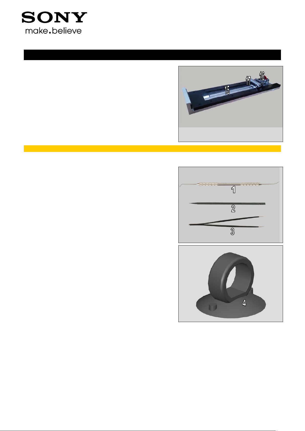
15. Side Panel press
16. Side Panel Press Head
17. Charge connector press pad
For part not on the tools above, refer to the ‘Tools Catalogue/Matrix’!
Working Instruction (mech)
ST ANDARD TOOLS
1. Dentist Hook
2. Nylon Pointer
3. Tweezer
4. Suction cup
1277-9813 Rev 2
Sony Mobile Communications AB – Company Internal
8(82)
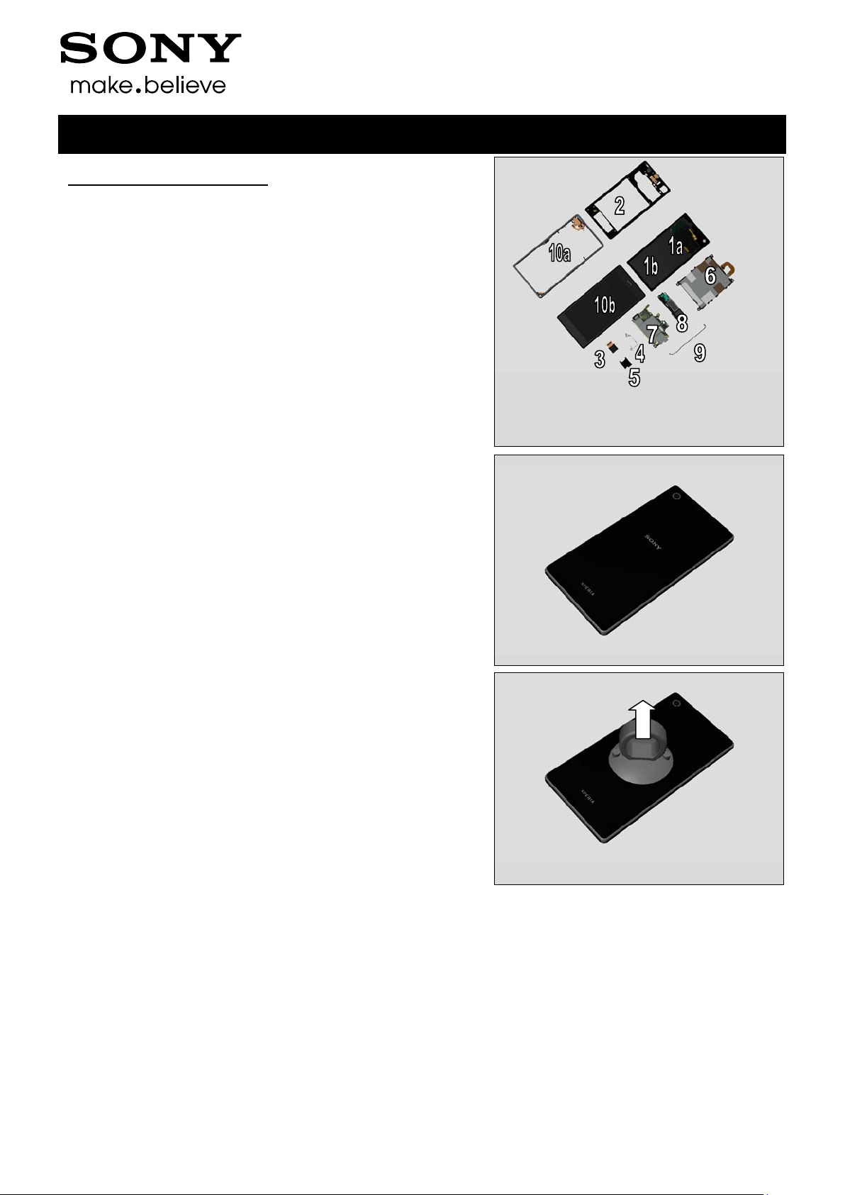
3 Disassembly
C6902, C6903, C6906, L39h
The Disassembly is done to the following modules:
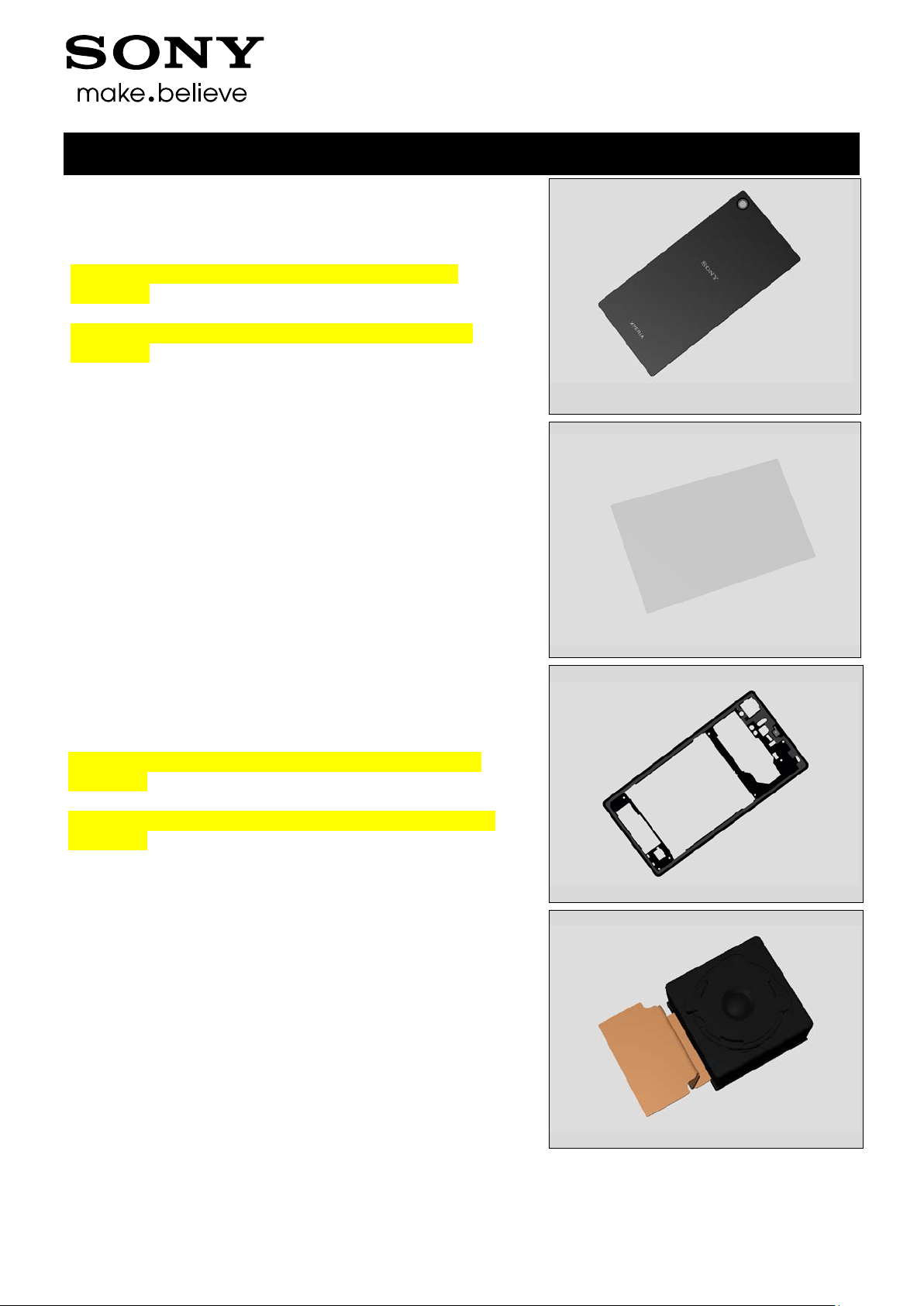
1. Window Back (a) and Sheet Battery (b)
2. Rear Cover Assy
3. Camera
4. Shield Camera
5. SIM Tray
6. Battery
7. Main PBA
8. Loudspeaker Holder
9. RF Cable A
10. Main Frame Assy (a) and Front Cover (b)
Working Instruction (mech)
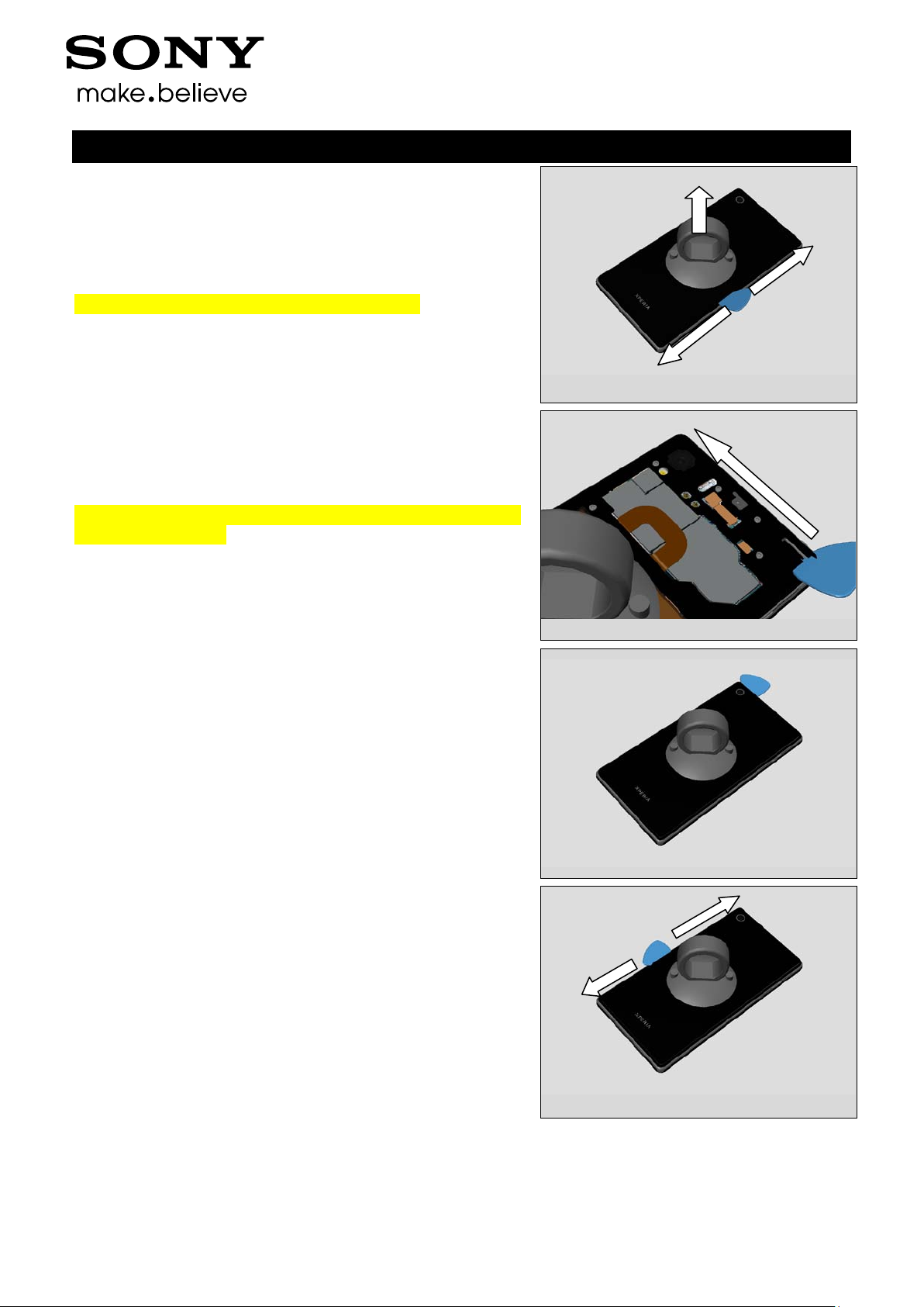
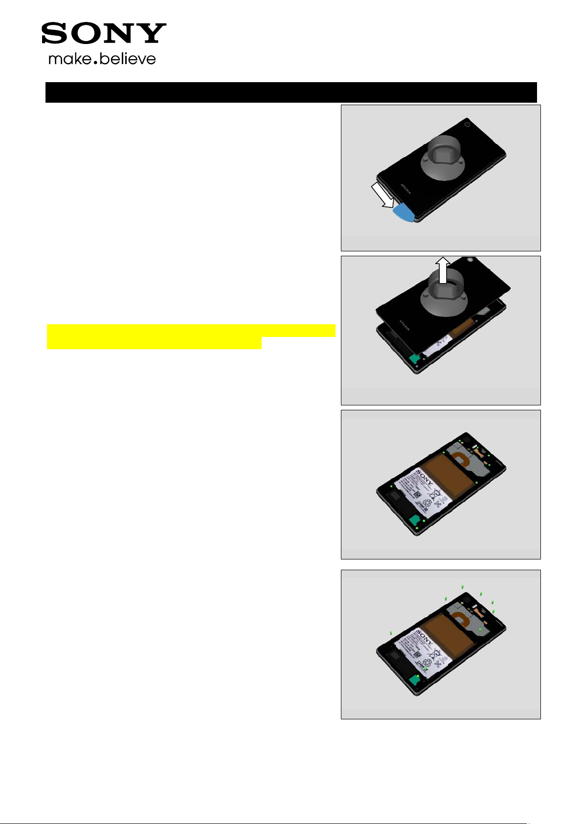
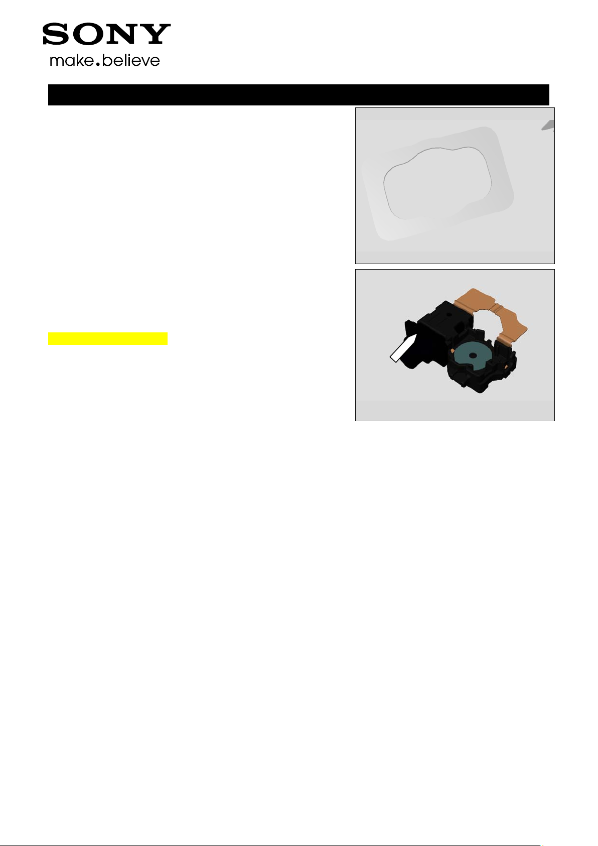
3.1 Window Back and Sheet Battery
Use Suction cup to get space for inserting the Guitar Pick.
1277-9813 Rev 2
Sony Mobile Communications AB – Company Internal
9(82)
Disassembly
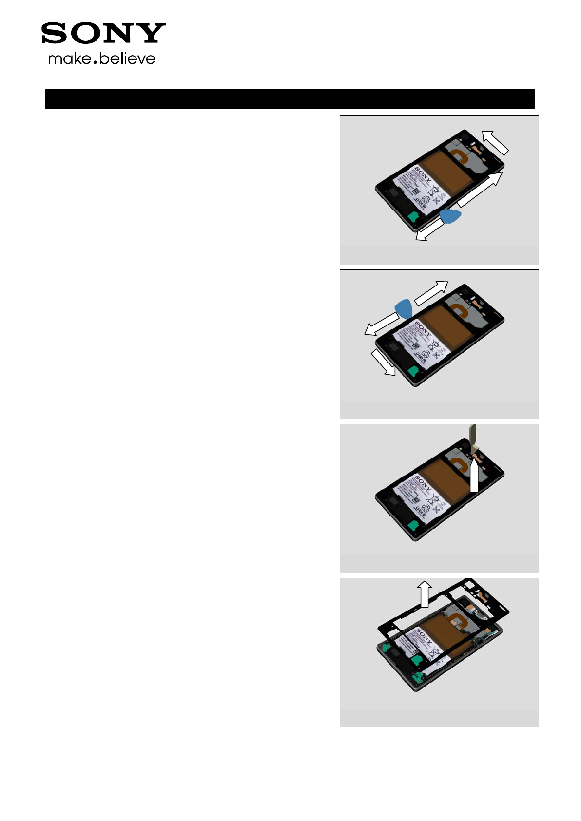
Gently slide the Guitar Pick along to release all sides of the
Back Panel Assy.
Note! Start in the middle of the right long side!
Note! Be careful not to damage flexes when using plectrum
on the top of phone!
Working Instruction (mech)
1277-9813 Rev 2
Sony Mobile Communications AB – Company Internal
10(82)
Disassembly
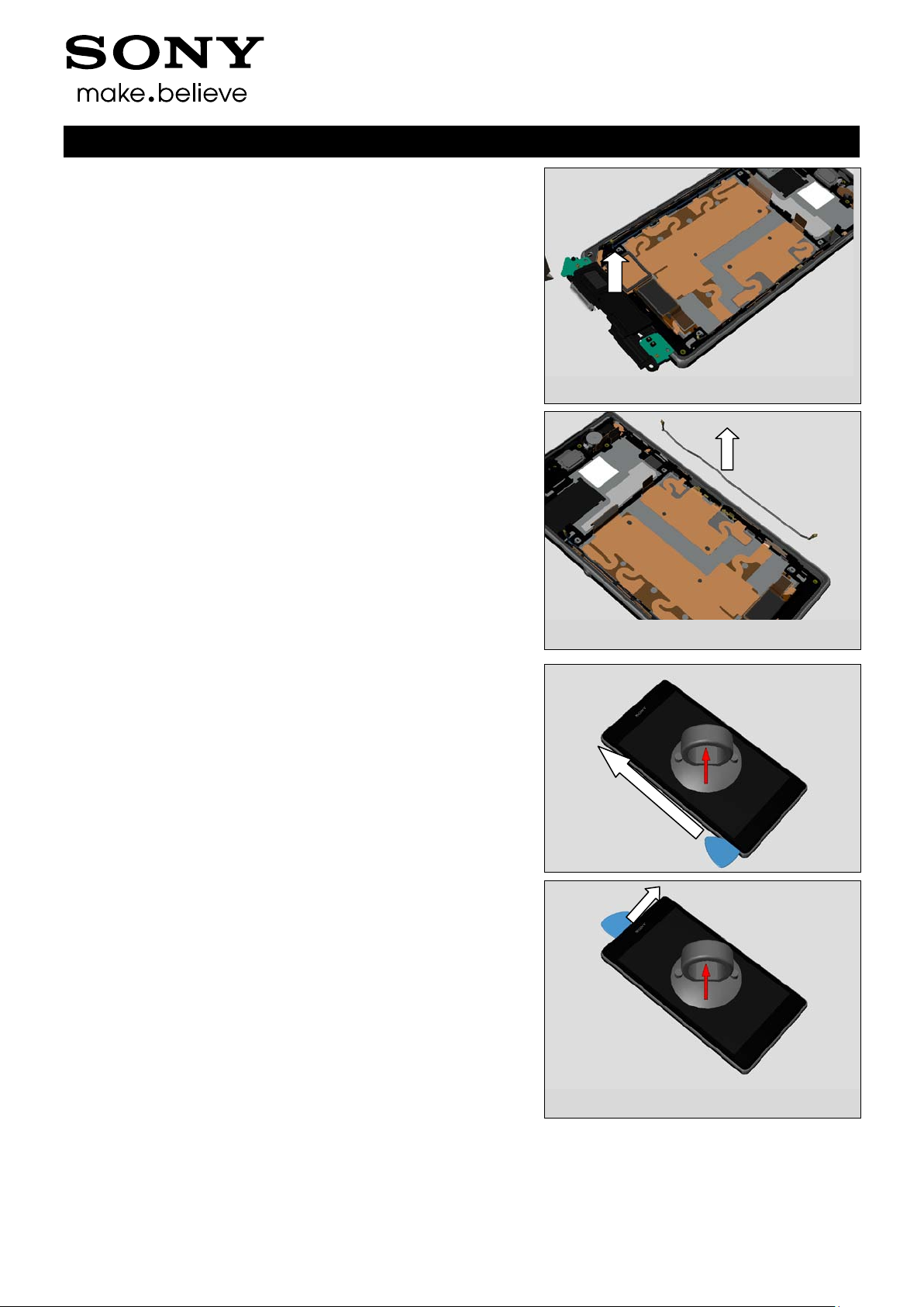
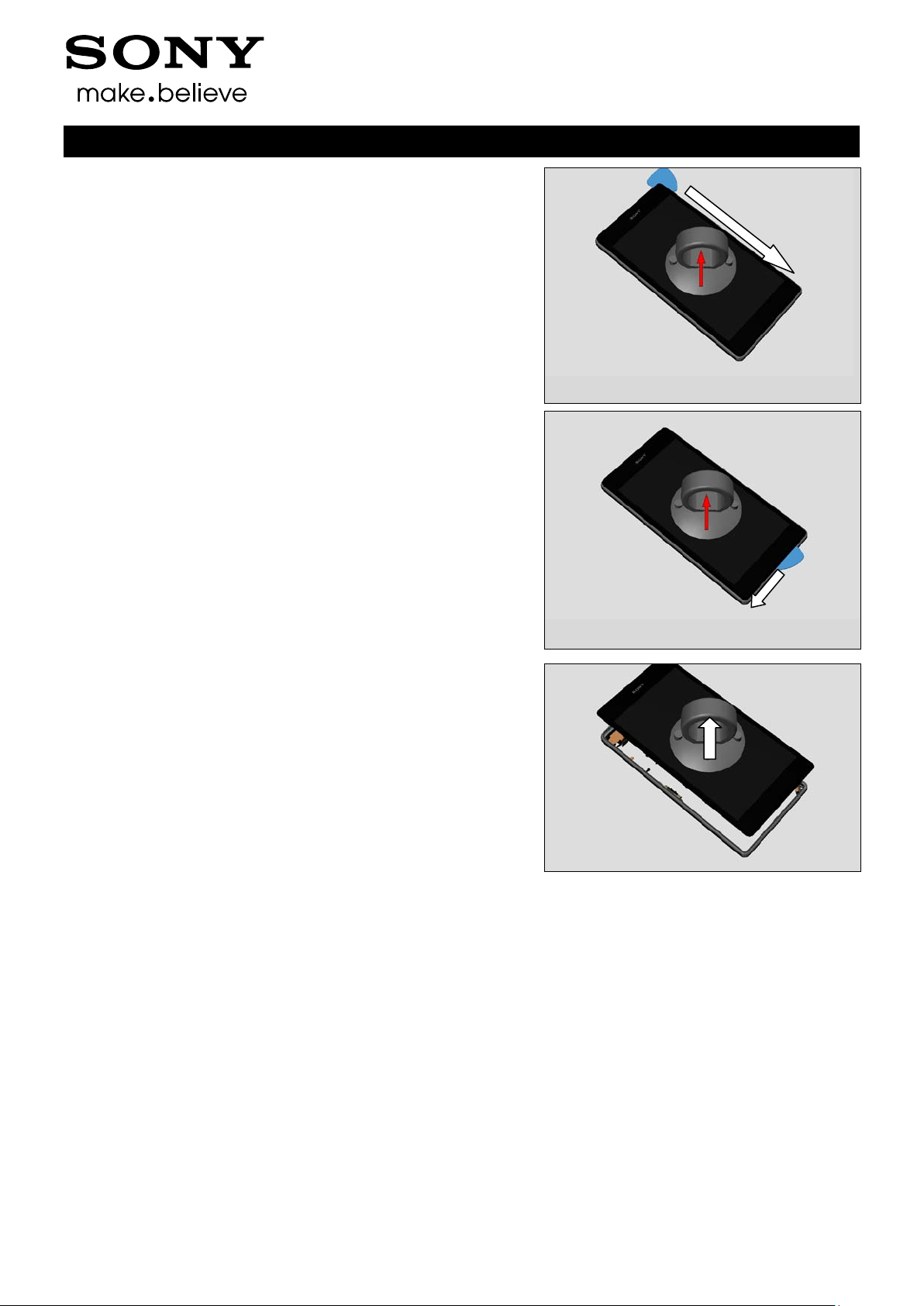
Remove the Window Back by using the Suction cup.
Note! Be careful when removing the Window back due to the
adhesive between battery and Window Back.
Working Instruction (mech)
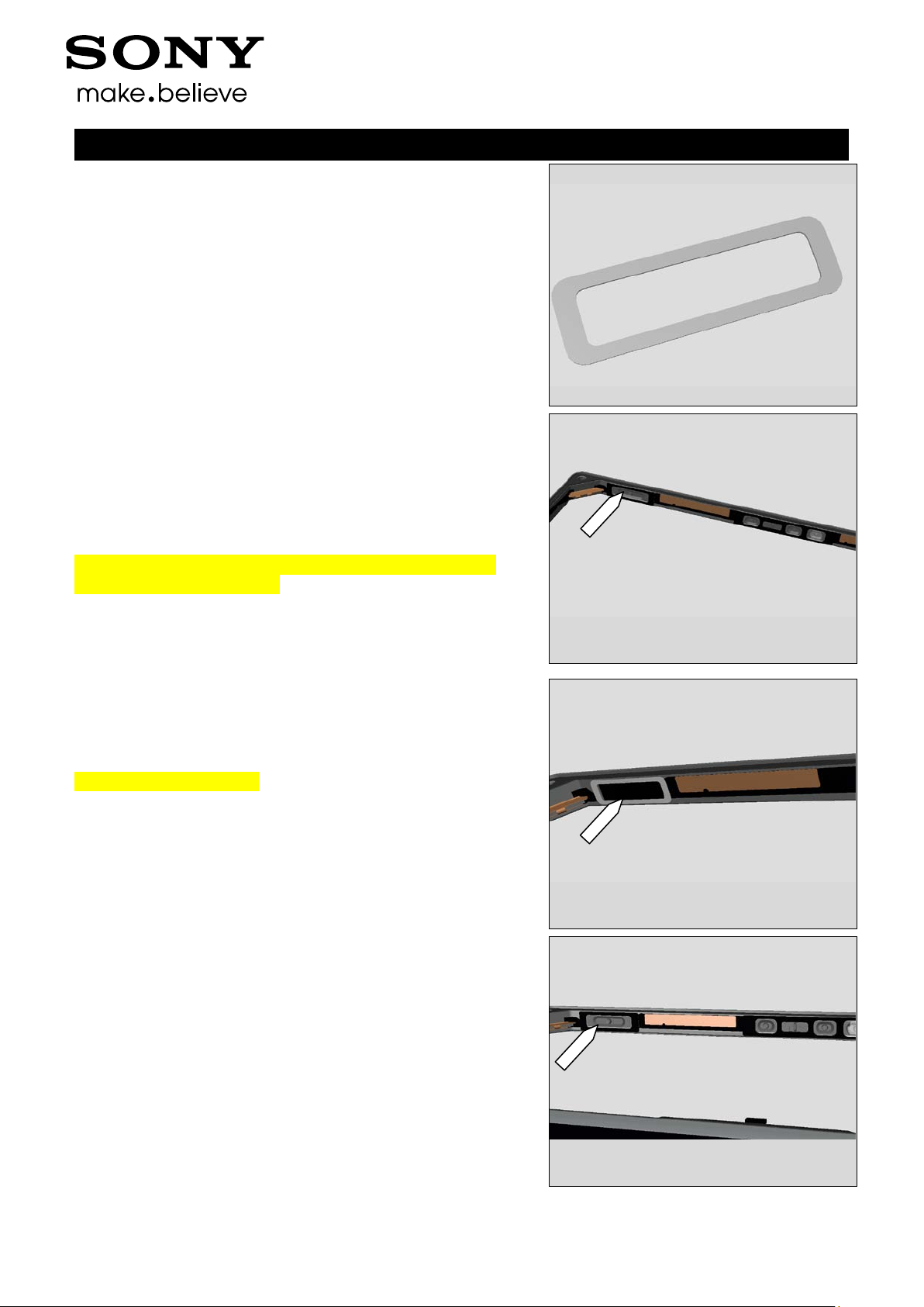
3.2 Rear Cover Assy
Remove the nine Screw 3.5x1.4 by using a screwdriver with
Torx Bits T4.
1277-9813 Rev 2
Sony Mobile Communications AB – Company Internal
11(82)
Disassembly
Use a plectrum to detach right side and the top of the phone
Use a plectrum to detach left side and the bottom of the
phone
Working Instruction (mech)
Use a Front Opening Tool to disconnect the BtB connector.
Remove the Rear Cover Assy with fingers
1277-9813 Rev 2
Sony Mobile Communications AB – Company Internal
12(82)
Disassembly
Use a Front Opening Tool to disconnect the BtB connector.
3.3 Camera
Use a Front Opening Tool to disconnect the BtB connector.
Working Instruction (mech)
Remove the Camera with fingers.
3.4 Shield Camera
Remove the Shield Camera with fingers.
1277-9813 Rev 2
Sony Mobile Communications AB – Company Internal
13(82)
Disassembly
Remove it.
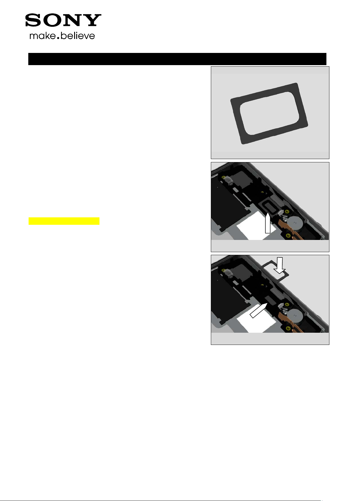
3.5 SIM Tray
Open SIM Cap.
Working Instruction (mech)
Remove the SIM Tray with fingers.
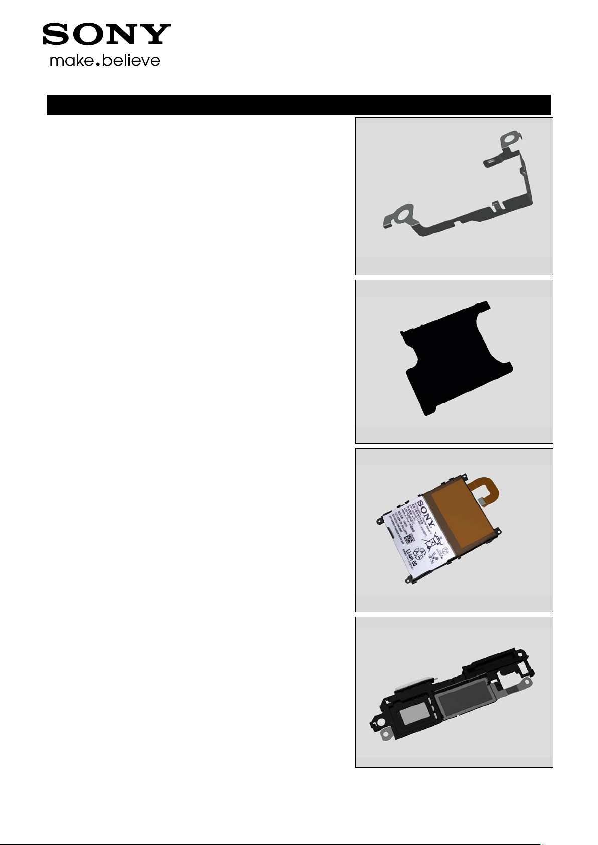
3.6 Battery
Remove the Battery with fingers.
Carefully inspect the Battery after removing it.
Battery with visual signs of been punctured etc. should be
scraped after removal!
1277-9813 Rev 2
Sony Mobile Communications AB – Company Internal
14(82)
Disassembly
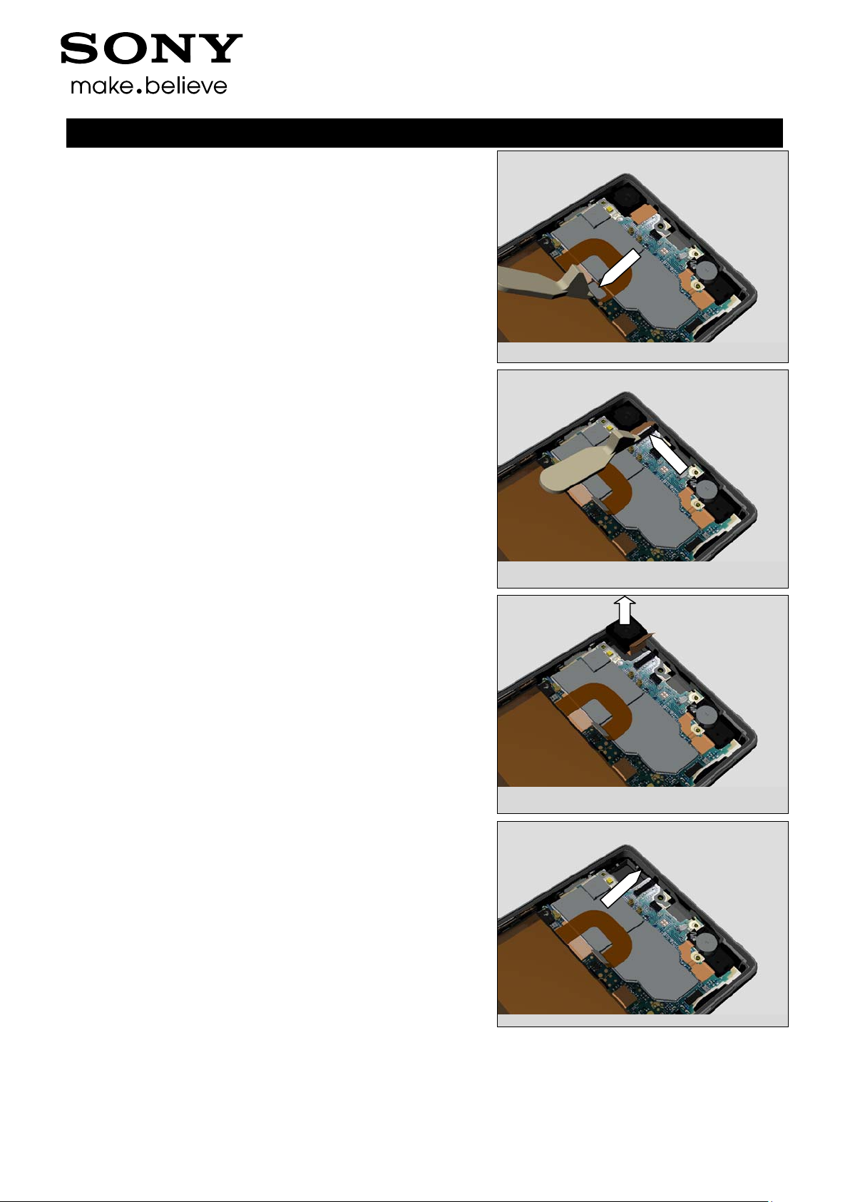
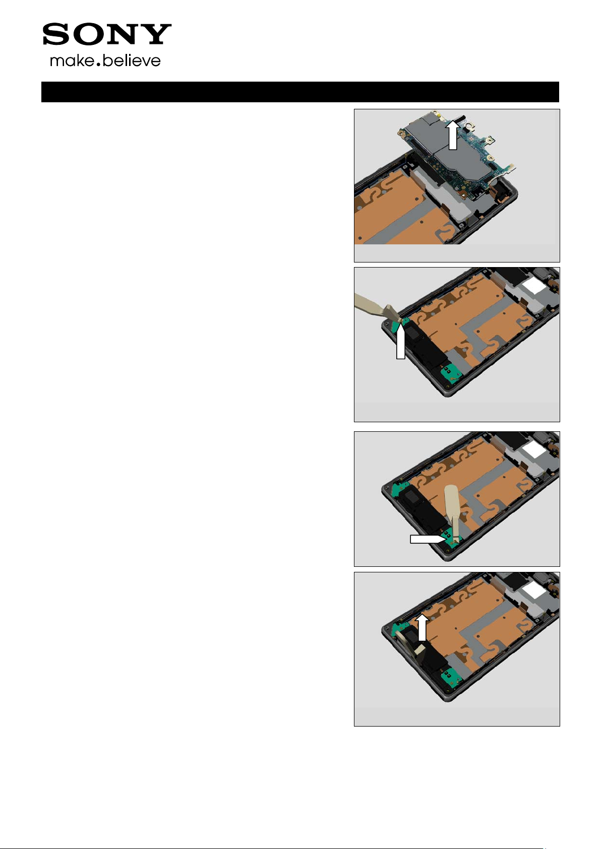
3.7 Main PBA
Use a Front Opening Tool to disconnect the Cable RF B
Working Instruction (mech)
Use a Front Opening Tool to disconnect the Cable RF A
Use a Front Opening Tool to disconnect the FPC Assembly
Charge
Use a Front Opening Tool to disconnect the FPC Assembly
Audio Jack
1277-9813 Rev 2
Sony Mobile Communications AB – Company Internal
15(82)
Disassembly
Use a Front Opening Tool to disconnect the Vibrator
Use a Front Opening Tool to disconnect the FPC Assembly
Relay
Working Instruction (mech)
Use a Front Opening Tool to lift up the Main PBA.
Use a Front Opening Tool to lift up the Main PBA.
1277-9813 Rev 2
Sony Mobile Communications AB – Company Internal
16(82)
Disassembly
Remove the Main PBA with fingers
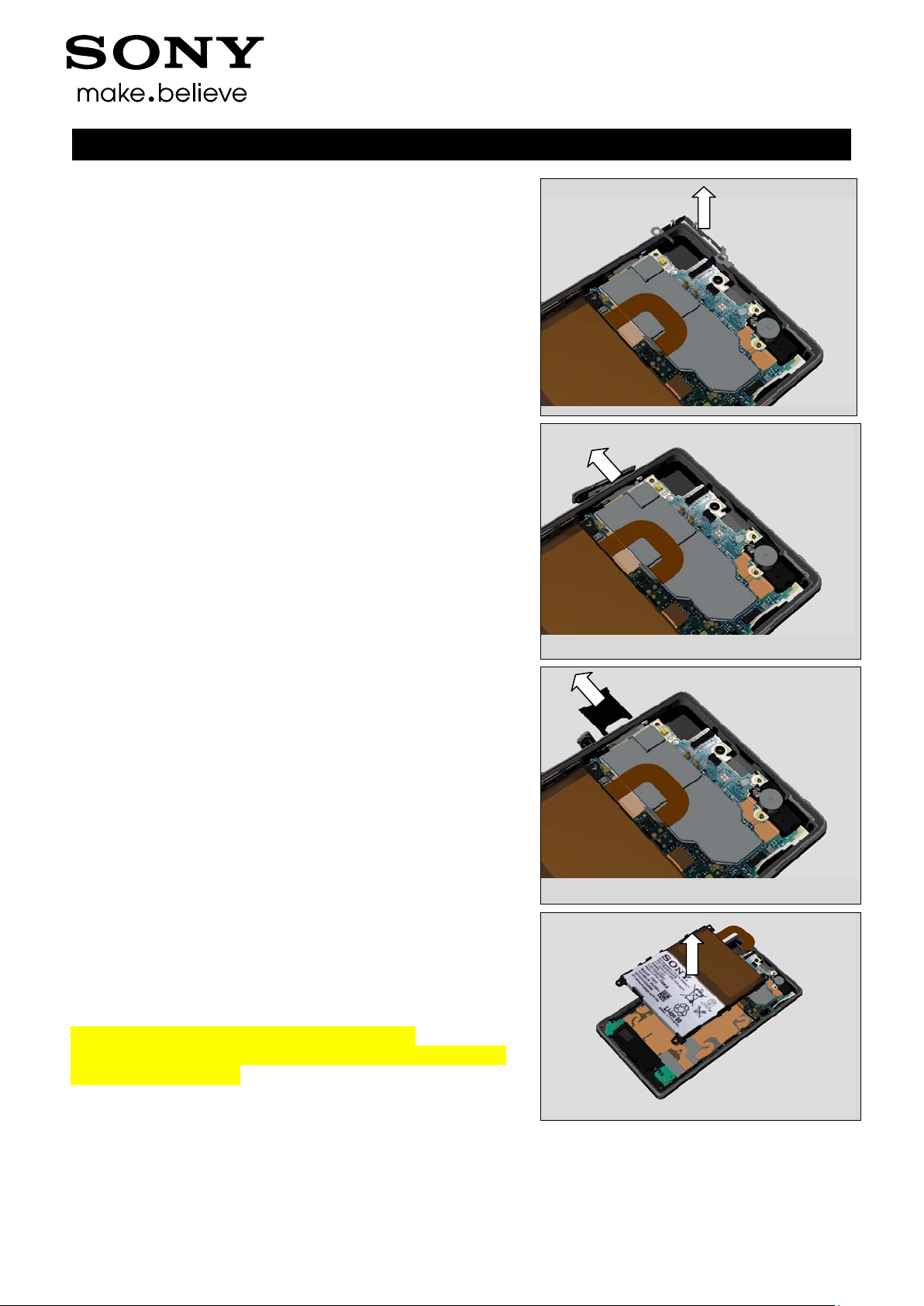
3.8 Loudspeaker Holder
Use a Front Opening Tool to disconnect the Cable RF B
Working Instruction (mech)
Use a Front Opening Tool to disconnect the Cable RF A
Use a Front Opening Tool to lift up the Loudspeaker Holder.
1277-9813 Rev 2
Sony Mobile Communications AB – Company Internal
17(82)
Disassembly
Remove the Loudspeaker Holder with fingers.
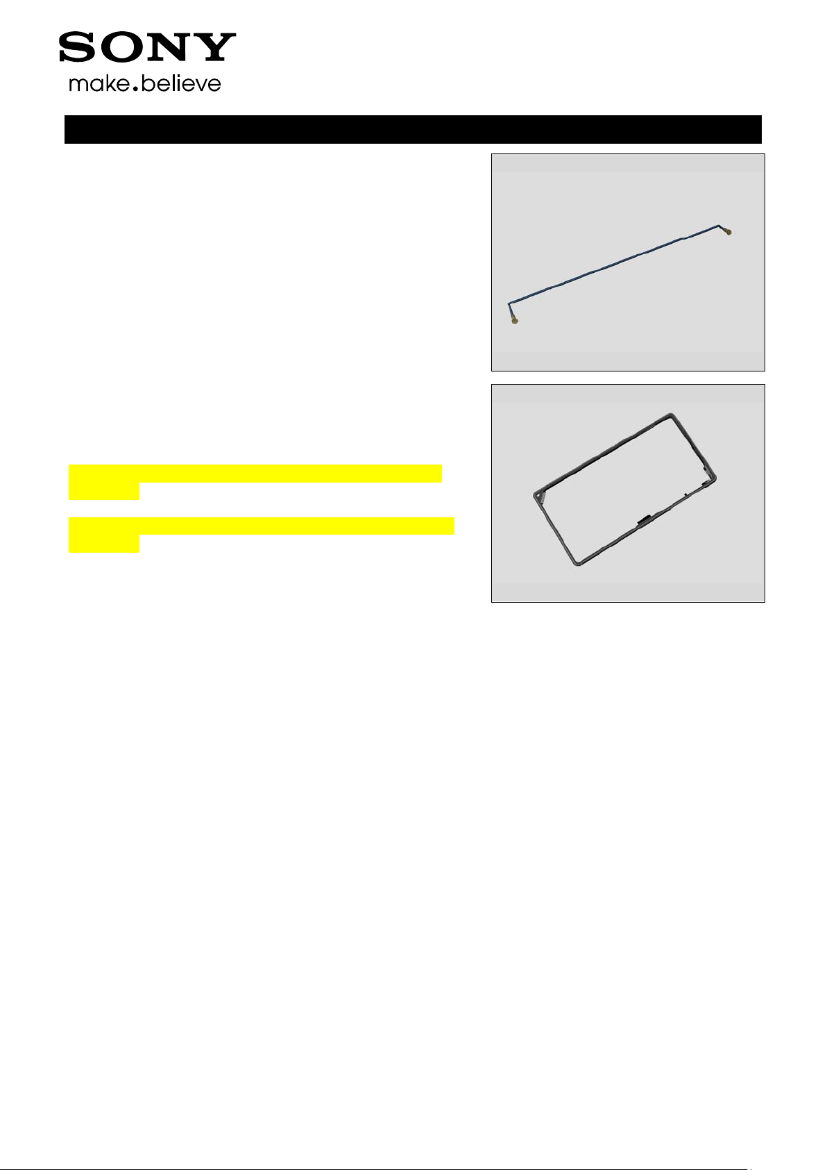
3.9 RF Cable A
Use a pair of tweezers to remove the RF Cable A
Working Instruction (mech)
3.10 Main Frame Assy and Front Cover
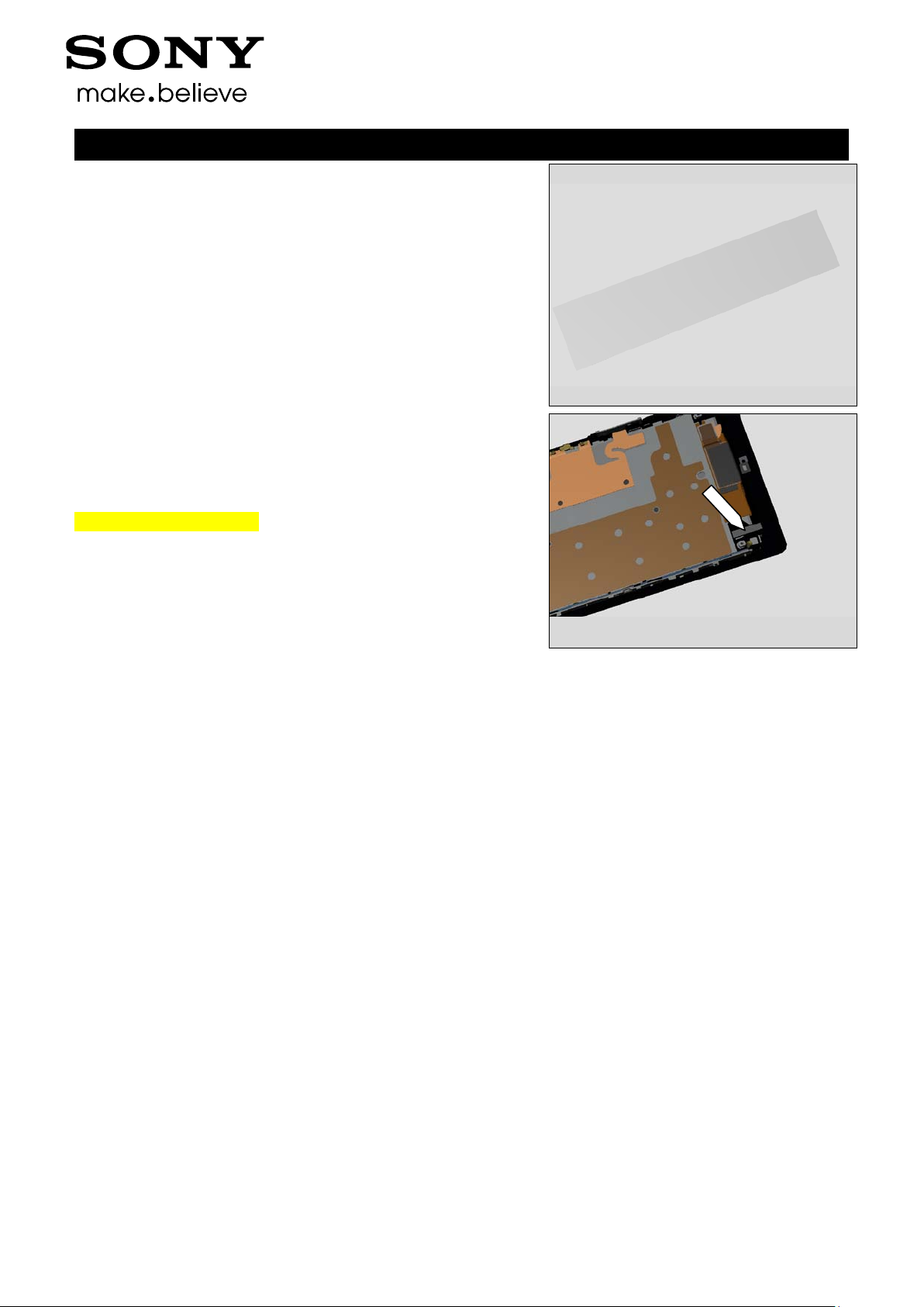
Use Suction cup to get space for inserting the Guitar Pick.
Gently slide the Guitar Pick along to release all sides of the
Main Frame Assy.
1277-9813 Rev 2
Sony Mobile Communications AB – Company Internal
18(82)
Disassembly
Working Instruction (mech)
Remove the Front Cover from Main Frame Assy
1277-9813 Rev 2
Sony Mobile Communications AB – Company Internal
19(82)
4 Replacement
4.1 Window Back
Follow the 3.1 Disassembly instructions!
Note! If reuse of Window Back follow 4.19 Removal
Instruction
Prepare a new Window Back.
Note! If reuse of Window Back follow 4.19 Installation
Instruction
Follow the 5.11 Reassembly instructions!
4.2 Sheet Battery
Follow the 3.1 Disassembly instructions and use a Flex Film
Assembly Tool for removing it from Window Back!
Prepare a new Sheet Battery
Follow the 5.10 and 5.11 Reassembly instructions!
Working Instruction (mech)
4.3 Rear Cover Assy
Follow the 3.1 and 3.2 Disassembly instructions!
Note! If reuse of Rear Cove r Assy follow 4.15 Removal
Instruction
Prepare a new Rear Cover Assy.
Note! If reuse of Rear Cover Assy follow 4.15 Installation
Instruction
Follow the 5.9 - 5.11 Reassembly instructions!
4.4 Camera
Follow the 3.1- 3.3 Disassembly instructions!
Prepare a new Camera.
Follow the 5.8 - 5.11 Reassembly instructions!
1277-9813 Rev 2
Sony Mobile Communications AB – Company Internal
20(82)
Replacement
4.5 Shield Camera
Follow the 3.1 - 3.5 Disassembly instructions!
Prepare a new Shield Camera.
Follow the 5.7 - 5.11 Reassembly instructions!
4.6 SIM Tray
Follow the 3.5 Disassembly instructions!
Prepare a new SIM Tray.
Follow the 5.6 Reassembly instructions!
Working Instruction (mech)
4.7 Battery
Follow the 3.1-3.2 and 3.6 Disassembly instructions!
Prepare a new Battery.
Follow the 5.5 and 5.9-5.11 Reassembly instructions!
4.8 Loudspeaker Holder
Follow the 3.1 – 3.2, 3.6 and 3.8. Disassembly instructions!
Follow the 4.38, 4.40 and 4.41 Removal instructions!
Carry out the Removal as described below!
Prepare a new Loudspeaker Holder
Carry out the Installation as described below!
Follow the 4.38, 4.40 and 4.41 Installation instructions!
Follow the 5.3, 5.5 an d 5.9 - 5.11 Reassembly instructions!
1277-9813 Rev 2
Sony Mobile Communications AB – Company Internal
21(82)
Replacement
4.9 RF Cable A
Follow the 3.1 - 3.2, 3.6 and 3.9 Disassembly instructions!
Prepare a new RF Cable A.
Follow the 5.2, 5. 5 and 5.9-5.11 Reassembly instructions!
4.10 Main Frame Assy
Follow the 3.1-3.10 Disassembly instructions!
Note! If reuse of Main Frame Assy follow 4.17 Removal
Instruction
Prepare a new Main Frame Assy.
Note! If reuse of Main Frame Assy follow 4.17 Installation
Instruction
Follow the 5.1-5.11 Reassembly instructions!
Working Instruction (mech)
1277-9813 Rev 2
Sony Mobile Communications AB – Company Internal
22(82)
Replacement
4.11 Adhesive Earspeaker
Follow the 3.1 – 3.7 Disassembly instructions!
Follow the 4.28 Removal instructions!
Carry out the Removal as described below!
Prepare a new Adhesive Earspeaker!
Carry out the Installation as described below!
Follow the 4.28 Installation instructions!
Follow the 5.4 - 5.11 Reassembly instructions!
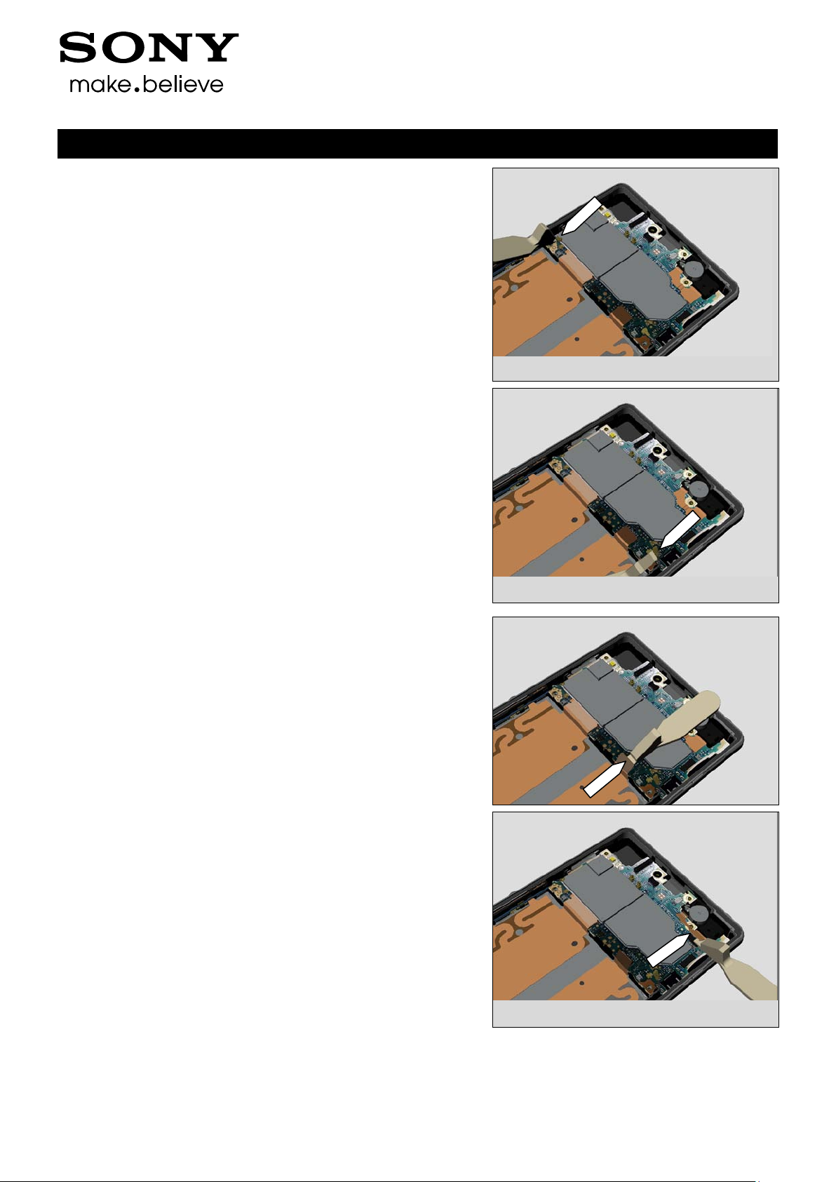
REMOVAL
Detach to remove the Adhesive Earspeaker with the Dentist
Hook.
Scrap! Not to be reused!
Working Instruction (mech)
INSTALLATION
Place a new Adhesive Earspeaker using a Flex Film
Assembly Tool.
1277-9813 Rev 2
Sony Mobile Communications AB – Company Internal
23(82)
Replacement
4.12 Adhesive FPC Relay Bottom
Follow the 3.1 – 3.10 Disassembly instructions!
Follow the 4.32 Removal instructions!
Carry out the Removal as described below!
Prepare a new Adhesive FPC Relay Bottom!
Carry out the Installation as described below!
Follow the 4.32 Installation instructions!
Follow the 5.1 - 5.11 Reassembly instructions!
REMOVAL
Detach to remove the Adhesive FPC Relay Bottom with a pair
of tweezers.
Scrap! Not to be reused!
INSTALLATION
Place a new Adhesive FPC Relay Bottom using a Flex Film
Assembly Tool.
Working Instruction (mech)
1277-9813 Rev 2
Sony Mobile Communications AB – Company Internal
24(82)
Replacement
4.13 Adhesive WP Audio Jack
Follow the 3.1 – 3.10 Disassembly instructions!
Follow the 4.29 Removal instructions!
Carry out the Removal as described below!
Prepare a new Adhesive WP Audio Jack!
Carry out the Installation as described below!
Follow the 4.29 Installation instructions!
Follow the 5.1 - 5.11 Reassembly instructions!
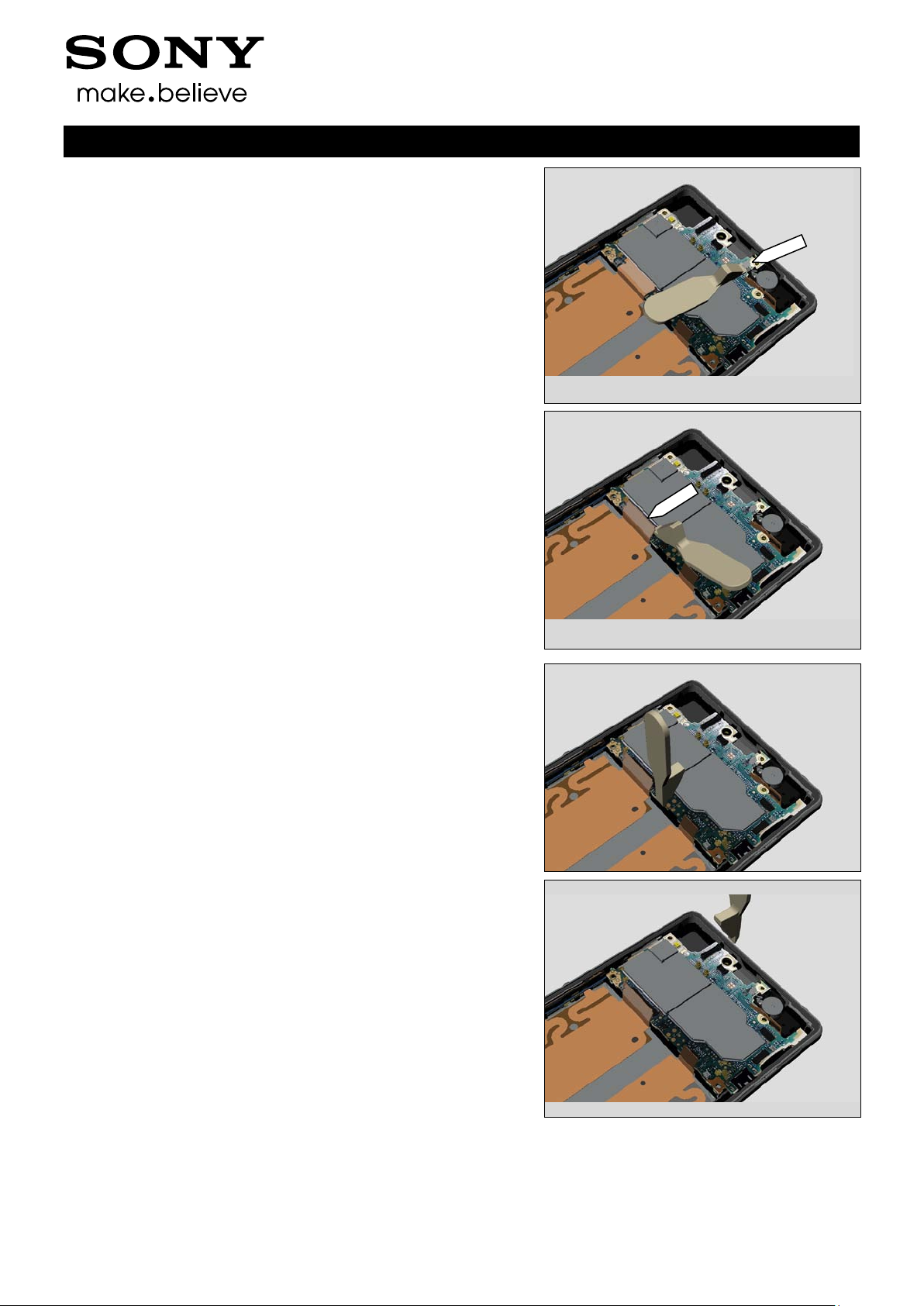
REMOVAL
Remove the Adhesive WP Audio Jack with the Flex Film
Assembly Tool.
Scrap! Not to be reused!
INSTALLATION
Place a new Adhesive WP Audio Jack with Flex Film
Assembly Tool.
Working Instruction (mech)
1277-9813 Rev 2
Sony Mobile Communications AB – Company Internal
25(82)
Replacement
4.14 Adhesive WP Cam era Key
Follow the 3.1 – 3-10 Disassembly instructions!
Carry out the Removal as described below!
Prepare a new Adhesive WP Camer a Key!
Carry out the Installation as described below!
Follow the 5.1 - 5.11 Reassembly instructions!
REMOVAL
Detach to remove the Gasket Camera Key with the Flex Film
Assembly Tool.
Note! Please be careful when disassembly because this
gasket needs to be reused!
Working Instruction (mech)
Detach to remove the Adhesive WP Camera Key with the
Dentist Hook.
Scrap! Not to be reused!
INSTALLATION
Place a new Adhesive WP Camera Key on the Main Frame
Assy using a Flex Film Assembly Tool.
1277-9813 Rev 2

Sony Mobile Communications AB – Company Internal
26(82)
Replacement
4.15 Adhesive WP Cover Rear
Follow the 3.1 and 3.2 Disassembly instructions!
Carry out the Removal as described below!
Prepare a new Adhesive WP Cover Rear!
Carry out the Installation as described below!
Follow the 5.9 - 5.11 Reassembly instructions!
REMOVAL
Remove the Adhesive WP Cover Rear with fingers.
Scrap! Not to be reused!
Working Instruction (mech)
INSTALLATION
Place a new
Adhesive WP Cover Rear w i th fingers in the
Rear Cover Adhesive fixture (Bottom Part).
Then place the old Rear Cover Assy above Adhesive WP
Cover Rear Important to make sure that old adhesive is
removed before installation because of WRT requirement!
Place the Upper part of the fixture and press by hand for 10
sec
1277-9813 Rev 2

Sony Mobile Communications AB – Company Internal
27(82)
Replacement
4.16 Adhesive WP Loudspeaker
Follow the 3.1 – 3.2, 3.6 and 3.8. Disassembly instructions!
Follow the 4.38 Removal instructions!
Carry out the Removal as described below!
Prepare a new Adhesive WP Loudspeaker!
Carry out the Installation as described below!
Follow the 4.38 Installation instructions!
Follow the 5.3, 5.5 and 5.9 - 5.11 Reassembly instructions!
REMOVAL
Detach to remove the Adhesive WP Loudspeaker with a
Dentist Hook.
Scrap! Not to be reused!
Working Instruction (mech)
INSTALLATION
Place a new Adhesive WP Loudspeaker by using a Flex Film
Assembly Tool.
1277-9813 Rev 2

Sony Mobile Communications AB – Company Internal
28(82)
Replacement
4.17 Adhesive WP Main Frame Assy
Follow the 3.1 - 3.10 Disassembly instructions!
Carry out the Removal as described below!
Prepare a new Adhesive WP Main Frame Assy!
Carry out the Installation as described below!
Follow the 5.1 - 5.11 Reassembly instructions!
REMOVAL
Remove the Adhesive WP Main Frame Assy with fingers.
Scrap! Not to be reused!
Working Instruction (mech)
INSTALLATION
Take the Bottom Part of the Main Frame Assy Adhesive
fixture
Place a new Adhesive WP Main Frame Assy with fingers in
the Main Frame Assy Adhesive fixture (Bottom Part)
1277-9813 Rev 2

Sony Mobile Communications AB – Company Internal
29(82)
Replacement
Then place the old Main Frame Assy above the Adhesive
WP Main Frame Assy
Important to make sure that old adhesive is removed before
installation because of WRT requirement!
Place the Upper part of the fixture and press by hand for 10
sec
Working Instruction (mech)
1277-9813 Rev 2

Sony Mobile Communications AB – Company Internal
30(82)
Replacement
4.18 Adhesive WP Side Key
Follow the 3.1 - 3.10 Disassembly instructions!
Follow the 4.35 Removal instructions!
Carry out the Removal as described below!
Prepare a new Adhesive WP Side Key!
Carry out the Installation as described below!
Follow the 4.35 Installation instructions!
Follow the 5.1 - 5.11 Reassembly instructions!
REMOVAL
Detach to remove the Adhesive WP Side Key with the
Dentist Hook.
Scrap! Not to be reused!
INSTALLATION
Place a new Adhesive WP Side Key on the Main Frame
Assy using a Flex Film Assembly Tool.
Working Instruction (mech)
1277-9813 Rev 2

Sony Mobile Communications AB – Company Internal
31(82)
Replacement
4.19 Adhesive WP W i ndow Back
Follow the 3.1 Disassembly instructions!
Carry out the Removal as described below!
Prepare a new Adhesive WP Window Back!
Carry out the Installation as described below!
Follow the 5.10 and 5.11 Reassembly instructions!
REMOVAL
Remove the Adhesive WP Window Back with fingers.
Scrap! Not to be reused!
Working Instruction (mech)
INSTALLATION
Take the Bottom Part of the Window Back Adhesive fixture
Place a new Adhesive WP Window Back with fingers in the
Window Back Adhesive fixture (Bottom Part)
1277-9813 Rev 2

Sony Mobile Communications AB – Company Internal
32(82)
Replacement
Then place the old Window Back above the Adhesive WP
Window Back
Important to make sure that old adhesive is removed before
installation because of WRT requirement!
Place the Upper part of the fixture and press by hand for 10
sec
Working Instruction (mech)
1277-9813 Rev 2

Sony Mobile Communications AB – Company Internal
33(82)
Replacement
4.20 BT + WLAN Flex Antenna
Follow the 3.1 Disassembly instructions!
Carry out the Removal as described below!
Prepare a new B T + WLAN Flex Antenna!
Carry out the Installation as described below!
Follow the 5.10 and 5.11 Reassembly instructions!
REMOVAL
Remove the BT + WLAN Flex Antenna with the Flex Film
Assembly Tool.
Working Instruction (mech)
INSTALLATION
Place a new BT + WLAN Flex Antenna with fingers.
1277-9813 Rev 2

Sony Mobile Communications AB – Company Internal
34(82)
Replacement
4.21 Camera Holder
Follow the 3.1 - 3.3 Disassembly instructions!
Carry out the Removal as described below!
Prepare a new Camera Holder!
Carry out the Installation as described below!
Follow the 5.8 - 5.11 Reassembly instructions!
REMOVAL
Remove the Camera Holder with fingers.
Working Instruction (mech)
INSTALLATION
Attach the Camera Holder with fingers.
1277-9813 Rev 2

Sony Mobile Communications AB – Company Internal
35(82)
Replacement
4.22 Camera Key
Follow the 3.1 – 3.10 Disassembly instructions!
Carry out the Removal as described below!
Prepare a new Camera Key!
Carry out the Installation as described below!
Follow the 5.1 - 5.11 Reassembly instructions!
REMOVAL
Pull to remove the Camera Key with fingers
INSTALLATION
Insert a new Camera Key with fingers
Working Instruction (mech)
1277-9813 Rev 2

Sony Mobile Communications AB – Company Internal
36(82)
Replacement
4.23 Chat Camera
Follow the 3.1 - 3.7 Disassembly instructions!
Carry out the Removal as described below!
Prepare a new Chat Camera!
Carry out the Installation as described below!
Follow the 5.4 - 5.11 Reassembly instructions!
REMOVAL
Open the Zif contact with a Nylon pointer.
Working Instruction (mech)
Use the Flex Film Assembly Tool to loosen the Chat Camera
flex then use the Front Opening Tool to remove the Chat
Camera.
INSTALLATION
Use the Flex Film Assembly Tool and attach the flex to Zif
contact. Then use fingers for position the new Chat Camera
in the cavity.
1277-9813 Rev 2

Sony Mobile Communications AB – Company Internal
37(82)
Replacement
4.24 Chat Camera Holder
Follow the 3.1 - 3.7 Disassembly instructions!
Carry out the Removal as described below!
Prepare a new Chat Camera Holder!
Carry out the Installation as described below!
Follow the 5.4 - 5.11 Reassembly instructions!
REMOVAL
Remove the Chat Camera Holder with fingers.
Working Instruction (mech)
INSTALLATION
Attach a new Chat Camera Holder with fingers.
1277-9813 Rev 2

Sony Mobile Communications AB – Company Internal
38(82)
Replacement
4.25 Core Unit Label
Carry out the Removal as described below!
Prepare a new Core Unit Label!
Carry out the Installation as described below!
REMOVAL
Open SIM Cap with fingers
Working Instruction (mech)
Pull out the Tray Core Unit Label with finger s and
remove the label with a Dentist Hook.
INSTALLATION
Attach a new Core Unit Label with fingers on the Tray Core
Unit Label. Close the SIM Cap.
1277-9813 Rev 2

Sony Mobile Communications AB – Company Internal
39(82)
REMOVAL
Tool.
Replacement
4.26 Cushion 1st Mic
Follow the 3.1 – 3-10 Disassembly instructions!
Carry out the Removal as described below!
Prepare a new Cushion 1
Carry out the Installation as described below!
Follow the 5.1 - 5.11 Reassembly instructions!
Remove the Cushion 1
Scrap! Not to be reused!
INSTALLATION
Attach a new Cushion 1st Mic with the Flex Film Assembly
st
Mic!
st
Mic with Dentist Hook.
Working Instruction (mech)
1277-9813 Rev 2

Sony Mobile Communications AB – Company Internal
40(82)
Replacement
REMOVAL
Assembly Tool.
4.27 Cushion 2nd Mic
Follow the 3.1 - 3.2 Disassembly instructions!
Follow the 4.31 Removal instructions!
Carry out the Removal as described below!
Prepare a new Cushion 2
Carry out the Installation as described below!
Follow the 4.31 Installation instructions!
Follow the 5.9 - 5.11 Reassembly instructions!
Remove the Cushion 2
Scrap! Not to be reused!
INSTALLATION
Attach a new Cushion 2st Mic with the Flex Film
nd
Mic!
st
Mic with Dentist Hook.
Working Instruction (mech)
1277-9813 Rev 2

Sony Mobile Communications AB – Company Internal
41(82)
Replacement
4.28 Ear Speaker
Follow the 3.1 – 3.7 Disassembly instructions!
Follow the 4.11 Removal instructions!
Carry out the Removal as described below!
Prepare a new Ear Speaker!
Carry out the Installation as described below!
Follow the 4.11 Installation instructions!
Follow the 5.4 - 5.11 Reassembly instructions!
REMOVAL
Remove the Ear Speaker using Front Opening Tool.
Scrap! Not to be reused!
Working Instruction (mech)
INSTALLATION
Place a new Ear Speaker with fingers
Use Press Tool Earspeaker and press for 10s.
1277-9813 Rev 2

Sony Mobile Communications AB – Company Internal
42(82)
Replacement
4.29 FPC Assembly Audi o Jack
Follow the 3.1 – 3.10 Disassembly instructions!
Carry out the Removal as described below!
Prepare a new FPC Assembly Audio Jack!
Carry out the Installation as described below!
Follow the 5.1 - 5.11 Reassembly instructions!
REMOVAL
Detach to remove the FPC Assembly Audio Jack with
fingers.
Working Instruction (mech)
INSTALLATION
Place a new FPC Assembly Audio Jack with fingers.
Use Audio Jack Press and press for 10s.
1277-9813 Rev 2

Sony Mobile Communications AB – Company Internal
43(82)
Replacement
4.30 FPC Assembly Charger
Follow the 3.1 – 3.10 Disassembly instructions!
Follow the 4.46 Removal instructions!
Carry out the Removal as described below!
Prepare a new FPC Assembly Charger!
Carry out the Installation as described below!
Follow the 4.46 Installation instructions!
Follow the 5.1 - 5.11 Reassembly instructions!
REMOVAL
Remove the FPC Assembly Charger with the Flex Film
Assembly Tool.
Not! Be very careful because flex could be reused if no
damage!
Working Instruction (mech)
INSTALLATION
Start by placing the buttons of the new FPC Assembly
Charger with a Flex Film Assembly Tool before assembly the
flex.
1277-9813 Rev 2

Sony Mobile Communications AB – Company Internal
44(82)
Replacement
4.31 FPC Assembly Mic
Follow the 3.1 – 3.2 Disassembly instructions!
Carry out the Removal as described below!
Prepare a new FPC Assembly Mic!
Carry out the Installation as described below!
Follow the 5.9 - 5.11 Reassembly instructions!
REMOVAL
Detach to remove the FPC Assembly Mic with the Flex Film
Assembly Tool and fingers.
Scrap! Not to be reused!
Working Instruction (mech)
INSTALLATION
Place a new FPC Assembly Mic using a Flex Film Assembly
Tool.
Note! Press for 10s to activate the adhesive around
microphone
1277-9813 Rev 2

Sony Mobile Communications AB – Company Internal
45(82)
Replacement
REMOVAL
4.32 FPC Assembly Relay
Follow the 3.1-3.10 Disassembly instructions!
Follow the 4.47 Removal instructions!
Carry out the Removal as described below!
Prepare a new FPC Assembly Relay!
Follow the 4.47 Installation instructions!
Carry out the Installation as described below!
Follow the 5.1 - 5.11 Reassembly instructions!
Start by disconnect the BtB connector against Display flex.
Then remove the FPC Assembly Relay with the Flex Film
Assembly Tool.
Not! Be very careful because flex could be reused if no
damage!
Working Instruction (mech)
INSTALLATION
Start by placing the buttons of the new FPC Assembly Relay
with a Flex Film Assembly Tool before assembly the flex.
Connect BtB connector against Display flex.
1277-9813 Rev 2

Sony Mobile Communications AB – Company Internal
46(82)
Replacement
4.33 Front Cover
Follow the 3.1 - 3.10 Disassembly instructions!
Follow the 4.22, 4.28, 4.30, 4.32 and 4.54 Removal
instructions!
Carry out the Removal as described below!
Prepare a new Front Assembly!
Carry out the Installation as described below!
Follow the 4.22, 4.28, 4.30, 4.32 and 4.54 Installation
instructions!
Follow the 5.1 - 5.11 Reassembly instructions!
Working Instruction (mech)
1277-9813 Rev 2

Sony Mobile Communications AB – Company Internal
47(82)
Replacement
4.34 Gasket Charger
Follow the 3.1- 3.10 Disassembly instructions!
Carry out the Removal as described below!
Prepare a new Gasket Charger!
Carry out the Installation as described below!
Follow the 5.1 - 5.11 Reassembly instructions!
REMOVAL
Detach to remove the Gasket Charger with a Dentist Hook.
Scrap! Not to be reused!
INSTALLATION
Place a new Gasket Charger using a Flex Film Assembly
Tool.
Working Instruction (mech)
1277-9813 Rev 2

Sony Mobile Communications AB – Company Internal
48(82)
Replacement
REMOVAL
Tool.
4.35 Gasket Side Key
Follow the 3.1- 3.10 Disassembly instructions!
Follow the 4.18 Removal instructions!
Carry out the Removal as described below!
Prepare a new Gasket Side Key!
Carry out the Installation as described below!
Follow the 4.18 Installation instructions!
Follow the 5.1 - 5.11 Reassembly instructions!
Remove the Gasket Side Key with the Flex Film Assembly
Tool.
INSTALLATION
Place a new Gasket Side Key using a Flex Film Assembly
Working Instruction (mech)
1277-9813 Rev 2

Sony Mobile Communications AB – Company Internal
49(82)
Replacement
4.36 Holder Magnetic Charger Connector
Follow the 3.1 - 3.6 and 3.9 Disassembly instructions!
Carry out the Removal as described below!
Prepare a new Holder Magnetic Charger Connector!
Carry out the Installation as described below!
Follow the 5.2, 5.5 and 5.9-5.11 Reassembly
instructions!
REMOVAL
Detach to remove Holder Magnetic Charger Connector with a
pair of tweezers.
INSTALLATION
Place a new Holder Magnetic Charger Connector using a
pair of tweezers.
Working Instruction (mech)
1277-9813 Rev 2

Sony Mobile Communications AB – Company Internal
50(82)
Replacement
4.37 Liquid indicator
Carry out the Removal as described below!
Prepare a new Liquid indicator!
Carry out the Installation as described below!
REMOVAL
Detach to remove the Liquid indicator with a Dentist Hook
Scrap! Not to be reused!
INSTALLATION
Place a new Liquid indicator follow the guiding lines on the
Rear Cover Assy using a Front Assembly Tool.
Working Instruction (mech)
1277-9813 Rev 2

Sony Mobile Communications AB – Company Internal
51(82)
Replacement
4.38 Loudspeaker
Follow the 3.1 – 3.2, 3.6 and 3.8 Disassembly instructions!
Follow the 4.16 Removal instructions!
Carry out the Removal as described below!
Prepare a new Loudspeaker!
Carry out the Installation as described below!
Follow the 4.16 Installation instructions!
Follow the 5.3, 5.5 and 5.9 - 5.11 Reassembly instructions!
REMOVAL
Detach to remove the Loudspeaker with the Front Opening
Tool.
Scrap! Not to be reused!
Working Instruction (mech)
INSTALLATION
Place a new Loudspeaker by using fingers
Press to secure its attachment by using Press Tool
Loudspeaker for five seconds.
Do not touch the contact pins!
1277-9813 Rev 2

Sony Mobile Communications AB – Company Internal
52(82)
Replacement
4.39 Magnetic charger connector
Follow the 3.1 - 3.6 and 3.9 Disassembly instructions!
Follow the 4.36 Removal instructions!
Carry out the Removal as described below!
Prepare a new Magnetic charger connector!
Carry out the Installation as described below!
Follow the 4.36 Installation instructions!
Follow the 5.2, 5.5 and 5.9-5.11 Reassembly
instructions!
REMOVAL
Push the two pads of Magnetic charger connector by using
Flex Film Assembly Tool.
Scrap! Not to be reused!
Be careful! Do not damage the two pins of FPC charger.
Working Instruction (mech)
INSTALLATION
Mount a new Magnetic charger connector by fingers.
Check and press the two pins into its cavities by using the
Front Opening Tool.
Be careful! Do not damage the two pins of FPC charger.
Then use Side Panel press, Side Panel Press Head and
Charge connector press pad with the force of 60N for five
seconds. According to 1003-9107 Tool Catalogue –
mechanical and document Side Panel press Instruction for
use.
1277-9813 Rev 2

Sony Mobile Communications AB – Company Internal
53(82)
Replacement
4.40 PBA Cellular Sub
Follow the 3.1 – 3.2, 3.6 and 3.8 Disassembly instructions!
Carry out the Removal as described below!
Prepare a new PBA Cellular Sub!
Carry out the Installation as described below!
Follow the 5.3, 5.5 an d 5.9 - 5.11 Reassembly instructions!
REMOVAL
Remove the PBA Cellular Sub with the Front Opening Tool.
Working Instruction (mech)
INSTALLATION
Place a new PBA Cellular Sub using fingers in the cavity of
Loudspeaker Holder.
1277-9813 Rev 2

Sony Mobile Communications AB – Company Internal
54(82)
Replacement
4.41 PBA WL AN S ub
Follow the 3.1 – 3.2, 3.6 and 3.8 Disassembly instructions!
Carry out the Removal as described below!
Prepare a new PBA WLAN Sub!
Carry out the Installation as described below!
Follow the 5.3, 5.5 an d 5.9 - 5.11 Reassembly instructions!
REMOVAL
Remove the PBA WLAN Sub with the Front Opening Tool.
Working Instruction (mech)
INSTALLATION
Place a new PBA WLAN Sub using fingers in the cavity of
Loudspeaker Holder.
1277-9813 Rev 2

Sony Mobile Communications AB – Company Internal
55(82)
Replacement
REMOVAL
4.42 Plate Contact RF A
Follow the 3.1 - 3.6 and 3.9 Disassembly instructions!
Carry out the Removal as described below!
Prepare a new Holder Magnetic Charger Connector!
Carry out the Installation as described below!
Follow the 5.2, 5.5 and 5.9-5.11 Reassembly
instructions!
Detach to remove the Holder Magnetic Charger Connector
with a pair of tweezers.
INSTALLATION
Place a new Holder Charger Connector using a pair of
tweezers
Working Instruction (mech)
1277-9813 Rev 2

Sony Mobile Communications AB – Company Internal
56(82)
Replacement
4.43 Power Key
Follow the 3.1 – 3.10 Disassembly instructions!
Follow the 4.35, 4.18 Removal instructions!
Carry out the Removal as described below!
Prepare a new Power Key!
Carry out the Installation as described below!
Follow the 4.18, 4.35 Installation instructions!
Follow the 5.1 - 5.11 Reassembly instructions!
REMOVAL
Pull to remove the Power Key with fingers
INSTALLATION
Insert a new Power Key with fingers
Working Instruction (mech)
1277-9813 Rev 2

Sony Mobile Communications AB – Company Internal
57(82)
Re-Assembly
4.44 RF Cable B
Follow the 3.1 - 3.2, 3.6 and 3.9 Disassembly instructions!
Carry out the Removal as described below!
Prepare a new RF Cable B!
Carry out the Installation as described below!
Follow 5.5 and 5.9-5.11 Reassembly instructions!
REMOVAL
Release the RF Cable B with the Flex Film Assembly Tool.
Note! Careful not to break the two connectors!
Working Instruction (mech)
INSTALLATION
Place a new RF Cable B using a Flex Film Assembly Tool.
Connect the two connectors with fingers
Note! Important that the silver parts of the RF Cable B is
placed in the two sockets.
1277-9813 Rev 2

Sony Mobile Communications AB – Company Internal
58(82)
Replacement
4.45 SD Cap
Carry out the Removal as described below!
Prepare a new SD Cap!
Carry out the Installation as described below!
REMOVAL
Detach to remove the SD Cap with fingers
INSTALLATION
Place a new SD Cap with fingers and a pair of tweezers
Working Instruction (mech)
1277-9813 Rev 2

Sony Mobile Communications AB – Company Internal
59(82)
Replacement
REMOVAL
Film Assembly Tool.
4.46 Sheet Conductive Charger FPC
Follow the 3.1-3.10 Disassembly instructions!
Follow the 4.30 Removal instructions!
Carry out the Removal as described below!
Prepare a new Sheet Conductive Charger FPC!
Follow the 4.30 Installation instructions!
Carry out the Installation as described below!
Follow the 5.1 - 5.11 Reassembly instructions!
Detach to remove the Sheet Conductive Charger FPC with
Nylon Pointer.
Scrap! Not to be reused!
INSTALLATION
Place a new Sheet Conductive Charger FPC using a Flex
Working Instruction (mech)
1277-9813 Rev 2

Sony Mobile Communications AB – Company Internal
60(82)
Replacement
REMOVAL
4.47 Sheet Conductiv e Relay FPC
Follow the 3.1-3.10 Disassembly instructions!
Follow the 4.32 Removal instructions!
Carry out the Removal as described below!
Prepare a new Sheet Conductive Relay FPC!
Follow the 4.32 Installation instructions!
Carry out the Installation as described below!
Follow the 5.1 - 5.11 Reassembly instructions!
Detach to remove the Sheet Conductive Charger FPC with
Nylon Pointer.
Scrap! Not to be reused!
INSTALLATION
Place a new Sheet Conductive Charger FPC using a Flex
Film Assembly Tool.
Working Instruction (mech)
1277-9813 Rev 2

Sony Mobile Communications AB – Company Internal
61(82)
Replacement
4.48 Sheet Thermal A
Follow the 3.1-3.7 Disassembly instructions!
Carry out the Removal as described below!
Prepare a new Sheet Thermal A!
Carry out the Installation as described below!
Follow the 5.4 - 5.11 Reassembly instructions!
REMOVAL
Detach to remove the Sheet Thermal A with Dentis t Hook.
Scrap! Not to be reused!
INSTALLATION
Place a new Sheet Thermal A using a Flex Film Assembly
Tool
Working Instruction (mech)
1277-9813 Rev 2

Sony Mobile Communications AB – Company Internal
62(82)
Replacement
REMOVAL
4.49 Sheet Thermal B
Follow the 3.1-3.7 Disassembly instructions!
Carry out the Removal as described below!
Prepare a new Sheet Thermal B!
Carry out the Installation as described below!
Follow the 5.4 - 5.11 Reassembly instructions!
Detach to remove the Sheet Thermal B with Dentist Hook.
Scrap! Not to be reused!
INSTALLATION
Place a new Sheet Thermal B using a Flex Film Assembly
Tool
Working Instruction (mech)
1277-9813 Rev 2

Sony Mobile Communications AB – Company Internal
63(82)
Replacement
4.50 Sheet WP 2nd Mic
Follow the 3.1 Disassembly instructions!
Carry out the Removal as described below!
Prepare a new Sheet WP 2
Carry out the Installation as described below!
Follow the 5.10 - 5.11 Reassembly instructions!
REMOVAL
Detach to remove the Sheet WP 2
Scrap! Not to be reused!
nd
Mic!
nd
Mic with Dentist Hook.
Working Instruction (mech)
INSTALLATION
Place a new Sheet WP 2
Tool
nd
Mic using a Flex Film Assembly
1277-9813 Rev 2

Sony Mobile Communications AB – Company Internal
64(82)
Replacement
4.51 Sheet WP Check
Follow the 3.1-3.10 Disassembly instructions!
Carry out the Removal as described below!
Prepare a new Sheet WP Check!
Carry out the Installation as described below!
Follow the 5.1 - 5.11 Reassembly instructions!
REMOVAL
Detach to remove the Sheet WP Check with Dentis t Hook.
Scrap! Not to be reused!
Working Instruction (mech)
INSTALLATION
Place a new Sheet WP Check using a Flex Film Assembly
Tool
1277-9813 Rev 2

Sony Mobile Communications AB – Company Internal
65(82)
Replacement
4.52 SIM Cap
Carry out the Removal as described below!
Prepare a new SIM Cap!
Carry out the Installation as described below!
REMOVAL
Detach to remove the SIM Cap with fingers
INSTALLATION
Place a new SIM Cap with fingers and a pair of
tweezers
Working Instruction (mech)
1277-9813 Rev 2

Sony Mobile Communications AB – Company Internal
66(82)
Replacement
4.53 Speaker Pan el
Carry out the Removal as described below!
Prepare a new Speaker Panel!
Carry out the Installation as described below!
REMOVAL
Detach to remove the Speaker Panel with the Dentist Hook...
Scrap! Not to be reused!
INSTALLATION
Place a new Speaker P anel w i th fing er s and pr es s for
10 sec over the panel.
Working Instruction (mech)
1277-9813 Rev 2

Sony Mobile Communications AB – Company Internal
67(82)
Replacement
4.54 Tray Core Unit Label
Follow the 3.1-3.7 Disassembly instructions!
Follow the 4.25 Removal instructions!
Carry out the Removal as described below!
Prepare a new Tray Core Unit Label!
Carry out the Installation as described below!
Follow the 4.25 Installation instructions!
Follow the 5.4 - 5.11 Reassembly instructions!
REMOVAL
Open the SIM Cap with fingers. Pull out the Tray Core Unit
Label with fingers and lift up the Tray Core Unit Label around
the arrows before releasing it.
Working Instruction (mech)
INSTALLATION
Place a new Tray Core Unit Label and put it in the cavity.
Close the SIM Cap.
1277-9813 Rev 2

Sony Mobile Communications AB – Company Internal
68(82)
Replacement
4.55 USB Cap
Carry out the Removal as described below!
Prepare a new USB Cap!
Carry out the Installation as described below!
REMOVAL
Detach to remove the USB Cap with fingers
INSTALLATION
Place a new USB Cap with fingers and a pair of
tweezers
Working Instruction (mech)
1277-9813 Rev 2

Sony Mobile Communications AB – Company Internal
69(82)
Replacement
4.56 USB Holder
Follow the 3.1-3.7 Disassembly instructions!
Carry out the Removal as described below!
Prepare a new USB Holder!
Carry out the Installation as described below!
Follow the 5.4 - 5.11 Reassembly instructions!
REMOVAL
Detach to remove the USB Holder with fingers
INSTALLATION
Place a new USB Holder with fingers.
Working Instruction (mech)
1277-9813 Rev 2

Sony Mobile Communications AB – Company Internal
70(82)
Replacement
4.57 Vibrator
Follow the 3.1 - 3.2 Disassembly instructions!
Carry out the Removal as described below!
Prepare a new Vibrator!
Carry out the Installation as described below!
Follow the 5.9 - 5.11 Reassembly instructions!
REMOVAL
Disconnect the con nector of Vibr ator by using a Front
Opening Tool.
Working Instruction (mech)
Detach to remove the Vibrator with Front Opening Tool
INSTALLATION
Place a new Vibrator into the cavity using fingers and connect
to Main PBA
1277-9813 Rev 2

Sony Mobile Communications AB – Company Internal
71(82)
Replacement
4.58 Volume Key
Follow the 3.1-3.10 Disassembly instructions!
Follow the 4.35 and 4.18 Removal instructions!
Carry out the Removal as described below!
Prepare a new Volume Key!
Carry out the Installation as described below!
Follow the 4.18 and 4.35 Installation instructions!
Follow the 5.1 - 5.11 Reassembly instructions!
REMOVAL
Pull to remove the Volume Key with fingers
INSTALLATION
Insert a new Volume Key with fingers
Working Instruction (mech)
1277-9813 Rev 2

Sony Mobile Communications AB – Company Internal
72(82)
Replacement
4.59 Board Swap - Replacement
Follow the 3.1 to 3.7 Disassembly instructions!
Follow the 4.23 and 4.56 Removal instructions!
Reuse the Camera, Chat Camera and Battery!
Replace the Swap Board.
Follow the 4.23 and 4.56 Installation instructions!
Follow the 5.4 to 5.11 Reassembly instructions!
Press the Key On/Off to power on the phone, place unit on
flat desk and wait 4 minutes until system boot up has been
completed.
Please DO NOT move the phone during starting up until
“Select Language” menu is shown on the display!
After “Select Language” menu, turn off the phone.
Follow the Calibration chapter 3.1 and 3.2 in 1277-9815
Test Instruction – mechanical
Working Instruction (mech)
1277-9813 Rev 2

Sony Mobile Communications AB – Company Internal
73(82)
C6902, C6903, C6906, L39h
5 Re-Assembly
The Re-ass embly is done to the following modules:
1. Front Cover (a) and Main Frame Assy (b)
2. RF Cable A
3. Loudspeaker Holder
4. Main PBA
5. Battery
6. SIM Tray
7. Shield Camera
8. Camera
9. Rear Cover Assy
10. Sheet Battery
11. Window Back
Working Instruction (mech)
5.1 Front Cover and Main Frame Assy
Follow the 4.17 removal and installation instruction to
replace a new Adhesive WP Main Frame Assy
Place the Front Cover on the Main Frame Assy
Press with fingers to secure the contact of adhesive
between Front Cover and Main Frame Assy
1277-9813 Rev 2

Sony Mobile Communications AB – Company Internal
74(82)
Re-Assembly
5.2 RF Cable A
Place the RF Cable A to the Main Frame Assy
Place a new Cable RF Cable A using a Flex Film Assembly
Tool.
Working Instruction (mech)
Note! Important that the silver parts of the RF Cable A is
placed in the three sockets.
5.3 Loudspeaker Holder
Place the Loudspeaker Holder to Main Frame Assy
1277-9813 Rev 2

Sony Mobile Communications AB – Company Internal
75(82)
Re-Assembly
Use fingers to secure the position of Loudspeaker Holder
Working Instruction (mech)
Use fingers to secure positions of RF Cable A and RF Cable
B
5.4 Main PBA
Place the Main PBA gently into the cavity
Use fingers to secure position of Main PBA
1277-9813 Rev 2

Sony Mobile Communications AB – Company Internal
76(82)
Re-Assembly
Press with fingers to secure the position of BtB conectors,
RF Cable A and RF Cable B
5.5 Battery
Place the Battery gently into the cavity
Working Instruction (mech)
Use fingers to secure the position of the Battery
5.6 SIM Tray
Open SIM Cap.
1277-9813 Rev 2

Sony Mobile Communications AB – Company Internal
77(82)
Re-Assembly
Use with fingers to secure the SIM Tray then close SIM Cap
5.7 Shield Camera
Use a pair of tweezers to position Shield Camera into the
cavity
Working Instruction (mech)
Secure the position with a pair of tweezers
5.8 Camera
Use fingers to position Camera into the cavity
1277-9813 Rev 2

Sony Mobile Communications AB – Company Internal
78(82)
Re-Assembly
Press with fingers to secure the contact of Camera
5.9 Rear Cover Assy
Press with fingers to secure the contact of Battery
Working Instruction (mech)
Follow the 4.15 removal and installation instruction to
replace a new Adhesive WP Cover Rear
Use Isopropyl Alcohol - 99 % for clean around the edges of
Main Frame Assy before assembly Rear Cover Assy
Place the Rear Cover Assy on the frame
Press with fingers to secure the contact of Chat Camera
1277-9813 Rev 2

Sony Mobile Communications AB – Company Internal
79(82)
Re-Assembly
Upper inlay = Rear Cover Press Inlay
Lower inlay = Bottom Press Inlay
Place the phone in the Bottom Press Inlay and follow the
instruction in 1003-9107 Tool Catalogue – mechanical and
document Toothed Rack Press Instruction for use.
Press it with a pressure value of 483N +/- 50 N / 10 sec
(pressure value is adjust from 600N because of the weight of
the press fixture)
Working Instruction (mech)
Apply 13 Ncm torque when tightening the Screw 3.5x1.4 with
Torx Bits T4
1277-9813 Rev 2

Sony Mobile Communications AB – Company Internal
80(82)
Re-Assembly
5.10 Sheet Battery
Use a Flex Film Assembly Tool and fingers for assembly the
Sheet Battery on the Battery
5.11 Window Back
Follow the 4.18 removal and installation instruction to replace
a new Adhesive WP Window Back
Use Isopropyl Alcohol - 99 % for clean around the edges of
Rear Cover Assy before assembly Window Back
Working Instruction (mech)
Place the Window Back on the Rear Cover Assy.
Make sure of an good alignment so the Window Back is
centered
1277-9813 Rev 2

Sony Mobile Communications AB – Company Internal
81(82)
Re-Assembly
Upper inlay = Window Back Press Inlay
Lower inlay = Bottom Press Inlay
Place the phone in the Bottom Press Inlay and follow the
instruction in 1003-9107 Tool Catalogue – mechanical and
document Toothed Rack Press Instruction for use.
Press it with a pressure value of 483N +/- 50 N / 10 sec.
(pressure value is adjust from 600N because of the
weight of the press fixture)
Working Instruction (mech)
1277-9813 Rev 2

Sony Mobile Communications AB – Company Internal
82(82)
Rev.
Date
Changes / Comments
6 Revision History
1 2013-Sept-05 First Release
2 2013-Sept-12 System Problem
Working Instruction (mech)
1277-9813 Rev 2
 Loading...