

Sony MKS-7471X, BZS-7200X, BZS-7510X, BZS-7540X, BZS-8560X Installation Manual
...
SWITCHER PROCESSOR PACK
MVS-8000X-C
MVS-7000X-C
MULTI FORMAT SWITCHER PROCESSOR
MVS-8000X
MVS-7000X
HK-PSU05
MKS-7171X
MKS-7471X
MKS-8170X
MKS-8440X
BZS-7200X
BZS-7510X
BZS-7540X
BZS-7561X
BZS-8560X
MKS-7210X
MKS-8110X
MKS-8180X
MKS-8450X
BZS-7420X
BZS-7520X
BZS-7541X
BZS-8200X
MKS-7470X
MKS-8160X
MKS-8210X
BZS-7500X
BZS-7530X
BZS-7560X
BZS-8420X
INSTALLATION MANUAL
1st Edition (Revised 2)

!警告
このマニュアルは,サービス専用です。
お客様が,このマニュアルに記載された設置や保守,点検,修理などを行うと感電や火災,
人身事故につながることがあります。
危険をさけるため,サービストレーニングを受けた技術者のみご使用ください。
! WARNING
This manual is intended for qualifi ed service personnel only.
To reduce the risk of electric shock, fi re or injury, do not perform any servicing other than that
contained in the operating instructions unless you are qualifi ed to do so. Refer all servicing to
qualifi ed service personnel.
! WARNUNG
Die Anleitung ist nur für qualifi ziertes Fachpersonal bestimmt.
Alle Wartungsarbeiten dürfen nur von qualifi ziertem Fachpersonal ausgeführt werden. Um die
Gefahr eines elektrischen Schlages, Feuergefahr und Verletzungen zu vermeiden, sind bei
Wartungsarbeiten strikt die Angaben in der Anleitung zu befolgen. Andere als die angegeben
Wartungsarbeiten dürfen nur von Personen ausgeführt werden, die eine spezielle Befähigung
dazu besitzen.
! AVERTISSEMENT
Ce manual est destiné uniquement aux personnes compétentes en charge de l’entretien. Afi n
de réduire les risques de décharge électrique, d’incendie ou de blessure n’effectuer que les
réparations indiquées dans le mode d’emploi à moins d’être qualifi é pour en effectuer d’autres.
Pour toute réparation faire appel à une personne compétente uniquement.
MVS-8000X (SY) Serial No. 10001 and Higher
MVS-7000X (SY) Serial No. 10001 and Higher
HK-PSU05 (SY) Serial No. 10001 and Higher
MKS-8110X (SY) Serial No. 10001 and Higher
MKS-8160X (SY) Serial No. 10001 and Higher
MKS-8170X (SY) Serial No. 10001 and Higher
MKS-8180X (SY) Serial No. 10001 and Higher
MKS-8210X (SY) Serial No. 10001 and Higher
MKS-8440X (SY) Serial No. 10001 and Higher
MKS-8450X (SY) Serial No. 10001 and Higher
MKS-7171X (SY) Serial No. 10001 and Higher
MKS-7210X (SY) Serial No. 10001 and Higher
MKS-7470X (SY) Serial No. 10001 and Higher
MKS-7471X (SY) Serial No. 10001 and Higher
BZS-8200X
BZS-8420X
BZS-8560X
BZS-7200X
BZS-7420X
BZS-7500X
BZS-7510X
BZS-7520X
BZS-7530X
BZS-7540X
BZS-7541X
BZS-7560X
BZS-7561X
MVS-8000X/7000X

Attention-when the product is installed in Rack:
For kundene I Norge
1. Prevention against overloading of branch circuit
When this product is installed in a rack and is supplied
power from an outlet on the rack, please make sure
that the rack does not overload the supply circuit.
2. Providing protective earth
When this product is installed in a rack and is supplied
power from an outlet on the rack, please confi rm that
the outlet is provided with a suitable protective earth
connection.
3. Internal air ambient temperature of the rack
When this product is installed in a rack, please make
sure that the internal air ambient temperature of the
rack is within the specifi ed limit of this product.
4. Prevention against achieving hazardous condition
due to uneven mechanical loading
When this product is installed in a rack, please make
sure that the rack does not achieve hazardous condition due to uneven mechanical loading.
5. Install the equipment while taking the operating
temperature of the equipment into consideration
For the operating temperature of the equipment, refer
to the specifi cations of the Operation Manual.
Dette utstyret kan kobles til et IT-strømfordelingssystem.
FORSIKTIG
For å redusere risikoen for støt, plugg inn strømtilførselsledningene i hver sin kurs, med separat jording.
6. When performing the installation, keep the following space away from walls in order to obtain
proper exhaust and radiation of heat.
Front, Right and Left: 10 cm (4 inches) or more.
c
. For safety, do not connect the connector for peripheral
device wiring that might have excessive voltage to the
following port(s).
: NETWORK A (CTRL) connector
: NETWORK B (DATA) connector
: NETWORK C
*
connector (MVS-8000X only)
: FM DATA connector
Follow the instructions for the above port(s).
. When you connect the NETWORK A (CTRL), NET-
WORK B (DATA), NETWORK C (MVS-8000X only),
and FM DATA connectors of the unit to peripheral
device, use a shielded-type cable to prevent malfunction due to radiation noise.
* Not supported.
MVS-8000X/7000X
1 (P)


Table of Contents
Manual Structure
Purpose of this manual .................................................................. 2
Related manuals ............................................................................ 2
Contents ........................................................................................ 2
1. Installation
1-1. Operating Environment ................................................... 1-1
1-2. Power Supply ..................................................................1-1
1-2-1. Power Specifi cations .............................................. 1-1
1-2-2. Recommended Power Cord ................................... 1-2
1-3. Installation Space (External dimensions) ........................ 1-3
1-3-1. MVS-8000X ..........................................................1-3
1-3-2. MVS-7000X ..........................................................1-4
1-4. Installing the Options ...................................................... 1-5
1-4-1. Installing the Plug-in Boards .................................1-6
1-4-2. Installing the Connector Board .............................. 1-8
1-4-3. Installing the HK-PSU05 ..................................... 1-10
1-4-4. Installing the Software Options ...........................1-10
1-5. Rack Mounting .............................................................. 1-11
1-5-1. MVS-8000X ........................................................ 1-11
1-5-2. MVS-7000X ........................................................1-13
1-6. Matching Connectors ....................................................1-15
1-6-1. MVS-8000X ........................................................1-15
1-6-2. MVS-7000X ........................................................1-16
1-7. Input/Output Signals of Connectors ..............................1-17
1-8. Checks on Completion of Installation ...........................1-19
1-8-1. Description of On-board Switches and LEDs...... 1-19
1-9. System Connection ....................................................... 1-46
2. Service Overview
2-1. Troubleshooting...............................................................2-1
2-2. Periodic Inspection and Maintenance .............................2-1
2-2-1. Periodic Inspection ................................................2-1
2-2-2. Cleaning ................................................................. 2-2
2-3. About the Data Backup Capacitor ................................... 2-2
MVS-8000X/7000X
1

Purpose of this manual
Related manuals
Manual Structure
This manual is the installation manual of Switcher Processor Pack MVS-8000X-C/
MVS-7000X-C and their optional boards and units.
This manual is intended for use by trained system and service engineers, and describes the information on installing the MVS-8000X-C/MVS-7000X-C system.
The following manuals are prepared for MVS-8000X-C/MVS-7000X-C and their
optional boards and units.
. Operation Manual (Supplied with MVS-8000X-C/MVS-7000X-C)
This manual describes the application and operation of MVS-8000X-C/MVS7000X-C.
. System Setup Manual (Available on request)
This manual describes the information that is required to connect the MVS-8000X/
MVS-7000X/MVE-9000/MKS-8700/CCP-8000 to the MVS-8000 system, and to
start up the system.
If this manual is required, please contact your local Sony Sales Offi ce/Service Cen-
ter.
Contents
. Maintenance Manual (Available on request)
This manual describes the detailed service information.
If this manual is required, please contact your local Sony Sales Offi ce/Service Cen-
ter.
This manual is organized by following sections.
Section 1 Installation
This section describes the operating environment, power supply, installation space,
installation of optional boards and units, rack mounting, connectors, input and
output signals of connectors, checking upon completion of installation, and system
confi guration.
Section 2 Service Overview
This section describes the troubleshooting and periodic inspection and maintenance.
2
MVS-8000X/7000X

Section 1
Installation
1-1. Operating Environment
Operating guaranteed temperature : +5 dC to +40 dC
Performance guaranteed temperature : +10 dC to +35 dC
Operating humidity : 10 % to 90 %
(relative humidity)
Storage temperature : _20 dC to +60 dC
Mass (when all options are installed) :
MVS-8000X : Approx. 58 kg
MVS-7000X : Approx. 49 kg
Prohibited locations for installation
. Areas where the unit will be exposed do direct sunlight
or any other strong lights.
. Dusty areas
. Areas subject to vibration.
. Areas with strong electric or magnetic fi elds.
. Areas near heat sources.
. Areas subject to electrical noise.
. Areas subject where is subjected to static electricity.
Ventilation
The inside of the MVS-8000X/MVS-7000X is cooled by a
fan (right side).
The power supply can be damaged if the exhaust vent (right
side) and air intake (front panel) are blocked or the fan is
stopped.
Therefore, leave a blank space of more than 10 cm in the
front and both sides of the MVS-8000X.
1-2. Power Supply
1-2-1. Power Specifi cations
A switching regulator is used for the power supply of this
unit. The voltage within the range of 100 V to 240 V can be
used without changing the supply voltage.
Power requirements : AC 100 to 240 V ? 10 %
Power frequency : 50/60 Hz
Current consumption (when all options are installed) :
MVS-8000X : 15 to 6.5 A
MVS-7000X : 15 to 6.5 A
m
. As the inrush current at turn-on is a maximum 100 A (at
100 V)/175 A (at 230 V), the capacity of the AC power
source must be commensurate with this load.
If the capacity of the AC power is not adequately large,
the AC power source braker will operate or the unit will
abnormally operate.
. The MVS-8000X contains the three power supply units
as the standard confi guration. A maximum of four power
supply units may be installed. When starting up the
MVS-8000X, be sure to turn on the power of three or
more power supply units.
. The MVS-7000X contains the two power supply units as
the standard confi guration. A maximum of four power
supply units may be installed. When starting up the
MVS-7000X, be sure to turn on the power of two or
more power supply units.
MVS-8000X/7000X
1-1

1-2-2. Recommended Power Cord
w
. Use the approved Power Cord (3-core mains lead)/Appli-
ance Connector/Plug with earthing-contacts that conforms
to the safety regulations of each country if applicable.
. Use the Power Cord (3-core mains lead)/Appliance
Connector/Plug conforming to the proper ratings (Voltage, Ampere).
If you have questions on the use of the above Power Cord/
Appliance Connector/Plug, please contact your local Sony
Sales Offi ce/Service Center.
c
. Never use an injured power cord.
. Plugging the power cord in the AC inlet, push as far as it
will go.
For customers in the U.S.A and Canada
1 Power cord, 125 V 10 A (2.4 m) : ! 1-551-812-31
1
AC inlet
For customers in the all European countries
1 Power cord, 250 V 10 A (2.4 m) : ! 1-782-929-12
1
AC inlet
1-2
MVS-8000X/7000X

1-3. Installation Space (External dimensions)
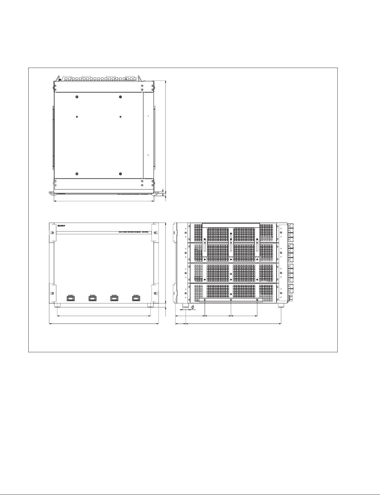
1-3-1. MVS-8000X
497
7
440
410.8
482
10
443.6 (10U)17.5
26
129.5 115.5115.5
45.2 420.4
Unit : mm
MVS-8000X/7000X
1-3
1-3-2. MVS-7000X
497
7
440
410.8 129.5 115.5 115.5
482
10
26
17.5 354.7 (8U)
45.2 420.4
Unit: mm
1-4
MVS-8000X/7000X

1-4. Installing the Options
MVS-7000X Option List
The MVS-8000X-C/MVS-7000X-C is shipped from the
factory with the necessary option boards (refer to the
following table) already installed in accordance with the
specifi ed system confi guration.
The following options are available for the MVS-8000X/
MVS-7000X.
MVS-8000X Option List
Name of option Board confi guration
Plug-in board
(Front)
MKS-8110X
20 Input Board
MKS-8160X
Output Board Set
MKS-8170X
DME Interface Board Set
MKS-8180X
Cross Point Board Set
MKS-8210X
Mix/Effect Board
MKS-8440X
Frame Memory Board Set
MKS-8450X
Format Converter Board
HK-PSU05
Power Supply Unit
BZS-8200X
Multi Program 2 Software
BZS-8420X
Color Correction Software
BZS-8560X
Switcher Upgrade Software
*1: Currently M/E4 is not supported.
*1
_
OUT-35A board CNO-38 board
XPT-32 board CNI-37 board
XPT-31A board CNI-37 board
MIX-53 board
MY-118 board CN-3235 board
FC-112 board
__
__
__
__
Connector
board (Rear)
CNI-37 board
CNO-37 board
_
_
Name of option Board confi guration
MKS-7171X
DME Output Connector Board
MKS-7210X
Mix/Effect Board
MKS-7470X
DME Board Set
MKS-7471X
Additional DME Board
MKS-8110X
20 Input Board
MKS-8160X
Output Board Set
MKS-8440X
Frame Memory Board Set
MKS-8450X
Format Converter Board
HK-PSU05
Power Supply Unit
BZS-7200X
Multi Program 2 Software
BZS-7420X
Color Correction Software
BZS-7500X
Switcher Upgrade Software
BZS-7510X
Switcher Upgrade Software
BZS-7520X
Switcher Upgrade Software
BZS-7530X
Switcher Upgrade Software
BZS-7540X
DME Upgrade Software
BZS-7541X
DME Upgrade Software
BZS-7560X
Switcher Upgrade Software
BZS-7561X
DME Upgrade Software
Plug-in board
(Front)
_
MIX-53 board
DVP-53 board
XPT-32 board
DVP-53 board
_
OUT-35A board CNO-38 board
MY-118 board CN-3235 board
FC-112 board
__
__
__
__
__
__
__
__
__
__
__
Connector
board (Rear)
CNO-37 board
_
_
_
CNI-37 board
_
MVS-8000X/7000X
1-5

1-4-1. Installing the Plug-in Boards
c
Be sure to turn off the POWER switch before starting
installation work.
If installation work is started with the POWER switch left
on, it may cause electrical shock or damage to printed
circuit boards.
Each plug-in board of the Production Switcher Processor
MVS-8000X/MVS-7000X is allocated to a specifi c slot
into which they must be installed. Check to see that the
respective plug-in boards are installed in their respective
slots.
The name of the board is shown near the eject lever at the
right-most end of each plug-in board.
Names of the plug-in boards and the slot numbers, to which
the plug-in boards are allocated, are shown on the
Extract PWB stopper assembly inside the front panel of the
MVS-8000X Install the respective plug-in boards according to this instruction.
c
. Check to see that connectors of the plug-in boards are
securely inserted into the mother board (MVS-8000X:
MB-1150 board, MVS-7000X: MB-1151 board) without
loose contact.
If any plug-in board is inserted into the incorrect slot, it
causes a system error and the system will not work
correctly.
. After installing the plug-in board, the software must be
installed. Install the software same version as the MVS8000X/MVS-7000X.
For installing the software, refer to the user’s guide of
the MVS-8000X/MVS-7000X system.
Installation Procedure
1. Turn off the main power of this unit (MVS-8000X)
and disconnect the AC power cord from the wall outlet.
2. Loosen the four screws (with drop-safe) and remove
the front panel to the arrow.
This figure shows MVS-8000X
Screw (with
drop-safe)
Screw (with
Front panel
drop-safe)
3. Push the black panel lock toward the (1) direction to
unlock, pull the knob toward the (2) direction an
remove the blank panel.
n
Store the removed blank panel in a safe place.
This figure shows MVS-8000X
1-6
Blank panel
Lock
1
2
Knob
MVS-8000X/7000X

4. While the eject levers are opened as shown in the illustration, insert the plug-in board into the board guide rail.
n
While the eject levers are opened as shown in the illus-
tration, insert the plug-in board into the board guide rail.
This figure shows MVS-8000X
Board guide rail
Board guard
Short Rib
Long Rib
MVS-8000X Option List
Name of option Name of board Slot on the front side
MKS-8160X OUT-35A board 14
MKS-8170X XPT-32 board 3
MKS-8180X XPT-31A board 6
*1
MKS-8210X
MIX-53 board 1, 2, 4
MKS-8440X MY-118 board 16
MKS-8450X FC-112 board 11, 12
*1: Installation order of MIX-53 board
First board: Slot no. 8 (standard)
Second board: Slot no. 7 (standard)
Third board: Slot no. 4 (option)
Fifth board: Slot no. 2 (option)
Sixth board: Slot no. 1 (option)
MVS-7000X Option List
Name of option Name of board Slot on the front side
MKS-7210X *1 MIX-53 board 5, 6, 9
MKS-7470X DVP-53 board 3
XPT-32 board 4
MKS-7471X DVP-53 board 2
MKS-8160X OUT-35A board 12
MKS-8440X MY-118 board 13
MKS-8450X FC-112 board 10
Eject lever
*1: Installation order of MIX-53 board
First board: Slot no. 9 (option)
Second board: Slot no. 6 (option)
Third board: Slot no. 5 (option)
MVS-8000X/7000X
1-7

5. Close the both eject levers at a time, when the eject
lever claws reach the A position (1).
And push the eject levers (2) until the unlock buttons
pop out.
1-4-2. Installing the Connector Board
Service Tool
Lever unlock jig : Part No. 4-193-124-01
This figure shows MVS-8000X
1. Insert the protrusion of the lever unlock jigs into the
red groove of the blank panel's rear levers (1) and
while pushing the lever unlock jigs, open the rear
levers outward to unlock.
This figure shows MVS-8000X
Lever unlock jig
Lever unlock jig
Blank panel
A
Eject lever Eject lever
2
3
Eject lever
Unlock button Unlock button
11
2
A
3
Unlock button
1 1
Lever unlock jig
Rear leverRear lever
1-8
MVS-8000X/7000X

2. While the rear levers are opened, remove the blank
panel.
m
. Store the removed blank panel in a safe place.
. In case there is a blank panel consecutive in steps
above (in a unit), remove these blank panel too.
This figure shows MVS-8000X
In case there is a blank panel consecutive in steps
above (in a unit), remove these blank panel too.
Rear lever
Rear lever
Blank panel
4. Push the rear levers inward until a click sound is made
and they are locked.
This figure shows MVS-8000X
Rear lever
Rear lever
Unit
3. While the rear levers are opened as shown in the
illustration, insert the plug-in board into the board
guide rail.
n
Insert making sure the board's upper and lower spring
plates do not catch on the board.
This figure shows MVS-8000X
Spring plate
Plug-in board
MVS-8000X Option List
Name of option Name of board Slot on the rear side
MKS-8110X CNI-37 board 6, 7, 8, 9, 10, 11
MKS-8160X CNO-38 board 14
MKS-8170X CNI-37 board 1
CNO-37 board 2
MKS-8180X CNI-37 board 3
MKS-8440X CN-3235 board 16
MVS-7000X Option List
Name of option Name of board Slot on the rear side
MKS-7171X CNO-37 board 3
MKS-8110X CNI-37 board 2, 6, 7, 8
MKS-8160X CNO-38 board 10
MKS-8440X CN-3235 board 12
5. Install the blank panel removed once in the slot on one
step.
MVS-8000X/7000X
1-9
1-4-3. Installing the HK-PSU05
The HK-PSU05 is used after it is installed in the MVS8000X or the MVS-7000X.
n
Before installing the HK-PSU05, be sure to turn off the
main power. If the HK-PSU05 is installed while the main
power is turned on, it can result in electrical shock or
damage to printed circuit boards.
4. Push the unlock button, and open the eject lever.
5. Insert the HU-PSU05 into the slot, and push until the
eject lever claws catch the chassis.
Claw
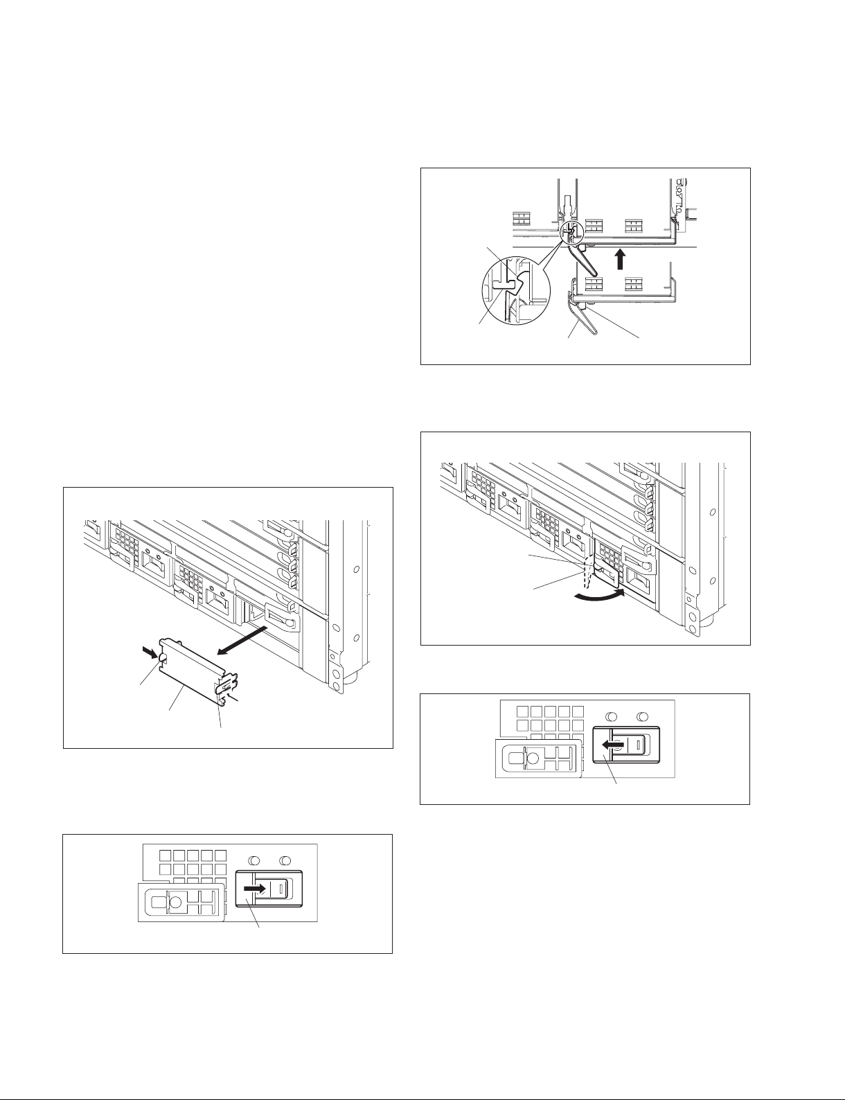
Installation procedure
1. Remove the front panel of the MVS-8000X/MVS7000X.
(Refer to Section 1-4-1.)
2. While pushing either of blank panel's knobs toward the
(1) position, remove by pulling toward the (2)
position.
This figure shows MVS-8000X
Left
1
Knob
Blank panel
2
Right
1
Knob
Chassis
Eject lever
Unlock button
6. Push the unlock button, as shown in the illustration it
is in the locked position.
This figure shows MVS-8000X
Unlock button
Eject lever
7. Slide the switch cover left to open.
3. Turn OFF the power switch and close the switch cover
by sliding it right. If the switch is ON, the switch cover
will not slide and the unlock button cannot be pressed.
Switch cover
1-10
Switch cover
1-4-4. Installing the Software Options
For the installation procedure of the software options
BZS-8200X/8420X/8560X/7200X/7420X/7500X/7510X/
7520X/7530X/7540X/7541X/7560X/7561X, refer to the
MVS-8000X/MVS-7000X System User’s Guide.
MVS-8000X/7000X

1-5. Rack Mounting
Rack Mounting Procedure
The MVS-8000X/MVS-7000X is mounted in the 19-inch
standard rack.
Precautions for Rack Mounting
w
. To prevent the rack from falling or moving, fi x the rack
on a fl at and steady fl oor and the like using bolts or
others. If the rack falls due to the weight of the equipment, it may cause death or serious injury.
. Be sure to use the rack mount parts (supplied with MVS-
8000X). If not, injury may result and the equipment may
fall due to insuffi cient strength.
. After rack mounting, be sure to tighten the screws on the
rack angle and fi x the unit in the rack. If the screws on
the rack angle are not tightened, the unit may slip from
the rack and fall, causing injury.
w
When mounting the unit in the rack, note the following:
. Be sure to mount in the rack with two persons or more.
. Be careful not to catch your fi ngers or hands in the rack
mount rail or others.
. Hold the bottom of unit and mount in the rack in a stable
position.
w
If several units are mounted in a rack, it is recommended to
install a ventilation fan to prevent temperature rise inside
the rack.
1. Loosen the four screws (+B4 x 8) and remove the four
feet.
Feet
+B4 s8
Feet
+B4 s8
2. Remove the front panel of the equipment.
(Refer to Section 1-4-1.)
3. Attach the rack tool to the side of the equipment using
the specifi ed six screws.
n
Use +B4 x 6 screws. Tighten the screws to the follow-
ing torque.
Tightening torque : 120 x 10_2 N.m {12.2 kgf . cm}
+B4 s6
Rack tool
1-5-1. MVS-8000X
To mount the MVS-8000X in the rack, use the rack mount
parts (supplied with MVS-8000X) and follow the procedure described below.
n
If other than the rack mount parts (supplied with MVS8000X) is used, the unit may not be mounted in the 19-inch
standard rack.
Using parts list (Accessory of the MVS-8000X)
. Rack tool 2pcs
. Support angle 2pcs
. Bracket 4pcs
. Rack tool attaching screw
(+B4 x 6 : 7-682-560-04) 6pcs
. Support angle attaching screw
(+PSW4 x 10 : 7-682-962-01) 8pcs
. Bracket attaching screw
(+B4 x 10 : 7-682-562-04) 8pcs
Other required parts
. Screw for rack mounting
(+B5 x 12 : 7-682-576-09) 4pcs
MVS-8000X/7000X
Rack tool
+B4 s6
1-11
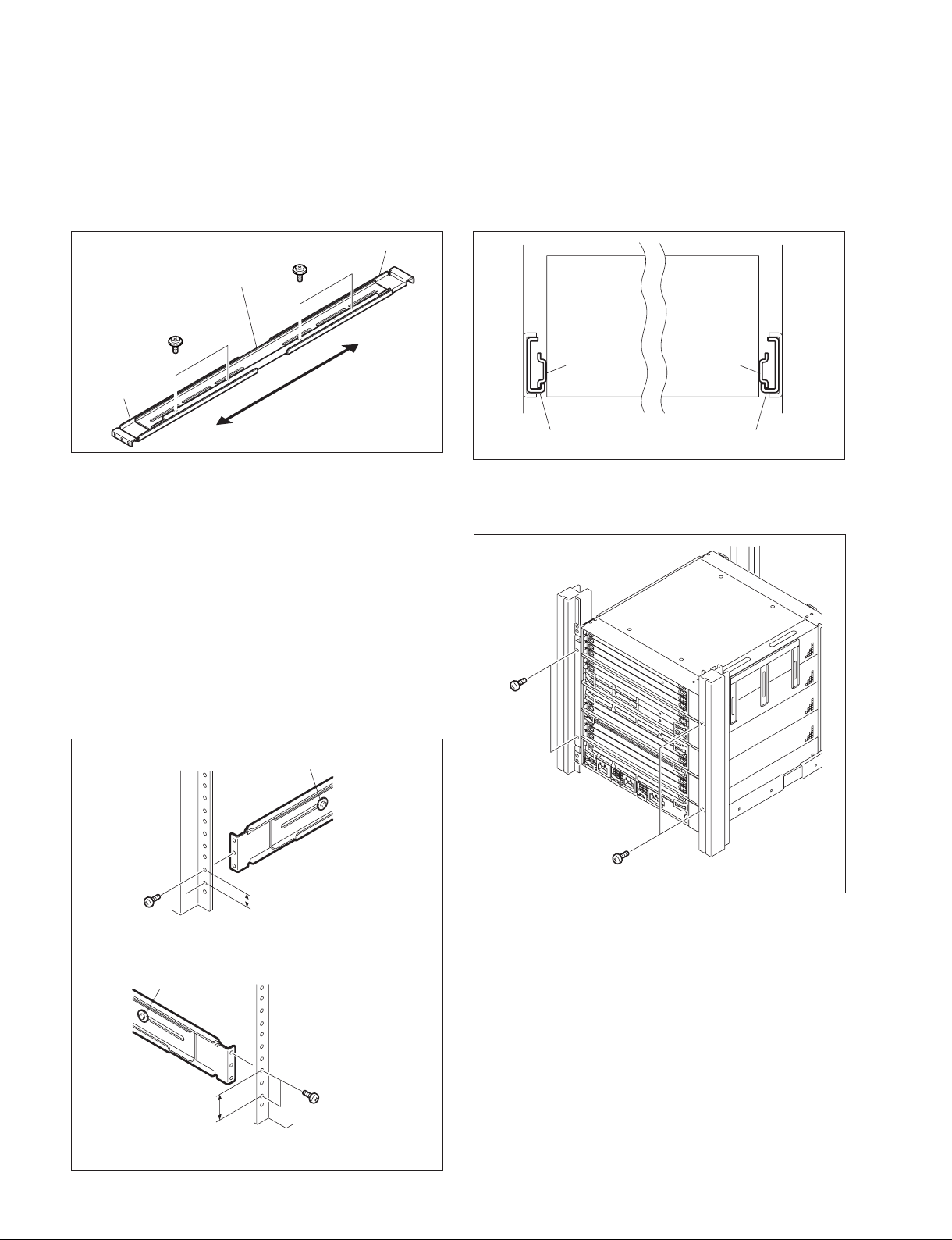
4 Attach the bracket to the support angle by inserting the
specifi ed four screws and loosely tightening.
5. Loosen the screws on the rear of the right and left
adapters and adjust the length of the adapter accordin
to the depth of the rack.
8. Align the groove of the rack tool at the side of the
equipment with the rail, and slide the equipment to the
rear.
n
The rack tools are hooked on the rails as shown below.
+PSW4 s10
Bracket
Support angle
+PSW4 s10
Bracket
n
Maximum depth of bracket : 750 mm
Minimum depth of bracket : 545 mm
6. Attach the right and left adapters to the rack completely using the specifi ed eight screws.
(The illustration below shows the left adapter.)
7. Tighten the screws (+PSW4 x 10 : four screws each
on the right and left) for adjusting the length of the
adapter completely (the screws that were loosened in
step 5).
Rack tool Rack tool
Support angle Support angle
9. Fix the rack angle in the rack using the specifi ed
screws.
+B5 s12
1-12
Front side
+B4 s10
Rear side
+PSW4 s10
31.75
+PSW4 s10
+B5 s12
15.9
10. Attach the front panel to the equipment.
(Refer to Section 1-4-1.)
+B4 s10
Unit:mm
MVS-8000X/7000X
 Loading...