

Sony HK-PSU02, HK-PSU11, MKS-2010, MKS-2015, MKS-2017 Installation Manual
...
SWITCHER PROCESSOR PACK
MFS-2000-C
MULTI FORMAT SWITCHER PROCESSOR
MFS-2000
HK-PSU02 HK-PSU11
MKS-2010 MKS-2015 MKS-2017
MKS-2110M MKS-2420M MKS-2440
MKS-2470
BZS-2000M BZS-2440M BZS-2470M
INSTALLATION MANUAL
1st Edition (Revised 2)

! WARNING
This manual is intended for qualified service personnel only.
To reduce the risk of electric shock, fire or injury, do not perform any servicing other than that
contained in the operating instructions unless you are qualified to do so. Refer all servicing to
qualified service personnel.
! WARNUNG
Die Anleitung ist nur für qualifiziertes Fachpersonal bestimmt.
Alle Wartungsarbeiten dürfen nur von qualifiziertem Fachpersonal ausgeführt werden. Um die
Gefahr eines elektrischen Schlages, Feuergefahr und Verletzungen zu vermeiden, sind bei
Wartungsarbeiten strikt die Angaben in der Anleitung zu befolgen. Andere als die angegeben
Wartungsarbeiten dürfen nur von Personen ausgeführt werden, die eine spezielle Befähigung
dazu besitzen.
! AVERTISSEMENT
Ce manual est destiné uniquement aux personnes compétentes en charge de l'entretien. Afin de
réduire les risques de décharge électrique, d'incendie ou de blessure n'effectuer que les
réparations indiquées dans le mode d'emploi à moins d'être qualifié pour en effectuer d'autres.
Pour toute réparation faire appel à une personne compétente uniquement.
MFS-2000 Serial No. 10001 and Higher
MKS-2010 Serial No. 10001 and Higher
MKS-2015 Serial No. 10001 and Higher
MKS-2017 Serial No. 10001 and Higher
MKS-2110M Serial No. 10001 and Higher
MKS-2420M Serial No. 10001 and Higher
MKS-2440 Serial No. 10001 and Higher
MKS-2470 Serial No. 10001 and Higher
HK-PSU02 Serial No. 10001 and Higher
HK-PSU11 Serial No. 10001 and Higher
BZS-2000M
BZS-2440M
BZS-2470M
MFS-2000 IM
Attention-when the product is installed in Rack:
For MKS-2010/2015/2017
1. Prevention against overloading of branch circuit
When this product is installed in a rack and is
supplied power from an outlet on the rack, please
make sure that the rack does not overload the supply
circuit.
2. Providing protective earth
When this product is installed in a rack and is
supplied power from an outlet on the rack, please
confirm that the outlet is provided with a suitable
protective earth connection.
3. Internal air ambient temperature of the rack
When this product is installed in a rack, please make
sure that the internal air ambient temperature of the
rack is within the specified limit of this product.
4. Prevention against achieving hazardous
condition due to uneven mechanical loading
When this product is installed in a rack, please make
sure that the rack does not achieve hazardous
condition due to uneven mechanical loading.
5. Install the equipment while taking the operating
temperature of the equipment into consideration
For the operating temperature of the equipment, refer
to the specifications of the Operation Manual.
WARNING
This unit has no power switch.
When installing the unit, incorporate a readily
accessible disconnect device in the fixed wiring, or
connect the power cord to a socket-outlet which must be
provided near the unit and easily accessible, so that the
user can turn off the power in case a fault should occur.
WARNUNG
Dieses Gerät hat keinen Netzschalter.
Beim Einbau des Geräts ist daher im Festkabel ein
leicht zugänglicher Unterbrecher einzufügen, oder das
ß
Netzkabel mu
befindlichen, leicht zugänglichen Wandsteckdose
verbunden werden, damit sich bei einer
Funktionsstörung die Stromversorgung zum Gerät
jederzeit unterbrechen lä
For the customers in the Netherlands
Voor de klanten in Nederland
Hoe u de batterijen moet verwijderen, leest u in de
Onderhoudshandleiding.
Gooi de batterij niet weg maar lever deze in als klein
chemisch afval (KCA).
mit einer in der Nähe des Geräts
ß
t.
6. When performing the installation, keep the
following space away from walls in order to
obtain proper exhaust and radiation of heat.
. MFS-2000
Front, Right, Left : 10 cm (4 inches) or more
. MKS-2010/2015
Front, Back, Right, Left : 10 cm (4 inches) or more
. MKS-2017
Front, Back, Right : 10 cm (4 inches) or more
For safety, do not connect the connector for peripheral
device wiring that might have excessive voltage to the
following port(s).
MFS-2000
: SWITCHER DATA connector
: DME DATA (Digital Multi Effect Data) connector
: SWITCHER CTRL (switcher control) connector
: DME CTRL (Digital Multi Effect control) connector
MKS-2010/2015/2017
: PERIPH (peripheral) connector
: CTRL (control) connector
: DATA connector
MKS-2440
: FM DATA connector
Follow the instructions for the above port(s).
Für Kunden in Deutschland
Entsorgungshinweis: Bitte werfen Sie nur entladene
Batterien in die Sammelboxen beim Handel oder den
Kommunen. Entladen sind Batterien in der Regel dann,
wenn das Gerät abschaltet und signalisiert “Batterie
leer” oder nach längerer Gebrauchsdauer der Batterien
“nicht mehr einwandfrei funktioniert”. Um
sicherzugehen, kleben Sie die Batteriepole z.B. mit
einem Klebestreifen ab oder geben Sie die Batterien
einzeln in einen Plastikbeutel.
MFS-2000 IM
1 (P)


Table of Contents
Manual Structure
Purpose of this manual .............................................................................................. 3
Related manuals ......................................................................................................... 3
Trademarks ................................................................................................................ 3
Contents ..................................................................................................................... 4
1. Preparation for Installation
1-1. Operating Environment ...............................................................................1-1
1-2. Power Supply .............................................................................................. 1-1
1-2-1. Power Specifications ..................................................................1-1
1-2-2. Recommended Power Cord ........................................................ 1-2
2. Installation of the Processor
2-1. External Dimensions ................................................................................... 2-1
2-2. Removing/Reinstalling Front Panel ............................................................ 2-2
2-3. Installing the Options .................................................................................. 2-2
2-3-1. Installing Plug-in Boards ............................................................ 2-3
2-3-2. Installing Connector Board ........................................................ 2-4
2-3-3. Installing HK-PSU02 ................................................................. 2-4
2-3-4. Installing BZS-2000M/2440M/2470M ...................................... 2-4
2-3-5. Installing MKS-2420M .............................................................. 2-5
2-4. Rack Mounting the Processor ..................................................................... 2-6
2-5. Description of On-board Switches and LEDs .............................................2-8
3. Installation of the Control Panel
3-1. Installation Space ........................................................................................ 3-1
3-1-1. External Dimensions .................................................................. 3-1
3-1-2. Installation Space ....................................................................... 3-4
3-2. Removing/Reinstalling Front Panel ............................................................ 3-7
3-3. Installing the Options .................................................................................. 3-8
3-3-1. Installing HK-PSU11 ................................................................. 3-8
3-4. Description of On-board Switches and LEDs ...........................................3-10
3-5. Installing on the Control Console .............................................................3-11
3-5-1. MKS-2010 ................................................................................3-11
3-5-2. MKS-2015/2017 ....................................................................... 3-13
MFS-2000 IM
1

4. Connection
4-1. Matching Connectors and Cables................................................................ 4-1
4-2. Input/Output Signals of Connectors ............................................................ 4-2
4-3. System Connection...................................................................................... 4-5
4-4. Setup ............................................................................................................ 4-6
5. Service Overview
5-1. Troubleshooting .......................................................................................... 5-1
5-1-1. Processor .................................................................................... 5-1
5-1-2. Control Panel .............................................................................. 5-2
5-2. Periodic Inspection and Maintenance ......................................................... 5-3
5-2-1. Cleaning .....................................................................................5-3
5-3. Data Backup Capacitor ...............................................................................5-4
2
MFS-2000 IM

Purpose of this manual
Related manuals
Manual Structure
This manual is the installation manual of Switcher Processor Pack MFS-2000-C and
its optional boards and units.
This manual is intended for use by trained system and service engineers, and
describes the information on installing the MFS-2000-C system.
The MFS-2000 is described as the processor, and the MKS-2010/2015/2017 are
described as the control panel in this manual.
The following manuals are prepared for MFS-2000-C and its optional boards and
units.
..
. Operation Manual (Supplied with MFS-2000-C)
..
This manual describes the application and operation of MFS-2000-C system.
..
. User’s Guide (Supplied with MFS-2000-C)
..
This manual is required for detailed application and operation of the MFS-2000-C
system.
Trademarks
..
. Maintenance Manual (Available on request)
..
This manual describes the detailed service information.
If this manual is required, please contact your local Sony Sales Office/Service
Center.
..
. “Semiconductor Pin Assignments” CD-ROM (Available on request)
..
This “Semiconductor Pin Assignments” CD-ROM allows you to search for
semiconductors used in B&P Company equipment.
Semiconductors that cannot be searched for on this CD-ROM are listed in the
maintenance manual for the corresponding unit. The maintenance manual contains
a complete list of all semiconductors and their ID Nos., and thus should be used
together with the CD-ROM.
Part number: 9-968-546-XX
Trademarks and registered trademarks used in this manual are follows.
. Memory Stick is a trademark of Sony Corporation.
. Ethernet is a registered trademark of Xerox Corporation.
Other system names and the product names described in this manual are trademarks
or registered trademarks of their respective holders.
MFS-2000 IM
3

Contents
This manual is organized by following sections.
Section 1 Preparation for Installation
Describes the circumstance of use and power of the processor and control panel.
Section 2 Installation of the Processor
Describes the processor’s installation information (removal/installation of the front
panel, the installation of the options, the rack mounting, the settings of the on-board
switch and the function of LED).
Section 3 Installation of the Control Panel
Describes the control panel’s installation information (installation space, the removal/installation of the front panel, the installation of the options, and the settings of
the on-board switch and the function of LED).
Section 4 Connection
Describes the processor’s and control panel’s connection information (matching
connectors/cables, the I/O signals of the connector, the example of the system
connection).
Section 5 Service Overview
Describes the troubleshooting of the processor and the control panel, the periodic
inspection, and the capacitor for backing up the data.
4
MFS-2000 IM

Section 1
Preparation for Installation
1-1. Operating Environment
Operating guaranteed temperature : +5 dC to +40 dC
Performance guaranteed temperature : +10 dC to +35 dC
Operating humidity : 10 % to 90 %
(relative humidity)
Storage temperature : _20 dC to +60 dC
Mass (when all options are installed) :
MFS-2000 : Approx. 22 kg
MKS-2010 : Approx. 10.3 kg
MKS-2015 : Approx. 11.3 kg
MKS-2017 : Approx. 12.6 kg
Prohibited locations for installation
. Areas where the unit will be exposed do direct sunlight
or any other strong lights
. Dusty areas
. Areas subject to vibration
. Areas with strong electric or magnetic fields
. Areas near heat sources
. Areas subject to electrical noise
. Areas subject where is subjected to static electricity
Ventilation of the processor
The inside of the processor is cooled by a fan (on both
sides).
The power supply can be damaged if the exhaust vent (on
both sides) and air intake (on the front panel) are blocked
or the fan is stopped.
Therefore, leave room of more than 10 cm in the front and
both sides of the processor.
Ventilation of the control panel
The inside of the control panel is cooled by a fan (on the
side).
The power supply can be damaged if the exhaust vent and
air intake (on both sides and the rear) are blocked or the
fan is stopped.
Therefore, leave room of more than each 10 cm in the
front, back, right and left sides. (There is no need of
leaving room on the left side of the MKS-2017.)
When you install the control panel to the rack, be sure not
to block the exhaust vent/air intake on the sides of the
control panel.
1-2. Power Supply
w
There is no power switch on the control panel.
Set the dedicated breaker.
1-2-1. Power Specifications
The switching regulator is used for the power of the
processor and the control panel. The voltage within the
range of 100 V to 240 V can be used without changing the
supply voltage.
Power requirements : AC 100 - 240 V
Power frequency : 50/60 Hz
Current consumption (when all options are installed) :
MFS-2000 : 4.5 - 2.1 A
MKS-2010 : 1.0 - 0.5 A
MKS-2015 : 1.0 - 0.5 A
MKS-2017 : 1.0 - 0.6 A
m(Processor)
. As the inrush current at turn-on is a maximum 12 A (at
100 V)/33 A (at 230 V), the capacity of the AC power
source must be commensurate with this load.
If the capacity of the AC power is not adequately large,
the AC power source breaker will operate or the unit will
abnormally operate.
. The processor contains the two power supply units as the
standard configuration. A maximum of three power
supply units may be installed. When starting up the
processor, be sure to turn on the power of two or more
power supply units.
n(Control panel)
. As the inrush current at turn-on is a maximum 12 A (at
100 V)/28 A (at 230 V), the capacity of the AC power
source must be commensurate with this load.
If the capacity of the AC power is not adequately large,
the AC power source breaker will operate or the unit will
abnormally operate.
MFS-2000 IM
1-1

1-2-2. Recommended Power Cord
Neither the processor nor control panel come with a power
cord.
To get a power cord, please contact your local Sony Sales
Office/Service Center.
w
. Use the approved Power Cord (3-core mains lead)/
Appliance Connector/Plug with earthing-contacts that
conforms to the safety regulations of each country if
applicable.
. Use the Power Cord (3-core mains lead)/Appliance
Connector/Plug conforming to the proper ratings (Voltage, Ampere).
If you have questions on the use of the above Power Cord/
Appliance Connector/Plug, please contact your local Sony
Sales Office/Service Center.
w
. Never use an injured power cord.
. Plugging the power cord in the AC inlet, push as far as it
will go.
For customers in the U.S.A. and Canada
1 Power cord, 125 V 10 A (2.4 m) : ! 1-557-377-11
1
For customers in the all European countries
1 Power cord, 250 V 10 A (2.4 m) : ! 1-782-929-21
1
AC inlet
AC inlet
1-2
MFS-2000 IM
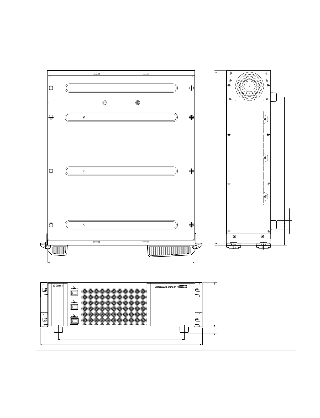
2-1. External Dimensions
Section 2
Installation of the Processor
B3B3
B3
440
520
380
φ26
61
132.417.5
4
MFS-2000 IM
375
482
Unit : mm
2-1
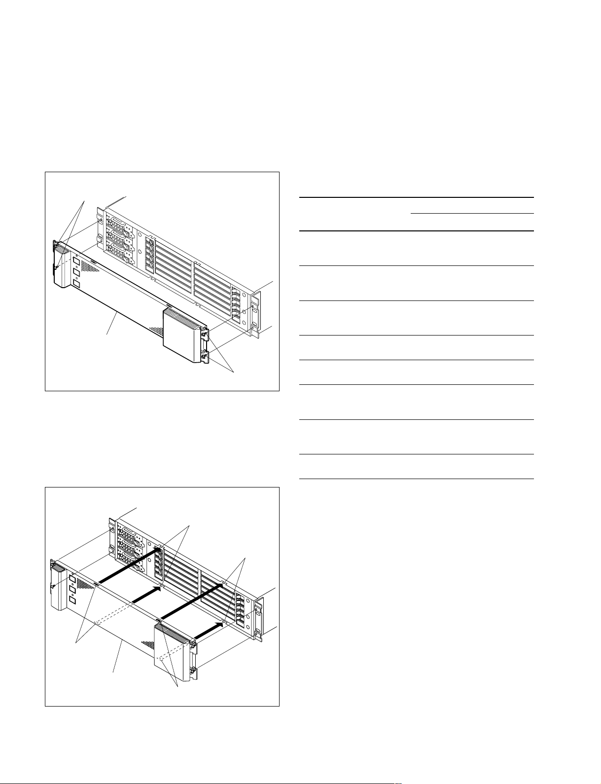
2-2. Removing/Reinstalling Front Panel
2-3. Installing the Options
Removal
1. Turn off the main powers of the processor and disconnect the AC power cords from the wall outlet.
2. Tighten the four screws (with drop-safe) and remove
the front panel.
Screws
(with drop-safe)
Front panel
Screws (with drop-safe)
Reinstallation
Insert the front panel securely into the chassis and tighten
the four screws (with drop-safe).
n
To install the front panel, fit the protrusions of the chassis
into the grooves in the front panel.
The MFS-2000-C is shipped from the factory with the
necessary option boards (refer to the following table)
already installed in accordance with the specified system
configuration.
The following options are available for the processor.
Option list for the processor
Model name Board configuration
Plug-in board
MKS-2110M _ CN-2486 board
INPUT/OUTPUT
CONNECTOR BOARD
MKS-2420M (CC-95 board*2) _
COLOR CORRECTOR
BOARD
MKS-2440 MY-112 board CN-2535 board
FRAME MEMORY
BOARD SET
MKS-2470 DVP-30 board _
DME BOARD SET CA-54CFB board
HK-PSU02 __
POWER SUPPLY UNIT
BZS-2000M
SWITCHER UPGRADE
SOFTWARE
BZS-2440M
FRAME MEMORY
UPGRADE SOFTWARE
BZS-2470M
DME UPGRADE SOFTWARE
*1 : BZS-2000M, BZS-2440M and BZS-2470M are the software options.
*2 : The CC-95 board is the option board to install on the MY-112 board.
*1
*1
*1
__
__
__
Connector board
2-2
Protrusions
Protrusions
Grooves
Front panel
Grooves
MFS-2000 IM
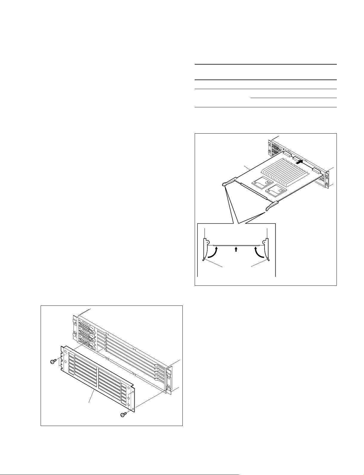
2-3-1. Installing Plug-in Boards
Eject levers
Plug-in board
11
Each plug-in board is allocated to a specific slot into which
they must be installed. Check that the respective plug-in
boards are installed in their respective slots.
The name of the board is shown near the eject lever at the
left-most end of each plug-in board.
Names of the plug-in boards and the slot numbers, to
which the plug-in boards are allocated, are shown on the
board retainer inside the front panel of the processor.
Install the respective plug-in boards according to this
instruction.
m
. If any plug-in board is inserted into the incorrect slot, it
causes a system error and the system will not work
correctly.
. Check that the connectors of the plug-in boards are
securely inserted into the mother board (MB-1021
board) without loose contact.
c
Be sure to turn off the POWER switches before starting
installation work.
If installation work is started with the POWER switch left
on, it may cause electrical shock or damage to printed
circuit boards.
4. While holding the eject levers open, insert the plug-in
board into the board guide rails.
Option model name Board name
MKS-2440 MY-112 board 6
MKS-2470 DVP-30 board 1
CA-54CF board 2
Installation slot
(front side)
5. Push in the plug-in board and close the eject levers in
the direction of arrow 1.
Installation
1. Turn off the main powers of the processor and discon-
2. Remove the front panel. (Refer to Section 2-2.)
3. Remove the four screws and remove the board retainer.
nect the AC power cords from the wall outlet.
B3 x 5
Board retainer
B3 x 5
6. Attach the
board retainer
and the front panel by revers-
ing the installation steps of 2 and 3.
n
After installing the plug-in board, the software must be
installed. Install the software of V2.20 or later version.
For installing the software, refer to the user’s guide of
the MFS-2000 system.
MFS-2000 IM
2-3
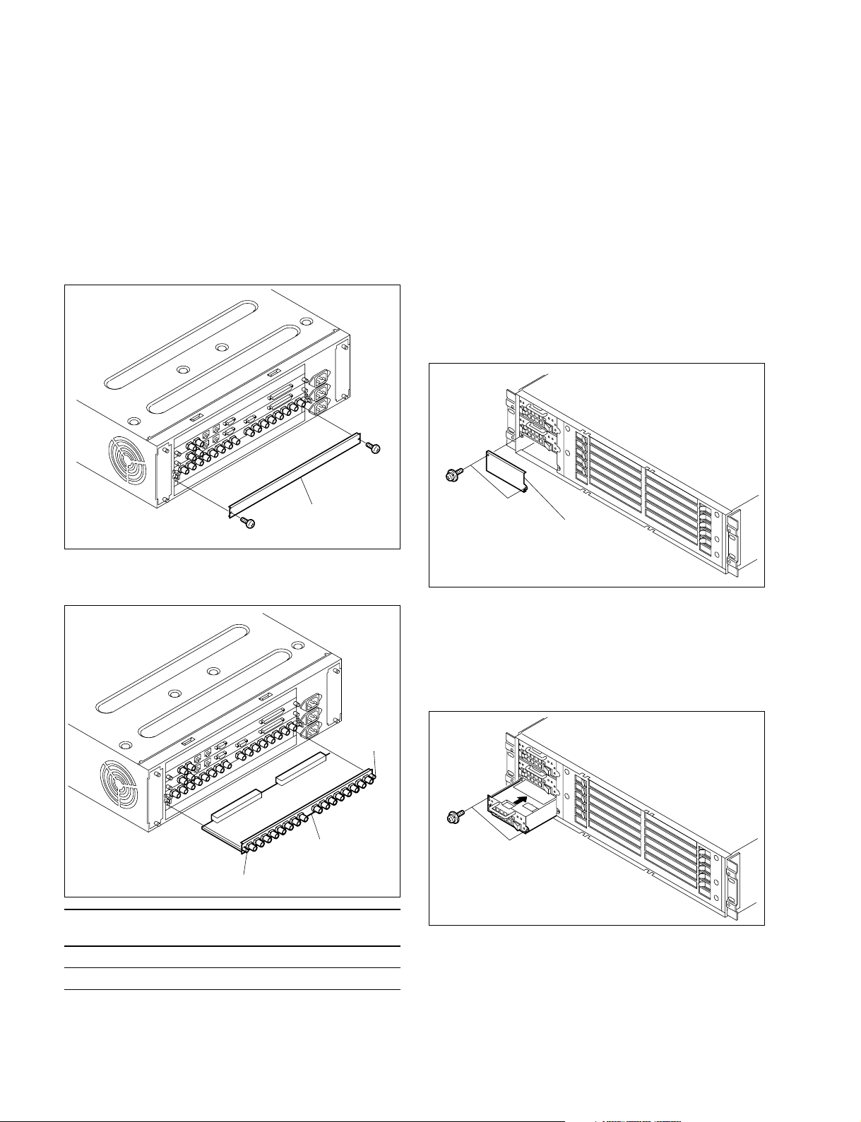
2-3-2. Installing Connector Board
2-3-3. Installing HK-PSU02
1. Remove the two screws and remove the blank panel.
m
. To install the connector board into the slot in which
the other board is installed already, loosen the two
fixing screws and remove the connector board
installed already.
. Store the removed blank panel in a safe place.
B3 x 5
Blank panel
B3 x 5
The HK-PSU02 is used in the processor.
c
Before installing an HK-PSU02 in processor, set the
POWER switch of the HK-PSU02 to the “O” position
(OFF).
1. Turn off the main powers of the processor and disconnect the AC power cords from the outlet.
2. Remove the front panel. (Refer to Section 2-2.)
3. Remove the two screws that secure the blank panel
and remove the blank panel.
PSW3 x 6
Blank panel
2. Insert the connector board horizontally level and
secure it with the two fixing screws.
Fixing screw
Connector board
Fixing screw
Option model name Board name
MKS-2110M CN-2486 board 5
MKS-2440 CN-2535 board 6
Installation slot
(rear side)
n
Store the removed blank panel in a safe place.
4. Insert the HK-PSU02 securely into the deep end.
5. Secure the HK-PSU02 with the two screws, which are
removed in the step 3.
PSW3 x 6
6. Reinstall the front panel.
2-3-4. Installing BZS-2000M/2440M/2470M
2-4
For the installation procedure of the software options BZS2000M/2440M/2470M, refer to the MFS-2000 System
User’s Guide.
MFS-2000 IM
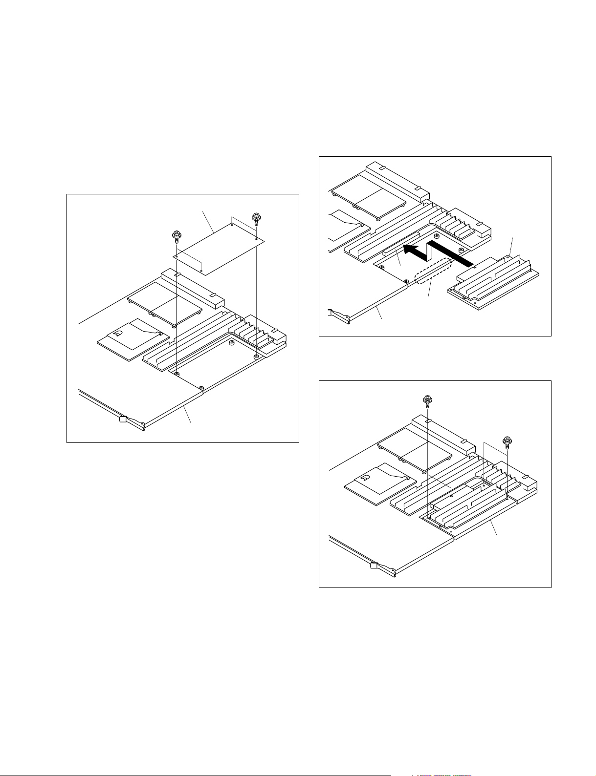
2-3-5. Installing MKS-2420M
CN1
MY-112 board
CC-95 board
A portion
MKS-2420M is used while being mounted on MKS-2440
(the MY-112 board).
n
Store the removed blank panel in a safe place.
1. Remove the four screws, and remove the blank panel
mounted on the MY-112 board.
2. Connect the CC-95 board to the connector (CN1) on
the MY-112 board.
n
Install the CC-95 board carefully to prevent the
mounted parts on the backside of the CC-95 board
from being caught by the A portion.
Blank panel
PSW3 x 5
MY-112 board
PSW3 x 5
3. Secure the CC-95 board with the four screws removed
in step 1.
PSW3 x 5
PSW3 x 5
MFS-2000 IM
CC-95 board
2-5
2-4. Rack Mounting the Processor
The processor installs in a 19-inch standard rack.
To mount the processor in a rack, use the specified rack
mount kit and follow the procedure described below.
Specified rack mount kit : RMM-10
n
If a rack mount kit other than the specified one is used, the
unit may not correctly install in a 19-inch standard rack.
Parts of the RMM-10
. Rack tools 2 pcs
. Right rack mount adaptor 1 pc
. Left rack mount adaptor 1 pc
. Rack tool attaching screws 6 pcs
(B4 x 6 : 7-682-560-09)
. Adaptor attaching screws 6 pcs
(B4 x 10 : 7-682-560-10)
Precautions for rack mounting
w
. To prevent the rack from falling or moving, fix the rack
on a flat and steady floor using bolts or other fixings.
If the rack falls due to the weight of the equipment, it
may cause death or injury.
. Be sure to use the specified rack mount kit.
If not, injury may result and the equipment may fall due
to insufficient strength.
. After rack mounting, be sure to tighten the screws on the
rack angle and fix the unit in the rack.
Rack mounting procedure
This section describes the rack mounting procedure using
the RMM-10 rack mount kit.
n
Tighten the screws to the following torque.
Tightening torque : 120 x 10_2 N.m (12.2 kgf.cm)
1. Remove four feet as required.
Foot
B4 x 8
Foot
B4 x 8
2. Attach the rack tools to the side of the equipment using
the specified six screws.
n
Use B4 x 6 screws.
Rack tool
B4 x 6
c
When mounting the unit in the rack, note the following:
. Be sure to mount in the rack with two persons or more.
. Be careful not to catch your fingers or hands in the rack
mount rail or others.
. Mount in the rack in a stable position.
n
If several units are mounted in a rack, it is recommended
that a ventilation fan is installed to prevent temperature rise
inside the rack.
2-6
B4 x 6
Rack tool
MFS-2000 IM
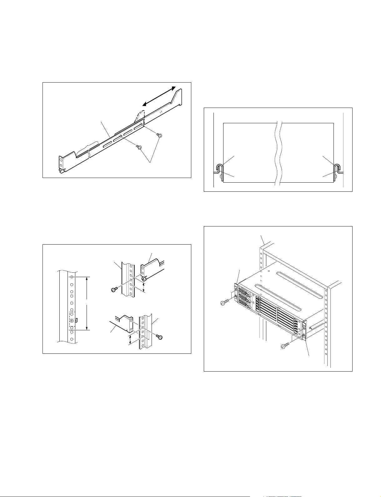
3. Loosen the screws on the rear of the right and left
adaptors and adjust the length of the adaptor according
to the depth of the rack.
(The illustration below shows the left adaptor.)
Adaptor
Portion of the rail
5. Tighten the screws (B4 x 6 : two screws each on the
right and left) for adjusting the length of the adaptor
completely (the screws that were loosened in step3).
6. Align the groove of the rack tool at the side of the equipment with the rail, and slide the equipment to the rear.
n
The rack tools are hooked on the rails as shown below.
B4 x 6
n
Maximum depth of adaptor : 750 mm
Minimum depth of adaptor : 595 mm
4. Attach the right and left adaptors to the rack completely using the specified six screws.
(The illustration below shows the left adaptor.)
Adaptor
Rack
B4 x 10
3U
Adaptor
31.75
31.75
Rack
B4 x 10
Unit : mm
Rack tool
Rail Rail
Rack tool
7. Remove the front panel. (Refer to Section 2-2.)
8. Fix the rack angles in the rack using the specified
screws.
Rack
Rack angle
B5 x 12
B5 x 12
Rack angle
MFS-2000 IM
9. Attach the front panel to the equipment.
2-7
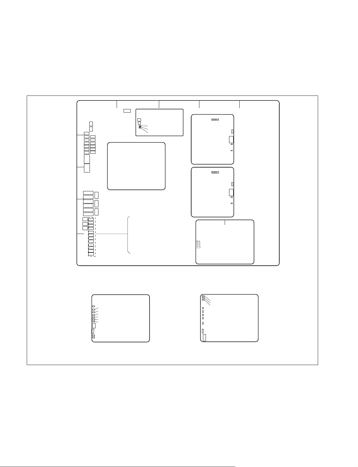
2-5. Description of On-board Switches and LEDs
n
The number shown in the parentheses ( ) indicates the address on the circuit board.
1. CA-54 board
AB C D E
D4
D5
D1303
D601
D602
D704
D701
ND101
ND102
ND901
ND902
ND1101
ND1102
S104
S901
S1101
ABCDEFG
1
S402
S401
D409
D410
D1002
D1001
D1201
2
D1202
S102
S103
S403
MAIN CPU
Module
S500
S300
*
D202
D201
D200
SIO-26
3
S101
S902
4
5
S1102
D101
D102
D103
D104
D901
D902
D903
D904
D1101
D1102
D1103
D1104
1
2
F
3
E
4
D
C
B
A
F
E
D
C
B
A
12345
DI2
DI3
CPU-DK
Module
(COM CPU-1)
12345
DI2
DI3
CPU-DK
Module
(COM CPU-2)
12
A
D100
D101
D200
B
DI6
DI6
DI7
SW2
DI7
SW2
DI8
SW1
DI4
DI1
DI8
SW1
DI4
DI1
SG-272
**
* : The CPU-DR module or CPU-DT module is used in the Main CPU module.
**
CPU-DR Module
B
A
D12
D18
D19
D14
D15
D1
6
D17
SW2
SW1
D1
0
D1
3
C
654321
G
F
E
D
CPU-DT Module
C
B
A
D11
D13
D14
D18
D17
D16
D15
D19
SW1
SW2
E
D
G
F
654321
A side/Component side
2-8
MFS-2000 IM
 Loading...