

Sony BVT-2000 Operation And Maintenance Manual

SONY:
1
DIGITAL
TIME
BASE
CORRECTOR
BVT-2000
•
.
.
.....
OPERATION
AND
MAINTENANCE MANUAL

TABLE OF CONTENTS
1.
OPERATION
FEATURES
1-1.
SPECIFICATIONS
1-2.
1-2-1. General . . . . . . . . . . . . . . . . . . . . . . . . . . .
1-2-2. Video . . . . . . . . . . . . . . . . . . . . . . . . . . . .
1-2-3. Input signal s
Output
1-2-4.
1-2-5. Processor adjustment range
1-3
. INSTALLATION INSTRUCTIONS
1-
3-1. Installation location
1-3-2. Installation conditions . . . . . . . . . . . . . . . . . .
1-3-3. Pre-operatioIJal check list . . . . . . . . . . . . . . . .
1-3-4. Operating precautions
1-4. OPERATION CONTROLS
1-4-1. Control panel
1-4-2. Connector panel . . . . . . . . . . . . . . . . . . . . . 1-9
1-4-3. Printed circuit board
1-5.
SIGNAL CONNECTIONS
1-6.
OPTIONAL ADAPTOR AND
1·6·1. Dynamic tracking memory board
1-6-
2. Heterodyne color
1-7. BREAKERS
1-8. RACK MOUNTING
1-9
. SLIDE RAIL MOUNTING
1·10. REPACKI
.. , ......................
..
................
signals
......................
.....................
VTR
........................
....................
NG
........................
...................
. . .
....
.
.
..............
..........
....
.......
..............
...................
.................
ACCESSO~IES
color processor BK-2003 . . . 1-14
............
.....
............
.
.
...
.. 1-5
: .
.....
. 1-14
.. ..
1-
2
1-
3
1-
3
1
-3
1-
3
1
-3
1-3
1-4
1-4
1-4
1-4
1-4
1-6
1-1
1-13
I-14
1-14
1-15
l-I
1-17
SPARE PARTS
1
6
ST-8 (N) Board ; Control Panel
LP-9 Board
D0-9
(N)
Board;
Dropout Detector
PW-42 (N)
AC-16 Board
VS-7
Frame Wiring . . . . . . . . . . . . . . . . . . . . . . . 4-77
MB-5
AT-5 Board
LC-3
Control Panel Ass'y . . . . . . . . . . . . . . . . . . . . . 1
Chassis Ass'y . . . . . . . . . . . . . . . . . . . . . . . . . 3
Heat Sink Ass'y
Connector Panel Ass'y
Board;
Board
Board
Board
Power Supply ....
.......................
...
...
....
.......
........
........
. 4-73
.......
.....
4-71
4-75
5
7
2. CAUTION & OTHER
INFORMATION
3. BLOCK DIAGRAMS
4. SCHEMATIC DIAGRAMS
@ I
V-1
(N) Board ; Input
@
CK
-5 (N) Board ; Main Cl
1
/3
..............
2/3
..........
3/3
...................
@ CK-3 (N) Board ;
Video Amplifier
ock
.
Sub
Clock
@ AD-8 (N) Board ; A-D Converter
1/2
®
.......
2/2
............................
MY-3
(N) Board ; 8-Line Memory
. .
...................
(j) SQ-3 (N) Board ; Sequencer
A/ ABC . . . . . .
B/ABC
C/ABC
........
........
@ SG-28 (N) Board ; Sync Generator 2
1
/2
...........................
2
/2
@
©
G)
Q)
..........
D0-12
(N)
Board;
1/3
............
2
/3
.................
3/3 ..............
BD-5
(N) Board ; Bidirex
1/2
...............
2/2
....
PR-22 (N) Board ; Processor
1/2
.......................
2/2
...........
SG-18 (N) B
A/ABCD
B/ABCD
C/ABCD .
D/ABCD
oard;
...........
.........
..............
.....
.
........
...
Dropout Compensator
..
.....
Sync Generator 1
...
.......
.......
.
.....
................
........
._
. . . . . . . . . . . . . 4-25
.......
..
. . .
.... ......
.
............
. .
.
.....
...............
.
.........
.
.....
....
. .
.
.......
........
......
........
.........
. .
........
..........
......
.
........
.........
.
...
.....
.
.....
.....
.. .....
....
.
...
...
...
4-1
4-4
4
-7
4-10
4-13
4-17
4-19
. . 4-22
4-28
. 4-31
4-34
4-37
4-40
4-43
4-46
4-51
4-53
4-57
. 4-59
4-63
4-65
4-67
4-69

1-1. FEATURES
Cor
rection
range
of
4 Hp-p
to
12
Hp·p
The memo ry
errors up to a maximum
combining
board, time base errors up
built
it
with the
into
the
model can
of
4Hp-p in the
opt
ional dynamic tracking memory circuit
to
be
used
VTR
12 Hp-p (additi
to
output.
on
circuit board) can be corrected.
Also,
if
output has no horizontal n;iovement (break-up)
Wide
When combined
dynamic track ing mechanism,
playback from
twice the rated speed
playback
In this case, the
is
Built-in 9-
The BVT-2000 processes
the above correction range is exceeded, the BVT-2000
or
range
dynamic
is also
tracking
with
one
-fourt h the rated speed
known
optiona
playback
the
model
BVH-1100
th
e model allows dynamic tracking
in
the forward direction. (
as guard band noise-less playback.)
l dynamic tracking memory circuit board
VTR
in
the rewind direction
required .
bit
analog-digital
converter
the
video signals
by
converting the analog
signals to the 9-bit digital signals. With this system,
of
the
VTR playback signal which is caused
by
using the TBC can
practically be ignored.
Clock
frequency
four
times
the
value
of
subcarrier
The clock frequency required to convert the vid
digital data is sel
a K factor
4.2
MHz are
ected
of
less th
obtained
to four times
an
l % and a flat frequency response
without
the
subcarrier frequency and
taxing the signal processing functions
in any way.
1 H
prior dropout
Thanks to the provision
dropout
section can
compensation
of
be rep
laced by a l H prior signal featuring a
with
a digital
digital Y
dropout
/C
separation
high signal correlation.
Since 1 H prior
of
the
compensation,
Furthermor
dropout compensati
need to adjust
Synchronizes
tape
playback
The BVT-2000 can synchronize the
reference sign
the fast forward, rewind
traveling
dropout
signals in the replaced section
the
e, since digital Y /C separation
the
to
compensation displays a higher correlation
than
2 H prior
dropout compensa
tion
effect
is greatly improved.
is
on,
a high stability
is
yield
ed
gain or phase.
external
reference
signals
with
high
VTR output
al
s and produce stable color while the tape is set to
at
not more
or slow mot
than
l 0 times faster
ion
/st
ill pla
yback if the tape is
or
slower
tape speed.
Built
-in velocity
The phase
due to tlie inclusi
The BVT-2000 is also equipped with a
matic phase
error compe nsator, helps
±2
within
Built-in s
The built-in sync ge nerator can be gen locked
video signals,
error
.5 nse
ync
error
compensation
is
con
tinu
ous
ly compensated for within each li
on
of
the built-in veloci ty error compe nsator.
contro
l (APC) which, in company with
to
keep the residual phase errors down to
cs
for
col
or
signal
s.
generator
or
composite sync signals, subcarrier
unique
to
switch to the proper positio n when required.
When the gen l
auto
matically by the internal source.
ock
signa
ls
are n
ot
connec
ted, sync is genera ted
.correct time base
Moreover, by
of
one
memory
sync fluctuations.
equipped with a
to
Thi
s form
of
S/N
deterioration
frequency
eo
signals into
so
up
to
compensator, the
drop
out
employed for the
and there is no
and
low
speed
to
external
than the normal
ne
high-speed auto-
the
velocity
external refer ence
by
setting the
Picture
improvement
As outlined below,
functions
the
BVT-2000 f
eat
ures a
numb
er
of
picture
improvement functions.
• Cable compensation
The
cable compensation circuit built
enabl
es
deteri~ration
be
cable to
compensated.
to
the frequency response caused by the
into
the input video circuit
• Differential gain compensation
Differential gain produced
sa
ted for across a range
by
the VTR can be linearly compen-
of ±8%.
• Differential phase compensation
Differential phase produced by the VTR can be linearly
compensated for across a range
of ±8°.
• Chrominance noise reduction
in
By providing a line adding mode
signal-to-noise ratio
Built
-in video processor
in
the
chroma system can be improved.
the chroma system, the
The video level, chroma level, set up level, hue level, system
subcarrier phase and
system sync phase can all
be adju
sted with
the
the built-in video processor.
Shaping
100
during
the
Unnecessary vid
selected
at
Built
-in
automatic
An
automat
automatically c
the VTR
so
to the cent
vertical blanking
eo
signals
in
any line unit and replaced by pedestal
advanced
ic advanced sync generator is self-contained and this
ontrols
the advanced sync phase which
tha t the phase
er
of
the correction range while the BVH-1000
and BVU-200A is being employed.
Thi
s means that there is no need
period
the vertical blanki
potent
sync
generator
of
the playback video signals
to
align the advanced sync phase
ng
peri
ial.
is
od
fed
is
brought
or
can be
out
BVU-
when cha nging over tapes.
Attachable
It
is also possible to
playback signals from· a h
input
adapter
connector
for
heterodyne
attach
eterodyne
color
VTRs
an
adapter (BK-2003) whi
col
or
VTR
(option)
without
into standard broadcasting signals.
ch
conver
a subcarrier
to
ts
1
-2

1-2. SPECIFICATIONS
r
1-2-1. General
Power requirements
Power consumption
Operating
Humidity
Weight
temperature
1-2-2. Video
Band
width
Signal
to
(unweighted)
Differential gain
Differential phase
K-factor (2T Pulse
Correction range
Residual error
Chrominance/Luminance
delay
noise ratio
& bar)
1-2-3. Input signals
Off
tape
video
Reference video
or
sync
and
subcarrier
Dropout compensator
reference signal
Remote in
* Off
tape
(video)
(pin 1, pin 2)
* DT-V (pin
* Off tape mode (pin 5)
* DOC pulse (pin
* Play
*REC
* Confidence mod e (pin 12)
*
n
connect
status
sync
3,
pin 4)
6,
(pin 8)
(pin 14)
pin
7)
100/120
AC
able
620W
0°C -40°C
10% -90% (non condensed)
40
kg (88 lbs)
±0.3 dB to
58dB
2%
48
/220/24
- 64 Hz
4.2
0 V ±10%, select·
MHz
20
1%
±2 H (without BK-2001)
±6 H (with
Color:
Monochrome : ±
20 nsec
NTSC
1
.0
1.0 Vp-p ±3 dB,
4.0Vp-
1.0 Vp-p +6,
Dropout pulse,
1000/1100) (Dropout: Low)
Hi
gh impedance
or
off tape
75 ohms (for BVU-200A, BVU-100)
High impedance
NTSC
1.0 Vp-p ±3 dB, 50 ohms
TTL
TTL
Off tape = Hi
TTL
TTL
Pla
y status = High
TT
L level, High impedance
TTL
Confidence = Low
TTL
n conn
BK-2001)
±2.5nsec
15n
scc
composite
Vp-p
p ±3 dB,
com
level, High impedance
level, High impe
level
level, High impedance
level, Hi
level, High impedance
ect
video, sync negati
±3
dB, 75 ohms
75 ohms, ON/OFF
75
ohms,
-3
dB, 75 ohms, ON/OJ:F
TTL
level (for BVH-
Rr
signal, 0.5 Vp-p
posite video, sync negati
dance
gh
(Dropout
= Low
gh
impedance
: low)
ON/Off
±3
ve
dB,
ve
*OT
mode (pin 15)
*Color
framing pulse (pin 16) TTL level, High impedan
* The
se
signa
ls
are the inputs from
(Multiple
tor vid
1-2-4.
Video-1 }
Video-2
Video-3
Advanced sync
Subcarrier (to U-matic only) 1.0 Vp-p ±0.2 Vp-p,
Remote
*
fH
*This s
co
nnec
eo input.)
Output
out
(pin 10, pin 11)
ignal is
signals
the
output
tor
TTL
level, High imp edance
Dynamic trackin
the
vid
eo
input
takes priority
1.0 Vp-p co
75 ohms,
1.0 Vp-p
sy
nc negative
0.7 Vp-p non-composite video
75
ohms
4.0 Vp-p ±0.8 Vp-p
composite syn
The same signal out with remote
TTL level, High impedance
s from the Multiple co nnector.
g= Low
Multiple connector.
mpo
site video
sy
nc negative
com
posite video
c,
75 ohms
1-2-5. Processor adjustment range
Output
video level
Chroma level
Set
up level
Hue
System sc phase
System sync phase
Video phase
DG
DP
±3
dB
±3
dB
0- 15 IRE
±15°
360° p-p
± 3 micro sec.
±
560
nsec p-p (280 nse
±8
%
±8
0
ce
of
the BNC connec-
75
ohms
c/s
tep)
in
1-
3

1·3. INSTALLATION INSTRUCTIONS
Dimensions
1
-----
r------------1
-
-42
4
__
l
•
LO
<O
N
'J
[
Installation location
1·3·1 .
Install
•
• Do
• Avoid installation in
• Avoid areas where high electric
• Avoid areas where
1-3-2. Installation conditions
• Ensure that a gap
• Do not bring cables
• Bear in mind
1·3·3. Pre·operational check list
the
ventilated.
not
source .
vibration.
found.
light, other
sun
nn
co
metal netting
Do
not
equipment
When mounting equipment into
2000,
BVT-2000
install
in a room
strong lights
ector
panel
of
the
install the BVT-2000 over any power supplies
which radiates heat.
leave a clearance o f
in
a l
ocat
with a high
dusty
areas
the
BVT-
2000
or flashes
of
at
least
and
any adjace nt surface.
or
any
the rea r panel ventilator.
following point
othe
at
least 3 ems between the units.
ion which
temperature or near a heat
or
areas which are subjected to
or
magnetic fields
will be exposed
of
30
ems is left between the rear
r objects
s when rack mounting.
the
same
light.
into
contact wi
rack below
is
dry and well
arc
to
or
the
to
be
direct
th the
other
BVT-
mm
J) Confirm
panel
2)
Check
3) Insta
conditions
Check
4)
5)
Open the front control panel and check that all the printed
circuit boards have been inserted correctly.
Check th
with
6)
Turn
resistors
with the instructions given lat er in th is manual.
that the
is
set
that
ll
the
the
at
the
board number (grip part).
the POWER switch
and switches
VOLTAGE SELECTOR
to th
e line volta
the
POWER switch
BVT-2000 in a rack
outlined above.
input
and o
utput
the
board location number (at
to
on
the connector
ge
of
your
area.
is
at
the Off'
or location
lines.
on,
and
set all the controls, variable
their proper positions in accordance
position.
whi
ch
the
bottom) tall
meets
the
ies
1·4

1-
3-4
. Operating precautions
1) Blinking
If
mally high level, then
under these condit ions
Immediately carry out the following inspection:
• Check for a high ambi
• Check the rear fan grille, and ensure
• Check the vent
• Check the installation location for abnormaliti
2)
Inserting and removing the printed circuit
As
boards. However, wh
necessary, observe the following i
• Always make sure
•
• Before turning on the power, check the position
of
the temperature inside
location.
If
POWER or
with dust.
I
f,
after checking and inspection for faults and malfun
tion
s,
the cause
po
inted, switch
Sony broadcasting services.
a rule , avoid inserting and removing the printed circuit
removing th e boards.
Wh
en inserting
number
(at
number (grip section), and always
boards for a second time.
the above instructions are
may be dama
INPUT
LEVEL
the
the
above lamps will blink. Operation
can
lead
ent
temperature.
il
ator fan to see if it is rotating properl
of
the temperature rise cannot be pin·
off the power imm edi ately and consult the
en
such an
that
the power is
the
boards, always check that their slot
the
bottom
of
ge
d.
lamps
BVT-
2000
to
equipment failure.
th
at
boards
•opera
mportant
the frame) tallies with the board
points.
off
insert in the proper
not foll
owed, the circuitry
rises
to
an abnor·
it is n
ot
blocked
y.
es.
tion is absolutely
when inserting and
of
the
1-4. OPERATION CONTROLS
Th
e switches and controls which are regularly used are a
the front panel. These are on the main panel where they are in view
at all times,
door.
The switches and variable resistors which seldom require adjustment
after
Access
1) Openi
c-
2) Opening
or
on a sub-panel where they are covered by a small
initial setti ng are located on the printed circuit boards.
to
these is
obtained
ng the control panel
the
connector panel
by
opening
the
panels as shown below.
Pc board s
ll
located
on
r
0
..:1
1-5

1-4-1.
Con~rol
panel
t------------------------
~--@
~-------
1NPUT
LEVEL
C>
c:J
Cl
INPUT
~-----
LEVEL
control, INPUT
----
--
~---------@SET
~--------
BYPASS C. N. R,
--Q)
LEVEL
---@VIDEO
---@)CH.ROMA
- OF
FTAPE\I
PHA
PRESET switch, INPUT
--@HUE
SONY
DIGITAL
TIME BASE CORRE
SE-
DElAV
POWER
switch,
POWER
LEVEL
lamp
lamps
control, VIDEO PRESET switch
control, CHROMA PRESET switch
UP
control, SET
UP
PRESET switch
control, HUE PRESET switch
CTOR
01fUCT
COLOR
f
<i)
NORMAL/BYPASS switch, BYPASS
@ CNR ON/OFF switc
@
DG
control,
@
DP
con
@V
IDEO PHASE control,
DG
trol, DP
@ SYSTEM SYNC
@ LOCAL/REMOTE s
h,
CNR lamp
PRESET switch----------_,
PRESET
s
witch-
VIDEO
PHASE control, SYSTEM
witch,
REMOTE
-ou
u1
-
lamp---
______
-------
PHASE PRESET
lamp----
~
_ _,
switch-----
SC
PHASE
--
--~
control-----
-
--------
~
~
~
@)DIRECT
COLOR/U-matic switch, DIRECT COLOR/U-matic lamp - -
· @>OFF TAPE V-PHASE lamps
_________________________
1-6
-------
--'
....,

r
c
G)
POWER switch, POWER lamp
Wh
en the POWER swit
up and power
inside
the
BVT-2000 should rise to
(becau
se
of
of the.
a ventil
malfun
and INPUT LEVEL l
cause
or LEVEL INPUT l
@ INPUT LEVEL
PUT LEVEL lamps
MANUAL:
• When the left red lamp lights up, this means
level is l
• The ce
setting.
• The right red l
high level
Detection
n
ot
PRESET: The TBC input amp gain
VIDEO control, VIDEO PRESET switch
®
MANUAL: Th
PR
ESET:
The
the A/D converter's input level.
ow
and that
nter
green lamp lights up
compo
of
on the signal content.
level regardless
and
TBC ou
range of
Th
level regardless
ch
is turned
is
supplied
ato
r breakdown, for instance), the POWER
amps
ction
as described in "Blinking
amps"
under secti
control,
the level depends
is
INPUT LEVEL PRESET switch, IN-
INPUT LEVEL co
the
amp
shows
nent may
enables
on,
the
POW
to
the circuitry.
will blink
S/N ratio
to
that there is a possibility
be
clipped due to overloading.
on
of
the position
the
@ VIDEO-I, @ VIDE0-2
If
an
unu
sually high level
on
and off. Search for the
on
1-3.
ntrol
can be used to set
is
unfavorable.
indicate the best possible
the VTR's sync level and
.
is
set to the neference
@ VIDE0-3 (described from now as the
tput)
e TBC
video level
±3
dB.
out
put video level is set
of
to
be adjusted within a
the position of this control.
© CHROMA control, CHROMA PRESET switch
MAN
UAL:
This co
ntrol allows the TBC output
to be adjusted with
Th
PRESET:
@ SET
@ HUE
UP
MANUAL: This control allows the TBC
PRESET: The TBC out
cont
MANUAL: This
PRESET: The T
e TBC output
reference level regardless
control.
control,
SET
UP PRESET switch
to be adjusted with
units
of
the reference leve
ence level regardless
rol, HUE PRESET switch
contro
(bur
st and chroma relati
ed
across a range
BC output
level
re
gardless
in
a range
of
chroma level is set to the
in
a range from 0 to 15 I
put
set up level is set to the refe
of
the
l allows the TBC output hue levei
of±
15° .
hue level is set
of
the
±3 dB.
of
the
output set up level
l.
positi
on
ve
phase) to
to
position
of
0 NORMAL/BYPASS switch, BYPASS lamp
NORMAL: A time-compe nsated o
BYPASS: A bypassed outpu
ou
tpu t.
and the BYPASS la
@ CNR ON/OFF switch, CNR la
ON:
The
vid
eo
signals are Y/C separated, and only
chroma signal is line added
Of'f'
averaged.
by 3 dB.
: The vid
The
chroma S/N ratio is thereby improved
eo
signal bypasses -t
utput
appears
t appears in the TBC o
mp
comes on.
mp
to
the I H prior signal and
he
above processing system.
ER lamp lights
the temperature
of
POW
ER
that
the input
that
the
of
this
contro
to
the refere nce
chroma level
position
of
of
this co ntrol.
be
adjust-
the reference
this co
ntrol.
in
the TBC
utp
this
RE
r-
ut,
the
DG
control,
DG
®
MANUAL: This control is used to linearly compensate the
PRESET:
DP
control, DP PRESET switch
MA
NUAL: This
PRESET: The differential phase bypasses
PRESET switch
differential gain
of ±8%.
The differential gain bypasses
ing system.
con
differe
nti
range
of
in
g system.
of
tro l is used
al phase
±8°.
the
TBC
to
linearly compensate
of
the TBC ou
output
the
th
@ VIDEO PHASE control, VIDEO PHASE PRESET switch
to
move
MANUAL: This control is used
PR
ESET:
the TBC
step = 280 nsec).
The
ce
output
TBC o
utp
ut video phase
level regard less
within a range
of
the
the
of
is
set to the referen-
position of
@ SYSTEM SYNC PHASE control, S_YSTEM SC PHASE control
l.
These two controls are used when you want
SYNC phase and the
to the BVT-2000
For
instance, th ey can be used to bring th e ou
with the stati
TBCs are being used to produce fades, lap-dissolve and special
effects.
• The SYST
• The SYST
There is usua
when performing ord inary maintenance work after the
BVT-2000P has been installed in the studio ,
In cases like this, the phase may under
they are touched in error
so by partia
variable range
and SYSTEM SC PHASE controls can
one-tenth
adjusted with the vrs on the ST-8 printed circuit board.
ll
of
SC
phase
of
the TBC
's
reference inpu
on's
reference, or when two or more VTRs and
EM
SYNC PHASE adjustab
E.M
SC PHASE adjustable range is 360° p-p.
ll
y virtually no need to move these two co ntrols
y remodeling the
of
the
contro
their normal range. The remaining nine-tenths are
t.
if
the variation range is
ST~8
l panel 's SYSTEM SYNC PHASE
outpu
tput
le range is ± 3 µser.
etc
go
a great change when
printed circuit board, the
be
reduced to
@ LOCAL/REMOTE switch, REMOTE lamp
LOCAL: All the controls and switches are operated
REMOTE: Operation
front panel
sw
itches
for TBC applications regardless
of
f
ront
Th
e REMOTE lamp comes on.
of
the BVT-2000,
is
provided by
on
the
optiona
l remote control un
the controls and switches
pane
l.
the
on
@ DIRECT COLOR/U-matic switch, DIRECT COLOR/U-matic
lamp
DIRECT COLOR:
U-m
at
ic:
Set
the switch to this positi
combining
color VTR (such
The DIRECT COLOR lamp comes on.
Set the switch
combining the BVT-2000
VTR (such as Son
The U-matic lamp comes on.
the
BVT-2000 with a direct
as
Sony's
to
this positi
y's
BVU-200A
across a ran
above proc ess-
tput
across a
e above pro cess-
video phase
900
nsec p-p (1
this control.
to
adjust
the
t with respect
phase in line
.
too
great and
about
on
the
controls and
of
the position s
the BVT-2000
on
when
BVH-1
100).
on
when
with
a U-matic
or
100).
ge
the
of
it
1-7

@
OFF
TAPE V-PHASE
When producing time base 'correction ranges
H,
it
is first necessary to have
boards, respectively. (Only
ode
l and the oth
m
In addition, the phase
advanced 4 H
of
the
TBC
outp
with these values, there is no change in
tion
range
correc
at
tion
shifts and so it appears
lamps
of
±2 H and
one
or two 8-line memory
one
board is provided with the
er
boards are available as opti
of
the VTR playback
or
8 H, respectively, as average values ahead
ut phase.
If
the phase adv
the width
4 Hp
-p
and 8 Hp-p,
but
the ce nter value
that
ons
outp
ance
does not
of
the correction range is
correspondingly narrower.
This point is impor
be
made as wide as possible such as with dynamic tracking
to
playback
or
tant especially when the correction range is
rolling tape playback. If the playback
phase shifts fro m the correction range, this will be translated
into a shift in the picture w
ith
the TBC
output
in the vertical
direction.
The
OFF
TAP
E V-PHASE lamps enable the VTR playback
output
phase to
ahead
of
ADVANCE: Lights up when the VTR o
I
N:
DELAY: Lig
be
checked
the TBC outpu
advanced
Lights up wh
co
rrectly
ht
s up when
t phase.
too
far ahead.
pos
itioned.
to
see if it is pr
en
the
the
ope
rly advanced
utp
ut phase has been
VTR output
VTR
outpu
delayed.
When t
he
VTR o
utpu
signal having
BVH-500 or BVH-1100 is being e
t phase is designed
to
be
sent from
the
to
TBC
be
correct
to
mpl
without
theVTR.
Therefore, whe n these VTRs are being used and the ADVANCE
on an osc
sufficie
whether the average
or
the DELAY lamp lights up, it is necessary to check
ill
oscope whether the TBC correction range
nt
for the fluct uation in th e VTR o
VTR
out
put
phase is centered in the
utput
correctio n range.
If the phase is n
Furthermore, the
some
action
ot
correct, adjust t
VTR
output
he
switch inside
phase will
the
not
be correct unless
is taken, when the BVH-1000, BVU-100
BVU-200A is being operated. Therefore, it is necessary
an
advanced sync signal from the TBC to
the vertical sync
of
the VTR
with
this signa
the
VTR and app
l.
This particular time base corrector has a built-in circ uit which
automatically contr
above VTR playba
of
the correction range.
necessary
co
nventional time base corr
to ali
ols the advanced sync phase so that the
ck
phase is bro ught p
Thi
s means that it is no longer
gn the advance sy
rope
rly into the center
nc
phase as it was with
ectors when changing th e tape.
(Manual operations are also possible using the internal selector
switch.)
BK-2001-)
ut
must
tally
the correc-
of
the
output
phase is
t phase is
oye
d, the
a special
phase
or
VTR.
or
to
send
±6
be
is
ly
1-8
4

1-4-2. Connector panel
CD
OFF TAPE VIDEO (to
be
corrected)-
-----
--
----
~
@ DOC PULSE (dropout pulse) -
@
RF
(off
© VTR
@
FRAME
@
PLAY
tape) _
(Multiple
PULSE
STATUS
____
connector
------
---
for
--
---
________
BVH-1100)
--------
-
------
-------
---------
___
----.
----.
_ _
-~
..........,
-.-.-----.
@ AC
(max
OUT
200VA)
unswitched
@)
VIDE0
@
VIDE0
@
VIDE0-3
@ NON
@
SC
(jittered,
@
ADV
@ SPARE
-1 (corrected video)
-2 (corrected video)
(corrected video)
COMP/COMP
to
SYNC
----
switch
U-matic type
(to
U-maticor BVH
-------
VTR)
type
VTR)
-
'------
-t--'
'------------
'---------
.____ ______
'------
'-----
1-9
'--------
----
---------
---
__
-----
--------
______
'--
@
COMP
----
@COMP
0 VOLTAGE
-------
VIDEO (reference) In -
@
75D
@
SC
(reference) In - Out
--@
75 D ON/OFF
SYNC (reference) In -
@ 75
S1 ON/OFF switch
_ @ REMOTE In -
SELEC
@AC
ON
/OFF switch
TOR
sw
IN
Out
itch
Out
Out

Use
the
CCY
cables suppli
between the VTR and TBC. All the
con
ne
ctions employ BNC connectors.
• Loop-through connectors are provided for Refe
ed
with the TBC for the conn
other
input and
output
ren
ce COMP
VIDEO, Reference SC, Reference COMP SYNC, and so when
this loop-through feature is employed,
75n
ON/OFF
switches
OFF.
In
other
turn
uses,
the
turn
@,
the switches
ON.
By
•
VIDE0-3
selecting
the
output
@ NON COMP/COMP switch, the @
can be turned in
to
composite video or
non-composite video.
or
• Referen ce COMP VIDEO, Reference SC,
ge
required to
Sel
ect
GENERATOR 1
n lock the TBC
the REFERENCE SELECT switch OQ the SYNC
bo
ard to lock at REFERENCE VIDEO
to
the
external reference signal.
COMP SYNC is
REFERENCE SYNC.
A sufficiently low time base error is required for the
signal
s,
and if this error is high, the proper
BVT-2000 will n
When the
ge
nera
tor
ot
be displaye
sig
nal is not connected to the reference input,
inside the BVT-2000 au
d.
11erfo
rmance
tomat
ically becomes the
reference.
When using the sync generator inside the BVT-2000
ty
the refere nce signal, its frequency stabili
crystal oscillator
board. For normal use the stab
temperature range
on
the
SYNC GENERA TOR 1 printed circuit
il
ity
of
0°C
to 40°
C.
If
is determined by the
is
about
this is n
to
30 ppm across a
ot
sufficient for the
intended operation, replace the crystal oscillator with a
having the required stab
ili
ty
or app
ly
a stable reference signal
from an external source.
ect
ions
signal
@, @
or
at
ge
n-lock
of
the
the
sync
generate
unit
INPUT
/OUTPUT
CONNECTOR
INPUT
CD
OFF
TAPE
corrected)
(3)
DOC
PULSE
pulse)
@RF (off
@)
@
@
@COMP VIDEO
@sc
@COMP SYNC
@R
@
OUTPUT
@
@
@
@SC
@
@
tape)
VTR
(Multiple
for
BVH-1100)
FRAME
PLAY
IN -Out
In -Out
ACIN
or
PULSE
STATUS
(referer.ice) IN-O
EMOTE
VIDE0-1
VIDE0
-2 (corrected video)
VIDE0-3
(jitt
ered,
type
VTR)
ADV
SYNC
BVH
type
AC
OUT
connector
VIDEO
(dropout
connect
(reference)
(reference)
In -Out
(corrected
(corrected
to
U-m
(to
U-m
VTR)
specifications
(to
be
or
ut
video
)
video)
atic
atic
DESCRIPTION
BNC, 1
Vp
-p,
BNC,
TTL
level, High
impedance
BNC, 0.5
BNC,
BNC,
BNC
On/Off
BNCs, 1
On/Off
BNCs, 4
On/Off
BNCs, High
3-pin
BN C, 1
BN C, 1
Non com
video, 1
BNC, 1
BNC, 4
On/Off Switch
max
Vp-p,
TTL
level, High impedance
TTL
level, High impedance
s, 1 Vp-p,
Switch
Vp-p,
Switch
Vp·p,
Switch
imp
AC
connector
Vp-p,
Vp-p,
posite
Vp-p
Vp-p,
Vp-p,
200VA,
75
ohms
75 ohms
75
ohms
75
ohms
75
ohms
edance
75 ohms
75 ohms
video/
75
ohms
75
ohms
unswitched
composite
@ SPARE
Power
connections
Connect the supplied power cord
To set the input voltage (100/120
th
e
Ci)
loosen
dr
iver. Tight
A power in excess
OUT co nn ecto
VOLTAGE SELECTOR's lock screw with a screw-
en
aga
in after selecting the correct voltage.
of
200VA cann
r.
1-10
BNC
to
the @
ot
/220/2
40 V ±10 %, 48-
be
fed
AC IN.
ou
t from the @
64
Hz),
AC

1-4-3.
Printed circuit board
OJO
"C
i'\
'
-t
I\,)_
oo
~z
OJQ
i'\ -c
'
l\,l_
oo
8z
-t
@CABLE
CD
AUTO/B&W switch
C OMPENSATI
ON
switch
1
-
en
"C
)>
Jl
m
OJ
0
)>
Jl
CJ
-
3 4 5 6 7 8 8 8 9
2
- -
"C
en
Jl
-<
0
z
()
()
m
Cl
en
en
0
z
Jl
m
Jl
)>
-t
0
~Rl
~
"C
en
Jl
0
r\J
IV
00
-~
~
~
OJ
CJ
-
Jl
m
x
OJ
CJ
u,
§]-
~
- -
0
Jl
0
"C
0
c
-t
()
0
s:
"C
m
z
en
)>
-t
0
Jl
CJ
'.2
I\,)
en
-<-
z
()I=
Cl
m-
z
m
Jl
)>
-t
0
Jl
I\,)
I-
>--
~
.
I\,)
00
~
~
en
m
p
c
m
z
()
m
Jl
en
p
w
p
P,_
p
~
r
----'-
~
-
-
00 00
r
z
m
s:
m
s:
0
Jl Jl
-<
s:
-<
w w
r
z
m
s:
m
s:
0
-<
s:
-<
-
)>
CJ
()
0
z
<
m
Jl
-t
m
Jl
)>
CJ
cXi
10
-
en
c
OJ
()
r
0 r
()
i'\
()
i'\
w
11
-
s:
)>
2 m
()
0
()
i'\
()
::"
(11
-
i
12
:x:
m
-t
Jl
0
CJ
-<
z
m
()
0
r
0
Jl
~
r\J
~-
13
-
2
"C
c
-t
<
CJ
m
0
L-
~
<
~
W4
s
0 m
SW
SET
3
5
7
2
SW1
SW
=-SET
=
c:=J
SW
SET
1
2
3
4 0
5
6
7
IV
-1
COMPENSATION
O(m)
5
10
25
IV
-1
SWl,2
at
the
same
position
.
COMPENSATION
-75
ns
- 50
-25
+25
+
50
+
75
'-+-If----+-+-+--------@
'-+---+--+-+--------'0'
L----t--+-+--
'--+-+-------@V
"-+-
'------
@@
tt
...__t
_
===============--SYSTEM
'--
ST-8
------+-
---
@CO
~@
~(?)
~--@
~
@ADVANCE
--
---@
--@
---@
· SYSTEM SYNC PHASE
I
'------
LOR FRAMI
COLOR
DOC
ON
V
BLANKING
NG
ADJUSTMENT vrs & lamps
FRAMING
NORMAL/ADJUST
/OFF switch
LINE SELECT switches
LOCK MODE lamps
ADVANCED SYNC
AUTO/MANUAL
ADVANCED SYNC PHASE control
D SYNC PHASE IN l
amp
REFERENCE SELECT switch
HD
SIGNAL
PICK
UP
D SIGNA L PICK UP
SIGNAL
GND
BURST LEVEL & PHASE controls
SYNC LEVE L control
Use these vrs
variable range
controls
on
between
the
only
control
when
these vrs
panel.
dividing
and
vr}J
SC
PHASE vr
@ Y/C
---
switc
switch
the
the
DELAY
© DIRECT /
h~
lamp
Crystal
generated
ence signal.
(If
stability
it
COMPENSATION switch
oscillator
an oscillat
in
this
PROCESS
SG-18
high
-stab
or
is
to
be used,
space.)
for
ility
with
switch
internally
refer-
a h igher
mount
1-
11
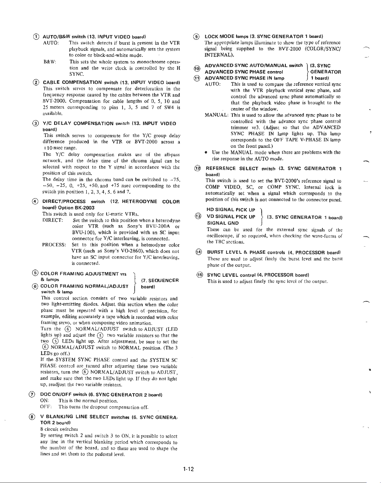
G)
AUTO/B&W
AUTO:
B&W:
switch
(13.
INPUT
VIDEO
board)
Thi
s swit ch detects if burst
is
playback signals, and automatica
to col
or
or black-and-white
This sets the whole system
mode
to monochrome
present in
ll
y sets the system
.
tion and the write clock is controlled
SYNC.
@
CABLE
COMPENSATION
switch
(13. INPUT
VIDEO
This switch serves to compensate for deterioration in the
quen
cy
respon
se
fre
BVT
-2000
. Compensation for cable lengths
25
me
ters corresponding to pins 1, 3, 5 and 7
caused by the cables between the VTR and
of
available.
@
Y/C
DELAY
board)
Thi
s switch serves
difference produced in the VTR
±
IO
nsec range.
Th
e Y
COMPENSATION
to compensate for the Y/C group del
/C
delay compen sat ion makes u
switch
(13.
INPUT
or
BVT-2000 across a
se
of the all-pass
network, and the delay time of the chroma signal can be
selected wi
positi
The
-50,
switch pin position l, 2,
©
DIRECT/PROCESS
board)
This switch
DIRECT: Set the switch
PROCESS: S
@
COLOR
& lamps
@
COLOR
switch
This
on
del
th respect
of
this switc
ay
time
to
the Y signal
h.
in
the chrom a band can be switch ed t o - 75 ,
- 25, O, +25, +50, and +
3,
4, 5, 6 and 7.
switch
Option
BK-2003
is
used only for U-matic VTRs.
col
or
VTR (such as Sony's BVU-
BVU-J
00)
connector
et
, which is provided
for Y
to this position when a hetero
VTR (such as Sony's
have an SC input conn
is
connected.
FRAMING
FRAMING
& la
mp
con
tro l secti
ADJUSTMENT
NORMALiADJUST
on
consists
in
accordance with the
75
nsec corresponding to the
(12.
HETERODYNE
to
this positi
on
when a heterodyne
with
/C
int
erleaving, is connected.
of
V0-2860)
ector
vrs
two
, which does n
for Y/C interleaving,
(7. SEQUENCER
board)
}
variable resistors and
two light-emitting diodes. Adjust this section when the col
phase must be repeated with a high level
example, edi ting accur ately a t
ape
which is recorded with color
of
precision, for
framing servo, or when composing video animation.
Turn the
li
ghts up) and adjust the
two
@ NORMAL/ADJUST
CD
LEDs lig
ht
CD
up. After adjustm
sw
itch to ADJUST (LED
two variable resistors so th
ent,
be
sure to set th e
@ NORMAL/ ADJUST switch to NORMAL position. (The 3
LEDs go
If
PHASE
resistors, turn the
and make sure that the two LEDs
up, read
Q)
DOC
ON:
Off':
@ V
TOR
8 circuit switches
By
any
the
li
off
.)
the SYSTEM SYNC PHASE co n
control
arc turn
ed
@N
ORMAL/ADJUST switch to ADJUST,
afte
r ad
tro
just
li
ght up.
just the two variable resistors.
ON/OFF
BLANKING
2 board)
setting switch 2 and switch 3
li
ne in the vertical blanki
numb
switch (6.
Thi
s is the normal pos ition.
Thi
s turns the
LINE
SYNC
GENERATOR
dropout compensa
SELECT
switches (6.
to
ng period
er
of
the board, and so these are used to shape the
nes and set them to the pedestal level.
l and the SYSTEM SC
ing these two variable
If
they
2 board)
tion off.
SYNC
ON, it
is
possible to select
which corresponds to
the
by
0, 5,
10
of
SW4
VIDEO
COLOR
200A or
an SC
dyne co
at
do not
GENERA·
VTR
opera-
the H
board)
and
ay
input
lor
ot
or
the
light
LOCK
MODE
®
Th
e appropri
lamps (3.
ate
signal being supplied to
ER
NAL).
INT
ADVANCED
ADVANCED
ADVANCED
SYNC
SYNC
SYNC
AUTO: This is used
with
co
ntr
is
that the playbac k video phase is brought to the
nt
ce
MANUAL: This is used to allow the advanced sync phase to
controll
SYNC
GENERATOR
lamps illuminate
th
e BVT-2000 (COLOR/SYNC/
AUTO/MANUAL
PHASE
control
PHASE
IN
to compare
the
VTR playba
to
show the
lamp 1 board)
the refere nce vertical sync
ck
1 board)
type of
reference
switch
} (3.
SYNC
GENERATOR
vertical sync phase, and
ol the advanced sync phase automat
er
of
the window.
ed with the advance sync phase control
ically
so
be
trimm er vr3. (Adjust so that the ADVANCED
SYNC PHASE
co
on the fro
•
Us
e the MANUAL mode when there are problems with the
se
response in the AUTO mode.
ri
REFERENCE
board)
This switch is used
COMP VIDEO, SC,
automatica
lly set wh
position of this switch is n
HD
SIGNAL
@
VD
SIGNAL
SIGNALGND
The
se
can be used for the external sy
ll
oscope, if so required, when checkin g the wave-forms
osci
rresponds
SELECT
PICK
UP }
PICK
UP (3.
IN lamp
to
the
nt
panel.)
switch (3.
to
set the BVT-2000's reference signal to
or
COM
en
a signal which corresponds to the
ot
connecte
lights up . This lamp
OFF
TAPE V-PHASE IN lamp
SYNC
GENERATOR
P SYNC. Internal lock is
d to the connect
SYNC
GENERATOR
nc
or
1 board)
signals of the
1
panel.
of
the TBC sections.
@
BURST
@
LEVEL
These are used
phase
of
the
output.
SYNC
LEVEL control
& PHASE
to
controls
(4. PROCESSOR board)
adjust finely the burst level and the burst
(4. PROCESSOR board)
This is used to adjust finely the sync level
of
the ou tput.
1-12
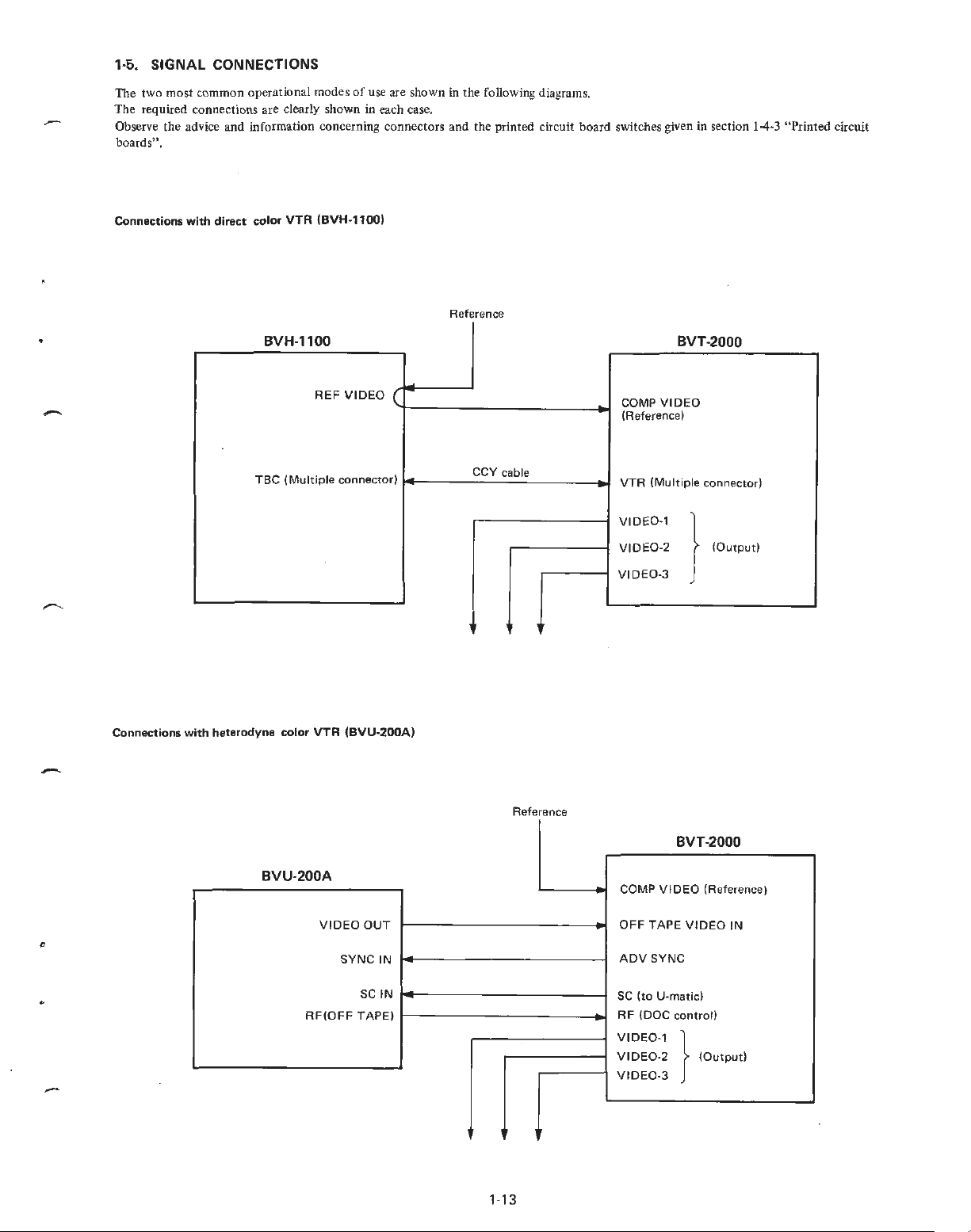
1·5. SIGNAL CONNECTIONS
The two most common operational modes
The required connections are clearly shown in each case.
Observe the advice and information concerning connectors and the printed c
boards".
Connec
tions
with
direct
color
VTR
of
use are shown in the following d iagrams.
(BVH-1100)
Reference
ir
cuit board switches given in secti
on
1-4
-3
"Printed circuit
Connections
BVH-1100
TBC
(Mult
with heterodyne color
REF
VIDEO
iple connector)
VTR
(BVU-200A)
BVT-2000
~
(
CCV cable
COMP
VIDEO
(Reference)
VTR (Multiple connector)
-
VIDE0
-1
VIDE0-2
0-3
}
V
IDE
(Output)
, ,
Reference
BVT
-2000
BVU-200A
VI
DEO
OUT
c
SY
NC IN
SC
IN
"
RF(OFF
TAPE)
-
- COMP V IDEO (Reference)
OFF
TAPE
VIDEO IN
ADV
SYNC
SC
(to
U-matic)
RF
(DOC
control)
VIDE0-
1 }
V
IDE
0-2
VIDE0-3
(Output)
.
,.
1-13

1·6.
OPTIONAL
1-6·1. Dynamic tracking memory
When
com
bining the BVT-20
tracking playba
plug o
ne
of
Whereas the correcti
board, two boards
to yie ld
Using the M
containing a great deal
recorded on a p
phase sh ift whi ch is produced with a correcti
be eliminated.
opt
BVT-2000) into slot
prop
er pictures
EM
ADAPTOR
00
ck
(guard ba
ional memory
ex
OR Y boards is effecti
ortab
nd
noise-less playba ck), it
board
numb
er 8 (16).
on
range is 4 Hp-p with o
pand th
is
with
dynam
of jitter
le U-matic while
AND
board
with the
(same as MAIN MEMORY board
range to 12 Hp-p.
ic tracking playback.
ve
when playing back a tape
(for example, a tape which has been
on
ACCESSORIES
BK-2001
BVH-1
000
for dynamic
is necessary to
ne MAIN MEMORY
It
is also po ssible
the move
on
ran
).
The vertica l
ge
of 4 Hp·p
can
1-7. BREAKERS
When
no
power is supplied to
panel as
in
the photo
If
the breaker s are
after power is supplied, inspe
nothing appears wrong, contact the Sony broadcasting service
below and inspect the two breakers.
OFF,
the
BVT-2000,
set them
to
ON but
ct
the power supply and
ope
n the conn
if
they return to OFr
the
voltage. If
ector
s.
1-6-2. Heterodyne color
Use this adapter when converting the playback signals
h
etero
dyne color VTR
connector into standard broadcasting
possib le
base corrector with microcircuits even when a VTR, which is
provided with a subcarrier input connector,
The
HETERODYNE C
mark
f or the above instances, set the DIRECT/ PROCESS switch
board
DIRECT.
to
ret
urn
adapter
is configured as a single printed circuit
ed
by slot number 12
to
PROCESS, and for a
the
OLOR), and it
VTR
color
(V0-2860)
subcarrier signal to
on
the time base correc to
ll oth
wit
signals~
is inserted
er
instances, set the swit
processor
hout
the
is
BK-2003
a subcarrier inpu t
or when it is
VTR from the time
being employed.
into the
r.
board
of
not
(called
position
on the
ch to
a
-
Two breakers
1·
•
14
 Loading...