

Page 1

COLOR VIDEO CAMERA
BVP-E30 series
OPERATION MANUAL [English]
1st Edition
Page 2

WARNING
To prevent fire or shock hazard, do not
expose the unit to rain or moisture.
To avoid electrical shock, do not open the
cabinet. Refer servicing to qualified
personnel only.
For the customers in the USA
This equipment has been tested and found to comply with the
limits for a Class A digital device, pursuant to Part 15 of the
FCC Rules. These limits are designed to provide reasonable
protection against harmful interference when the equipment
is operated in a commercial environment. This equipment
generates, uses, and can radiate radio frequency energy and,
if not installed and used in accordance with the instruction
manual, may cause harmful interference to radio
communications. Operation of this equipment in a residential
area is likely to cause harmful interference in which case the
user will be required to correct the interference at his own
expense.
You are cautioned that any changes or modifications not
expressly approved in this manual could void your authority
to operate this equipment.
Für Kunden in Europa
Dieses Produkt besitzt die CE-Kennzeichnung und erfüllt die
EMV-Richtlinie (89/336/EWG) der EG-Kommission.
Angewandte Normen:
• EN55103-1: Elektromagnetische Verträglichkeit
(Störaussendung)
• EN55103-2: Elektromagnetische Verträglichkeit
(Störfestigkeit),
für die folgenden elektromagnetischen Umgebungen: E1
(Wohnbereich), E2 (kommerzieller und in beschränktem
Maße industrieller Berei ch), E3 (St adtbereich i m Freien) u nd
E4 (kontrollierter EMV-Bereich, z.B. Fernsehstudio)
Voor de Klanten in Nederland
Gooi de batterij niet weg, maar lever hem in als
KCA.
Note on laser beams
Laser beams may damage the CCDs. If you shoot a
scene that includes a laser beam, be careful not to let
a laser beam become directed into the lens of the
camera.
The shielded interface cable recommended in this manual
must be used with this equipment in order to comply with the
limits for a digital device pursuant to Subpart B of Part 15 of
FCC Rules.
For the customers in Eur ope
This product with the CE marking complies with the EMC
Directive (89/336/EEC) issued by the Commission of the
European Community.
Compliance with this directive implies conformity to the
following European standards:
• EN55103-1: Electromagnetic Interference (Emission)
• EN55103-2: Electromagnetic Susceptibility (Immunity)
This product is intended for use in the following
Electromagnetic Environment(s):
E1 (residential), E2 (commercial and light industrial),
E3 (urban outdoors) and E4 (controlled EMC environment,
ex. TV studio).
Pour les clients européens
Ce produit portant la marque CE est conforme à la Directive
sur la compatibilité électromagnétique (EMC) (89/336/CEE)
émise par la Commission de la Communauté européenne.
La conformité à cette directive implique la conformité aux
normes européennes suivantes
EN55103-1: Interférences électromagnétiques (émission)
EN55103-2: Sensibilité électromagnétique (immunité)
Ce produit est prévu pour être utilisé dans les environnements
électromagnétiques suivants:
E1 (résidentiel), E2 (commercial et industrie légère), E3
(urbain extérieur) et E4 (environnement EMC contrôlé, ex.
studio de télévisi on) .
:
2
Page 3

Table of Contents
Using the CD-ROM Manual..................................................4
CD-ROM System Requirements ...............................................4
Preparations ...............................................................................4
Reading the CD-ROM Manual..................................................4
Overview ...............................................................................5
Features......................................................................................5
Optional Accessories ................................................................ 7
Location and Function of Parts...........................................8
Side Panels................................................................................ 8
Front Panel...............................................................................10
Setting Up the Camera.......................................................12
Attaching a Lens to the Camera...............................................12
Attaching a 1.5-type/2-type Viewfinder..................................13
Attaching the Camera Adaptor or Wireless Camera
Transmitter.....................................................................15
Adjusting the Shoulder Pad Position.......................................16
Mounting the Camera to a Tripod ...........................................17
Using a Memory Stick.................................................. .... ..18
Notes on Memory Stick...........................................................18
Display on the Viewfinder Screen.....................................20
Menu Operation.................................................. ..... ..... .... ..21
Displaying the Menu................................................................21
Displaying the TOP MENU.....................................................21
Selecting a Menu Page From the CONTENTS Screen ...........21
Setting the Menu......................................................................21
Using the USER Menu ............................................................22
MENU Items........................................................................... 25
Specifications.....................................................................33
Table of Contents
3
Page 4

Using the CD-ROM Manual
The supplied CD-R OM include s versions of the Operati on
Manual for the BVP-E30 series (Japanese, English,
French, German, Italian, and Spanish versions).
CD-ROM System Requirements
The following are required to access the supplied CDROM disc.
• Computer: PC with Intel Pentium CPU
– Installed memory: 64 MB or more
–CD-ROM drive: ×8 or faster
• Monitor: Monit or suppor ting resol uti on of 800 × 600 or
higher
• Operating system: Microsoft Windows Millennium
Edition, Windows 2000 Service Pack 2, Windows XP
Professional or Windows XP Home Edition
When these requirements are not met, access to the CDROM disc may be slow, or not possible at all.
Preparations
One of the following programs must be installed on your
computer in order to use the operation manuals contained
on the CD-ROM disc.
• Adobe Acrobat Reader Version 4.0 or higher
• Adobe Reader Version 6.0 or higher
Reading the CD-ROM Manual
To read the operation manual contained on the CD-ROM
disc, do the following:
1
Insert the CD-ROM disc in your CD-ROM drive.
A cover page appears automatically in your browser.
If it does not appear automatically in the browser,
double-click the index.htm file on the CD-ROM disc.
2
Select and click the operation manual that you want to
read.
This opens the PDF file of the operation manual.
Note
If you lose the CD-R OM di sc or become una ble to r ead its
content, for example because of a hardware failure, you
can do one of the following:
• You can purchase a new CD-ROM disc to replace one
that has been lost or damaged. Cont act your Sony service
representative.
• You can purchase printed versions of the operation
manuals. Contact your Sony service representative.
When ordering, be sure t o specify the p art number of t he
manual you want.
– 3-854-246-0x (Japanese version for NTSC models
only)
– 3-854-247-0x (English version)
– 3-854-248-0x (French version)
– 3-854-249-0x (German version)
– 3-854-250-0x (Italian version)
– 3-854-251-0x (Spanish version)
Note
If Adobe Reader is not installed, you can download it f rom
the following URL:
http://www.adobe.com/
• Intel and Pentium are registered trademarks of Intel Corporat ion
or its subsidiaries in the United States and other countries.
• Microsoft and Windows are registered trademarks of Microsoft
Corporation in the United States and/or other countries.
• Adobe, Acrobat, and Adobe Reader are trademarks of Adobe
Systems Incorporated in the United States and/or other countries.
Using the CD-ROM Manual
4
Page 5

Overview
The BVP-E30-series Color Video Camera is a digital
portable camera with functions and performance suitable
for use in a studio as well as for outside broadcast
applications. The BVP-E30 (NTSC model) and BVPE30P (PAL model) are designed only for the aspect ratio
4:3. With the BVP-E30WS (NTSC model) and BVPE30WSP (PAL model), the aspect ratio is switchable
between 4:3 and 16:9.
By using the BVP-E30-series camera with a camera
adaptor (CA), camera control unit (CCU), video selector
(VCS), master setup unit (MSU), remote control panel
(RCP), etc., a wide variety of systems from a basic to a
large system can be configured for your special purposes.
While based on Son y's long-culti vated t echnologies for the
BVP-series camera for broadcasting use, the BVP-E30series camera is a new-generation camera with advanced
performance, functions, and qualit y, achie ved b y adopting
a Mega Pixel CCD, the newly developed 8-million-gate
process LSI, and excellent circuit and mounting
technologies.
Features
Lower smear
Thanks to the Power HAD EX technol ogy , the smear le v el
has been largely impro ved by about 25 dB (compared with
the Sony IT POWER HAD CCD) to –145 dB or less.
Progressive Scan (PsF)
By adopting the double-density CCD, Progressive Scan
(PsF) is possible. Progressive Scan signals from the CCD
are converted to and output as interlaced signals by the
frame memory (Segment Frame system), thus enabling
handling of a Progressive Scan system without changing
the existing system.
Versatility, high reliability
Thanks to the newly developed 8-million-gate largeprocessing LSI using 0.18-mi cr on processing technology,
most of signal processing of camera i s handled by a single
chip, achieving a drast ic reduct ion in power consumption,
as well as variety of functions, higher picture quality, and
higher reliability.
Cross-color suppression
A high-performance cross-color-suppression circuit built
into this camera suppresses cross colors in composite
video signals without degrading the resolution. As the
circuit processes signals as RGB component signals, this
function is also effective for CCU output and digital
component output.
High quality
The newly developed Mega Pixel Power HAD EX CCD
assures higher signal-to-noise ratio, higher sensitivity,
broader dynamic range, and less smear. In addition, by
adopting the double-density C CD, Progressi v e Scan (PsF)
is also possible.
High S/N
A higher signal-to-noise rati o, –67 dB (typical) for NTSC,
and –65 dB (typic al) for PAL, has been achieved a s a result
of the newly adopted Power HAD EX CCD and excellent
circuit and mounting technologies.
High sensitivity
A sensitivity of F11 at 2,000 lux (typical) has been
achieved . When the vid eo gain is raise d by 42 d B, a video
level of 100% is obtained with minimum subject
illuminance of 0.25 lux.
Wide dynamic range
With 600% dynamic range assured, capabilities such as
knee saturation and adaptive knee enable reproducing
high-luminance subjects clearly.
Low key saturation
Coloring in dark parts, in whic h colors are difficult to
distinguish, can be controlled.
Selectable gamma curves
The gamma curve is selectable from among various
options.
Digital encoder
The digitalized encoder circuits, converged into a single
LSI chip, produce accurate and stable signal output.
2D-black-shading/3D-white-shading/dynamicshading compensation functions
High-accuracy shading compensation for both dark and
bright parts allows pictures with less shading. The
dynamic-shading function is activated only when a lens
allowing this function is attached.
Knee saturation/adaptive saturation
Greatly improved knee saturation and adaptive saturation
enable reproducing high-luminance subjects clearly and
gaining pictures with a wider dynamic range.
Electronic soft focus
Compared with the conventional detail compensation,
which could only sharpen images, the electron ic soft-focus
Overview
5
Page 6

mechanism adopted in this camera also allows you to
soften images.
Triple-skin-tone-detail control
Skin-tone detail correction that allows detail to be set
independently for each of the three separate color ranges is
provided. The combination of the skin-tone detail control
and the above-mentioned electronic soft focus results in
more effective detail compensation.
16-axis multimatrix hue control
Hue is divided into 16 blocks, and their phases and
saturations can be controlled independently. Thus, subtle
hue adjustment in cases where as hue adjustment is
required among various cameras, can be easily made.
NAM V DTL (vertical detail generation mode)
Vertical detail signals are made for R, G, and B signals
individually, and the largest signal among them is selected
as the final V-detail signal. This method, compared with
the conventional simple addition m ethod, allows you to
improve resolution with a highly saturated subject. The
conventional V-detail generation method can also be
selected, if necessary.
Electronic color-temperature conversion (5600K)
Color-temperature conversion at 5600K is electronically
conducted. Thus, instead of an optical color-temperature
conversion filter, the number of ND filters can be
increased.
Full-servo optical-filter discs
A pair of motor-operated optical-filter discs are standard
equipment with the BVP-E30/E30WS/E30WSP. This
enables you to remotely control the camera from an MSU
or RCP, facilitating system operation.
For the BVP-E30P, a single manual filter is provided.
Slow-Shutter mode
By controlling CCD reading, shooting in Slow-Shutter
mode of 7 frames at maximum is enabled.
Excellent operability
Memory Stick an d file system
In addition to the conventional reference file, scene file,
and lens file, the operator file is newly adopted. In the
operator file, data such as switch settings of the camera and
customized sets of menu selections are stored. File data are
stored in the Memory Stick, and can be quickly called
from it.
USER Menu and OPERATION Menu
The USER Menu, which allows you to place only menu
items of your choice in any order, and the OPERATION
Menu, which allows you to sel ect items to b e disp lay ed in
the viewfinder and to assign switch se ttings, are provided.
PAINT Menu and MAINTENANCE Menu
Adjustment and maintenance of the camera can be made
by menu operation.
Assignable button and Handle buttons
To the Assignable button a t the top of the side panel, any
function among 5600K, ATW, and CROP (only for the
BVP-E30WS/E30WSP) can be assigned.
To the two handle buttons lo cated on the handle of the
camera, any two functions among return video, intercom,
and zoom control of the lens (only for lenses with zoom
control function) can be assigned.
Overview
6
Page 7
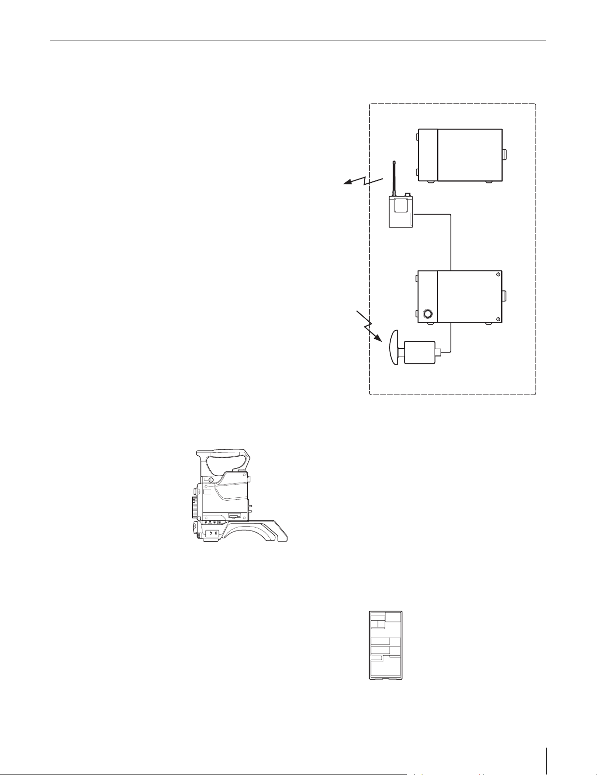
Optional Accessories
The following optional accessories are available.
Overview
7
Page 8
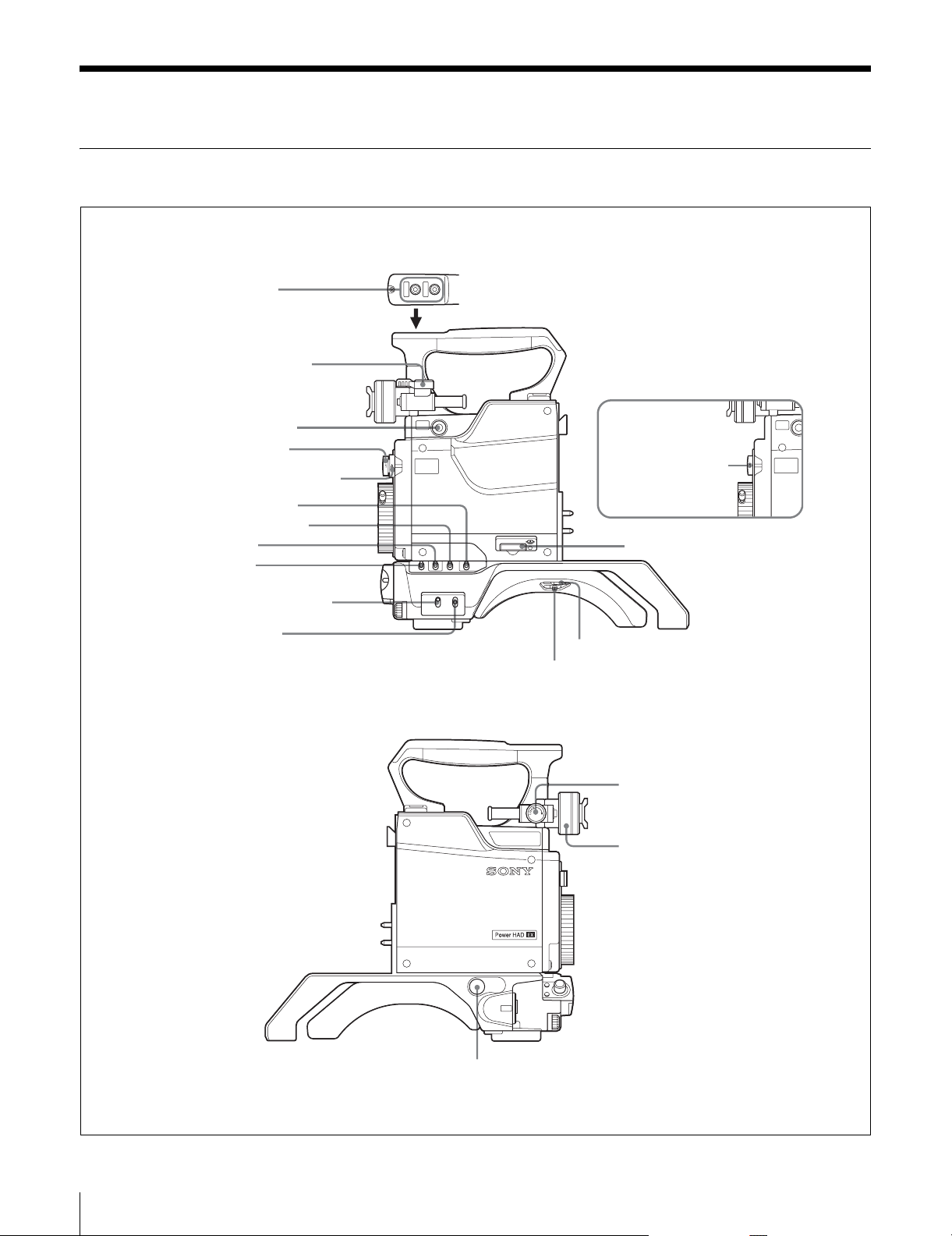
Location and Functio n of Parts
Side Panels
a Handle buttons
b Viewfinder lock lever
c Assignable button
d ND filter selector
e CC filter selector (BVP-
E30/E30WS/E30WSP only)
f WHITE BAL switch
g OUTPUT/DCC switch
h GAIN switch
i VTR switch
j STATUS/CANCEL switch
k DISPLAY switch
RET1
INCOM
BVP-E30P
d ND filter selector
l Memo ry Stick slot
MENU
GENLOCK
BAL
GAIN
WHITE
OUTPUT
ON
OFF
MENU
DISPLAY
VTR
STATUS
CANCEL
m Shoulder pad lock lever
n CA lock screw
Location and Function of Parts
8
o LOCK knob
p Viewfinder lock ring
TESTOUT
MIC
q TEST OUT connector
Page 9

a Handle buttons
The function of each of these buttons is assignable in the
menu operation.
At the factory, the front-side button is set to RET 1, and the
rear-side button is set to INCOM 1.
RET 1 (retur n video 1): A return video 1 signal from the
Camera Control Unit (CCU) is displayed on the
viewfinder screen while this button is pressed.
INCOM (intercom 1): The intercom microphone is ON
while this button is pressed.
For details, see “Menu Operation” on page 21.
b Viewfinder lock lever
Locks the viewfinder after adjusting the position in the
front-to-rear direction together with the LOCK knob.
c Assignable button
Desired function can be assigned to this button by the
menu operation.
On the BVP-E30P, a color temperature conversion f ilter of
5600K is set for the button at the factory. The setting can
be changed with the OPERATION Menu.
On the BVP-E30/ E30WS/ E30W SP, nothing is set. S et th e
function with the OPERATION Menu as required.
For details, see “Menu Operation” on page 21.
d ND filter selector
Selects the desired ND filter.
Filter No. Filter
1 Clear
21/4ND
3 1/16ND
4 1/64ND
e CC (color temperature conv ersion) filter (BVP-E30/
E30WS/E30WSP only)
Selects the desired CC filter suitable for the lighting
conditions.
Filter No. Filter
ACross filter
B 3200K (Clear)
C 4300K
D 6300K
f WHITE BAL (white balance memory select) switch
Selects the white balance adjustment me thod and memory
cell to store the adjusted value.
PRESET: White balance is automatically adjusted to the
preset value for the color temperature of 3200K.
A or B: Memory cell A or B is selected.
g OUTPUT /DCC (output signal select/auto knee)
switch
Selects an output sign al supplied to a VTR, vie wfinder , and
video monitor (color-bar sig nals or camera picture). When
a camera picture is selected, the auto kn ee function can be
activated.
BARS/OFF: Color-bar signals are output, and the auto-
knee circuit does not function.
CAM/OFF: A camera picture is output, but the a uto-knee
circuit does not function.
CAM/ON: A camera picture is output, and the auto-knee
circuit functions.
h GAIN switch
Selects the appropriate video gain according to the
illumination of the subject to be shot. The values for
positions L, M, and H, are set with the OPERATION
Menu.
For details, see “Menu Operat ion” on page 21.
i VTR switch
When a portable VTR is connected to the camera via the
CA-570/570P/950/950P Camera Adaptor, the VTR starts
recording as follows:
SAVE: Power-save position for recording. Recording
starts a few seconds after the VTR START button is
pressed. A newly recorded picture may not smoothly
be connected to the previously recorded part.
STBY (standby): Recording starts immediately upon
pressing the VTR START button.
Note
The WHITE BAL, OUTPUT/DCC, GAIN, and VTR
switches do not function when the camera is connected to
a Camera Control Unit (CCU), Remote Control Panel
(RCP) or Remote Control Unit (RM).
j STATUS/CANCEL switch
STATUS: The setting status of the camera is displayed on
the viewfinder screen when the switch is set to this
position after setting the DISPLAY switch to ON.
CANCEL: When the DISPLAY switch is in the MENU
position, set the switch to this position to cancel the
selection made by the MENU SELECT knob and
restore the previously selected menu item.
k DISPLAY switch
Used for displaying the current status of the camera,
settings of format and assignable buttons, and menu on the
viewfinder screen.
ON: Display function activated
OFF: Display function not activated
MENU: A screen for setting the displaying items and
functions a ppears.
For details, see “Menu Operat ion” on page 21.
Location and Functio n of Parts
9
Page 10
l M emory Stick slot
Insert a Memory Stick to store file data.
For details, see “Using a Memory Stick” on page 18.
m CA lock screw
Tighten the screw to secure the CA-570/570P/950/950P
Camera Adaptor or the WLL-CA55 Wireless Camera
Transmitter to the camera.
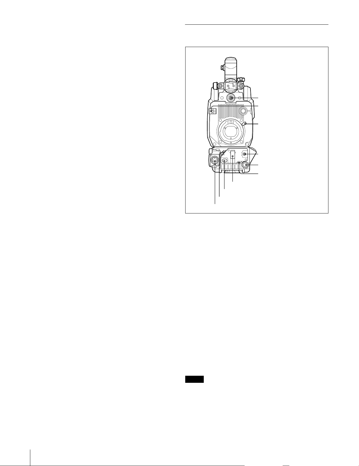
Front Panel
n Sho ulder pad lock lever
Raise up the lever to move the shoulder pad forwards or
backwards. Do this to ensure the best balance when
shooting with the camera on your shoulder.
For detail s, see “Adjusti ng th e Should er Pad Positio n” on
page 16.
o LOCK knob
Locks the viewfinder after adjusting the position in the
front-to-rear direction together with the viewfinder lock
lever.
p Viewfinder lock ring
Locks the viewfinder after adjusting the position side to
side.
q TE ST OUT connector (BNC type)
Supplies the signal selected with the menu operation o r the
remote control panel.
VF
AUTO W/B BAL
WHT
SHUTTER
OFF
LENS
ON
VTR START
h VTR START button
i LENS connector
j MIC connector
BLK
SEL
MIC
LEVEL
g SHUTTER switch
a V F connector
b Cable clamp
c Lens mount lever
d AUTO W/B BAL switch
e MENU SELECT knob
f MIC LEVEL control
a VF (viewfinder) connector (20-pin)
Connect the 20-pin v ie wfi nder cable o f the BV F-10/10CE/
20W/20WCE Viewfinder.
b Cable clamp
Secures a microphone cable and lens cable.
c Lens mount lever
Secures the lens to the lens mount.
F or de tails, see “Attac hing a Lens to the C amera” on pag e
12.
d AUTO W/B BAL (automatic white balance/black
balance adjustment) switch
Adjusts the white balance and black balance automat ically .
WHT: The white balance is aut omatically adjusted. When
the WHITE BAL switch on the side of th e camera is
set to A or B, the adjusted value is stored in memory
cell A or B.
BLK: The black balance is automatically adjusted. The
black set is simultaneously adjusted.
Notes
• The A UTO W/B B AL swi tch does not fun ction when th e
camera is connected to a CCU, RCP, or RM.
• Do not turn off the power while automatic adjustment of
white balance or black balance i s in progress. The set up
values of the camera may not be correctly stored.
Location and Function of Parts
10
Page 11

e MENU SELECT knob
When the DISPLAY switch on the side panel is set to
MENU and the menu is displayed, turn this control knob
to select a menu item and press it to register the selection.
For details, see “Menu Operation” on page 21.
pressing it again stops recording. It is the same function as
with the VTR button on the lens .
i LENS connector (12-pin)
Connect a lens cable.
f MIC LEVEL (microphone level) control
When a portable VTR is connected using the CCZ cable of
the CA-570/570P Camera Adaptor, the microphone level
can be adjusted by turning this control.
When the CA-570/570P Camera Adaptor is used and the
LEVEL/MIC switch on the rear panel of the camera
adaptor is set to FRONT/OFF, the sound volume of the
intercom can be adjusted using this control.
g SHUTT ER switch
OFF: An electronic shutter does not function.
ON: An electronic shutter is activated.
SEL: The shutter speed and shutter mode change each
time the switch is set to this po sition.
When you set the shutter mode to SLS, the camera
enters Slow-S hutter mode (Acc umulation mode). You
can select the accumulation t ime in the rang e of 1 t o 7
frames using the PAINT Menu.
Notes
• In Slow-Shutter mode, the following restrictions are
generated:
Iris: When a remote control unit is connected, AUTO
IRIS mode is set to OFF. When no remote control
unit is connected and the camera is used in AUTO
IRIS mode, the iris is forcibly opened. If you wish to
adjust the iris, set AUTO IRIS to OFF using the
MAINTENANCE Menu and adjust it manually.
Flare compensation: The FLARE setting on the SW
ST ATUS (P1) page selected from the P AINT Menu is
forcibly set to OFF.
Auto white balance: The time required for automatic
white balance adjustment may be prolonged
depending on the setting of accumulation time.
• The following phenomena are due to the characteristics
of a CCD in Slow-Shutter mode and are not defects of
the product. For details, consult your Sony service
personnel:
– White dots on the CCD become clear when you
increase the number of frames fo r Slo w- Shutter mode.
– The pict ure is distorted when the c amera is switched to
Slow-Shutter mode.
• The SHUTTER switch does not function when the
camera is connected to a CCU, RCP, or RM.
j MIC (microphone) connector (3-pin)
Connect a microphone cable.
Normally , connect the microphone su pplied with the BVF10/10CE/20W/20WC E Viewfinder .
Phantom powering is turned off with the appropriate
internal switch setting.
For setting the switch, consult your Sony service
personnel.
h VTR START button
When a Camera Control Unit (CCU) is connected, the
audio signal of the intercom is sent to the CCU while this
button is held pressed.
When a VTR is connected using the CCZ cable of the
CA-570/570P, pressing this button starts recording, and
Location and Functio n of Parts
11
Page 12

Setting Up the Camera
Attaching a Lens to the Camera
Attach an optional l ens as described below.
For details on the lens, refer to the instruction manual
furnished with the le ns.
Attaching procedure
1
Turn the lens mount lever on the front panel fully
counterclockwise and remove the mounting cap.
Lens mount lever
3
Turn the lens mount lever fully clockwise while
holding the lens to secure it.
4
Connect the lens cable to the LENS connector.
5
Secure a cable with the cable clamp.
2
Align the center pin of the lens with the recess at the
top of the lens mount section and set the lens in place.
Lens mount lever
3
2
Align the center pin with
the recess.
Setting Up the Camera
12
Page 13

Attaching a 1.5-type/2-type Viewfinder
Attach a BVF-10/10CE/20W/20WCE as described below.
For details on the viewfinder, refer to the instruction
manual of the viewfinder.
Attaching procedure
1
Slide the viewfinder in the direction of the arrow.
The viewfinder stopper automatically pops down.
Viewfinder stopper
3
Loosen the viewfi nder lock lever and LOCK knob,
slide the viewfinder to the front or back to the most
convenient position, and tighten the lever and knob.
4
Connect the viewfinder cable to the VF connector of
the camera.
2
Loosen the viewf i nd er lock ring, slide the vie wfinder
side to side to the most convenient position and
tighten the ring.
Viewfinder lock ring
5
Connect the microphone cable to the MIC connector
of the camera.
Setting Up the Camera
13
Page 14

Detaching the viewfinder
1
Turn the viewfinder lock ring to loosen it.
K
C
O
L
Detaching the eyepiece
For shooting with you r eye aw ay from the vie wf inder, you
can detach the eyepiece to get a clearer view on the entire
screen. The CRT screen and mirror can also be cleaned
more easily when the eyepiece is detached.
1
Turn the eyepi ece locking ring fully counterclockwise
until the red match mar ks on t he locking ring and the
viewfinder barrel are aligned.
2
Pull the viewfinder stopper up and slide the
viewfinder in the direction of the arrow to remove it.
3
Disconnect the viewfinder cable from the VF
connector.
4
Disconnect the microphone cable from the MIC
connector.
2
Detach the eyepiece.
Reattaching the eyepiece
1
Align the red match mark on the locking ring with the
match mark on the viewfinder.
2
Align the match mark on the eyepiece with the match
marks on the eyepiece locki ng ring and the vie wfinder
barrel, then insert the eyepiece into the viewfinder
barrel.
3
Turn the eyepiece locking ring clockwise until its
LOCK indication arro whead is aligned wit h the match
mark on the viewfinder barrel.
Setting Up the Camera
14
Page 15

Cleaning the viewfinder
To ensure a clear view while shooting, you must keep the
interior of the viewfinder clean. To clean the viewfinder,
remove the viewfinder from the camera and take care not
to scratch any of the compone nts within the viewfinder.
For details on detaching the viewfinder, see “Detaching
the viewfinder” on page 14.
To remove dust from the viewfinder screen or
surface of the mi rror inside the barrel
Use a dust blower.
To clean the lens or protective fi lter
Use a commercially available lens cleaner.
Note
Never use organic solvents such as thinner.
Disassembling the eyepiece
1342
Eyecup
Attaching the Camera Adaptor or Wireless Camera Transmitter
If you attach the CA-570/57 0P/950/950P Camera Adaptor
to the camera, a portable VTR, camera control unit or A C
adaptor can be connected to the camera.
By attaching the WLL-CA55 Wireless Camera
Transmitter, video an d a udi o sig nal s can be transmitted to
a distance.
Attaching the camera adaptor or
transmitter
1
Attach the camera adaptor or transmitter to the back
of the camera.
Hook the upper part then push the lo wer part securely
in place. Then make sure the adaptor or transmitte r is
firmly attached to the camera.
Eyecup
holder
1
Detach the eyepiece unit from the viewfinder.
F or details, see “Detaching the e yepiece” on page 14.
2
Remove the eyecup from the eyecup holder.
3
Remove the protective filter, together with the
packing ring from inside the eyecup holder.
4
Detach the protective filter from the packing ring.
Protective
filter
Packing
ring
Fog-proof filter
Depending on the temperature and humi dity, the prot ecting
filter may mists, especially if y ou brea th e near i t. You can
replace the protecting filter with an optional fog-proof
filter (Part No. 1-547-341-12) to prevent the fogging.
Attaching the fog-proof filter
Remove the protecting filter together with the packing
ring, and in their place attach the fog-proof filter.
Note
When cleaning the fog-proof filter, wipe the filter very
gently with a soft cloth to a void impair ing the anti-fogg ing
effect.
2
Tighten the CA lock screw to secure the adaptor or
transmitter.
CA lock screw
Removing the camera ad aptor or transmitter
Turn the CA lock screw counterclockwise until it idles and
then remove the adaptor or transmitter wh ile holding the
screw pushed in.
Setting Up the Camera
15
Page 16

Attaching a shoulder strap
Attach a shoulder strap as shown below.
Shoulder strap post
Clip
Adjusting the Shoulder Pad Position
You can shift the shoulder pad from its center position
(factory setting) backward by up to 10 mm (3/8 inch) or
forward by up to 25 mm (1 inch). This adjustment helps
you get the best balance for shooting with the camcorder
on your shoulder.
Pull up on the strap to
lock it.
Detaching a sh oulder strap
Adjusting procedure
1
Raise the lever in the center of the shoulder pad to
unlock the shoulder pad.
2
Slide the shoulder pad backward or forw ard until it is
in the most convenient position.
3
Bring down the lever to lock the shoulder pad in the
selected position.
Setting Up the Camera
16
Page 17

Mounting the Camera to a Tripod
Mount the camera to a tripod using a VCT-14 Tripod
Adaptor.
Caution
• Select an appropriate hole from among those at the
bottom of the tripod adaptor considering the balance of
the weight of the camera and the tripod adaptor. If an
inappropriate hole is selected, the camera may fall over.
• Check that the size of the selected hole matches that of
the screw of the tripod. If they do not match, the tripod
adaptor cannot be atta ched to the tripod securely.
Mounting procedure
1
Attach the tripod adaptor to the tripod and secure it
with the screw.
Tripod adaptor
Tripod
Removing the camera from the tripod
adaptor
Hold down the red b utton and pull the le ver in the directio n
of the arrow.
Lever
Red button
If the pin of the tripod adaptor does not
return to its original position
After removing the camera, if the pin o f the tripod adap tor
does not return to its original position, hold down the red
button and move the lever in the direction of the arrow to
return the pin to its original position. It is not possible to
mount a camera with the pin not seated.
2
Place the camera on the tripod adaptor, and slide
forward it alon g the groo v e of the tripod ada ptor until
it clicks.
Tripod adaptor
Original position
Pin
Setting Up the Camera
17
Page 18

Using a Memory Stick
When a “Memory Stick” is inserted in the ca mera, the f il e
data can be stored on the “Memory Stick,” which enables
you to share data among cameras.
Inserting a Memory Stick
Insert a “Memory Stick” with the label side up into the
“Memory Stick” slot until it clicks and the access lamp
lights in red.
Access lamp
Notes on Memory Stick
What is “Memory Stick”?
“Memory Stick” is a new compact, portable and versatile
IC (Integrated Circuit) recording medium with a data
capacity that exceeds that of a floppy disk. “Memory
Stick” is specially designed for exchanging and sharing
digital data among “Memory Stic k”-compa tible pr oducts.
Because it is removable, “Memory Stick” can also be used
for external data storage.
“Memory Stick” is available in two sizes: standard size
and compact “Memory Stick Duo” size. Once attached to
a “Memory Stick Duo” adapt er, “Memory Stick Duo” is to
the same size as standard “Memory S tick” and t hus can be
used with products compliant with standard “Memory
Stick.”
Label side
Memory Stick
Notes
• Never insert/remove a “Memory Stick” while the red
access lamp is lit or flashing.
• If ERROR appears on the viewfinder screen, wait until
ERROR disappears, then remove the “Memory Stick.”
To remove a Memory Stick
If you push the inserted “Memory Stick,” the “Memory
Stick” will pop out a little. Then pull the “Memory Stick”
out.
Precautions
• To prevent data loss, make ba ckups of data frequently. In
no event will Sony be liable for any loss of data.
• Unauthorized recording may be contrary to the
provisions of copyright law. When you use a “Memory
Stick” that has been pre-recorded, be sure that the
material has been recorded in accordance with copyright
and other applicable laws.
• The “Memory Stick” application software may be
modified or changed by Sony without prior notice.
Types of “Memory Stick”
“Memory Stick” is available in the following six types to
meet various functional requirements.
“Memory Stick”
Stores any type of data except copyright-protected data
that require MagicGate copyright protection technology.
“Memory Stick (MagicGate/High-Speed Transfer
Compatible)”
Equipped with MagicGate copyright protection
technology and allows high-speed data transfer.
This type of “Memory Stick” can be used with “Memory
Stick”-compliant, “MagicGate Memory Stick”-compliant,
and “Memory Stick PRO”-compliant products.
* Operation is not guaranteed for all of the compliant products
(Some products may not accept this type of “Memory Stick.”)
The BVP-E30-series is not compliant with high-speed data
transfer with this type of “Memory Stick.”
“MagicGate Mem or y Stick”
Equipped with MagicGate copyright protection
technology.
“Memory Stick-ROM”
Stores prerecorded, read-only data. You cannot record on
“Memory Stick-ROM” or erase the prerecorded data.
“Memory Stick (with Memory Select Function)”
Composed of multiple 128MB memory units.
The mechanical switch at the back of the “Memory Stick”
allows you to select the memory unit to be used dependi ng
on usage.
The memory units cannot be used simultaneously and
continuously.
*
Using a Memory Stick
18
Page 19

“Memory Stick PRO”
“Memory Stick” with MagicGate copyright protection
technology, exclusive for “Memory Stick PRO”compliant products.
This type of “Memory Stick” cannot be used with the
BVP-E30 series.
Available types of “Memory Stick”
You can use a “Memory Stick” with the BVP-E30 series
(8, 16, 32, 64 and 128 MB compatible).
Note
You can not use a “Memory Stick Duo” alone with the
BVP-E30 series. To use a “Memory Stick Duo” with this
camera, be sure to attach it to an optional Memory Stick
Duo Adaptor. If you insert a “Memory Sti ck Duo” without
the adaptor, it may become stu ck in the slot and impossible
to remove.
Note on data read/write speed
Data read/write speed may vary depending on the
combination of the “Memory Stick” and “Memo ry Stick ”
compliant product you use.
What is MagicGate?
MagicGate is copyright protection technology that uses
encryption technology.
• Attach the label so that it does not stick out beyond the
labeling position.
• Carry and store the “Memory Stick” in its case.
• Do not touch the connect or of the “Memory Sti ck” with
anything, including your finger or metallic objects.
• Do not strike, bend, or drop the “Memory Stick.”
• Do not disassemble or modify the “Memory Stick.”
• Do not allow the “Memory Stick” to get wet.
• Do not use or store the “Memory Stick” in a location that
is:
– Extremely hot, such as in a car parked in the sun
– Under direct sunlight
– Very humid or subject to corrosive substances
Before using a Memory Stick
Terminal
Write-protect tab
Labeling position
• You cannot record or erase data when the write-protect
tab on the “Memory Stick” is set to LOCK.
• We recommend backing up important data.
• Image data may be damaged in the following cases:
– If you remove the “Memory Stick,” or turn the power
off when the access lamp is lit or flash in g
– If you use a “Memory Stick” n ear static electricity or a
magnetic field
Notes
• Do not attach anything other than the supplied label to
the “Memory Stick” labeling position.
Using a Memory Stick
19
Page 20

Display on the Vie wfinder Screen
Menu screen
Set the DISPLAY switch to MENU, and the menu screen
will appear.
<TEST/VF OUT> 1 TOP
On the viewfinder sc reen, the current status o f the camera,
as well as menu items, can be displayed.
Status display
Set the DISPLA Y switch to ON. The current settings of the
switches on the camera and automatically adju sted values
will appear.
EX F255 Z99
CAM?
CA?
WHITE:OK
D56 00
ATW
1A W:A 0dB 1/125 ssss F-15 F5.6
S1
Status screen
On the status screen, you can see the current format,
settings of the assignable buttons, etc.
TEST OUT :cENC
TEST CHARA.: ON
TEST MARKER: OFF
VF OUT : Y
MIX VF : OFF
CHARACTER SYNC: VF
1
Set the DISPLAY switch to ON.
2
Push the STATUS/CANCEL switch to STATUS.
FORMAT :59.94I
LENS VTR S/S:RET2 SW
CAM VTR S/S:RET2 SW
WHITE B :ATW
OUTPUT DCC :AUTO KNEE
ASSIGNABLE :5600K
HANDLE SW :RET/INCOM
!GAIN :3dB
!SHUTTER :1/100
!FORMAT :29.97PsF
Display on the Viewfinder Screen
20
Page 21

Menu Operation
To make TOP MENU disappear
Turn off the camera, or while holding down the MENU
SELECT knob, set the DISPLAY switch from ON to OFF.
T o perf orm menu operat ions, fi rst disp lay the menu on the
viewfinder screen.
Displaying t h e Menu
Set the DISPLAY switch to MENU. The OPERATION or
USER menu, whichever was displayed when the camera
was turned off, will appear.
To display a desired menu page
1
Turn the MENU SELECT knob to move the arrow to
the figure on the top of the screen.
2
Push the MENU SELECT knob.
The arrow changes to the question mark.
3
Turn the MENU SELECT knob until the desired
menu page appears.
4
Push the MENU SELECT knob.
The question mark changes to the arrow, and the
selected page is displayed.
To make the menu disappear
Set the DISPLAY switch to OFF.
Selecting a Menu Page From the CONTENTS Screen
When you display the CONTENTS screen (page 0) of each
menu, the pages of the menu are listed on the display.
Turn the MENU SELECT knob to move the arrow to the
desired page, and push the MENU SELECT knob.
The selected menu page is displayed.
Setting the Menu
Display the menu page on which you wish to make
settings, then follow the procedure below.
LENS
O
FF
VTR
A
U
T
O
STA
R
O
S
T
N
E
L
SHUTTER
W
/B
B
AL
W
H
T
B
LK
M
IC
LEV
E
L
R
T
V
S
U
T
A
T
S
L
E
C
N
A
C
N
E
M
O
L
N
E
G
STATUS/CANCEL switch
MENU SELECT knob
L
E
A
T
B
IT
U
H
P
W
IN
T
A
U
G
O
N
O
F
F
O
U
N
E
M
Y
A
L
P
IS
D
U
K
C
DISPLAY switch
Displaying th e TOP MENU
You can display the TOP MENU by one of the following
methods:
• While holding down the MENU SELECT knob, set the
DISPLAY switch from OFF to ON.
• While holding down t he MENU SELECT knob, turn on
the camera.
• Select TOP at the right top on the menu.
<TOP MENU>
cUSER
USER MENU CUSTOMIZE
OPERATION
PAINT
MAINTENANCE
FILE
DIAGNOSIS
1
Turn the MENU SELECT knob to move the arrow to
the item to be selected.
2
Push the MENU SELECT knob.
The arrow changes to a question mark.
3
Turn the MENU SELECT knob to select a setting
item or value.
4
Push the MENU SELECT knob.
The question mark changes to an arrow, and the
selected item or value is set.
Repeat steps 1 through 4 as required.
5
Set the DISPLAY switch to OFF when you are
finished making settings.
Menu Operation
21
Page 22

To cancel a setting
Push the ST A TUS/CANCEL switch to CANCEL while the
question mark is displayed in step 3. The original setting
will be restored.
Using the USER Menu
Upon setting of numbers 1 through 5, <USER PAGE
1> through <USER PAGE 5> have been set . You can
change these settings as desired.
4
Turn the MENU SELECT knob to select the number
for which the menu page is to be set, then push the
MENU SELECT knob.
You can select desired pages from the OPERATION,
P AINT, MAINTENANCE, FILE, and DIAGNOSIS menu
pages, and copy and set them on the USER Menu. If you
set pages frequently used on the USER Menu, you can
easily call the pages and use them.
On the USER Menu, USER PAGE 1 through USER P A GE
5 are provided. You can place up to ten desired menu items
on each of these pages.
Setting desired menu pages on the USER
Menu
1
Display the TOP MENU screen.
For details on displ aying th e TOP MENU screen, see
“Displaying the TOP MENU” on page 21.
2
Turn the MENU SELECT knob to select USER
MENU CUSTOMIZE, then push the MENU
SELECT knob.
The CONTENTS screen appears.
<CONTENTS> cE00 TOP
1:<PAGE EDIT>
2:<USER P1 EDIT>
3:<USER P2 EDIT>
4:<USER P3 EDIT>
5:<USER P4 EDIT>
6:<USER P5 EDIT>
7:<COSTOMIZE RESET>
The operation select screen appears.
cOVERWRITE
INSERT
MOVE
DELETE
BLANK
RET
5
Turn the MENU SELECT knob to select
OVERWRITE or INSERT, and push the MENU
SELECT knob.
The PAGE SELECT screen appears.
<PAGE SELECT> ESC
xx
c1:<TEST/VF OUT>
2:<CURSOR>
3:<ZEBRA/VF DTL>
4:<MARKER>
5:<VF DISPLAY>
6:<'!' IND1>
7:<'!' IND2>
8:<SWITCH ASSIGN1>
9:<SWITCH ASSIGN2>
10:<PRESET WHITE>
6
Turn the MENU SELE CT knob to select a menu page
to be set, then push the MENU SELECT knob.
22
3
Turn the MENU SELECT knob to select 1: <PAGE
EDIT>, then push the MENU SELECT knob.
The PAGE EDIT screen appears.
<PAGE EDIT> U1 TOP
c1:<USER PAGE 1>
2:<USER PAGE 2>
3:<USER PAGE 3>
4:<USER PAGE 4>
5:<USER PAGE 5>
6:---- 7:---- 8:---- 9:-----
Menu Operation
The selected menu page is set on the USER Menu,
and the screen returns to the TOP MENU screen.
To change th e order of the pages
1
Select USER MENU CUSTOMIZE on the TOP
MENU screen.
2
Select 1: <PAGE EDIT> on the <CONTENTS>
screen to display the PAGE EDIT screen.
3
Turn the MENU SELECT knob to select the menu
page to be moved, then push the MENU SELECT
knob.
The operation select screen appears
Page 23

4
Turn the MENU SELEC T knob to select MO VE, then
push the MENU SELECT knob.
6
Turn the MENU SELECT knob to select any of U2
through U6, then push the MENU SELECT knob.
The PAGE EDIT screen is restored.
5
Turn the MENU SELECT knob to move the arrow to
the position where the selected page is to be moved,
then push the MENU SELECT knob.
The selected page moves to the position pointed by
the arrow.
To delete a page
1
Select USER MENU CUSTOMIZE on the TOP
MENU screen.
2
Select 1: <PAGE EDIT> on the <CONTENTS>
screen to display the PAGE EDIT screen.
3
Turn the MENU SELECT knob to select the menu
page to be deleted, then push the MENU SELECT
knob.
The operation select screen appears.
4
Turn th e MENU SELE CT knob to se lect DELE TE or
BLANK, then push the MENU SELECT knob.
The selected menu page is deleted, and the PAGE
EDIT screen is restored.
Setting desired items on a USER PAGE
To set desired items on a USER PAGE, follow the
procedure below.
1
Set <USER PAGE 1> through <USER PAGE 5>.
For setting <USER PAGE 1> through <USE R PAGE
5>, see “Se tting desired menu page s on the USER
Menu” on page 22.
2
Display the TOP MENU screen.
A USER PAGE setting screen appears.
U2: USER PAGE 1 setting screen <USER P1 EDIT>
U3: USER PAGE 2 setting screen <USER P2 EDIT>
U4: USER PAGE 3 setting screen <USER P3 EDIT>
U5: USER PAGE 4 setting screen <USER P4 EDIT>
U6: USER PAGE 5 setting screen <USER P5 EDIT>
<USER P1 EDIT> U2 TOP
-----
-----
-----
-----
-----
-----
-----
-----
-----
-----
7
Turn the MENU SELECT knob to move the arrow to
the first line, then push the MENU SELECT knob.
The operation select screen appears.
8
Turn the MENU SELECT knob to select
OVERWRITE or INSERT, and push the MENU
SELECT knob.
The ITEM SELECT screen appears.
<ITEM SELECT> ESC
xx
c1:<TEST/VF OUT>
2:<CURSOR>
3:<ZEBRA/VF DTL>
4:<MARKER>
5:<VF DISPLAY>
6:<'!' IND1>
7:<'!' IND2>
8:<SWITCH ASSIGN1>
9:<SWITCH ASSIGN2>
10:<PRESET WHITE>
For details on displ aying th e TOP MENU screen, see
“Displaying the TOP MENU” on page 21.
3
Turn the MENU SELECT knob to select USER
MENU CUSTOMIZE, then push the MENU
SELECT knob.
4
Select 1: <PAGE EDIT> on the <CONTENTS>
screen to display the PAGE EDIT screen.
5
Turn the MENU SELECT knob to move the arrow to
U1 at the top of the screen, then push the MENU
SELECT knob.
The arrow changes to a question mark.
9
Turn th e MENU SELECT knob to select the page that
contains the item to be set, then push the MENU
SELECT knob.
The selected page is displayed.
10
Turn the MENU SELECT knob to select an item to be
set, then push the MENU SELECT knob.
The USER P1 EDIT screen is restored, and the
selected item is displayed.
Repeat steps 7 to 10 as required.
Menu Operation
23
Page 24

11
When setting of all items on the page is completed,
turn the MENU SELECT knob to move the arrow to
TOP at the top of the screen, then push the MENU
SELECT knob.
The TOP MENU screen is restored.
4
Turn the MENU SELECT knob to select
CUSTOMIZE RESET, then push the MENU
SELECT knob.
The message “CUSTOMIZE RESET OK?” is
displayed.
To change the order of the items
You can ch ange the o rder of the items by the same method
as that for the menu pages.
To delete an item
You can delete an item by the same method as that for the
menu pages.
Displaying the USER Menu
1
Display the TOP MENU screen.
For details on displ aying th e TOP MENU screen, see
“Displaying the TOP MENU” on page 21.
2
Turn the MENU SELECT kno b to sele ct USER, th en
push the MENU SELECT knob.
The menu page set for set ting number 1 on the PAGE
EDIT screen appears.
To display other pages
1
Turn the MENU SELECT knob to move the arrow to
the figure at the top of the screen, then push the
MENU SELECT knob.
5
Push the MENU SELECT knob.
The USER menu settings are reset.
The arrow changes to a question mark.
2
Turn the MENU SELECT knob until the desired
menu page appears, then push the MENU SELECT
knob.
The selected page is displayed.
Resetting the USER Menu settings
1
Display the TOP MENU screen.
2
Turn the MENU SELECT knob to select USER
MENU CUSTOMIZE, then push the MENU
SELECT knob.
The CONTENTS screen appears.
3
Turn the MENU SELECT knob to select 7:
<CUSTOMIZE RESET>, then push the MENU
SELECT knob.
The CUSTOMIZE RESET screen appears.
24
Menu Operation
Page 25

MENU Items
The names of menu items are listed on page 0
<CONTENTS> of each menu.
OPERATION Menu
Menu Page Items: default setting
<TEST/VF OUT> 1 TEST OUT : ENC ENC/Y/R/G/B/RETURN/VF
TEST CHARA : ON ON/OFF
TEST MARKER : OFF ON/OFF
VF OUT : Y Y/R/G/B/COLOR
MIX VF : OFF ON/OFF
CHARACTER SYNC : VF VF/TEST
<CURSOR> 2 CURSOR : OFF ON/OFF
H POSITION : 50 0 to 99
W POSITION : 50 0 to 99
H WIDTH : 50 0 to 99
V HEIGHT : 50 0 to 99
<ZEBRA/VF DET AIL> 3 ZEBRA : ON
ZEBRA1 LEVEL
WIDTH
ZEBRA2 LEVEL : 100% 50 to 109%
VF DTL : ON ON/OFF
VF DTL GAIN : 25 0 to 99
<MARKER> 4 SAFETY ZONE : OFF
ASPECTIND : OFF
CENTER MARKER : ON ON/OFF
H POSITION : 0 –99 to +99
V POSITION : 0 –99 to +99
<VF DISPLAY> 5 EX : ON 3S/ON/OFF
ZOOM : OFF 3S/ON/O F F
DISP : LEFT LEFT/RIGT (only for the lenses with this
FOCUS : ON 3S/ON/OFF (only for the lenses with this
ND : ON 3S/ON/OFF
CC : ON ON/OFF (BVP-E30WS/E30WSP only)
IRIS : ON ON/OFF
WHITE : ON 3S/ON/OFF
5600K : ON 3S/ON/OFF
GAIN : ON 3S/ON/OFF
SHUTT : ON 3S/ON/OFF
RETURN : ON 3S/ON/OFF
ATW : ON 3S/ON/OFF
: 1&2
: 75%
: 10%
: 90%
: NORMAL
: 4:3
Setting values
ON/OFF
1/2/1&2
50 to 109%
0 to 30%
ON/OFF
80/90/100/80+100/90+100
NORMAL/ASPECT
LINE/MASK/LINE&MASK/OFF
15:9 /14:9/13:9/4:3/– –
(BVP-E30WS/E30WSP only)
function)
function)
Menu Operation
25
Page 26

<VF DISPLAY>
(Continued)
< ‘ ! ’ IND1> 6
< ‘ ! ’ IND2> 7 x0.8/4:3 : ON ON/OFF
<SWITCH ASSIGN1> 8 GAIN [L] : 0dB –3/0/3/6/9/12/18/24/30/36/42
<SWITCH ASSIGN2> 9 LENS VTR S/S : RET2 SW RET2 SW/INCOM1/INCOM2
<PRESET WHITE> 10 COLOR TEMP : 3200K 2000K to 10000K
<OPERATOR FILE> 11 MEMORY STICK
5 SCENE : ON 3S/ON/OFF
AUDI O : OFF ON/OFF
TAPE : OFF 3S/ON/OFF
INCOM : ON ON/OFF
C. TEMP : OFF 3S/ON/OFF
MESSAG : ALL ALL/WRN/AT/OFF
[IND] [NORMAL]
ND
CC : ON – B – – ON/OFF ABCD
WHITE : ON – A B ON/OFF PAB
5600K : ON OFF ON/OFF ON/OFF
GAIN : ON – – L ON/OFF HLM
SHUTTER : ON OFF ON/OFF ON/OFF
EXTENDER : ON OFF ON/OFF ON/OFF
FORMAT : ON 59.94I (NTSC)/
16:9/4:3 : ON 16:9 ON/OFF 16:9/4:3
[M] : 9dB –3/0/3/6/9/12/18/24/30/36/42
[H] : 18dB –3/0/3/6/9/12/18/24/30/36/42
WHITE [B] : B B/ATW
OUTPUT [DCC] : AUTO KNEE AUTO KNEE/ADAPTIVE
RE.ROTATION : STD STD/RVS
CAM VTR S/S : RET2 SW RET2 SW/INCOM1/INCOM2
ASSIGNABLE : 5600K (BVP-E30P)
DIMMER : – – 0 to 9/– –
HANDLE SWITCH : RET-INCOM1 RET-INCOM1/RET-INCOM2/RET-PROD/
ZOOM SPEED : – – 00 to 99/– –
FINE : 0 –99 to +99
R GAIN : 0 –99 to +99
B GAIN : 0 –99 to +99
READ (MS→CAM) Reading from a “Memory Stick”
WRITE (CAM→MS) Writing to a “Memory Stick”
PRESET Restoring the preset data
FILE ID Comment for the operation file stored in a
CAM CODE : BVP-E30
DA TE
TIME
: ON 1 – – – ON/OFF 1234
ON/OFF 59.94I/29.97PsF, 50I/25PsF
50I (PAL)
5600K/ATW/CROP/– –
: – – (BVP-E30/E30WS/
E30WSP)
RET-ENG/ZOOM/– –
“Memory Stick”
26
Menu Operation
Page 27

<LENS FILE> 12 F ILE : 1 1 to 16
HA14×8
F2.0
PAINT Menu
Menu Page Items: default setting Setting values
<SW STATUS> P1 FLARE : ON ON/OFF
GAMMA : ON ON/OFF
BLK GAM : OFF ON/OFF
KNEE : ON ON/OFF
WHT CLIP : ON ON/OFF
DETAIL : ON ON/OFF
LEVEL DEP : ON ON/OFF
SKIN DETAIL : OFF ON/OFF
MATRIX : ON ON/OFF
<VIDEO LEVEL> P2
WHITE
BLACK : 0000 –99 to +99
FLARE : 0000 –99 to +99
GAMMA : 0 0 0 0 –99 to +99
V MOD : 0000 –99 to +99
FLARE : ON ON/OFF
V MOD : ON ON/OFF
TEST OUT : ENC ENC/Y/R/G/B/VF/RETURN
<GAMMA> P3
LEVEL
COARSE : 0.45 0.35 to 0.90 (0.05 unit)
GAMMA TYPE : 1 or 2 1 to 7
GAMMA : ON ON/OFF
TEST OUT : ENC ENC/Y/R/G/B/VF/RETURN
<BLACK GAMMA> P4
LEVEL
RANGE : HIGH
TEST OUT : ENC ENC/Y/R/G/B/VF/RETURN
<LOW KEY SAT> P5 LEVEL : 0 –99 to +99
RANGE : HIGH
TEST OUT : ENC ENC/Y/R/G/B/VF/RETURN
[R] [G] [B] [M]
: 0 0 0 0 –99 to +99
[R] [G] [B] [M]
: 0 0 0 0 –99 to +99
[R] [G] [B] [M]
: 0 0 0 0 –99 to +99
: OFF
: OFF
LOW/MID L/MID H/HIGH
ON/OFF
LOW/MID L/MID H/HIGH
ON/OFF
Menu Operation
27
Page 28

<KNEE> P6
K POINT
K SLOPE : 0 0 0 0 –99 to +99
KNEE : ON ON/OFF
KNEE MAX : OFF ON/OFF
KNEE SAT : 0 OFF –99 to +99 ON/OFF
AUTO KNEE : OFF OFF/AUTO/ADAPTIVE
POINT LIMIT : 0 –99 to +99
SLOPE : 0 –99 to +99
<WHITE CLIP> P7
W–CLIP
<DETAIL 1> P8 DETAIL : ON ON/OFF
LEVEL : 0 –99 to +99
LIMITER [M]
[WHT]
[BLK]
CRISP : 0 –99 to +99
LVL DEP : 0 ON –99 to +99 ON/OFF
<DETAIL 2> P9 H/V RATIO : 0 –99 to +99
FREQ : 0 –99 to +99
MIX RATIO : 0 –99 to +99
FINE DTL : 0 OFF 0 to +99 ON/OFF
KNEE APT : 0 OFF –99 to +99 ON/OFF
DTL COMB : –50 –99 to 0
<SKIN DETAIL> P10 SKIN DTL : OFF ON/OFF
SKIN GATE : OFF OFF/1/2/3
CH SW
HUE :
PHASE : 0 0 0 0 to 359
WIDTH : 29 29 29 0 to 90
SAT : –89 –89 –89 –99 to +99
LEVEL : 0 0 0 –99 to +99
<USER MATRIX> P11
R:
G: : 0 – 0 –99 to +99
B: : 0 0 – –99 to +99
MATRIX : ON ON/OFF
PRESET : – ON/OFF
USER MATRIX : – ON/OFF
[R] [G] [B] [M]
: 0 0 0 0 –99 to +99
[R] [G] [B] [M]
: 0000
: ON
: 0
: 0
: 0
[1] [2] [3]
: (ON) OFF OFF ON/OFF
AUTO AUTO AUTO
[-R] [-G] [-B]
: – 0 0 –99 to +99
–99 to +99
ON/OFF
–99 to +99
–99 to +99
–99 to +99
Executing Auto Hue
28
Menu Operation
Page 29

<MULTI MATRIX> P12 PHASE : 0 0/23/45/68/90/113/135/158/180
/203/225/248/270/293/315/338
HUE : 0 –99 to +99
SAT : 0 –99 to +99
ALL CLEAR Clearing the values for PHASE, HUE, and
SAT
MATRIX : ON ON/OFF
PRESET : ON ON/OFF
MULTI MATRIX : OFF ON/OFF
<CROSS COLOR> P13 SUPPRESSION : 0
: OFF
<SATURATION> P14 LEVEL : 0
: OFF
<SHUTTER> P15 SHUTTER : OFF
: 1/100
ECS FREQ : 30.0Hz
a)
b)
0 to 99
ON/OFF
–99 to +99
ON/OFF
OFF/ON/ECS
SLS : 1 FRAME 1 FRAME to 7 FRAME
EVS : OFF ON/OFF/–
<SCENE FILE> P16 1 2 3 4 5 STORE 1 to 5/–
STANDARD
MEMORY STIC K
READ (MS→CAM)
WRITE (CAM→MS)
FILE ID:
CAM CODE
DA TE
a) NTSC: 1/10 0, 1/125, 1/250, 1/500, 1/1000, 1/ 2000
PAL: 1/60, 1/125, 1/250, 1/500, 1/1000, 1/2000
NTSC/sF: 1/60, 1/120, 1/125, 1/250, 1/500, 1/1000
P AL/sF: 1/50, 1/100, 1/125, 1/250, 1/500, 1/1000
b)NTSC: 60.1 to 6000 Hz
PAL: 50.2 to 6000 Hz
NTSC/sF: 30.00 to 6000 Hz
PAL/sF: 25.00 to 6000 Hz
Menu Operation
29
Page 30

MAINTENANCE Menu
Menu Page Items: default setting Setting values
<AUTO SETUP> M1 AUTO BLACK
AUTO WHITE
AUTO LEVEL
AUTO WHITE SHADING
AUTO BLACK SHADING
TEST SIGNAL : OFF OFF/TEST1/TEST2
<GENLOCK>
(effective in the
standalone operation
only)
<FORMAT> M3 FORMAT : 59.94I NTSC: 59.94I/29.97PsF, PAL: 50I/25PsF
<AUTO IRIS> M4 WINDOW : 1 1/2/3/4/5/6
<WHITE SHADING> M5
<BLACK SHADING> M6
<ENCODER> M7 CHU COLOR BARS : OFF ON/OFF
M2 H PHASE [COARSE] : 0 –99 to +99
[FINE] : 0 –99 to +99
SC PHASE : 0 –99 to +99
GENLOCK : ENABLE ENABLE/DISABLE
VF VIDEO : NORMAL NORMAL/GENLOCK
PsF-SHUTTER LINK : OFF ON/OFF
CROP : OFF (16:9) OFF (16:9)/ON (4:3) (BVP-E30WS/
OVERRIDE : 0 –99 to +99
IRIS LEVEL : 0 –99 to +99
APL RATIO : 80 –99 to +99
IRIS GAIN : 0 –99 to +99
AUTO IRIS : ON ON/OFF
V SAW
V PARA : 0 0 0 0 –99 to +99
H SAW : 0000 –99 to +99
H PARA : 0 0 0 0 –99 to +99
WHITE : 0 0 0 0 –99 to +99
AUTO WHITE SHADING
WHITE SHAD MODE : RGB RGB/RB
3D WHITE SHAD : ON ON/OFF
V SAW
V PARA : 0 0 0 0 –99 to +99
H SAW : 0000 –99 to +99
H PARA : 0 0 0 0 –99 to +99
BLK SET : 0 0 0 0 –99 to +99
BLACK : 0000 –99 to +99
MASTER GAIN : 0dB –3/0/3/6/9/12/18/24/30/36/42
AUTO BLACK SHADING
2D BLACK SHAD : ON ON/OFF
CB MODE : SMPTE (NTSC)/
Q-FILTER : WIDE NORMAL/WIDE (NTSC only)
[R] [G] [B] [M]
: 0 0 0 0 –99 to +99
[R] [G] [B] [M]
: 0 0 0 0 –99 to +99
FULL(75%) (PAL)
E30WSP only)
SMPTE/EIA/FULL(75%)/FULL(100%)
(NTSC;SMPTE/PAL;FULL(75%) standard)
30
Menu Operation
Page 31

<DATE/TIME> M8 2000/04/30 08:32 day, time
DATE TYPE : 1 Y/Mn/D 1 to 6
<OHB MATRIX> M9
R
G : 0 – 0 –99 to +99
B : 0 0 – –99 to +99
PHASE : 0 0/23/45/68/90/113/135/158/180
HUE : 0 –99 to +99
SAT : 0 –99 to +99
OHB MATRIX : OFF ON/OFF
<OTHERS> M10 V DTL CREATION : NAM NAM/Y/G/R+G
DTL H/V MODE : H/V H/V V
TEST2 MODE : 3 STEP 3 STEP/10 STEP
WHITE SETUP MODE : A. LVL A. LVL/AWB
V BLANKING : 20H 19H/20H/21H (NTSC only)
FLT WHT MEM : ON ON/OFF
WHITE GAMMA RGB : OFF ON/OFF
F. No. DISP : CONTROL CONTROL/RETURN
MENU RESUME : OPE & USER OPE&USER/ALL/OFF
<INITIAL SET> M11 DESTINATION : UC UC/J
ALL PRESET
STORE FILE
[-R] [-G] [-B]
: – 0 0 –99 to +99
/203/225/248/270/293/315/338
FILE Menu
Menu Page Items: default setting Setting values
<OPERATOR FILE> F1 READ (MStCAM)
WRITE (CAMtMS)
PRESET
STORE PRESET FILE
FILE ID
CAM CODE
DA TE
<SCENE FILE> F2 1 2 3 4 5 STORE
STANDARD
MEMORY STIC K
READ (MStCAM)
WRITE (CAMtMS)
FILE ID
CAM CODE
DA TE
Menu Operation
31
Page 32

<REFER ENCE> F3 STORE FILE
STANDARD
ALL PRESET
READ (MStCAM)
WRITE (CAMtMS)
FILE ID
CAM CODE
DA TE
<LENS FILE> F4 STORE FILE
No.
NAME
F NO
SELECT CURRENT
LENS
<OHB FILE> F5 STORE FILE
<FILE CLEAR> F6 PRESET OPERATOR
REFERENCE (ALL)
10 SEC CLEAR : OFF
LENS (CURRENT)
OHB BLACK SET
OHB WHITE SHADE
OHB BLACK SHADE
OHB ND OFFSET
OHB MATRIX
MS FORMAT
: 1
DIAGNOSIS Menu
Menu Page Items: default setting Setting values
<DIAGNOSIS> D1 ROM : – –
CAMERA : – –
OHB : – –
VA : – –
DPR : – –
IF : – –
AT : – –
HUR : 0H
RM : NC
CA-570 : – –
MD : – –
AU : – –
TR : – –
Note
If NG appears, consult your Sony service personnel.
32
Menu Operation
Page 33

Specifications
Pick-up device
Pick-up device 2/3-type, interline transfer CCD
Device confi gurat io n
RGB 3-CCD system
Picture elements BVP-E30/E30WS: 980 (h) × 988 (v)
BVP-E30P/E30WSP:
980 (h) × 1164 (v)
Optical specif ications
Spectral system F1.4 prism system
Built-in filters ND filters
1: Clear
2: 1/4 ND
3: 1/16 ND
4: 1/64 ND
Color temperature conversion filters
(BVP-E30/E30WS /E30WSP only)
A: Cross filter
B: 3200K (Clear)
C: 4300K
D: 6300K
General
Power requirements
12 V DC (10.7 to 17 V DC)
Power consumption
13 W
Operating temperature
–20°C to +45°C (–4°F to +113°F)
Storage temperature
–20°C to +60°C (–4°F to +140°F)
Mass Approx. 2.4 kg (5 lb 5 oz) (not including
viewfinder)
Dimensions
Electrical characteristics
Sensitivity 2,000 lux (F11, typical)
Reflection ratio of 89.9%
Minimum subjec t illumination
About 0.25 lux (F1.4, +42 dB gain)
Video signal-to-noise ratio
BVP-E30/E30WS: –67 dB (typical)
BVP-E30P/E30WSP: –65 dB (typical)
Modulation BVP-E30/E30P:
80% (typical) at 5 MHz
BVP-E30WS/E30WSP:
80% (typic al) at 5 MHz (16:9)
60% (typical) at 5 MHz (4:3)
Smear –145 dB (typical)
Dynamic range 600%
Input connect ors
MIC XLR 3-pin, female (1)
–60 dBu (adjustable to –20 dBu with the
CCU), balanced
Output connectors
TEST OUT BNC-type (1)
1.0 Vp-p, 75-ohm terminated
VF 20-pin (1)
Input/output connectors
LENS 12-pin (1)
CA 68-pin (2)
Supplied accessories
Operation Manual (English version) (1) (Japanese v ersion
is provided only for NTSC models.)
CD-ROM Operation Manual (1)
Label for assignable button and handle buttons (1 set)
Optional accessories
For BVP-E30/E30WS
BVF-10 1.5-type Black-and-White Viewfinder
BVF-20W 2-type Black-and-White Viewfinder
BVF-55 5-type Black-and-White Viewfinder
CA-570/950 Camera Adaptor
For BVP-E30P/E30WSP
BVF-10CE 1.5-type Black-and-White Viewfinder
BVF-20WCE 2-type Black-and-White Viewfinder
BVF-55CE 5-type Black-and-White Viewfinder
CA-570P/950P Camera Adaptor
Specifications
33
Page 34

Common to BVP-E30/E30P/E30WS/E30WSP
WLL-CA55 Wireless Camera Transmitter
CAC-12 Microphone Holder
VCT-14 Tri pod Adaptor
VFH-550 5-inch Viewfinder Sports Hood
Memory Stick
Recommended equipment
WLL-RX55 Wireless Camera Receiver Unit
CCU-550D/550DP/700A/700AP/ 900 /900P Camera
Control Unit
MSU-700A/750 Master Setup Unit
RCP-700/750-series Remote Control Panel
RM-B150/B750 Remote Control Unit
VCS-700 Video Selector
CNU-500/700 Camera Command Network Unit
Design and specifications are subject to change without
notice.
BVF-10/10CE/20W/20WCE Viewfinder
(Optional)
Power requirements
9.3 V DC
Power consumption
BVF-10/10CE: 1.6 W
BVF-20W/20WCE: 2.3 W
Operating temper ature
–20°C to +45°C (–4°F to +113°F)
Storage temperature
–20°C to +60°C (–4°F to +140°F)
Dimensions (w/h/d)
BVF-10/10CE:
229 × 76 × 215 mm
1
(9
/8 × 3 × 8 1/2 inches)
BVF-20W/20WCE:
239 × 76 × 215 mm
1
(9
/2 × 3 × 8 1/2 inches)
Mass BVF-10/10CE: 530 g (1 lb 3 oz)
BVF-20W/20WCE: 580 g (1 lb 4 oz)
CRT BVF-10/10CE: 1.5-type monochrome
BVF-20W/20WCE: 2-ty pe
monochrome
Horizontal resolution
600 TV lines (at center)
Indicators REC/TALLY, BATT, VTR SAVE, !
Accessories supplied
Microphone (1)
Accessories not supplied
BKW-401 Viewfinder Rotation Bracket
Fog-proof filter (Part No. 1-547-341-12)
Lens assembly (farsighted) (–2.8 D to +2.0 D)
(Part No. A-8262-537-A)
Lens assembly (low magnification) (–3.6 D to –0.8 D)
(Part No. A-8262-538-A)
Lens assembly (standard magnification with special
compensation for aberrations)
(–3.6 D to +0.4 D)
(Part No. A-8267-737-A)
Lens assembly (high-perfo rm ance triple magnification)
(–2.42 D to +0.5 D)
(Part No. A-8314-798-A)
Lens assembly (compensation for distortion)
(–3.5 D to +0.4 D)
(Part No. A-8328-756-A)
Cushioned eyecup
• Pad (Part No. X-3678-187-1)
• Attachment (Part No. 3-682-494-02)
Design and specifications are subject to change without
notice.
34
Specifications
Page 35

The material contained in this manual consists of information
that is the property of Sony C orpora tion and is intende d so lely
for use by the purchasers of the equipment described in this
manual.
Sony Corporation expressly prohibits the duplication of any
portion of this man ual o r the use there of for any purpo se o ther
than the operation or maintena nce of the e quipment d escribed
in this manual without the express written permission of Sony
Corporation.
Page 36

BVP-E30 series (UC/CE)
Sony Corporation
B & P Company
(1)
Printed in Belgium
2004.05.08
© 2004
 Loading...