

Page 1
Professional
4-566-075-13(1)
Video Monitor
Operating Instructions
Before operating the unit, please read this manual thoroughly
and retain it for future reference.
BVM-X300
Software Version 1.0
© 2015 Sony Corporation
Page 2
Owner’s Record
The model and serial numbers are located at the rear.
Record these numbers in the spaces provided below.
Refer to these numbers whenever you call upon your
Sony dealer regarding this product.
Model No.
Serial No.
Important Safety Instructions
Read these instructions.
Keep these instructions.
Heed all warnings.
Follow all instructions.
Do not use this apparatus near water.
Clean only with dry cloth.
Do not block any ventilation openings.
Install in accordance with the manufacturer’s
instructions.
Do not install near any heat sources such as radiators,
heat registers, stoves, or other apparatus (including
amplifiers) that produce heat.
Do not defeat the safety purpose of the polarized or
grounding-type plug. A polarized plug has two blades
with one wider than the other. A grounding-type plug
has two blades and a third grounding prong. The wide
blade or the third prong are provided for your safety.
If the provided plug does not fit into your outlet,
consult an electrician for replacement of the obsolete
outlet.
Protect the power cord from being walked on or
pinched particularly at plugs, convenience receptacles,
and the point where they exit from the apparatus.
Only use attachments/accessories specified by the
manufacturer.
Use only with the cart, stand, tripod,
bracket, or table specified by the
manufacturer, or sold with the apparatus.
When a cart is used, use caution when
moving the cart/apparatus combination to avoid
injury from tip-over.
Unplug this apparatus during lightning storms or
when unused for long periods of time.
Refer all servicing to qualified service personnel.
Servicing is required when the apparatus has been
damaged in any way, such as power-supply cord or
plug is damaged, liquid has been spilled or objects
have fallen into the apparatus, the apparatus has been
exposed to rain or moisture, does not operate
normally, or has been dropped.
WARNING
To reduce the risk of fire or electric shock, do not
expose this apparatus to rain or moisture.
To avoid electrical shock, do not open the cabinet.
Refer servicing to qualified personnel only.
THIS APPARATUS MUST BE EARTHED.
WAR NIN G
When installing the unit, incorporate a readily accessible
disconnect device in the fixed wiring, or connect the
power plug to an easily accessible socket-outlet near the
unit. If a fault should occur during operation of the unit,
operate the disconnect device to switch the power supply
off, or disconnect the power plug.
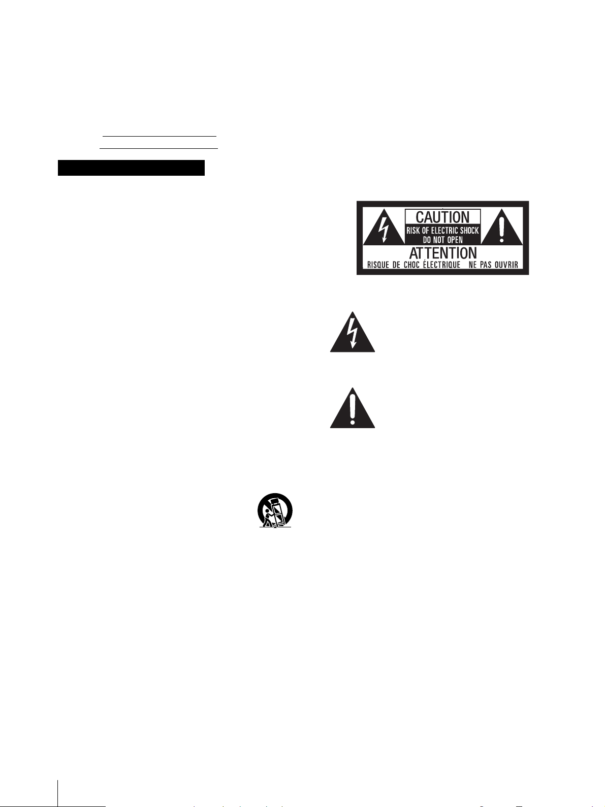
This symbol is intended to alert the user
to the presence of uninsulated “dangerous
voltage” within the product’s enclosure
that may be of sufficient magnitude to
constitute a risk of electric shock to
persons.
This symbol is intended to alert the user
to the presence of important operating
and maintenance (servicing) instructions
in the literature accompanying the
appliance.
CAUTION
The apparatus shall not be exposed to dripping or
splashing. No objects filled with liquids, such as vases,
shall be placed on the apparatus.
CAUTION
The unit is not disconnected from the AC power source
(mains) as long as it is connected to the wall outlet, even
if the unit itself has been turned off.
WAR NIN G
Excessive sound pressure from earphones and
headphones can cause hearing loss.
In order to use this product safely, avoid prolonged
listening at excessive sound pressure levels.
When installing the installation space must be secured
in consideration of the ventilation and service operation.
Do not block the ventilation slots, and vents of the
fans.
Leave a space around the unit for ventilation.
Leave more than 40 cm of space in the rear of the unit
to secure the operation area.
2
Page 3

When the unit is installed on the desk or the like, leave at
least 10 cm of space in the top side. Leaving 40 cm or
more of space in the rear of the unit is recommended for
service operation.
WARNING: THIS WARNING IS APPLICABLE FOR
USA ONLY.
If use d in USA, us e th e UL LIS TED power c ord sp ecified
below.
DO NOT USE ANY OTHER POWER CORD.
All interface cables used to connect peripherals must be
shielded in order to comply with the limits for a digital
device pursuant to Subpart B of part 15 of FCC Rules.
This device complies with part 15 of the FCC Rules.
Operation is subject to the following two conditions: (1)
This device may not cause harmful interference, and (2)
this device must accept any interference received,
including interference that may cause undesired
operation.
Plug Cap Parallel blade with ground pin
(NEMA 5-15P Configuration)
Cord Type SJT or SVT, three 16 or 18 AWG wires
Length Minimum 1.5 m (4 ft 11 in), Less than 2.5 m
(8 ft 3 in)
Rating Minimum 10A, 125V
Using this unit at a voltage other than 120V may require
the use of a different line cord or attachment plug, or
both. To reduce the risk of fire or electric shock, refer
servicing to qualified service personnel.
WARNING: THIS WARNING IS APPLICABLE FOR
OTHER COUNTRIES.
1. Use the approved Power Cord (3-core mains lead) /
Appliance Connector / Plug with earthing-contacts
that conforms to the safety regulations of each
country if applicable.
2. Use the Power Cord (3-core mains lead) / Appliance
Connector / Plug conforming to the proper ratings
(Voltage, Ampere).
If you have questions on the use of the above Power Cord
/ Appliance Connector / Plug, please consult a qualified
service personnel.
For the customers in the U.S.A.
This equipment has been tested and found to comply
with the limits for a Class A digital device, pursuant to
part 15 of the FCC Rules. These limits are designed to
provide reasonable protection against harmful
interference when the equipment is operated in a
commercial environment. This equipment generates,
uses, and can radiate radio frequency energy and, if not
installed and used in accordance with the instruction
manual, may cause harmful interference to radio
communications. Operation of this equipment in a
residential area is likely to cause harmful interference in
which case the user will be required to correct the
interference at his own expense.
For the customers in Canada
CAN ICES-3 (A)/NMB-3(A)
For the customers in Europe
This product with the CE marking complies with the
EMC Directive issued by the Commission of the
European Community.
Compliance with this directive implies conformity to the
following European standards:
EN55103-1 : Electromagnetic Interference(Emission)
EN55103-2 : Electromagnetic
Susceptibility(Immunity)
This product is intended for use in the following
Electromagnetic Environment: E4 (controlled EMC
environment, ex. TV studio).
For the customers in Europe
This product has been manufactured by or on behalf of
Sony Corporation, 1-7-1 Konan Minato-ku Tokyo, 1080075 Japan. Inquiries related to product compliance
based on European Union legislation shall be addressed
to the authorized representative, Sony Deutschland
GmbH, Hedelfinger Strasse 61, 70327 Stuttgart,
Germany. For any service or guarantee matters, please
refer to the addresses provided in the separate service or
guarantee documents.
This apparatus shall not be used in the residential area.
For the customers in Europe, Australia and New
Zealand
WAR NIN G
This is a Class A product. In a domestic environment,
this product may cause radio interference in which case
the user may be required to take adequate measures.
Disposal of Old Electrical & Electronic Equipment
(Applicable in Republic of India)
You are cautioned that any changes or modifications not
expressly approved in this manual could void your
authority to operate this equipment.
This symbol indicates that this product shall not be
treated as household waste and may not be dropped in
3
Page 4
garbage bins. Product owners are advised to deposit
their product at the nearest collection point for the
recycling of electrical and electronic equipment.
Your co-operation shall facilitate proper disposal & help
prevent potential negative consequences/hazards to the
environment and human health, which could otherwise
be caused by inappropriate waste disposal including
improper handling, accidental breakage, damage and/
or improper recycling of e-waste. The recycling of
materials will help to conserve natural resources.
For more detailed information about recycling of this
product, please contact your local civic office, your
household waste disposal service provider or the store
where you made the purchase. You may contact our
company’s toll free number in India for assistance.
This product complies with the “India E-waste Rule
2011”. The E-waste Rules, 2011 is an Indian directive
aimed at reducing the harmful environmental impact of
waste electrical equipment by restricting the use of
known hazardous substances. As of 1st May 2012, new
electrical and electronic equipment introduced into the
market may no longer contain the following chemicals
or its specified maximum concentration levels:
Lead, Mercury, Hexavalent Chromium, Polybrominated
Biphenyls (PBB) or Polybrominated Diphenylethers
(PBDE) - in concentrations exceeding 0.1 weight % and
Cadmium - 0.01 weight %, except of exemptions set in
Schedule 2 of the aforesaid Rule.
For the customers in the U.S.A.
SONY LIMITED WARRANTY
- Please visit http://
www.sony.com/psa/warranty for important
information and complete terms and conditions of
Sony’s limited warranty applicable to this product.
For the customers in Canada
SONY LIMITED WARRANTY
- Please visit http://
www.sonybiz.ca/solutions/Support.do for important
information and complete terms and conditions of
Sony’s limited warranty applicable to this product.
For the customers in Europe
Sony Professional Solutions Europe - Standard
Warranty and Exceptions on Standard Warranty.
Please visit http://www.pro.sony.eu/warranty
for
important information and complete terms and
conditions.
Consignes de sécurité importantes
Lisez ces instructions.
Conservez ces instructions.
Tenez compte de tous les avertissements.
Suivez toutes les instructions.
N’utilisez pas cet appareil à proximité d’eau.
Nettoyez cet appareil uniquement avec un chiffon sec.
Ne bloquez aucun orifice de ventilation.
Installez cet appareil conformément aux instructions
du fabricant.
Ne l’installez pas à proximité de sources de chaleur
comme des radiateurs, des registres de chaleur, des
poêles ou d’autres appareils (y compris des
amplificateurs) produisant de la chaleur.
Ne désactivez pas le dispositif de sécurité de la fiche
polarisée ou avec mise à la terre. Une fiche polarisée
possède deux lames dont l’une est plus large que
l’autre. Une fiche avec mise à la terre possède deux
lames et une troisième broche de mise à la terre. La
lame la plus large et la troisième broche sont fournies
pour votre sécurité. Si la fiche fournie ne rentre pas
dans votre prise de courant, consultez un électricien
afin qu’il remplace la prise obsolète.
Protégez le cordon d’alimentation afin que personne
ne marche dessus et qu’il ne se coince pas, en
particulier au niveau de la fiche, de la prise de courant
et à l’endroit où il sort de l’appareil.
N’utilisez que les fixations et accessoires indiqués par
le fabricant.
Utilisez l’appareil uniquement avec le
chariot, le support, le trépied ou la table
indiqué par le fabricant ou vendu avec
l’appareil. Lorsque vous utilisez un chariot,
faites attention lorsque vous déplacez le chariot et
l’appareil ensemble afin d’éviter de vous blesser en cas
de chute.
Débranchez cet appareil en cas d’orage ou lorsqu’il
n’est pas utilisé pendant de longues périodes.
Faites appel à un technicien qualifié pour toute
réparation/entretien. L’entretien/réparation est
nécessaire lorsque l’appareil a été endommagé de
quelque façon que ce soit, par exemple si le cordon ou
la fiche d’alimentation a été endommagé, si du liquide
a été renversé ou si des objets sont tombés dans
l’appareil, si l’appareil a été exposé à la pluie ou à
l’humidité, s’il ne fonctionne pas normalement ou s’il
a subi une chute.
For the customers in Korea
SONY LIMITED WARRANTY
- Please visit http://
bpeng.sony.co.kr/handler/BPAS-Start for important
information and complete terms and conditions of
Sony’s limited warranty applicable to this product.
4
AVERTISSEMENT
Afin de réduire les risques d’incendie ou
d’électrocution, ne pas exposer cet appareil à la
pluie ou à l’humidité.
Page 5
Afin d’écarter tout risque d’électrocution, garder le
coffret fermé. Ne confier l’entretien de l’appareil
qu’à un personnel qualifié.
CET APPAREIL DOIT ÊTRE RELIÉ À LA TERRE.
AVERTISSEMENT
Lors de l’installation de l’appareil, incorporer un
dispositif de coupure dans le câblage fixe ou brancher la
fiche d’alimentation dans une prise murale facilement
accessible proche de l’appareil. En cas de problème lors
du fonctionnement de l’appareil, enclencher le dispositif
de coupure d’alimentation ou débrancher la fiche
d’alimentation.
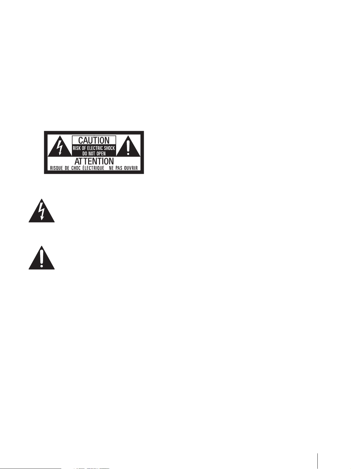
Ce symbole est destiné à avertir
l’utilisateur de la présence d’une « tension
dangereuse » non isolée dans l’enveloppe
du produit, qui pourrait être
suffisamment importante pour
représenter un risque d’électrocution pour
les personnes.
Ce symbole est destiné à avertir
l’utilisateur de la présence d’instructions
d’utilisation et de maintenance (entretien/
réparation) importantes dans la
documentation accompagnant l’appareil.
En cas d’utilisation aux États-Unis, utilisez le cordon
d’alimentation RÉPERTORIÉ UL indiqué ci-dessous.
N’UTILISEZ AUCUN AUTRE CORDON
D’ALIMENTATION.
Bouchon de fiche Lame parallèle avec broche de terre
(configuration NEMA 5-15P)
Cordon Type SJT ou SVT, trois fils 16 ou 18
AWG
Longueur Minimum 1,5 m (4 pieds 11 pouces),
moins de 2,5 m (8 pieds 3 pouces)
Caractéristiques nominales Minimum 10 A, 125 V
L’utilisation de cet appareil à une tension autre que 120 V
peut nécessiter l’utilisation d’un type différent de cordon
ou de fiche de fixation, ou les deux. Afin de réduire les
risques d’incendie ou d’électrocution, faites appel à un
technicien qualifié pour toute réparation/entretien.
AVERTISSEMENT : CET AVERTISSEMENT
S’APPLIQUE AUX AUTRES PAYS.
1. Utilisez un cordon d’alimentation (câble secteur à 3
fils)/fiche femelle/fiche mâle avec des contacts de
mise à la terre conformes à la réglementation de
sécurité locale applicable.
2. Utilisez un cordon d’alimentation (câble secteur à 3
fils)/fiche femelle/fiche mâle avec des
caractéristiques nominales (tension, ampérage)
appropriées.
Pour toute question sur l’utilisation du cordon
d’alimentation/fiche femelle/fiche mâle ci-dessus,
consultez un technicien du service après-vente qualifié.
Pour les clients au Canada
CAN ICES-3 (A)/NMB-3(A)
AT T EN T IO N
Eviter d’exposer l’appareil à un égouttement ou à des
éclaboussures. Ne placer aucun objet rempli de liquide,
comme un vase, sur l’appareil.
AT T EN T IO N
Cet appareil n’est pas déconnecté de la source
d’alimentation secteur tant qu’il est raccordé à la prise
murale, même si l’appareil lui-même a été mis hors
tension.
AVERTISSEMENT
Une pression acoustique excessive en provenance des
écouteurs ou du casque peut provoquer une baisse de
l’acuité auditive.
Pour utiliser ce produit en toute sécurité, évitez l’écoute
prolongée à des pressions sonores excessives.
AVERTISSEMENT :CET AVERTISSEMENT
S’APPLIQUE AUX ÉTATS-UNIS UNIQUEMENT.
Pour les clients en Europe
Ce produit portant la marque CE est conforme à la
Directive sur la compatibilité électromagnétique (EMC)
émise par la Commission de la Communauté
européenne.
La conformité à cette directive implique la conformité
aux normes européennes suivantes:
EN55103-1: Interférences électromagnétiques
(émission)
EN55103-2: Sensibilité électromagnétique (immunité)
Ce produit est prévu pour être utilisé dans
l’environnement électromagnétique suivant: E4
(environnement EMC contrôlé, ex. studio de télévision).
Pour les clients en Europe
Ce produit a été fabriqué par ou pour le compte de Sony
Corporation, 1-7-1 Konan Minato-ku Tokyo, 108-0075
Japon. Toutes les questions relatives à la conformité des
produits basées sur la législation européenne doivent
être adressées à son représentant, Sony Deutschland
5
Page 6
GmbH, Hedelfinger Strasse 61, 70327 Stuttgart,
Allemagne.
Pour toute question relative au Service Après-Vente ou à
la Garantie, merci de bien vouloir vous référer aux
coordonnées qui vous sont communiquées dans les
documents « Service (SAV) » ou Garantie.
Ne pas utiliser cet appareil dans une zone résidentielle.
Pour les clients en Europe, Australie et NouvelleZélande
AVERTISSEMENT
Il s’agit d’un produit de Classe A. Dans un
environnement domestique, cet appareil peut provoquer
des interférences radio, dans ce cas l’utilisateur peut être
amené à prendre des mesures appropriées.
Pour les clients au Canada
GARANTIE LIMITÉE DE SONY
http://www.sonybiz.ca/solutions/Support.do
- Rendez-vous sur
pour
obtenir les informations importantes et l’ensemble des
termes et conditions de la garantie limitée de Sony
applicable à ce produit.
WARNUN G
Um die Gefahr von Bränden oder elektrischen
Schlägen zu verringern, darf dieses Gerät nicht
Regen oder Feuchtigkeit ausgesetzt werden.
Um einen elektrischen Schlag zu vermeiden, darf
das Gehäuse nicht geöffnet werden. Überlassen
Sie Wartungsarbeiten stets nur qualifiziertem
Fachpersonal.
DIESES GERÄT MUSS GEERDET WERDEN.
WAR NUN G
Beim Einbau des Geräts ist daher im Festkabel ein leicht
zugänglicher Unterbrecher einzufügen, oder der
Netzstecker muss mit einer in der Nähe des Geräts
befindlichen, leicht zugänglichen Wandsteckdose
verbunden werden. Wenn während des Betriebs eine
Funktionsstörung auftritt, ist der Unterbrecher zu
betätigen bzw. der Netzstecker abzuziehen, damit die
Stromversorgung zum Gerät unterbrochen wird.
VORSICHT
Das Gerät ist nicht tropf- und spritzwassergeschützt. Es
dürfen keine mit Flüssigkeiten gefüllten Gegenstände,
z. B. Vasen, darauf abgestellt werden.
WAR NUNG
Zu hoher Schalldruck von Ohrhörern und Kopfhörern
kann Gehörschäden verursachen.
Um dieses Produkt sicher zu verwenden, vermeiden Sie
längeres Hören bei sehr hohen Schalldruckpegeln.
WAR NUNG
1. Verwenden Sie ein geprüftes Netzkabel (3-adriges
Stromkabel)/einen geprüften Geräteanschluss/einen
geprüften Stecker mit Schutzkontakten entsprechend
den Sicherheitsvorschriften, die im betreffenden
Land gelten.
2. Verwenden Sie ein Netzkabel (3-adriges
Stromkabel)/einen Geräteanschluss/einen Stecker
mit den geeigneten Anschlusswerten (Volt, Ampere).
Wenn Sie Fragen zur Verwendung von Netzkabel/
Geräteanschluss/Stecker haben, wenden Sie sich bitte an
qualifiziertes Kundendienstpersonal.
Für Kunden in Europa
Dieses Produkt besitzt die CE-Kennzeichnung und
erfüllt die EMV-Richtlinie der EG-Kommission.
Angewandte Normen:
EN55103-1: Elektromagnetische Verträglichkeit
(Störaussendung)
EN55103-2: Elektromagnetische Verträglichkeit
(Störfestigkeit)
Für die folgende elektromagnetische Umgebung: E4
(kontrollierter EMV-Bereich, z.B. Fernsehstudio).
Für Kunden in Europa
Dieses Produkt wurde von oder für Sony Corporation,
1-7-1 Konan Minato-ku Tokio, 108-0075 Japan
hergestellt.
Bei Fragen zur Produktkonformität auf Grundlage der
Gesetzgebung der Europäischen Union kontaktieren Sie
bitte den Bevollmächtigten Sony Deutschland GmbH,
Hedelfinger Strasse 61, 70327 Stuttgart, Deutschland.
Für Kundendienst oder Garantieangelegenheiten
wenden Sie sich bitte an die in den Kundendienst- oder
Garantiedokumenten genannten Adressen.
Dieser Apparat darf nicht im Wohnbereich verwendet
werden.
Für Kunden in Europa, Australien und Neuseeland
WAR NUNG
Dies ist eine Einrichtung, welche die Funk-Entstörung
nach Klasse A besitzt. Diese Einrichtung kann im
Wohnbereich Funkstörungen verursachen; in diesem
Fall kann vom Betreiber verlangt werden, angemessene
Maßnahmen durchzuführen und dafür aufzukommen.
VORSICHT
Solange das Netzkabel an eine Netzsteckdose
angeschlossen ist, bleibt das Gerät auch im
ausgeschalteten Zustand mit dem Stromnetz verbunden.
6
For kundene i Norge
Dette utstyret kan kobles til et ITstrømfordelingssystem.
Page 7
Apparatet må tilkoples jordet stikkontakt
Suomessa asuville asiakkaille
Laite on liitettävä suojamaadoituskoskettimilla
varustettuun pistorasiaan
För kunderna i Sverige
Apparaten skall anslutas till jordat uttag
Інформація для споживачів в Україні.
Обладнання відповідає вимогам:
– Технічного регламенту обмеження використання
деяких небезпечних речовин в електричному та
електронному обладнанні (постанова КМУ від 03/
12/2008 № 1057).
Türkiye’deki müşteriler için
AEEE Yönetmeliğine Uygundur
7
Page 8

Table of Contents
Precaution ....................................................... 9
On Safety .................................................................. 9
On Installation ......................................................... 9
Handling the Screen ............................................... 9
On Burn-in .............................................................. 9
On a Long Period of Use ......................................10
On High Brightness Display ................................ 10
On the Surface of the Unit ................................... 10
On Long Periods of Continuous Use .................. 10
Handling and Maintenance of the Screen .......... 10
On Dew Condensation ......................................... 10
On Repacking ........................................................ 10
Disposal of the Unit .............................................. 10
On Fan Error .......................................................... 11
Location and Function of Parts and
Controls ........................................................ 12
Front Panel............................................................. 12
Input Signals and Adjustable/Setting Items....... 14
Rear Panel .............................................................. 15
Connecting the AC Power Cord ................... 16
Using the Menu .............................................16
Protection of the Setting Values ...................17
Protecting the setting values using the KEY
INHIBIT button .................................................. 17
Protecting the setting values using [Password
Lock] ..................................................................... 17
Adjustment Using the Menus ....................... 18
Items ........................................................................ 18
Adjusting and Changing the Settings ................. 18
[Status] menu ................................................... 18
[User Preset Setting] menu ............................ 19
[Color Temp.] menu ....................................... 19
[User Configuration] menu ...........................20
[Security] menu ............................................... 24
Connecting the SDI Signals .......................... 24
Troubleshooting ...........................................25
Specifications ................................................ 25
Available Signal Formats...................................... 26
Dimensions ................................................... 31
8
Table of Contents
Page 9

Precaution
On Safety
Operate the unit only with a power source as specified
in the “Specifications” section.
A nameplate indicating operating voltage, etc., is
located on the rear panel.
Should any solid object or liquid fall into the cabinet,
unplug the unit and have it checked by qualified
personnel before operating it any further.
Do not drop or place heavy objects on the power cord.
If the power cord is damaged, turn off the power
immediately. It is dangerous to use the unit with a
damaged power cord.
Unplug the unit from the wall outlet if it is not to be
used for several days or more.
Disconnect the power cord from the AC outlet by
grasping the plug, not by pulling the cord.
The socket-outlet shall be installed near the
equipment and shall be easily accessible.
On Installation
Allow adequate air circulation to prevent internal heat
build-up.
Do not place the unit on surfaces (rugs, blankets, etc.)
or near materials (curtains, draperies) that may block
the ventilation holes.
Do not install the unit in a location near heat sources
such as radiators or air ducts, or in a place subject to
direct sunlight, excessive dust, mechanical vibration or
shock.
When installing the installation space must be secured
in consideration of the ventilation and service operation.
Do not block the ventilation slots, and vents of the
fans.
Leave a space around the unit for ventilation.
Leave more than 40 cm of space in the rear of the unit
to secure the operation area.
When the unit is installed on the desk or the like, leave at
least 10 cm of space in the top side. Leaving 40 cm or
more of space in the rear of the unit is recommended for
service operation.
Handling the Screen
The OLED panel fitted to this unit is manufactured
with high precision technology, giving a functioning
pixel ratio of at least 99.99%. Thus a very small
proportion of pixels may be “stuck”, either always off
(black), always on (red, green, or blue), or flashing. In
addition, over a long period of use, because of the
physical characteristics of the organic light-emitting
diode, such “stuck” pixels may appear spontaneously.
These problems are not a malfunction.
Do not leave the screen facing the sun as it can damage
the screen. Take care when you place the unit by a
window.
Do not push or scratch the monitor’s screen. Do not
place a heavy object on the monitor’s screen. This may
cause the screen to lose uniformity.
The screen and the cabinet become warm during
operation. This is not a malfunction.
On Burn-in
Due to the characteristics of the material used in the
OLED panel, permanent burn-in or reduction in
brightness may occur.
These problems are not a malfunction.
Images that may cause burn-in
Still images in the HDR display
Masked images with aspect ratios other than 17:9
Color bars or images that remain static for a long time
Character or message displays that indicate settings or
the operating state
On-screen displays such as center markers or area
markers
For details on the HDR (High Dynamic Range) display, see
page 21.
To reduce the risk of burn-in
Turn off the character and marker displays
Press the MENU button to turn off the character
displays. To turn off the character or marker displays
of the connected equipment, operate the connected
equipment accordingly. For details, refer to the
operation manual of the connected equipment.
Do not display static images that contain high
brightness display, time codes, markers, or logos for
extended periods. Consider applying a display method
with low level signals of 100% or less.
Turn off the power when not in use
Turn off the power if the monitor is not to be used for
a prolonged period of time.
Screen saver
This product has a built-in screen saver function to
reduce burn-in. When an almost still image is displayed
for more than 10 minutes, the screen saver starts
automatically and the brightness of the screen decreases.
Precaution
9
Page 10

On a Long Period of Use
Handling and Maintenance of the
Due to an OLED’s panel structure and characteristics of
materials in its design, displaying static images for
extended periods, or using the unit repeatedly in a high
temperature/high humidity environments may cause
image smearing, burn-in, areas of which brightness is
permanently changed, lines, or a decrease in overall
brightness.
In particular, continued display of an image smaller than
the monitor screen, such as in a different aspect ratio,
may shorten the life of the unit.
Avoid displaying a still image for an extended period, or
using the unit repeatedly in a high temperature/high
humidity environment such an airtight room, or around
the outlet of an air conditioner.
To prevent any of the above issues, we recommend
reducing brightness slightly, and to turn off the power
whenever the unit is not in use.
On High Brightness Display
Using the unit with the high brightness display for
extended periods may cause eyestrain or reduction of
eyesight. Be sure to take an occasional break when
using.
Follow RECOMMENDATION ITU-R BT.1702
“Guidance for the reduction of photosensitive
epileptic seizures caused by television” or other
guidelines when using.
In the HDR display, the display surface may emit heat
when high brightness images are output. Do not touch
the surface.
For details on the HDR (High Dynamic Range) display, see
page 21.
Screen
The surface of the screen is specially coated to reduce
image reflection. Make sure to observe the following
points as improper maintenance procedures may impair
the screen’s performance. In addition, the screen is
vulnerable to damage. Do not scratch or knock against it
using a hard object.
Be sure to disconnect the AC power cord from the AC
outlet before performing maintenance.
The surface of the screen is specially coated. Do not
attach adhesive objects, such as stickers, on it.
The surface of the screen is specially coated. Do not
touch the screen directly.
Wipe the screen surface gently with the supplied
cleaning cloth or a soft dry cloth to remove dirt.
Stubborn stains may be removed with the supplied
cl eaning cloth, or a sof t cloth slightly d ampened wi th a
mild detergent solution.
The screen may become scratched if the cleaning cloth
is dusty.
Never use strong solvents such as alcohol, benzene,
thinner, acidic or alkaline detergent, detergent with
abrasives, or chemical wipe as these may damage the
screen.
Use a blower to remove dust from the screen surface.
On Dew Condensation
If the unit is suddenly taken from a cold to a warm
location, or if ambient temperature suddenly rises,
moisture may form on the outer surface of the unit and/
or inside of the unit. This is known as condensation. If
condensation occurs, turn off the unit and wait until the
condensation clears before operating the unit. Operating
the unit while condensation is present may damage the
unit.
On the Surface of the Unit
The surface of the unit becomes extremely hot. Do not
touch the surface with your hand or body during power
distribution. It may cause a burn.
On Long Periods of Continuous Use
Using this unit for extended periods may cause eyestrain
or reduction of eyesight.
As soon as you feel physical discomfort or pain, stop
using this unit immediately and take a break.
If the physical discomfort or pain remains even after
taking a break, consult a physician.
10
Precaution
On Repacking
Do not throw away the carton and packing materials.
They make an ideal container which to transport the
unit.
Disposal of the Unit
Do not dispose of the unit with general waste.
Do not include the monitor with household waste.
When you dispose of the monitor, you must obey the
law in the relative area or country.
Page 11

On Fan Error
The unit has a built in fan for cooling. When the fan
stops and the (Power) switch indicator blinks in red,
turn off the power and contact an authorized Sony
dealer.
Precaution
11
Page 12
Location and Function of Parts and Controls
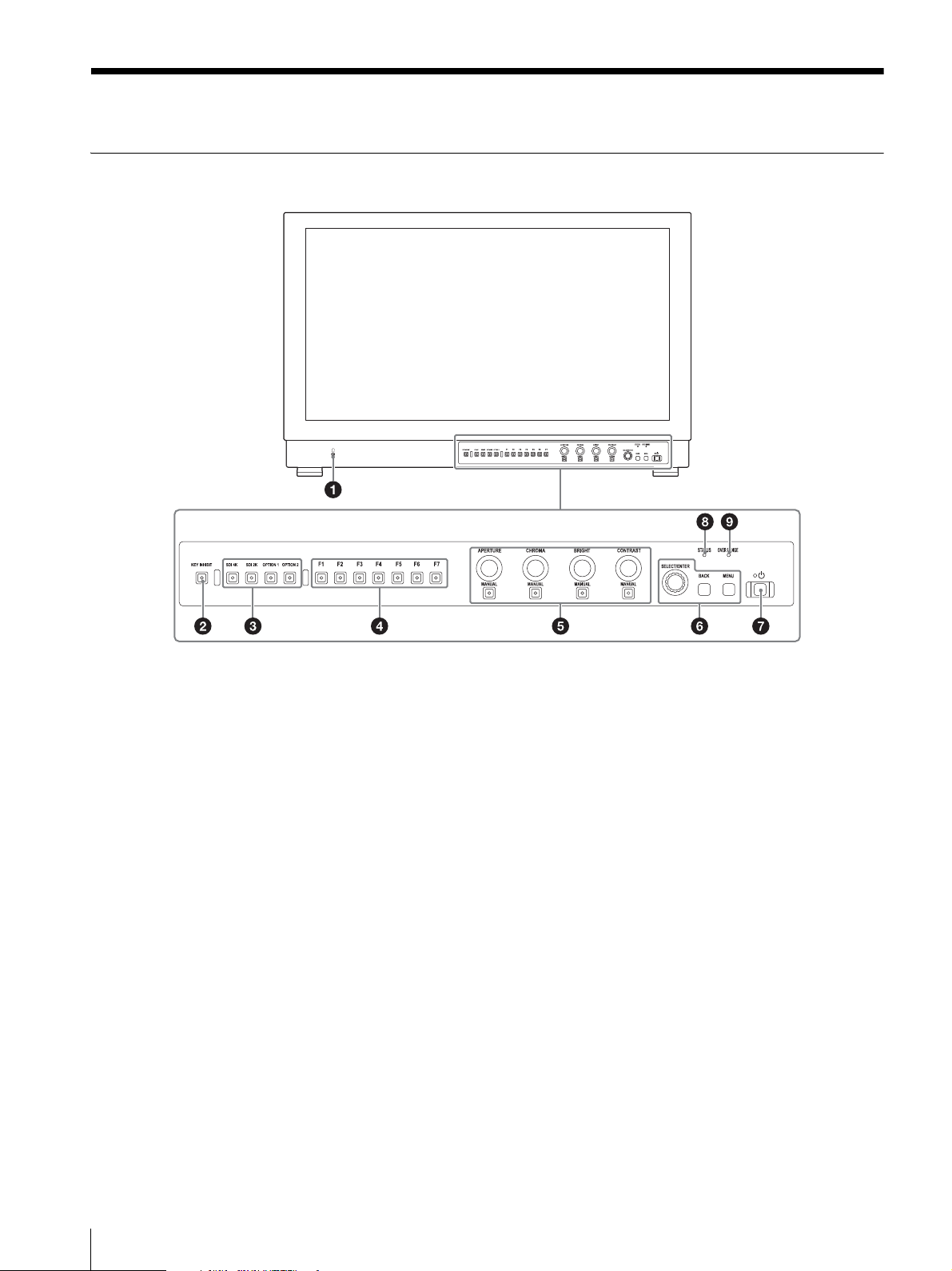
Front Panel
(headphones) jack
This is for future function expansion. When expanding
the function, the audio signal which is selected by the
input select button is output in stereo sound.
KEY INHIBIT button
You can turn the setting value protection on or off.
When the setting value is protected with key inhibit, the
value cannot be changed. To change the setting value,
turn protection off by pressing the button for more than
two seconds.
For details, see “Protection of the Setting Values”
(page 17).
Input select buttons
Press to monitor the signal input to each connector.
SDI 4K button: to monitor the 4K signal through the
SDI IN connector
SDI 2K button: to monitor the 2K signal through the
SDI IN connector
OPTION1/OPTION2 button: For future function
expansion.
Function buttons
You can turn the assigned function on or off.
The factory setting is as follows;
F1 button: [Mono]
F2 button: [Flicker Free]
F3 button: [Blue Only]
F4 button: [Internal Signal]
F5 button: [User Preset1]
F6 button: [User Preset2]
F7 button: [User Preset3]
You can assign various functions in [Function Button
Setting] (page 23) of the [User Configuration] menu.
Rotary encoder
APERTURE knob: Adjusts the picture sharpness.
Turn the knob to the right to make picture sharper and
turn it to the left to make the picture softer. This
adjustment is available while the indicator of the
MANUAL button below the knob is lit.
CHROMA knob: Adjusts the color intensity. Turn the
knob to the right to increase the intensity and turn to
the left to decrease it. This adjustment is available
while the adjustment menu is displayed or the
indicator of the MANUAL button below the knob is lit.
BRIGHT knob: Adjusts the picture brightness. Turn
the knob to the right to increase the brightness and
turn to the left to decrease it. This adjustment is
available while the adjustment menu is displayed or
12
Location and Function of Parts and Controls
Page 13
the indicator of the MANUAL button below the knob
is lit.
CONTRAST knob: Adjusts the picture contrast. Turn
the knob to the right to increase the contrast and turn
to the left to decrease it. This adjustment is available
while the adjustment menu is displayed or the
indicator of the MANUAL button below the knob is lit.
MANUAL button: Press to perform the adjustment
manually with the knob. Each time the button is
pressed, the button indicator lights up or goes out.
Each adjustment is available with the knobs above
each indicator while it is lit.
Menu operation buttons
Displays or sets the on-screen menu.
Menu selection control
When the menu is displayed, turn the control to select
a menu item or setting value, and then press the
control to confirm the setting.
If the menu is not displayed and the menu selection
control is pressed, the characters that represent the
names of the buttons light up. Also, the names of the
functions assigned to the function buttons appear on
the screen. Press again to clear it.
Alternatively, if the menu is not displayed and the
menu selection control is pressed for more than two
seconds, the signal format is displayed on the screen.
BACK button
When the menu is displayed, press the button to reset
the value of an item to the previous value (except some
items).
MENU button
Press to display the on-screen menu.
Press again to clear the menu.
(Power) switch and indicator
When the unit is turned off, press the switch to turn it
on. When the unit turns on, the unit starts up with the
indicator flashing in green. When the unit is in
operation, the indicator lights in green.
Press the switch again to turn off the unit. The indicator
goes out.
Lights in amber when ABL (Automatic Brightness
Limiter) starts.
About error/warning signals of the indicator
While the unit is in use, the (Power) switch indicator
or OVER RANGE indicator of the front panel may show
error or warning signals.
If an error display appears, refer to Sony qualified service
personnel.
Error display
OVER RANGE
indicator
–Flashes in red
–Flashes in red
Warning display
OVER RANGE
indicator
Flashes in
amber (every
second)
Lights in amber – ABL starts
1) When [2.4(HDR)], [S-Log3(HDR)], or [S-Log2(HDR)] is
set for [EOTF] in the [Input Setting] menu, regardless of
the input signal, the screen brightness may decrease due to
the protective function for the OLED panel activates. To
avoid the brightness decrease due to the protection
function, it is recommended to keep the temperature of the
peripheral environment of the unit around 25 °C.
For details on the HDR (High Dynamic Range) display, see
page 21.
Power
indicator
(every second)
(every two
seconds)
Power
indicator
– Decreases the brightness to
Symptom
Power abnormality, circuit
board abnormality, sensor
abnormality
Fan abnormality
Symptom
protect the panel from
overheating
1)
STATUS indicator
Slowly flashes in yellow when the screen saver starts up,
and quickly flashes in yellow when a warning during
startup occurs.
Lights up in blue in the HDR display mode. Slowly
flashes in blue when the screen saver displaying in HDR
starts up, and quickly flashes in blue when a warning
during startup occurs.
For details on the HDR (High Dynamic Range) display, see
page 21.
OVER RANGE indicator
Location and Function of Parts and Controls
13
Page 14
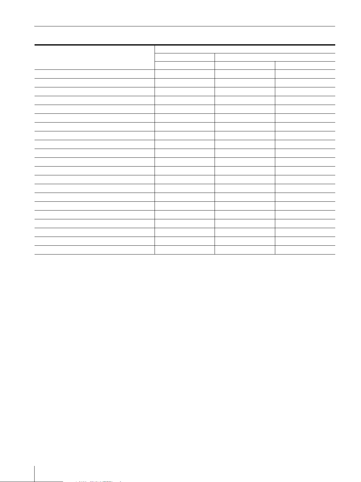
Input Signals and Adjustable/Setting Items
Item
APERTURE
CHROMA
BRIGHT
CONTRAST
User Preset
Color Temp.
Manual Adjustment (Color Temp.)
Flicker Free
Screen Saver
RGB Range
Color Space
EOTF
Transfer Matrix
Internal Signal
Internal Signal Pattern
Mono
Blue Only
R Off
G Off
B Off
Character Off
: Adjustable/can be set
1)
1)
2)
3)
SDI 4K SDI 2K
Quad Link Dual Link Single Link
Input signal
1) The available maximum brightness is reduced by half
when the interlace signal is input.
2) Available only during SDR (Standard Dynamic Range)
display.
3) The setting is available only when the RGB signal is input.
14
Location and Function of Parts and Controls
Page 15
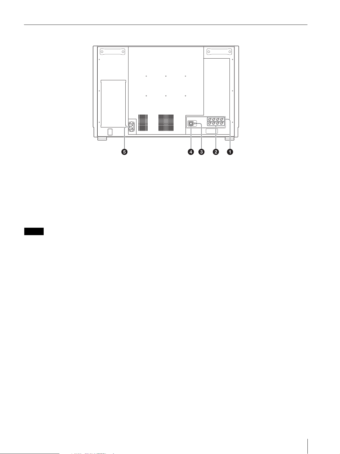
Rear Panel
Note
SDI IN (SDI input) connectors (BNC)
Input connectors for serial digital signals.
For details, see “Connecting the SDI Signals” (page 24).
SDI OUT (SDI output) connectors (BNC)
Output connectors for serial digital signals.
The to connectors outputs the signal that is input
to the corresponding SDI IN connector.
SDI output is only activated when the power is on.
AUDIO output connector (stereo mini jack)
This is for future function expansion.
When the function is expanded, the audio signal of the
signal which is selected by the input select button on the
front panel is output.
LAN (10/100) connector
Used for future expansion.
Connect to the LAN (10/100) connector of the network
by using a 10BASE-T/100BASE-TX LAN cable.
CAUTION
For safety, do not connect the connector for peripheral
device wiring that might have excessive voltage to this
port. Follow the instructions for this port.
When you connect the LAN cable of the unit to
peripheral device, use a shielded-type cable to prevent
malfunction due to radiation noise.
VORSICHT
Aus Sicherheitsgründen nicht mit einem
Peripheriegerät-Anschluss verbinden, der zu starke
Spannung für diese Buchse haben könnte. Folgen Sie
den Anweisungen für diese Buchse.
AC IN socket
Connect the supplied AC power cord.
AT TE NT IO N
Par mesure de sécurité, ne raccordez pas le connecteur
pour le câblage de périphériques pouvant avoir une
tension excessive à ce port. Suivez les instructions pour
ce port.
Location and Function of Parts and Controls
15
Page 16
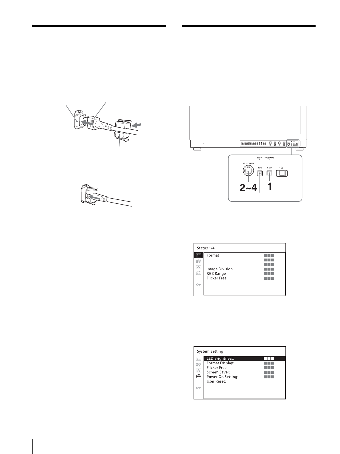
Connecting the AC Power
AC IN socket
AC power cord
AC plug holder
(supplied)
BACK button
Cord
1
Plug the AC power cord into the AC IN socket on
the rear panel. Then, attach the AC plug holder
(supplied) to the AC power cord.
2
Slide the AC plug holder over the cord until it locks.
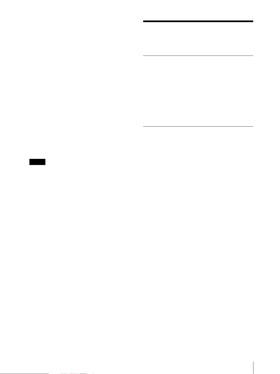
Using the Menu
The unit is equipped with an on-screen menu for
making various adjustments and settings such as picture
control, input setting, set setting change, etc.
The current settings are displayed in place of the
marks on the illustrations of the menu screen.
To remove the AC power cord
Pull out the AC plug holder while pressing the lock
levers.
1
Press the MENU button.
The menu appears.
The menu presently selected is shown in yellow.
2
Turn the menu selection control to select a menu,
then press the menu selection control.
The menu icon presently selected is shown in
yellow and setting items are displayed.
16
Connecting the AC Power Cord / Using the Menu
3
Select an item.
Page 17
Turn the menu selection control to select the item,
Notes
then press the menu selection control.
The item to be changed is displayed in yellow.
If the menu consists of multiple pages, turn the
menu selection control to go to the desired menu
page.
Protection of the Setting Values
4
Make the setting or adjustment on an item.
When changing the adjustment level:
To increase the number, turn the menu selection
control right.
To decrease the number, turn the menu selection
control left.
Press the menu selection control to confirm the
number, then restore the original screen.
When changing the setting:
Turn the menu selection control to change the
setting, then press the menu selection control to
confirm the setting.
When returning the adjustment or setting to the
previous value:
Press the BACK button before pressing the menu
selection control.
An item displayed in black cannot be accessed.
You can access the item if it is displayed in white.
If the [Password Lock] has been turned [On], the
setting values of the color temperature for [User1]
and the User Preset for [User Preset1] cannot be
changed. To change the values, enter the
password.
For details on the password lock function, see
“[Security] menu” (page 24).
Protecting the setting values using the KEY INHIBIT button
You can protect the setting values using the KEY
INHIBIT button.
When the values are protected by the key inhibit
function, you cannot change the values.
To change the values, press and hold the KEY INHIBIT
button to set the protection of the setting value to off.
Protecting the setting values using [Password Lock]
You can protect the setting values of the color
temperature for [User1] and the User Preset for [User
Preset1] using [Password Lock].
When the values are protected with a password, you
need to enter the password during the following
operations.
When you change the color temperature values for
[User1] using [Adjust Gain/Bias] or [Copy From].
When you change the User Preset values for [User
Preset1].
For details, see [Password Lock] (page 24).
To return the display to the previous screen
Press the BACK button.
To clear the menu
Press the MENU button.
The menu disappears automatically if a button is not
pressed for one minute.
About the memory of the settings
The settings are automatically stored in the monitor
memory.
Protection of the Setting Values
17
Page 18
Adjustment Using the Menus
[Security]
[Password Lock]
[Color Temp./User Pre.]
[Change Password]
Items
The screen menu of this monitor consists of the
following items.
[Status] (the items indicate the current
settings.)
Displays the unit setting status, etc.
For details on the displayed items, see “[Status] menu”
(page 18).
[User Preset Setting]
[User Preset]
[Color Temp.]
[Contrast]
[Brightness]
[Chroma]
[Aperture]
[Copy From]
[Color Temp.]
[Color Temp.]
[R/G/B Gain]
[R/G/B Bias]
[Manual Adjustment]
[Adjust Gain/Bias]
[Signal]
[Copy From]
Adjusting and Changing the Settings
[Status] menu
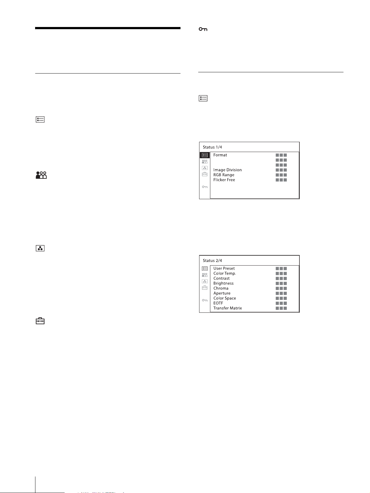
The status menu displays the current status of the unit.
The following items are displayed:
Page 1
[Format]
[Image Division]
[RGB Range]
[Flicker Free]
Page 2
[User Configuration]
[System Setting]
[LED Brightness]
[Format Display]
[Flicker Free]
[Screen Saver]
[Power On Setting]
[User Reset]
[Input Setting]
[SDI 4K Input]
[4K/UHD Input Setting]
[SDI 2K Input]
[2K/HD Input Setting]
[Function Button Setting]
[Internal Signal Setting]
[Internal Signal]
[Pattern]
18
Adjustment Using the Menus
[User Preset]
[Color Temp.]
[Contrast]
[Brightness]
[Chroma]
[Aperture]
[Color Space]
[EOTF]
[Transfer Matrix]
Page 19
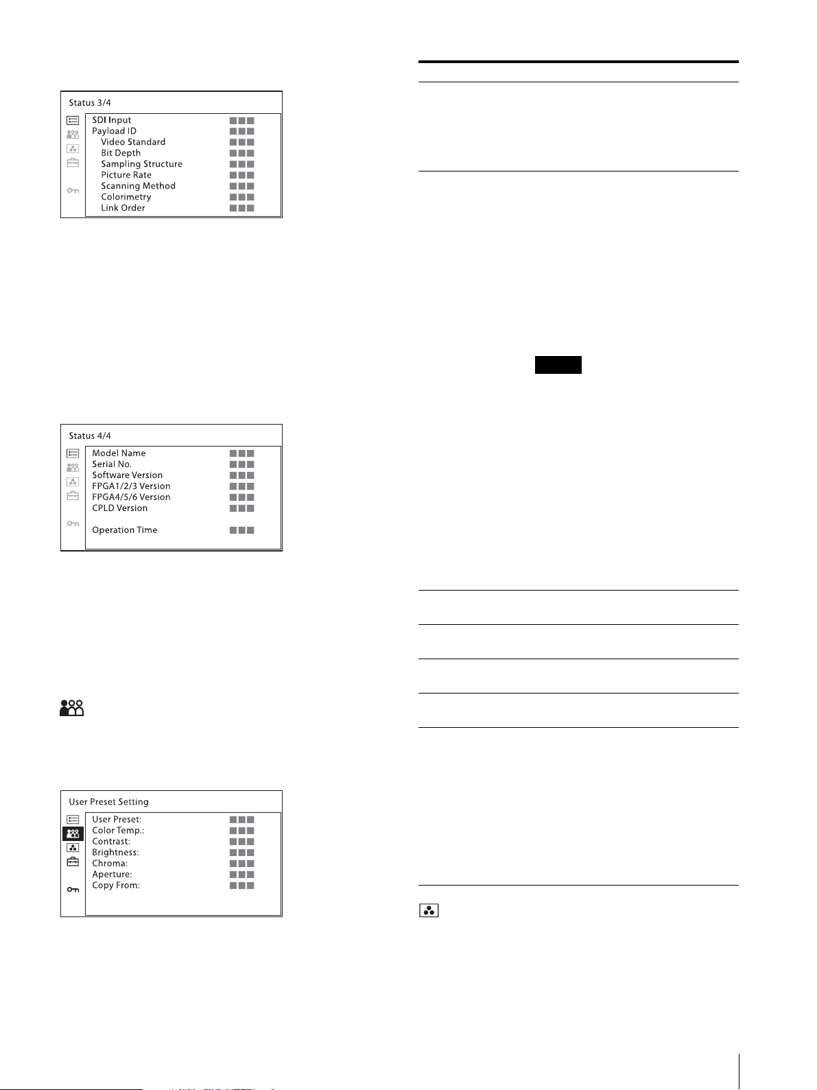
Page 3
Note
[SDI Input]
[Payload ID]
[Video Standard]
[Bit Depth]
[Sampling Structure]
[Picture Rate]
[Scanning Method]
[Colorimetry]
[Link Order]
Page 4
[Model Name]
[Serial No.]
[Software Version]
[FPGA1/2/3 Version]
[FPGA4/5/6 Version]
[CPLD Version]
[Operation Time]
[User Preset Setting] menu
You can select the User Preset to be used, or set and
adjust various items. The preset values can be copied
from other preset data.
Submenu Setting
[User Preset] Select the User Preset data to be applied.
[User Preset1]
[User Preset2]
[User Preset3]
[User Preset4]
[User Preset5]
[Color Temp.] Select the color temperature to be used
in the selected User Preset.
[D65]
[D93]
[D61]
[D55]
[DCI]
[User1]
[User2]
[User3]
[User4]
[User5]
If you measure the color temperatures
of different display types, such as CRT,
LCD, or OLED, by using a common (or
general) color analyzer that is based on
CIE 1931, and adjust the xy
chromaticity to the same value, the
appearance may be different because of
optical spectrum differences.
To compensate for this difference, the
[D65], [D93], [D61], [D55], and [DCI]
settings of the monitor are adjusted by
an offset
1)
.
1) The offset value applied (x-0.006, y-
0.011) is based on the Judd’s function
to the CIE 1931 (x, y) value.
[Contrast] Set the contrast of the selected User
Preset.
[Brightness] Set the brightness of the selected User
Preset.
[Chroma] Set the chroma level of the selected User
Preset.
[Aperture] Set the aperture of the selected User
Preset.
[Copy From] Copies the other User Preset data to the
selected User Preset. The appropriate
settings are saved in [Default(D65)] for
D65 and [Default(D93)] for D93.
[User Preset1]
[User Preset2]
[User Preset3]
[User Preset4]
[User Preset5]
[Default(D65)]
[Default(D93)]
[Color Temp.] menu
You can select and adjust the color temperature.
You need to use the measurement instrument to adjust
the white balance.
Recommended: Konica Minolta Color Analyzer CA210/310
Adjustment Using the Menus
19
Page 20
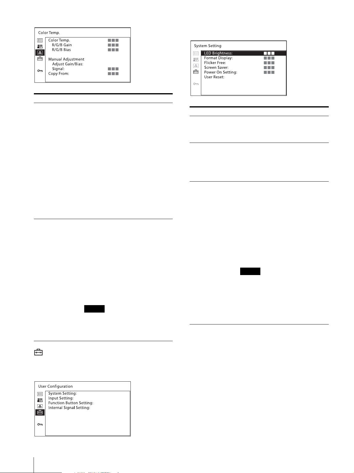
Submenu Setting
Note
Note
[Manual Adjustment] If you set the [Color Temp.] to the
[User1] to [User5] setting, you can
adjust the color temperature.
The set values are memorized.
[Adjust Gain/Bias]:
[R/G/B Gain]: Adjusts the
color balance (gain) of R (red)/
G (green)/B (blue).
[R/G/B Bias]: Adjusts the
color balance (bias) of R
(red)/G (green)/B (blue).
[Signal]:
[Internal]: Select to adjust the
white balance by using the
internal signal.
[External]: Select to adjust the
white balance by using the
signals input from an external
device.
[Copy From] Select from the following items to copy
the white balance data of the selected
color temperature.
[D65]
[D93]
[D61]
[D55]
[DCI]
[User1]
[User2]
[User3]
[User4]
[User5]
If [Password Lock] has been turned
[On], the [User1] value is protected by a
password. To change the values, enter
the password.
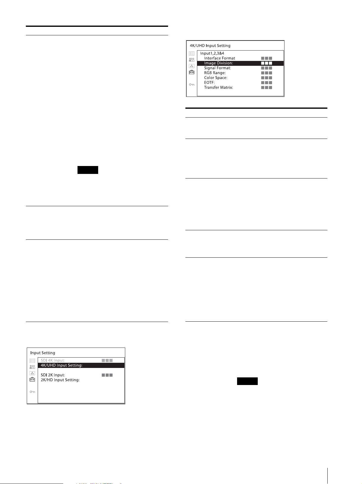
[System Setting]
Submenu Setting
[LED Brightness] Selects the brightness of the indicator’s
LED of the buttons, power switch, etc.
[High]: The LED becomes brighter.
[Low]: The LED becomes darker.
[Format Display] Selects the display mode of the signal
format.
[Auto]: The format is displayed for
about five seconds when the
input of the signal starts.
[Off]: The display is hidden.
[Flicker Free] Set this to [On] to enable view images
without flicker.
An OLED panel can provide superior
video responsiveness and scan driving,
reproducing images with little contour
or afterimage. However, scan driving
can cause flicker when input signals
have a low vertical frequency (24P/PsF,
50i, etc.). Set [Flicker Free] to [On] to
greatly reduce this phenomenon.
With this mode set to on, quick-moving
images may exhibit contours or an
afterimage.
In the HDR display, [Flicker Free]
cannot be selected. [On] is always set
for signals of vertical frequency 24 Hz,
25 Hz, 48 Hz, and 50Hz. [Off] is always
set for signals of 30 Hz and 60 Hz.
For details on the HDR (High Dynamic
Range) display, see page 21.
[User Configuration] menu
Executes [System Setting], [Input Setting], [Function
Button Setting], and [Internal Signal Setting].
20
Adjustment Using the Menus
Page 21
Note
Submenu Setting
Note
[Screen Saver] Sets the screen saver function [On] or
[Off].
[On]: If a still image is displayed for
more than 10 minutes, the
brightness of the screen is
automatically decreased to
reduce burn-in. The screen
returns to normal brightness
when you input a video signal to
the unit or operate the buttons
on the front panel of the unit.
While the screen saver is active,
the STATUS indicator flashes
every two seconds. Before the
screen saver starts up, the
STATUS indicator flashes every
second to notify users that the
screen saver will start up.
[Off]: The screen saver function is
deactivated.
In the HDR display mode, this setting is
forcibly set to [On].
For details on the HDR (High Dynamic
Range) display, see page 21.
[Power On Setting] Sets this unit’s setting status after the
unit is turned on. Select from [Last
Memory], [User Preset1], [User
Preset2], [User Preset3], [User Preset4]
or [User Preset5].
[User Reset] Returns to the factory default setting
except for the following:
Color temperature for [User1]
Color temperature for [User2]
Color temperature for [User3]
Color temperature for [User4]
Color temperature for [User5]
User Preset for [User Preset1]
Password setting
[Cancel]: Cancels reset.
[Confirm]: Resets the unit. When
reset finishes, this unit restarts.
[Input Setting]
[4K/UHD Input Setting]
Submenu Setting
[Interface Format] Displays the interface format of the 4K
input.
[Quad-Link 3G/HD-SDI]
[Image Division] Set the image division of the 4K input.
[Auto]: Select for the Auto setting.
[2SI]: Select to receive images of the 2
sample Interleave system.
[Square]: Select to receive images of
the Square system.
[Signal Format] Select a signal format from the
following.
[Auto]
[422 YCbCr 10bit]
[444 RGB 10bit]
[444 YCbCr 10bit]
[444 RGB 12bit]
[444 YCbCr 12bit]
[RGB Range] Select from the following when [Signal
Format] is set to RGB.
[Full]
[Limited]
[Color Space] Select the color space from the
following:
[ITU-R BT.709]
[EBU]
[SMPTE-C]
[Native]
[S-Gamut/S-Gamut3]
[S-Gamut3.Cine]
[DCI-P3]
[ITU-R BT.2020]
[EOTF] Select the gamma from the following:
[2.2]
[2.4]
[2.6]
[CRT]
[2.4(HDR)]
[S-Log3(HDR)]
[S-Log2(HDR)]
When [2.4(HDR)], [S-Log3(HDR)], or
[S-Log2(HDR)] is selected, HDR (High
Dynamic Range) is displayed.
The HDR display is a method to
faithfully display the brightness of
signals defined of 100% or more level
without compressing the brightness
parts.
Adjustment Using the Menus
21
Page 22
Submenu Setting
In the HDR display, the cooling fan
is forcibly rotated regardless of
outside temperature.
In the HDR display, the screen saver
is forcibly set. [Off] cannot be
selected.
In the HDR display, [Flicker Free]
cannot be selected. [On] is always set
for signals of vertical frequency 24
Hz, 25 Hz, 48 Hz, and 50 Hz. [Off] is
always set for signals of 30 Hz and 60
Hz.
The protective function for the
OLED panel activates and inserts the
black level in one field according to
the input signal.
When the signal to display high
brightness images on the larger part
of the screen is input, blinking may
occur due to the protection function.
This is not a malfunction. There is
no effect on the throughout.
Using the unit with the high
brightness display for extended
periods may cause eyestrain or
reduction of eyesight. Be sure to take
an occasional break when using.
Follow RECOMMENDATION ITU-
R BT.1702 “Guidance for the
reduction of photosensitive epileptic
seizures caused by television” or
other guidelines to use.
In the HDR display, the display
surface may emit heat when high
brightness images are output. Do not
touch the surface.
Do not display static images that
contains high brightness display,
time codes, markers, or logos for
extended periods to reduce the risk
of burn-in. Consider to apply a
displaying method with a low level
signals of 100% or less.
[Transfer Matrix] Select the transfer matrix from the
following:
[ITU-R BT.709]
[ITU-R BT.2020]
[SDI 2K Input]
Setting
Set the input connector of the SDI 2K signals.
[Input1]: Select to input to Input 1 with Single Link.
[Input2]: Select to input to Input 2 with Single Link.
[Input3]: Select to input to Input 3 with Single Link.
[Input4]: Select to input to Input 4 with Single Link.
[Input1&2]: Select to use Input 1&2 with Dual Link.
[Input3&4]: Select to use Input 3&4 with Dual Link.
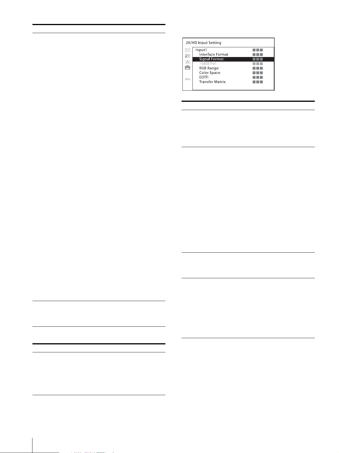
[2K/HD Input Setting]
Submenu Setting
[Interface Format] Displays the interface format of the 2K
input.
[Single-Link 3G/HD-SDI]: For
Single Link.
[Dual-Link 3G-SDI]: For Dual Link
of 3G-SDI.
[Signal Format] Select from the following when
[Interface Format] is [Single-Link 3G/
HD-SDI].
[Auto]
[422 YCbCr 10bit]
[444 RGB 10bit]
[444 YCbCr 10bit]
[444 RGB 12bit]
[444 YCbCr 12bit]
Select from the following when
[Interface Format] is [Dual-Link 3GSDI].
[Auto]
[444 RGB 10bit]
[444 YCbCr 10bit]
[444 RGB 12bit]
[444 YCbCr 12bit]
[RGB Range] Select from the following when [Signal
Format] is set to RGB.
[Full]
[Limited]
[Color Space] Select the color space from the
following:
[ITU-R BT.709]
[EBU]
[SMPTE-C]
[Native]
[S-Gamut/S-Gamut3]
[S-Gamut3.Cine]
[DCI-P3]
[ITU-R BT.2020]
[EOTF] Select the gamma from the following:
[2.2]
[2.4]
[2.6]
[CRT]
[2.4(HDR)]
[S-Log3(HDR)]
[S-Log2(HDR)]
22
Adjustment Using the Menus
Page 23
Note
Submenu Setting
When [2.4(HDR)], [S-Log3(HDR)], or
[S-Log2(HDR)] is selected, HDR (High
Dynamic Range) is displayed.
The HDR display is a method to
faithfully display the brightness of
signals defined of 100% or more level
without compressing the brightness
parts.
In the HDR display, the cooling fan
is forcibly rotated regardless of
outside temperature.
In the HDR display, the screen saver
is forcibly set. [Off] cannot be
selected.
In the HDR display, [Flicker Free]
cannot be selected. [On] is always set
for signals of vertical frequency 24
Hz, 25 Hz, 48 Hz, and 50 Hz. [Off] is
always set for signals of 30 Hz and 60
Hz.
The protective function for the
OLED panel activates and inserts the
black level in one field according to
the input signal.
When the signal to display high
brightness images on the larger part
of the screen is input, blinking may
occur due to the protection function.
This is not a malfunction. There is
no effect on the throughout.
Using the unit with the high
brightness display for extended
periods may cause eyestrain or
reduction of eyesight. Be sure to take
an occasional break when using.
Follow RECOMMENDATION ITU-
R BT.1702 “Guidance for the
reduction of photosensitive epileptic
seizures caused by television” or
other guidelines to use.
In the HDR display, the display
surface may emit heat when high
brightness images are output. Do not
touch the surface.
Do not display static images that
contains high brightness display,
time codes, markers, or logos for
extended periods to reduce the risk
of burn-in. Consider to apply a
displaying method with a low level
signals of 100% or less.
[Transfer Matrix] Select the transfer matrix from the
following:
[ITU-R BT.709]
[ITU-R BT.2020]
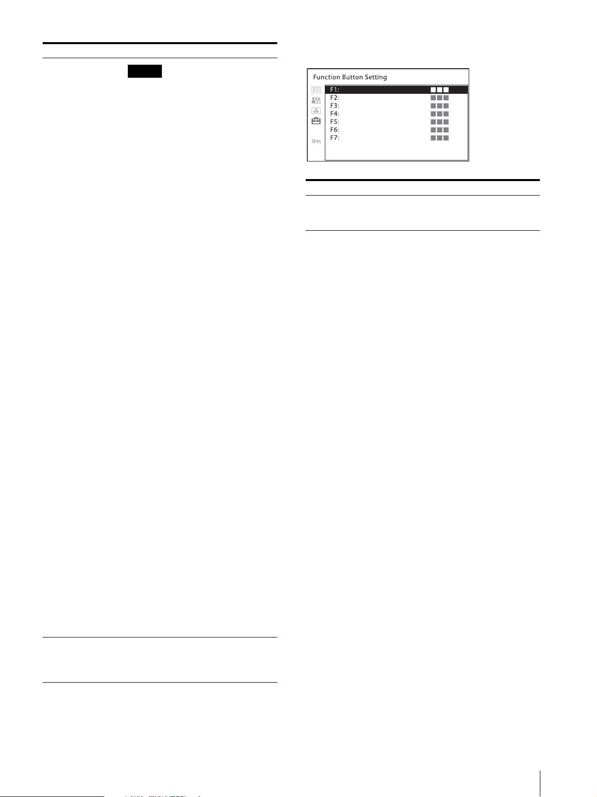
[Function Button Setting]
Submenu Setting
[F1] to [F7] Assigns functions to the function
buttons of the front panel and turns the
function on or off.
About functions assigned to the function
buttons
[Mono]
Press the button to display a monochrome picture.
When the button is pressed again, the monitor switches
automatically to color mode.
[Blue Only]
Press the button to eliminate the red and green signals.
Only the blue signal is displayed as an apparent
monochrome picture on the screen. This facilitates
observation of signal noise.
[Flicker Free]
Press the button to change the flicker free setting.
[R Off]
Press the button to turn off the R (red) signal.
[G Off ]
Press the button to turn off the G (green) signal.
[B Off]
Press the button to turn off the B (blue) signal.
[User Preset1]
[User Preset2]
[User Preset3]
[User Preset4]
[User Preset5]
Press the button to change the User Preset number. You
can check the setting status of the User Preset in the
[User Preset Setting] menu (page 19).
[Character Off]
Press the button to hide the menu while adjusting the
picture. When the button is pressed again, the monitor
switches to the previous display.
[Internal Signal]
Press the button to display the internal signal.
Adjustment Using the Menus
23
Page 24
[Internal Signal Pattern]
Press the button to change the pattern of the internal
signal when the internal signal is displayed. With every
press of the button, the picture switches between [White]
and [PLUGE].
Connecting the SDI Signals
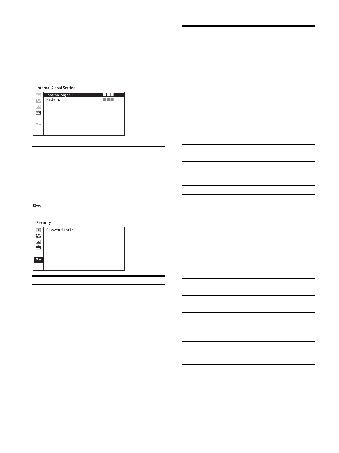
[Internal Signal Setting]
Submenu Setting
[Internal Signal] Select the internal signal display.
[On]
[Off]
[Pattern] Select the pattern of the internal signal.
[PLUGE]
[White]
[Security] menu
Single Link 3G/HD-SDI, Dual Link 3G-SDI, and Quad
Link 3G/HD-SDI signals can be input to the SDI IN
connectors of this unit.
Up to 4-channel Single Link 3G/HD-SDI signals, up to
2-channel Dual Link 3G/HD-SDI signals, or 1-channel
Quad Link 3G-SDI signals can be input. Use the
appropriate input connectors depending on the input
signal, referring to the tables below.
Connecting the Dual Link 3G-SDI signal
Connector Input signal
SDI IN 3G-SDI Link 1
SDI IN 3G-SDI Link 2
or
Connector Input signal
SDI IN 3G-SDI Link 1
SDI IN 3G-SDI Link 2
When only 1-channel Dual Link 3G-SDI signal is input,
the Single Link 3G/HD-SDI signals of up to 2 channels
can be input via the SDI IN connectors that are not used
for the Dual Link 3G-SDI signal.
Submenu Setting
[Password Lock] You can protect the setting with a
password so that the settings saved in
the color temperature for [User1] and
the User Preset for [User Preset1]
cannot be changed.
When you protect the values with a
password, set a four-digit number.
The initial password is “0000”. When
you use [Password Lock], change the
initial password first.
[Color Temp./User Pre.]: Select [On]
to protect the setting values
saved in the color temperature
for [User1] and the User Preset
for [User Preset1]. Select [Off ]
to not protect with the password.
[Change Password]: Changes the
password.
Connecting the Quad Link 3G/HD-SDI signal
To input 2-sample interleave division signals
Connector Input signal
SDI IN 3G-SDI Link 1
SDI IN 3G-SDI Link 2
SDI IN 3G-SDI Link 3
SDI IN 3G-SDI Link 4
To input Square division signals
Connector Input signal
SDI IN Mapping signal of Sub image 1 (upper-
left screen)
SDI IN Mapping signal of Sub image 2 (upper-
right screen)
SDI IN Mapping signal of Sub image 3 (lower-
left screen)
SDI IN Mapping signal of Sub image 4 (lower-
right screen)
24
Connecting the SDI Signals
Page 25

Troubleshooting
Specifications
This section may help you isolate the cause of a problem
and as a result, eliminate the need to contact technical
support.
The unit cannot be operated The key protection
function is on. Press and hold the KEY INHIBIT
button to set the protection of the setting value to off.
Or, a function that does not work is assigned to a
function button. When the menu is not displayed,
press the menu selection control to confirm the
functions assigned to function buttons.
The black bars appear at the left and right positions
of the display When the signal aspect ratio is
different from that of the panel, the black bars appear.
This is not a failure of the unit.
Adjustments and settings cannot be made
Adjustments and settings may not be possible
depending on the input signals and the status of the
unit. See “Input Signals and Adjustable/Setting Items”
(page 14).
The screen becomes dark and the unit turns off
If the internal temperature of the unit increases,
the screen may become dark and the unit may turn off.
Check if the ventilation slots or vents are blocked with
something such as dust.
In this case, refer to Sony qualified service personnel.
Color is not displayed correctly Check the
[Interface Format] display or the [Signal Format],
[Color Temp.], or [Color Space] setting.
Picture performance
Panel OLED panel
Picture size (diagonal)
750.2 mm (29
Effective picture size (H × V)
663.6 × 349.9 mm
1
(26
Resolution (H × V)
4096 × 2160 pixels
Aspect 17:9
Pixel efficiency 99.99%
Panel drive RGB 10-bit
Viewing angle (Panel specification)
89°/89°/89°/89° (typical)
(up/down/left/right, contrast > 10:1)
Scan 0% scan (fixed)
Color temperature
D65, D93, D61, D55, DCI
Warm-up time Approx. 30 minutes
To provide stable picture quality, turn
on the power of the monitor and
leave it in this state for more than 30
minutes.
Input
SDI (3G/HD) input
BNC type (4)
Input impedance: 75 Ω unbalanced
Serial remote (LAN)
RJ-45 modular connector (1)
Ethernet (10BASE-T/100BASE-TX)
1
/2 inches)
/4 × 13 7/8 inches)
Output
SDI (3G/HD) output
BNC type (4)
Output impedance: 75 Ω unbalanced
General
Power AC 100 V to 240 V, 2.8 A to 1.2 A, 50/
60 Hz
Power consumption
Approx. 280 W (max.)
Approx. 150 W (average power
consumption in the default status)
Inrush current (1) Maximum possible inrush current
at initial switch-on (Voltage changes
caused by manual switching):
72 A peak, 7 A r.m.s. (240V AC)
(2) Inrush current after a mains
interruption of five seconds (Voltage
changes caused at zero-crossing):
17 A peak, 3 A r.m.s. (240V AC)
Troubleshooting / Specifications
25
Page 26
Operating conditions
Te m pe r a tu r e
0 °C to 35 °C (32 °F to 95 °F)
Recommended temperature
20 °C to 30 °C (68 °F to 86 °F)
Humidity 30% to 85% (no condensation)
Pressure 700 hPa to 1060 hPa
Storage and transport conditions
Te m pe r a tu r e
–20 °C to +60 °C (–4 °F to +140 °F)
Humidity 0% to 90%
Pressure 700 hPa to 1060 hPa
Accessories supplied
AC power cord (1)
AC plug holder (1)
Before Using This Unit (1)
CD-ROM (1)
Design and specifications are subject to change without
notice.
Notes
Always verify that the unit is operating properly
before use. SONY WILL NOT BE LIABLE FOR
DAMAGES OF ANY KIND INCLUDING, BUT
NOT LIMITED TO, COMPENSATION OR
REIMBURSEMENT ON ACCOUNT OF THE
LOSS OF PRESENT OR PROSPECTIVE PROFITS
DUE TO FAILURE OF THIS UNIT, EITHER
DURING THE WARRANTY PERIOD OR AFTER
EXPIRATION OF THE WARRANTY, OR FOR
ANY OTHER REASON WHATSOEVER.
SONY WILL NOT BE LIABLE FOR CLAIMS OF
ANY KIND MADE BY USERS OF THIS UNIT
OR MADE BY THIRD PARTIES.
SONY WILL NOT BE LIABLE FOR THE
TERMINATION OR DISCONTINUATION OF
ANY SERVICES RELATED TO THIS UNIT
THAT MAY RESULT DUE TO
CIRCUMSTANCES OF ANY KIND.
SONY WILL NOT BE LIABLE FOR DAMAGES OF
ANY KIND RESULTING FROM A FAILURE TO
IMPLEMENT PROPER SECURITY MEASURES
ON TRANSMISSION DEVICES, UNAVOIDABLE
DATA LEAKS RESULTING FROM
TRANSMISSION SPECIFICATIONS, OR
SECURITY PROBLEMS OF ANY KIND.
Available Signal Formats
The unit is applicable to the following signal formats.
2K/HD (HD-SDI)
Signal System Signal Structure
1)
1920 × 1080/60
1920 × 1080/50I 4 : 2 : 2 (YCbCr) 10bit
1920 × 1080/30
1920 × 1080/30
1920 × 1080/25P 4 : 2 : 2 (YCbCr) 10bit
1920 × 1080/25PsF 4 : 2 : 2 (YCbCr) 10bit
1920 × 1080/24
1920 × 1080/24
1280 × 720/60
I 4 : 2 : 2 (YCbCr) 10bit
1)
P 4 : 2 : 2 (YCbCr) 10bit
1)
PsF 4 : 2 : 2 (YCbCr) 10bit
1)
P 4 : 2 : 2 (YCbCr) 10bit
1)
PsF 4 : 2 : 2 (YCbCr) 10bit
1)
P 4 : 2 : 2 (YCbCr) 10bit
Depending on the operating environment,
unauthorized third parties on the network may be
able to access the unit. When connecting the unit to
the network, be sure to confirm that the network is
protected securely.
26
Specifications
Page 27
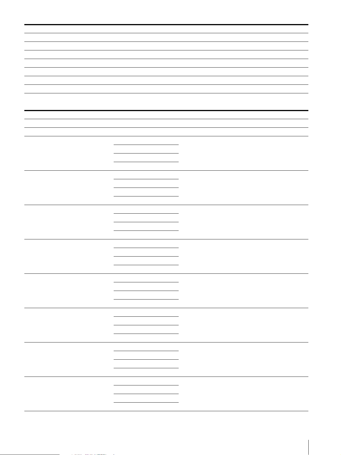
Signal System Signal Structure
1280 × 720/50P 4 : 2 : 2 (YCbCr) 10bit
1)
2048 × 1080/30
2048 × 1080/30
P 4 : 2 : 2 (YCbCr) 10bit
1)
PsF 4 : 2 : 2 (YCbCr) 10bit
2048 × 1080/25P 4 : 2 : 2 (YCbCr) 10bit
2048 × 1080/25PsF 4 : 2 : 2 (YCbCr) 10bit
1)
2048 × 1080/24
2048 × 1080/24
P 4 : 2 : 2 (YCbCr) 10bit
1)
PsF 4 : 2 : 2 (YCbCr) 10bit
2K/HD (3G-SDI)
Signal System Signal Structure
1)
1920 × 1080/60
1920 × 1080/50P 4 : 2 : 2 (YCbCr) 10bit Level A/Level B-DL
1920 × 1080/60
1920 × 1080/50I
1920 × 1080/30
1920 × 1080/30
1920 × 1080/25P
1920 × 1080/25PsF
1920 × 1080/24
1920 × 1080/24
P 4 : 2 : 2 (YCbCr) 10bit Level A/Level B-DL
4 : 4 : 4 (RGB) 10bit
1)
I
4 : 4 : 4 (YCbCr) 10bit
4 : 4 : 4 (RGB) 12bit
Level A/Level B-DL
4 : 4 : 4 (YCbCr) 12bit
4 : 4 : 4 (RGB) 10bit
4 : 4 : 4 (YCbCr) 10bit
4 : 4 : 4 (RGB) 12bit
Level A/Level B-DL
4 : 4 : 4 (YCbCr) 12bit
4 : 4 : 4 (RGB) 10bit
1)
P
4 : 4 : 4 (YCbCr) 10bit
4 : 4 : 4 (RGB) 12bit
Level A/Level B-DL
4 : 4 : 4 (YCbCr) 12bit
4 : 4 : 4 (RGB) 10bit
1)
PsF
4 : 4 : 4 (YCbCr) 10bit
4 : 4 : 4 (RGB) 12bit
Level A/Level B-DL
4 : 4 : 4 (YCbCr) 12bit
4 : 4 : 4 (RGB) 10bit
4 : 4 : 4 (YCbCr) 10bit
4 : 4 : 4 (RGB) 12bit
Level A/Level B-DL
4 : 4 : 4 (YCbCr) 12bit
4 : 4 : 4 (RGB) 10bit
4 : 4 : 4 (YCbCr) 10bit
4 : 4 : 4 (RGB) 12bit
Level A/Level B-DL
4 : 4 : 4 (YCbCr) 12bit
4 : 4 : 4 (RGB) 10bit
1)
P
4 : 4 : 4 (YCbCr) 10bit
4 : 4 : 4 (RGB) 12bit
Level A/Level B-DL
4 : 4 : 4 (YCbCr) 12bit
4 : 4 : 4 (RGB) 10bit
1)
PsF
4 : 4 : 4 (YCbCr) 10bit
4 : 4 : 4 (RGB) 12bit
Level A/Level B-DL
4 : 4 : 4 (YCbCr) 12bit
Specifications
27
Page 28
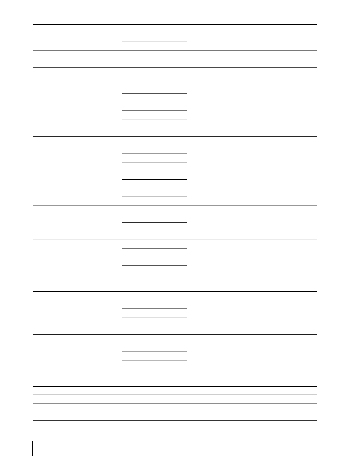
Signal System Signal Structure
1280 × 720/60 1) P
1280 × 720/50P
4 : 4 : 4 (RGB) 10bit
4 : 4 : 4 (YCbCr) 10bit
4 : 4 : 4 (RGB) 10bit
4 : 4 : 4 (YCbCr) 10bit
4 : 4 : 4 (RGB) 10bit
2048 × 1080/30
1)
P
4 : 4 : 4 (YCbCr) 10bit
4 : 4 : 4 (RGB) 12bit
4 : 4 : 4 (YCbCr) 12bit
4 : 4 : 4 (RGB) 10bit
2048 × 1080/30
1)
PsF
4 : 4 : 4 (YCbCr) 10bit
4 : 4 : 4 (RGB) 12bit
4 : 4 : 4 (YCbCr) 12bit
4 : 4 : 4 (RGB) 10bit
2048 × 1080/25P
4 : 4 : 4 (YCbCr) 10bit
4 : 4 : 4 (RGB) 12bit
4 : 4 : 4 (YCbCr) 12bit
4 : 4 : 4 (RGB) 10bit
2048 × 1080/25PsF
4 : 4 : 4 (YCbCr) 10bit
4 : 4 : 4 (RGB) 12bit
4 : 4 : 4 (YCbCr) 12bit
4 : 4 : 4 (RGB) 10bit
2048 × 1080/24
1)
P
4 : 4 : 4 (YCbCr) 10bit
4 : 4 : 4 (RGB) 12bit
4 : 4 : 4 (YCbCr) 12bit
4 : 4 : 4 (RGB) 10bit
2048 × 1080/24
1)
PsF
4 : 4 : 4 (YCbCr) 10bit
4 : 4 : 4 (RGB) 12bit
4 : 4 : 4 (YCbCr) 12bit
Level-A
Level-A
Level A/Level B-DL
Level A/Level B-DL
Level A/Level B-DL
Level A/Level B-DL
Level A/Level B-DL
Level A/Level B-DL
2K/HD (3G-SDI Dual Link)
Signal System Signal Structure
4 : 4 : 4 (RGB) 10bit
1920 × 1080/60 1) P
4 : 4 : 4 (YCbCr) 10bit
4 : 4 : 4 (RGB) 12bit
Level A/Level B-DL
4 : 4 : 4 (YCbCr) 12bit
4 : 4 : 4 (RGB) 10bit
1920 × 1080/50P
4 : 4 : 4 (YCbCr) 10bit
4 : 4 : 4 (RGB) 12bit
Level A/Level B-DL
4 : 4 : 4 (YCbCr) 12bit
4K/UHD (HD-SDI Quad Link)
Signal System Signal Structure
1)
3840 × 2160/30
3840 × 2160/30
3840 × 2160/25P 4 : 2 : 2 (YCbCr) 10bit Square
28
Specifications
P 4 : 2 : 2 (YCbCr) 10bit Square
1)
PsF 4 : 2 : 2 (YCbCr) 10bit Square
Page 29
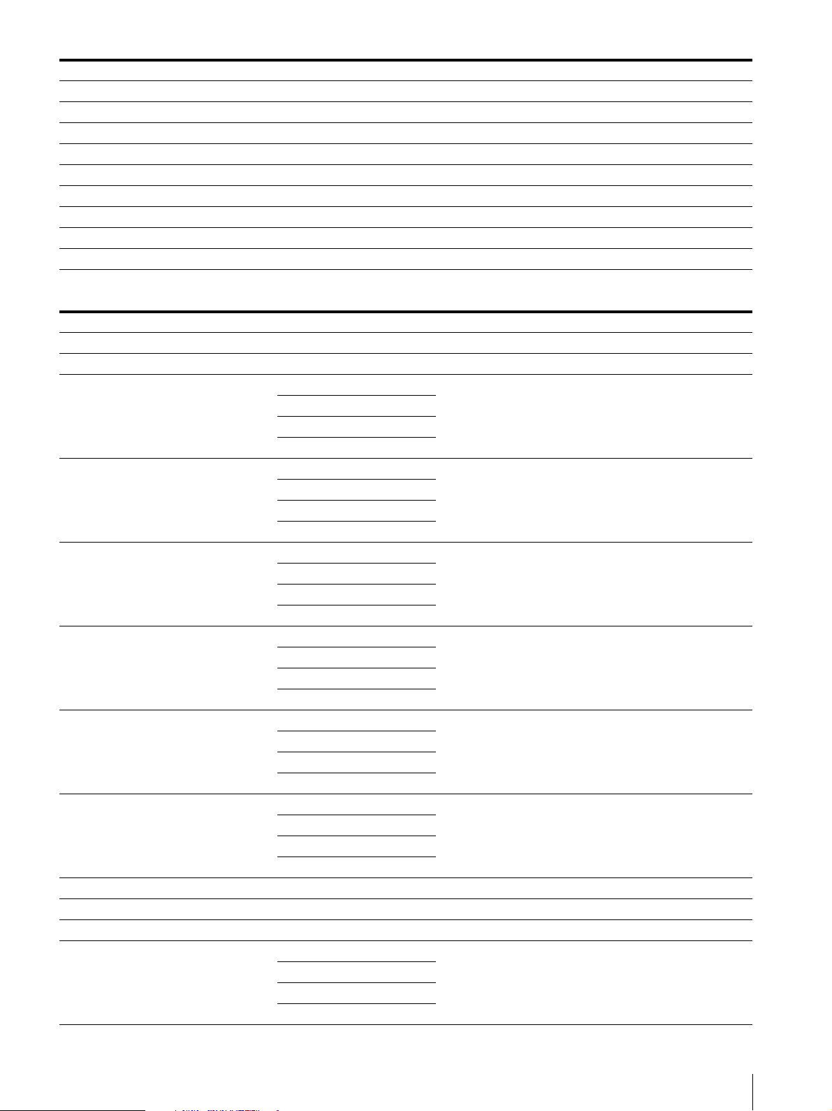
Signal System Signal Structure
3840 × 2160/25PsF 4 : 2 : 2 (YCbCr) 10bit Square
1)
3840 × 2160/24
3840 × 2160/24
4096 × 2160/30
4096 × 2160/30
P 4 : 2 : 2 (YCbCr) 10bit Square
1)
PsF 4 : 2 : 2 (YCbCr) 10bit Square
1)
P 4 : 2 : 2 (YCbCr) 10bit Square
1)
PsF 4 : 2 : 2 (YCbCr) 10bit Square
4096 × 2160/25P 4 : 2 : 2 (YCbCr) 10bit Square
4096 × 2160/25PsF 4 : 2 : 2 (YCbCr) 10bit Square
1)
4096 × 2160/24
4096 × 2160/24
P 4 : 2 : 2 (YCbCr) 10bit Square
1)
PsF 4 : 2 : 2 (YCbCr) 10bit Square
4K/UHD (3G-SDI Quad Link)
Signal System Signal Structure
1)
3840 × 2160/60
3840 × 2160/50P 4 : 2 : 2 (YCbCr) 10bit Level A/Level B-DL Square/2SI
3840 × 2160/30
3840 × 2160/30
3840 × 2160/25P
3840 × 2160/25PsF
3840 × 2160/24
3840 × 2160/24
4096 × 2160/60
4096 × 2160/50P 4 : 2 : 2 (YCbCr) 10bit Level A/Level B-DL Square/2SI
4096 × 2160/48
4096 × 2160/30 1) P
P 4 : 2 : 2 (YCbCr) 10bit Level A/Level B-DL Square/2SI
4 : 4 : 4 (RGB) 10bit
1)
P
4 : 4 : 4 (YCbCr) 10bit
4 : 4 : 4 (RGB) 12bit
Level A/Level B-DL Square/2SI
4 : 4 : 4 (YCbCr) 12bit
4 : 4 : 4 (RGB) 10bit
1)
PsF
4 : 4 : 4 (YCbCr) 10bit
4 : 4 : 4 (RGB) 12bit
Level A/Level B-DL Square
4 : 4 : 4 (YCbCr) 12bit
4 : 4 : 4 (RGB) 10bit
4 : 4 : 4 (YCbCr) 10bit
4 : 4 : 4 (RGB) 12bit
Level A/Level B-DL Square/2SI
4 : 4 : 4 (YCbCr) 12bit
4 : 4 : 4 (RGB) 10bit
4 : 4 : 4 (YCbCr) 10bit
4 : 4 : 4 (RGB) 12bit
Level A/Level B-DL Square
4 : 4 : 4 (YCbCr) 12bit
4 : 4 : 4 (RGB) 10bit
1)
P
4 : 4 : 4 (YCbCr) 10bit
4 : 4 : 4 (RGB) 12bit
Level A/Level B-DL Square/2SI
4 : 4 : 4 (YCbCr) 12bit
4 : 4 : 4 (RGB) 10bit
1)
PsF
4 : 4 : 4 (YCbCr) 10bit
4 : 4 : 4 (RGB) 12bit
Level A/Level B-DL Square
4 : 4 : 4 (YCbCr) 12bit
1)
P 4 : 2 : 2 (YCbCr) 10bit Level A/Level B-DL Square/2SI
1)
P 4 : 2 : 2 (YCbCr) 10bit Level A/Level B-DL Square/2SI
4 : 4 : 4 (RGB) 10bit
4 : 4 : 4 (YCbCr) 10bit
4 : 4 : 4 (RGB) 12bit
Level A/Level B-DL Square/2SI
4 : 4 : 4 (YCbCr) 12bit
Specifications
29
Page 30
Signal System Signal Structure
4 : 4 : 4 (RGB) 10bit
4096 × 2160/30 1) PsF
4 : 4 : 4 (YCbCr) 10bit
4 : 4 : 4 (RGB) 12bit
4 : 4 : 4 (YCbCr) 12bit
4 : 4 : 4 (RGB) 10bit
4096 × 2160/25P
4 : 4 : 4 (YCbCr) 10bit
4 : 4 : 4 (RGB) 12bit
4 : 4 : 4 (YCbCr) 12bit
4 : 4 : 4 (RGB) 10bit
4096 × 2160/25PsF
4 : 4 : 4 (YCbCr) 10bit
4 : 4 : 4 (RGB) 12bit
4 : 4 : 4 (YCbCr) 12bit
4 : 4 : 4 (RGB) 10bit
4096 × 2160/24
1)
P
4 : 4 : 4 (YCbCr) 10bit
4 : 4 : 4 (RGB) 12bit
4 : 4 : 4 (YCbCr) 12bit
4 : 4 : 4 (RGB) 10bit
4096 × 2160/24
1)
PsF
4 : 4 : 4 (YCbCr) 10bit
4 : 4 : 4 (RGB) 12bit
4 : 4 : 4 (YCbCr) 12bit
Level A/Level B-DL Square
Level A/Level B-DL Square/2SI
Level A/Level B-DL Square
Level A/Level B-DL Square/2SI
Level A/Level B-DL Square
1) Also compatible with 1/1.001.
30
Specifications
Page 31
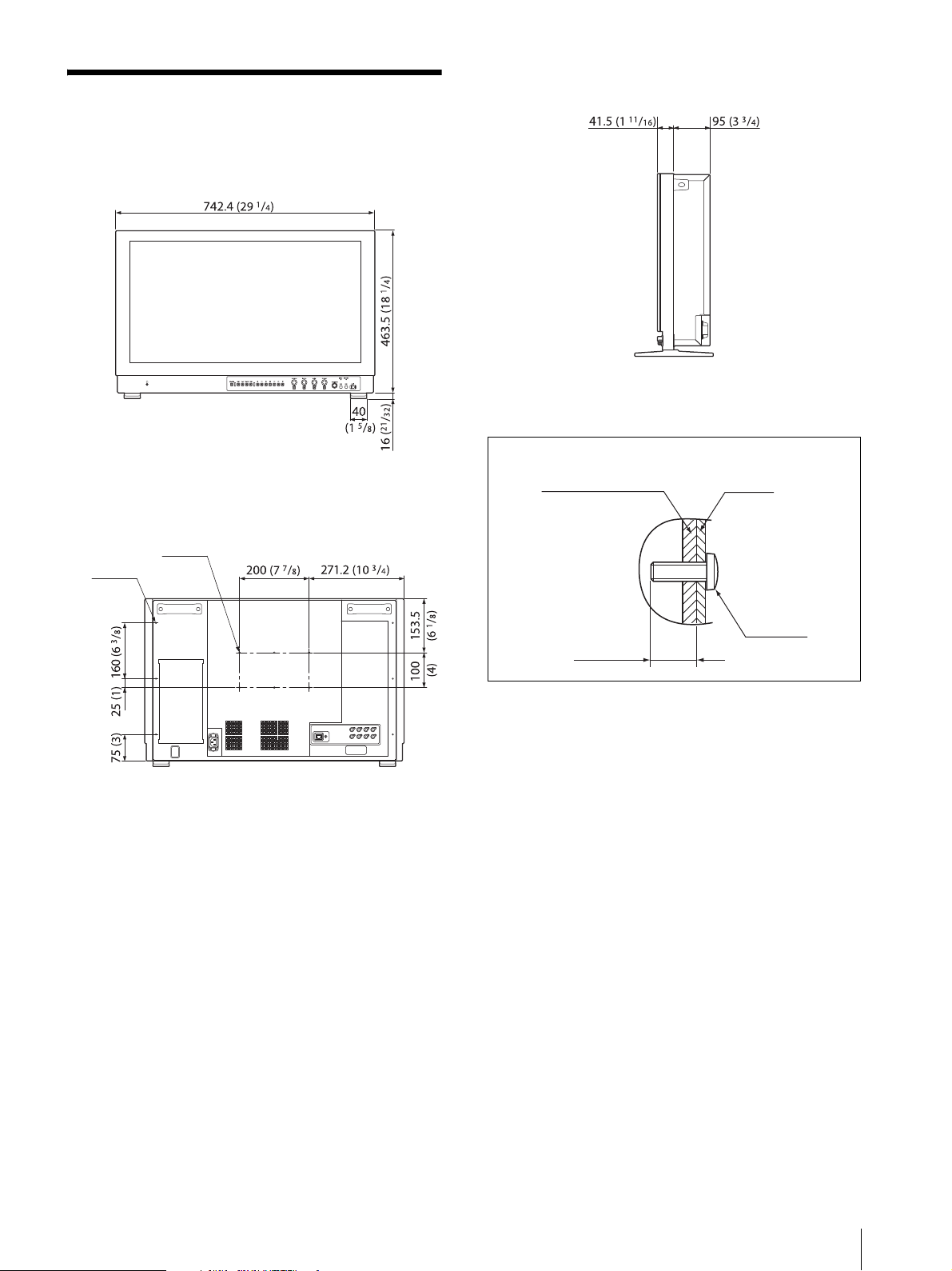
Dimensions
6-M4 hole
6-M4 hole
(for the YOKE mount)
* Length of M4 screws (rear)
Monitor cabinet
Attached object
6 (
1
/4) to 7 (9/32)
M4 screw
Front
Rear
Side
Unit: mm (inches)
Mass:
Approx. 16.0 kg (35 lb 4.4 oz)
To install on a vehicle, fix the unit using screw holes for
the YOKE mount.
Unit: mm (inches)
Dimensions
31
Page 32

Sony Corporation
 Loading...