

Page 1
PROFESSIONAL VIDEO MONITOR
BVM-E250A
BVM-E170A
OPERATION MANUAL [English]
1st Edition
Page 2
Before operating the unit, please read this manual
thoroughly and retain it for future reference.
For BVM-E250A/E170A
Important Safety Instructions
• Read these instructions.
• Keep these instructions.
• Heed all warnings.
• Follow all instructions.
• Do not use this apparatus near water.
• Clean only with dry cloth.
• Do not block any ventilation openings.
Install in accordance with the manufacturer's
instructions.
• Do not install near any heat sources such as radiators,
heat registers, stoves, or other apparatus (including
amplifiers) that produce heat.
• Do not defeat the safety purpose of the polarized or
grounding-type plug. A polarized plug has two blades
with one wider than the other. A grounding-type plug
has two blades and a third grounding prong. The wide
blade or the third prong are provided for your safety. If
the provided plug does not fit into your outlet, consult an
electrician for replacement of the obsolete outlet.
• Protect the power cord from being walked on or pinched
particularly at plugs, convenience receptacles, and the
point where they exit from the apparatus.
• Only use attachments/accessories specified by the
manufacturer.
• Use only with the cart, stand, tripod, bracket, or table
specified by the manufacturer, or sold with the
apparatus. When a cart is used, use caution when
moving the cart/apparatus combination to avoid injury
from tip-over.
WARNING
To reduce the risk of fire or electric shock, do not
expose this apparatus to rain or moisture.
To avoid electrical shock, do not open the
cabinet. Refer servicing to qualified personnel
only.
THIS APPARATUS MUST BE EARTHED.
For BVM-E250A only
This apparatus is provided with a main switch on the left
side panel.
Install this apparatus so that user can access the main
switch easily.
For BVM-E170A only
WARNING
When installing the unit, incorporate a readily accessible
disconnect device in the fixed wiring, or connect the power
plug to an easily accessible socket-outlet near the unit. If
a fault should occur during operation of the unit, operate
the disconnect device to switch the power supply off, or
disconnect the power plug.
For BVM-E250A/E170A
CAUTION
The apparatus shall not be exposed to dripping or
splashing. No objects filled with liquids, such as vases,
shall be placed on the apparatus.
CAUTION
The unit is not disconnected from the AC power source
(mains) as long as it is connected to the wall outlet, even if
the unit itself has been turned off.
• Unplug this apparatus during lightning storms or when
unused for long periods of time.
• Refer all servicing to qualified service personnel.
Servicing is required when the apparatus has been
damaged in any way, such as power-supply cord or plug
is damaged, liquid has been spilled or objects have fallen
into the apparatus, the apparatus has been exposed to
rain or moisture, does not operate normally, or has been
dropped.
2
This symbol is intended to alert the user to
the presence of uninsulated “dangerous
voltage” within the product’s enclosure that
may be of sufficient magnitude to constitute
a risk of electric shock to persons.
Page 3
This symbol is intended to alert the user to
the presence of important operating and
maintenance (servicing) instructions in the
literature accompanying the appliance.
conforms to the safety regulations of each country if
applicable.
2. Use the Power Cord (3-core mains lead) / Appliance
Connector / Plug conforming to the proper ratings
(Voltage, Ampere).
For the customers in the U.S.A.
This equipment has been tested and found to comply with
the limits for a Class A digital device, pursuant to Part 15
of the FCC Rules. These limits are designed to provide
reasonable protection against harmful interference when
the equipment is operated in a commercial environment.
This equipment generates, uses, and can radiate radio
frequency energy and, if not installed and used in
accordance with the instruction manual, may cause
harmful interference to radio communications. Operation
of this equipment in a residential area is likely to cause
harmful interference in which case the user will be
required to correct the interference at his own expense.
You are cautioned that any changes or modifications not
expressly approved in this manual could void your
authority to operate this equipment.
All interface cables used to connect peripherals must be
shielded in order to comply with the limits for a digital
device pursuant to Subpart B of Part 15 of FCC Rules.
This device complies with Part 15 of the FCC Rules.
Operation is subject to the following two conditions: (1)
this device may not cause harmful interference, and (2) this
device must accept any interference received, including
interference that may cause undesired operation.
If you have questions on the use of the above Power Cord
/ Appliance Connector / Plug, please consult a qualified
service personnel.
For the customers in Canada
This Class A digital apparatus complies with Canadian
ICES-003.
For the customers in Europe
This product with the CE marking complies with the EMC
Directive issued by the Commission of the European
Community.
Compliance with this directive implies conformity to the
following European standards:
• EN55103-1 : Electromagnetic Interference (Emission)
• EN55103-2 : Electromagnetic Susceptibility (Immunity)
This product is intended for use in the following
Electromagnetic Environment: E4 (controlled EMC
environment, ex. TV studio).
This product has been manufactured by or on behalf of
Sony Corporation, 1-7-1 Konan Minato-ku Tokyo, 1080075 Japan. Inquiries related to product compliance based
on European Union legislation shall be addressed to the
authorized representative, Sony Deutschland GmbH,
Hedelfinger Strasse 61, 70327 Stuttgart, Germany. For any
service or guarantee matters, please refer to the addresses
provided in the separate service or guarantee documents.
WARNING: THIS WARNING IS APPLICABLE FOR
USA ONLY.
If used in USA, use the UL LISTED power cord specified
below.
DO NOT USE ANY OTHER POWER CORD.
Plug Cap Parallel blade with ground pin
(NEMA 5-15P Configuration)
Cord Type SJT or SVT, three 16 or 18 AWG wires
Length Minimum 1.5 m (4 ft .11in.), Less than 2.5 m
(8 ft .3 in.)
Rating Minimum 10A, 125V
Using this unit at a voltage other than 120V may require
the use of a different line cord or attachment plug, or both.
To reduce the risk of fire or electric shock, refer servicing
to qualified service personnel.
WARNING: THIS WARNING IS APPLICABLE FOR
OTHER COUNTRIES.
1. Use the approved Power Cord (3-core mains lead) /
Appliance Connector / Plug with earthing-contacts that
This apparatus shall not be used in the residential area.
For BVM-E170A only
Attention-when the product is installed in Rack:
1.
Prevention against overloading of branch circuit
When this product is installed in a rack and is supplied
power from an outlet on the rack, please make sure that the
rack does not overload the supply circuit.
2.Providing protective earth
When this product is installed in a rack and is supplied
power from an outlet on the rack, please confirm that the
outlet is provided with a suitable protective earth
connection.
3.Internal air ambient temperature of the rack
When this product is installed in a rack, please make sure
that the internal air ambient temperature of the rack is
within the specified limit of this product.
3
Page 4

4.Prevention against achieving hazardous
condition due to uneven mechanical loading
When this product is installed in a rack, please make sure
that the rack does not achieve hazardous condition due to
uneven mechanical loading.
5.Install the equipment while taking the operating
temperature of the equipment into consideration
For the operating temperature of the equipment, refer to
the specifications of the Operation Manual.
6.When performing the installation, keep the
following space away from walls in order to
obtain proper exhaust and radiation of heat.
Lower, Upper: 4.4 cm (1
Right, Left: 1.0 cm (
3
/4 inches) or more
13
/32 inches) or more
For BVM-E250A/E170A
For the customers in Europe, Australia and New
Zealand
WARNING
This is a Class A product. In a domestic environment, this
product may cause radio interference in which case the
user may be required to take adequate measures.
For kundene i Norge
Dette utstyret kan kobles til et IT-strømfordelingssystem.
Apparatet må tilkoples jordet stikkontakt
Suomessa asuville asiakkaille
Laite on liitettävä suojamaadoituskoskettimilla
varustettuun pistorasiaan
För kunderna i Sverige
Apparaten skall anslutas till jordat uttag
4
Page 5
Table of Contents
Chapter 1 Overview
Precautions ........................................................7
On Safety .............................................................7
On Installation......................................................7
Handling the Screen.............................................7
On Burn-in ...........................................................7
On a Long Period of Use .....................................8
Handling and Maintenance of the Screen ............8
On Dew Condensation .........................................8
On Repacking.......................................................8
Disposal of the Unit .............................................8
On Fan Error ........................................................8
Features..............................................................9
Options ............................................................. 12
Input/Output Connectors and Input
Adaptors ............................................. 13
Location and Function of Parts
(BVM-E250A) ......................................14
Front Panel .........................................................14
Rear Panel/Left Side Panel ................................16
Location and Function of Parts
(BVM-E170A) ......................................18
Front Panel .........................................................18
Rear Panel ..........................................................20
Chapter 2 Preparations
Environments of the Installation Location ....22
Input Adaptors ................................................. 22
Version of the Controller................................. 23
Installing an Input Adaptor (BVM-E250A)......23
Installing an Input Adaptor (BVM-E170A)......25
Preventing Falling of the Monitor
(BVM-E250A) ......................................26
Mounting the Unit in a Rack (BVM-E170A) .... 27
Connections (BVM-E250A)..............................27
Connecting the Controller (BKM-16R)............. 28
Connecting the Multiple Units with the
LAN...................................................28
Connections (BVM-E170A)..............................29
Connecting the Controller (BKM-16R)............. 30
Connecting the Multiple Units with the
LAN...................................................30
Turning on the Power (BVM-E250A) ..............31
Connecting the AC Power Cord ........................31
Turning on the Monitor......................................31
Turning on the Power (BVM-E170A) .............. 32
Connecting to Power..........................................32
Turning on the Monitor......................................33
Settings ............................................................ 33
Selecting the Area ..............................................33
Setting for the LAN to Connect the Multiple
Units ..................................................35
Selecting the Monitor (Designation of the Monitor
or Group ID Number)........................36
Assigning the Input Signal to the Channel.........37
Setting the Display Mode of the Picture............37
Adjusting .......................................................... 37
Chroma/Phase Adjustment.................................37
Color Temperature (White Balance)
Adjustment ........................................38
Brightness/Contrast Adjustment........................39
Chapter 3 Menu
Basic Menu Operations................................... 40
Menu Operation Buttons....................................40
Displaying the Menu..........................................41
Setting or Adjusting in the Menu Operation ......41
Entering the Channel Number............................43
Aborting Menu Operation..................................43
Menu Structure ................................................ 44
Adjustment Menu ............................................ 51
Overview............................................................51
Menu Function and Operation ...........................51
Channel Configuration Menu ......................... 58
Overview............................................................58
Menu Function and Operation ...........................58
Auxiliary Setting Menu .................................... 67
Overview............................................................67
Menu Function and Operation ...........................67
Function Setting Menu.................................... 69
Overview............................................................69
Menu Function and Operation ...........................69
System Configuration Menu ........................... 81
Overview............................................................81
Menu Function and Operation ...........................81
File Management Menu ................................... 87
Overview............................................................87
Menu Function and Operation ...........................87
System Status Menu ....................................... 89
Overview............................................................89
Menu Function and Operation ...........................89
Controller Menu ............................................... 91
Table of Contents
5
Page 6
Overview ............................................................91
Menu Function and Operation ...........................91
Key Protect Menu ............................................ 96
Overview ............................................................96
Menu Function and Operation ...........................96
Chapter 4 Operations
Selecting Display Mode .................................. 97
Setting the Display of Native Scan Mode ...... 98
Selecting the Native Scan/Scan Mode........... 99
Displaying Two Signals on One Screen
(Picture&Picture) ............................. 100
Magnifying the Picture (Pixel Zoom) ........... 101
Capturing the Picture of the HD Signal
(HD Frame Capture)......................... 102
Displaying the Area Marker or Aspect
Marker ............................................... 103
Displaying the Audio Level Meter ................ 104
Displaying the Time Code............................. 105
Switching the Display of the 3D Video
Signal................................................ 106
Copying the Setting or Adjustment Value to
Another Monitor............................... 107
Displaying the Monitor Status Page ............ 108
Assigning a Function to a Function
Button ............................................... 110
Assigning a Function to a Function Button......110
Displaying the Assigned Functions
Collectively......................................110
Upgrading the Monitor and Controller ........ 111
Saving the Upgrade Data in a “Memory Stick
PRO”................................................111
Upgrading the Monitor.....................................112
Upgrading the Controller .................................113
Inserting/Ejecting the “Memory Stick”.........146
Notes on “Memory Stick”................................146
Menu Index 148
Appendixes
Specifications (BVM-E250A)......................... 115
Specifications (BVM-E170A)......................... 117
Input Signals and Adjustable/Setting
Items ................................................. 120
Available Signal Systems ............................. 122
Available Signal Formats.............................. 124
Aperture Modification Frequency ................ 132
Picture Display Size ...................................... 134
Picture Frame Display ................................... 136
Scan Mode Image .......................................... 138
Troubleshooting ............................................ 140
Dimensions (BVM-E250A)............................. 142
Dimensions (BVM-E170A)............................. 144
6
Table of Contents
Using This Manual
This Operation Manual includes explanations for the
BVM-E250A and BVM-E170A.
The model name is specified where there is a difference
between the two models. (Example: Location and
Function of Parts (BVM-E250A))
Please note that the explanations are common to both
models where no model name is specified.
Page 7
Chapter 1 Overview
Overview
Precautions
On Safety
• Operate the unit only with a power source as specified
in the “Specifications” section.
• A nameplate indicating operating voltage, power
consumption, etc., is located on the rear panel.
• Should any solid object or liquid fall into the cabinet,
unplug the unit and have it checked by qualified
personnel before operating it any further.
• Do not drop or place heavy objects on the power cord.
If the power cord is damaged, turn off the power
immediately. It is dangerous to use the unit with a
damaged power cord.
• Unplug the unit from the wall outlet if it is not to be used
for several days or more.
• Disconnect the power cord from the AC outlet by
grasping the plug, not by pulling the cord.
• The socket-outlet shall be installed near the equipment
and shall be easily accessible.
On Installation
Chapter
• Leave more than 40 cm of space in the rear of the unit
to secure the operation area.
When the unit is installed on the desk or the like, leave at
least 1U (4.4 cm) or more of space above and below the
unit. Leaving 40 cm or more of space above the unit is
recommended for service operation.
1
Handling the Screen
• The OLED panel fitted to this unit is manufactured with
high precision technology, giving a functioning pixel
ratio of at least 99.99%. Thus a very small proportion of
pixels may be “stuck”, either always off (black), always
on (red, green, or blue), or flashing. In addition, over a
long period of use, because of the physical
characteristics of the panel, such “stuck” pixels may
appear spontaneously. These problems are not a
malfunction.
• Do not leave the screen facing the sun as it can damage
the screen. Take care when you place the unit by a
window.
• Do not push or scratch the monitor’s screen. Do not
place a heavy object on the monitor’s screen. This may
cause the screen to lose uniformity.
• The screen and the cabinet become warm during
operation. This is not a malfunction.
• Allow adequate air circulation to prevent internal heat
build-up.
Do not place the unit on surfaces (rugs, blankets, etc.) or
near materials (curtains, draperies) that may block the
ventilation holes.
• Do not install the unit in a location near heat sources
such as radiators or air ducts, or in a place subject to
direct sunlight, excessive dust, mechanical vibration or
shock.
For BVM-E250A only
When installing the installation space must be secured in
consideration of the ventilation and service operation.
• Do not block the ventilation slots, and vents of the fans.
• Leave a space around the unit for ventilation.
On Burn-in
Due to the characteristics of the material used in the
OLED panel, permanent burn-in or reduction in
brightness may occur.
These problems are not a malfunction.
Images that may cause burn-in
• Masked images with aspect ratios other than 16:9
• Color bars or images that remain static for a long time
• Character or message displays that indicate settings or
the operating state
• On-screen displays such as center markers or area
markers
Precautions
7
Page 8
To reduce the risk of burn-in
• Turn off the character and marker displays
Press the MENU button to turn off the character displays.
To turn off the character or marker displays of the
connected equipment, operate the connected equipment
accordingly. For details, refer to the operation manual of
Chapter 1 Overview
the connected equipment.
• Turn off the power when not in use
Turn off the power if the monitor is not to be used for a
prolonged period of time.
Screen saver
This product has a built-in screen saver function to reduce
burn-in. When an almost still image is displayed for more
than 10 minutes, the screen saver starts automatically and
the brightness of the screen decreases.
On a Long Period of Use
Due to an OLED’s panel structure and characteristics of
materials in its design, displaying static images for
extended periods, or using the unit repeatedly in a high
temperature/high humidity environments may cause image
smearing, burn-in, areas of which brightness is
permanently changed, lines, or a decrease in overall
brightness.
• Wipe the screen surface gently with the supplied
cleaning cloth or a soft dry cloth to remove dirt.
• Stubborn stains may be removed with the supplied
cleaning cloth, or a soft cloth slightly dampened with a
mild detergent solution.
• The screen may become scratched if the cleaning cloth is
dusty.
• Never use strong solvents such as alcohol, benzene,
thinner, acidic or alkaline detergent, detergent with
abrasives, or chemical wipe as these may damage the
screen.
• Use a blower to remove dust from the screen surface.
On Dew Condensation
If the unit is suddenly taken from a cold to a warm location,
or if ambient temperature suddenly rises, moisture may
form on the outer surface of the unit and/or inside of the
unit. This is known as condensation. If condensation
occurs, turn off the unit and wait until the condensation
clears before operating the unit. Operating the unit while
condensation is present may damage the unit.
On Repacking
In particular, continued display of an image smaller than
the monitor screen, such as in a different aspect ratio, may
shorten the life of the unit.
Avoid displaying a still image for an extended period, or
using the unit repeatedly in a high temperature/high
humidity environment such an airtight room, or around the
outlet of an air conditioner.
To prevent any of the above issues, we recommend
reducing brightness slightly, and to turn off the power
whenever the unit is not in use.
Handling and Maintenance of the Screen
The surface of the screen is specially coated to reduce
image reflection. Make sure to observe the following
points as improper maintenance procedures may impair the
screen’s performance. In addition, the screen is vulnerable
to damage. Do not scratch or knock against it using a hard
object.
• Be sure to disconnect the AC power cord from the AC
outlet before performing maintenance.
• The surface of the screen is specially coated. Do not
attach adhesive objects, such as stickers, on it.
• The surface of the screen is specially coated. Do not
touch the screen directly.
Do not throw away the carton and packing materials. They
make an ideal container which to transport the unit.
Disposal of the Unit
Do not dispose of the unit with general waste.
Do not include the monitor with household waste.
When you dispose of the monitor, you must obey the law
in the relative area or country.
On Fan Error
The fan for cooling the unit is built in. When the fan stops
and the OPERATE lamp flashes in red, the OVER RANGE
lamp flashes in amber, and the ECO lamp lights in magenta
on the front panel for fan error indication, turn off the
power and contact an authorized Sony dealer.
If you have any questions about this unit, please contact
your Sony service representative.
8
Precautions
Page 9
Features
The BVM-E250A is 25-inch Professional Video Monitor,
and the BVM-E170A is 16.5-inch Professional Video
Monitor.
These are suitable for television stations or video
production houses, where precise image reproduction is
required.
The monitor features OLED panel and “TRIMASTER
which is a new technology developed for three elements,
“accurate color reproduction”, “precision imaging” and
“quality picture consistency,” that are in demand for
professional use. “TRIMASTER” decreases the viewing
difference that occurs due to the individuality of each
panel. Also, the monitor realizes the high picture quality
and high-trust required for the master monitor by the color
management system with its wide color gamut device,
high-resolution/precise gradation display, highly accurate
signal processing and panel correction function.
1) TRIMASTER is a trademark of Sony Corporation.
Advantages of OLED panel technology
The OLED panel makes use of an organic material, which
emits light when an electric current is applied. Being selfemitting, the strength of luminescence can be controlled by
the amount of electric current. This brings about the
following three features:
Quick motion picture response:
The luminescent state of the OLED panel can be changed
instantaneously by changing the current flow in the organic
material. This enables a quick motion picture response and
production of images with minimal blurring and ghosting.
Furthermore, performance for shooting on location is not
influenced by changes in environmental temperature.
1)
”,
emission structure of TFT, Sony’s OLED panel can
reproduce a crisper image due to high brightness.
Furthermore, a unique microcavity structure makes RGB
primary colors purer and deeper by utilizing light
resonance effects that magnify optimum light wave lengths
and diminish undesired light wave lengths.
The panel’s 10-bit driver enables smooth gradation of color
shading.
2) “Super Top Emission” is a trademark that represents the OLED
technology of Sony Corporation.
12-bit precision display engine for professional
use
The panel is equipped with a unique signal process engine
developed for the professional use monitor. This engine
incorporates 12-bit output accuracy at each process, and
provides a high-quality I/P conversion algorithm, scaling
processing, panel driving and a highly accurate color
management system.
Multi color space
The Sony’s unique OLED panel with a wide color gamut
and color management system which uses the unique 3D
LUT (Look Up Table) reproduces the color space that
complies with the broadcast standard ITU-R BT.709, EBU
and SMPTE-C accurately. A wider color space
3)
allows
digital cinema reproductions.
3) The RGB chromaticity of SMPTE RP 431-2 is not covered in full.
High-quality I/P conversion processing
A high-quality picture near the original one, in which
jagged lines and conversion errors are decreased by
detecting the feature of the picture inside the subdivided
block and processing properly, is reproduced.
The signal delay is decreased by judging the animation or
still picture from the past video signal. Film cadence
processing, which converts the signal composed of 2-2·23·2-3-3-2 pull down to the I/P signal closely following the
original, is also selectable.
Chapter 1 Overview
High contrast and wide dynamic range:
The OLED panel does not emit light when black signal is
applied to the monitor, enabling a pure black screen to be
displayed. Furthermore, thanks to a wide dynamic range
the panel impressively displays brilliance and clarity of
various sparkling images, such as stars in a night sky
twinkling, night illuminations winking or glass glittering,
etc.
Rich color reproduction:
An OLED panel’s self-luminescence also allows for great
color reproduction across the entire spectrum in practically
any shade or brightness.
Sony’s Super Top Emission
2)
OLED panel
The 25-type (BVM-E250A) or 16.5-type (BVM-E170A)
full HD (1920 × 1080) OLED panel features Sony’s Super
Top Emission structure. Unlike the conventional bottom
Interlace display mode
The interlace signal is displayed as the interlace picture by
inserting the black line without I/P conversion processing.
A picture faithful to the original signal and with the same
feel as a CRT is gained.
For setting the display, see “Selecting Display Mode” on
page 97.
Available to a multi signal format
The monitor supports various input signals such as 720 ×
576/50i to 1920 × 1080/50P, 60P, digital cinema (D-Cine)
2048 × 1080/24P and variable computer signals up to
1920 × 1080. The 3G/HD/SD-SDI inputs, HDMI
DisplayPort
5)
(HDCP correspondence) inputs, and four
4)
and
option ports are equipped for the standard interface. If you
install optional input adaptors, the monitor expands inputs
of 3G-SDI, HD-SDI or SD-SDI, and supports Dual-link
HD-SDI, RGB, YPbPr, Y/C, and composite signal inputs.
Features
9
Page 10
4) The terms HDMI and HDMI High-Definition Multimedia Interface, and
the HDMI Logo are trademarks or registered trademarks of HDMI
Licensing LLC in the United States and other countries.
5) DisplayPort, DisplayPort logo and VESA are trademarks or registered
trademarks of Video Electronics Standards Association.
HD frame capture function
Chapter 1 Overview
The frame of the 3G/HD-SDI input signal is captured and
6)
saved
as a picture file in the “Memory Stick”. This is
used to confirm the color tone and picture angle of the
current scene and recorded scene by using the multi display
(Picture&Picture) function.
For the operation, see “Capturing the Picture of the HD
Signal (HD Frame Capture)” on page 102.
6) As the frame of the input signal is captured, the data and marker set by the
monitor is not reflected.
Multi display function
Two kinds of input signals are output on the monitor. You
can select from side by side, wipe, butterfly and blending
mode. This is useful for adjusting the color or comparing
two pictures.
For the operation, see “Displaying Two Signals on One
Screen (Picture&Picture)” on page 100.
Pixel zoom function
As part of the picture is magnified up to 8 times without
scaling processing, this is convenient for confirming a
minute part of the signal.
For the operation, see “Magnifying the Picture (Pixel
Zoom)” on page 101.
Safe area marker and aspect marker functions
The monitor is equipped with two area markers and center
marker as the safe area marker and aspect marker for
confirming the picture angle.
For the operation, see “Displaying the Area Marker or
Aspect Marker” on page 103.
Scan selection/Native scan display function
You can select from under scan (–3%), normal scan (0%)
and over scan (mask of the 5% over scan portion in the
normal scan) for the picture display.
The monitor is equipped with a native scan display
function which maps the pixel of the signal to the panel in
one-to-one mode. You can select the mode from ×1, ×2 or
Aspect Correction to display a signal in native mode. An
SD signal of non-square pixels (the number of H pixels of
the signal system is 720 or 1440) or a 640 × 480 SD signal
of HDMI/DisplayPort video is displayed correctly by
scaling processing of doubling for the V direction and
correct aspect ratio for the H direction, and the picture is
also optimized and displayed by modifying the aperture
coefficient value, filter coefficient value, etc. in Aspect
Correction mode.
For the operation, see “Selecting the Native Scan/Scan
Mode” on page 99.
Gamut error function
The signal outside the specified range (gamut error) caused
by the conversion of the format or during CG/CM
production is displayed in a zebra pattern.
Aspect selectable function
A squeezed and recorded signal is displayed with the
correct angle. You can select from 4:3, 16:9, 1.896:1 and
7)
2.39:1
7) When the aspect ratio is set to 2.39:1, the resolution is reduced.
aspect modes.
Remote control function (Ethernet control)
The controller controls up to 32 monitors by the Ethernet
(10BASE-T/100BASE-TX) connection. Up to four
controllers are connected to one monitor in single mode.
You can control individual monitors or monitor groups
simply by entering the monitor ID number or group ID
number. You can also execute the same operation on all
connected monitors, or put all connected monitors into the
same setup and adjustment state.
Time code display function
The time code superimposed on the SDI signal is
displayed.
Closed caption display function
EIA/CEA-608 or EIA/CEA-708 standard closed caption
signals superimposed on the SDI signals are displayed by
installing the optional input adaptor (BKM-244CC).
Audio level meter display function
The audio level of the embedded audio signals
superimposed on the SDI signal is displayed by installing
the optional input adaptor (BKM-250TG).
3D signal analyzing function
The monitor supports the following display modes of the
3D signal analyzing function if you install the optional
input adaptor (BKM-250TG). For this function, twodimensional (2D) view is used. The signals are not
displayed in stereoscopic view.
The available display modes differ depending on the serial
number of the BKM-250TG.
For the operation, see “Switching the Display of the 3D
Video Signal” on page 106.
Difference display (with serial number 7300001 or
higher):
The difference between the luminance signal of the left (L)
3D video signal and that of the right (R) signal is displayed.
This display is useful for checking parallax amount.
Checkerboard display (with serial number 7100001 or
higher):
10
Features
Page 11
The left (L) and right (R) 3D video signals are displayed in
a checkerboard pattern on the screen. This display is useful
for comparing the luminance or color settings of
neighboring L and R images.
L/R switching display (with serial number 7100001 or
higher):
The dual-stream left (L) and right (R) 3D video signals are
alternately displayed on the screen. This display is useful
for comparing the color or brightness of the L and R
signals, as a black frame is not inserted when the two
signals are switched.
Horopter check display (with serial number 7100001 or
higher):
Either left (L) or right (R) 3D video signals, or both L and
R signals are displayed in monochrome mode. This display
is useful for checking a subtle depth of a subject located in
the boundary plane of the screen, that is, whether it is near
or far from the screen surface.
Horizontal flip display (with serial number 7100001 or
higher):
The input 3D video signals whose left (L) or right (R)
signal has been inverted horizontally by a half-mirror type
3D rig are displayed as non-inverted images.
Other features
• The color temperature is selectable from D65, D93, D61,
D55, D-Cine and User.
• Built-in test pattern for 100% white signal, 20% gray
signal, 0% black signal, PLUGE (Picture Line Up
Generation Equipment) signal, color-bar signal, 5 step
gray scale signal and ramp signal.
• Chroma Up function that increases the chroma setting by
12 dB.
• Blue only function and RGB cut off function to monitor
signal noise.
• A parallel remote of the contact point control connector
is equipped.
Chapter 1 Overview
Note
The horizontal flip display function of this monitor inverts
the input signals to display them. Since the internal sync is
applied to any signal delayed by the inversion, there is a
time lag between input and the displayed image.
Screen saver
When a nearly still image is displayed continuously for 10
minutes or more, the screen saver starts automatically to
reduce the brightness of the screen to prevent burn-in.
Variable picture adjustment functions
Auto chroma, phase and matrix adjustment functions are
equipped.
ASC CDL and User LUT functions
The ASC CDL (American Society of Cinematographers
Color Decision List) function and the User LUT (User
Look-up Table) function allow you to change color
representation of the monitor during production of digital
cinemas, recorded television shows, and commercials.
You can view the camera images being shot on the set, with
the color representation applied, using the ASC CDL
function. You can also reproduce a pseudo image that is
printed on film, using the User LUT function.
These functions facilitate the decision process of creative
color representation or improve the workflow between onlocation and post-production work.
These functions require special third-party software. For
details, contact your Sony representative.
Features
11
Page 12
Options
BKM-227W NTSC/PAL Input Adaptor
Includes a decoder for NTSC/PAL/PAL-M/SECAM
signals. Input/output connectors for each one composite
signal channel and Y/C signal channel are equipped.
For external control
Chapter 1 Overview
BKM-16R Monitor Control Unit
The BKM-16R is a controller of the BVM-E250A/E170A
and you can control multiple monitors from one controller.
In this manual, the BKM-16R is referred to as the
controller.
For installation
BKM-37H/BKM-38H Controller Attachment
Stand (for BVM-E250A only)
Used to join a BKM-16R and the BVM-E250A.
Using the BKM-37H, you can adjust the monitor angle up
or down.
BKM-39H Controller Attachment Stand (for
BVM-E170A only)
Used to join a BKM-16R and the BVM-E170A.
SMF-700 Monitor Interface Cable
Used to connect the BVM-E250A/E170A to the BKM16R.
Input adaptors
The input connector panel is composed by installing the
optional input adaptor into the input option port on the
monitor. Up to four adaptors can be installed to the
monitor.
The input signal type for each connector of the adaptor is
set with the Channel Configuration menu, in accordance
with the configuration of the connector panel.
Note
When installing the adaptor, be sure to perform the
necessary input signal setup with the Channel
Configuration menu. If the setup is not performed, the
adaptors may not function correctly.
BKM-229X Analog Component Input Adaptor
Includes a decoder for analog component signals and
analog RGB signals. Input connector for one channel is
equipped.
BKM-243HS HD/D1-SDI Input Adaptor
Includes a decoder for serial digital component signals.
Input/output connectors for two serial digital channels and
output connector for one monitor channel are equipped.
BKM-244CC HD/SD-SDI Closed Caption
Adaptor
Includes a decoder for serial digital component signals.
EIA/CEA-608 or EIA/CEA-708 standard closed caption
signals superimposed on the SDI signals are decoded and
displayed. Input/output connectors for two serial digital
channels and output connector for one monitor channel are
equipped.
BKM-250TG 3G/HD/SD-SDI Input Adaptor
Includes a decoder for serial digital component signals.
Time code and audio level of the embedded audio signals
superimposed on the SDI signals are displayed. 3D signal
analyzing function is also supported. Input/output
connectors for two serial digital channels and output
connector for two monitor channels are equipped.
Notes
• The signal from the MONITOR OUT connector of the
BKM-220D, BKM-243HS, BKM-244C and BKM250TG does not satisfy the ON-LINE signal
specifications.
• An input adaptor with a specified serial number may be
required for your intended use. For the serial numbers of
the input adaptors available for this unit, see “Input
Adaptors” (page 22).
For information about the Channel Configuration menu,
see page 58.
For details of each input adaptor, refer to the operating
instructions of each model.
BKM-220D SDI 4:2:2 Input Adaptor
Includes a decoder for serial digital signals (525/625
component). Input/output connectors for two serial digital
channels and output connector for one monitor channel are
equipped.
Options
12
Page 13
Input/Output Connectors and Input Adaptors
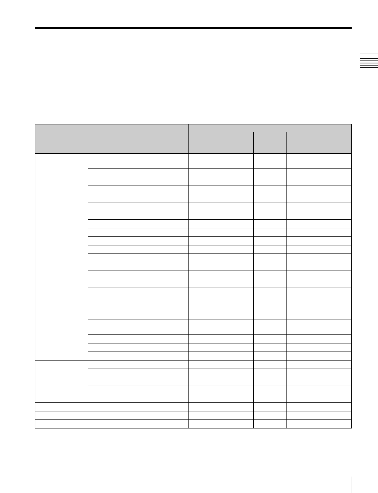
This monitor is equipped with two 3G/HD/SD-SDI input connectors, an HDMI input connector, and a DisplayPort input
connector for the standard interface.
In this manual, these connectors are referred to as the standard input.
By adding the optional input expansion adaptors, the input/output connector panel can be assembled in a wide variety of
configurations.
The signals that each connector supports are given in the following table. The type of signal to be applied to each input/
output connector is set with the Channel Configuration menu (page 58) .
List of input/output connectors and input adaptors
Input signal Standard
input
Serial digital
input
Analog input Composite NTSC a
HDMI Video a
DisplayPort Video a
Number of digital inputs 2 2 – – 2 2
Number of analog inputs – – 1 1 – –
Number of HDMI inputs 1 – – – – –
Number of DisplayPort input 1 – – – – –
Single-link SD-SDI
Component 525/625
Single-link HD-SDI aaa
Dual-link HD-SDI a (2) a
Single-link 3G-SDI aa
Composite PAL a
Composite PAL-M a
Composite SECAM a
Y/C NTSC a
Y/C PAL a
Y/C PAL-M a
Y/C SECAM a
YPbPr 525i/625i a
RGB 525i/625i a
YPbPr/RGB 1080/24PsF a
YPbPr/RGB 1080/24P a
YPbPr/RGB 1080/50i
(25PsF)
YPbPr/RGB 1080/25P a
YPbPr/RGB 1080/60i
(30PsF)
YPbPr/RGB 1080/30P a
YPbPr/RGB 720/50P a
YPbPr/RGB 720/60P a
Computer a
Computer a
aa aa
BKM-220D BKM-227W BKM-229X BKM-
a: Signal can be reproduced.
a(2): Two adaptors are used.
Input adaptor
a
a
243HS/
244CC
BKM250TG
Chapter 1 Overview
For details, see “Available Signal Formats” on page 124.
Input/Output Connectors and Input Adaptors
13
Page 14
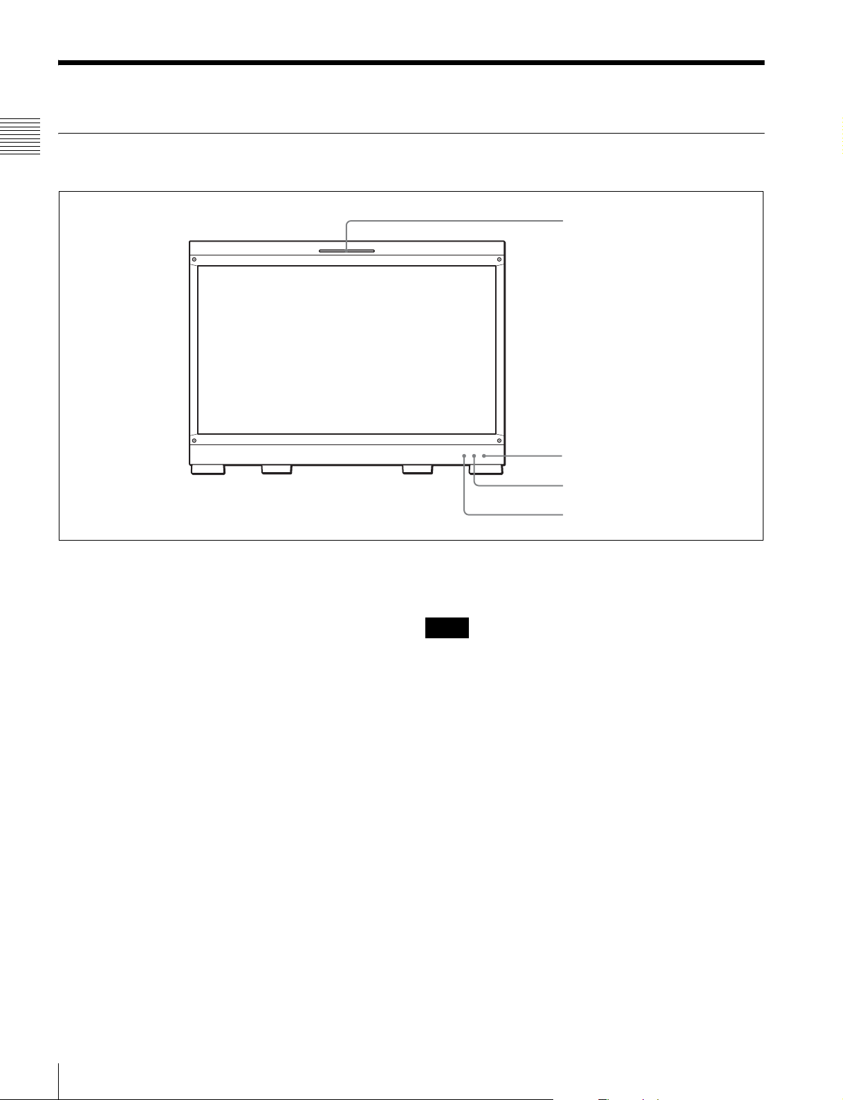
Location and Function of Parts (BVM-E250A)
Front Panel
Chapter 1 Overview
1 Tally lamp
2 OPERATE lamp
3 OVER RANGE lamp
a Tally lamp
With factory settings, the tally lamp lights when pins No. 8
and No. 9 of the PARALLEL REMOTE connector on the
left side panel are shorted. By changing the setting in the
Parallel Remote menu (page 82) of the System
Configuration menu, different pins on the PARALLEL
REMOTE connector can be used to control the tally lamp.
b OPERATE lamp
When the MAIN POWER switch (on the left side panel) is
turned on, internal data initialization starts and the
OPERATE lamp flashes in red for a while. When the signal
is output, the lamp flashes in green to indicate that data
initialization continues. When initialization is finished and
the monitor enters its operation mode, the lamp lights in
green.
The OPERATE lamp is lit in red when the monitor is in
standby mode. The monitor will be in standby mode under
the following conditions:
• Standby Mode is set to On in the Power menu (page 83)
of the System Configuration menu and the MAIN
POWER switch (on the left side panel) is turned on. (The
OPERATE lamp will flash for initialization after the
switch is turned on, then will light.)
• The monitor is changed from operation mode to standby
mode by external control.
4 ECO lamp
Lights in green when the monitor is put into operation
mode from standby mode by pressing the MONITOR I/1
switch of the controller.
Notes
• When the OPERATE lamp is flashing in red, the monitor
cannot be put into operation mode. Wait until the lamp is
steadily lit.
• When the OPERATE lamp is flashing in green, the
monitor is not in full operation mode and images cannot
be displayed correctly. Wait until the lamp is steadily lit
in green.
The OPERATE lamp may indicate an error or warning.
For details, see “Error/warning display by the lamp”
(page 15).
c OVER RANGE lamp
Lights in amber when ABL (Automatic Brightness
Limiter) starts. Also lights in amber when the signal level
has exceeded the dynamic range of the signal processing
circuit.
Decrease the contrast or brightness when the OVER
RANGE lamp is lit.
Location and Function of Parts (BVM-E250A)
14
Page 15
The OVER RANGE lamp may indicate an error or
warning. For details, see “Error/warning display by the
lamp” (page 15).
d ECO lamp
The color of the lamp changes according to the power
consumption status of the monitor. The color changes from
green to yellow to magenta in order of greater power
consumption. Decreasing the luminance of the screen by
adjusting brightness/contrast is recommended when the
lamp lights in yellow or magenta.
The lamp starts flashing rapidly approximately one minute
before the screen saver is activated. Flashing slows in
green when the screen saver starts.
The ECO lamp may indicate an error or warning. For
details, see “Error/warning display by the lamp”
(page 15).
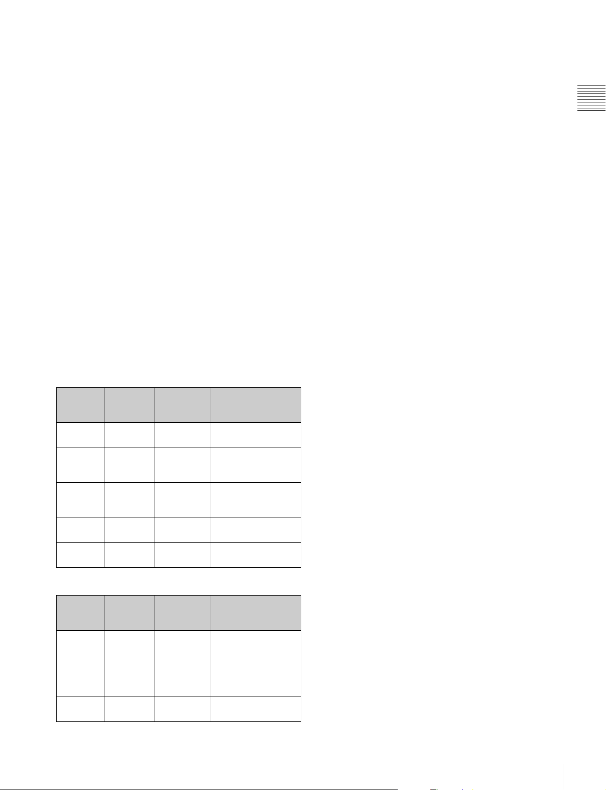
Error/warning display by the lamp
The OVER RANGE lamp, OPERATE lamp and/or ECO
lamp on the front panel may show an error or warning
while the monitor is being operated.
Chapter 1 Overview
If the error or warning is shown, please contact your Sony
representative.
Error display
ECO
lamp
Lights in
yellow
Lights in
yellow
Flashes in
yellow
Lights in
magenta
Flashes in
magenta
OVER
RANGE
lamp
Lights in
amber
Flashes in
amber
Lights in
amber
Flashes in
amber
Lights in
amber
OPERATE
lamp
Flashes in
red
Flashes in
red
Flashes in
red
Flashes in
red
Flashes in
red
Symptoms
The power in the
panel part is unusual.
The temperature in
the panel part is
unusual.
The ambient
temperature sensor is
unusual.
Fan error.
Device error.
Warning display
ECO
lamp
–: Status except for error display.
–
–
OVER
RANGE
lamp
Flashes in
amber
Lights in
amber
OPERATE
lamp
–
–
Symptoms
The luminance is
reduced to protect the
panel from an
increase of
temperature in the
panel part.
Over range
Location and Function of Parts (BVM-E250A)
15
Page 16
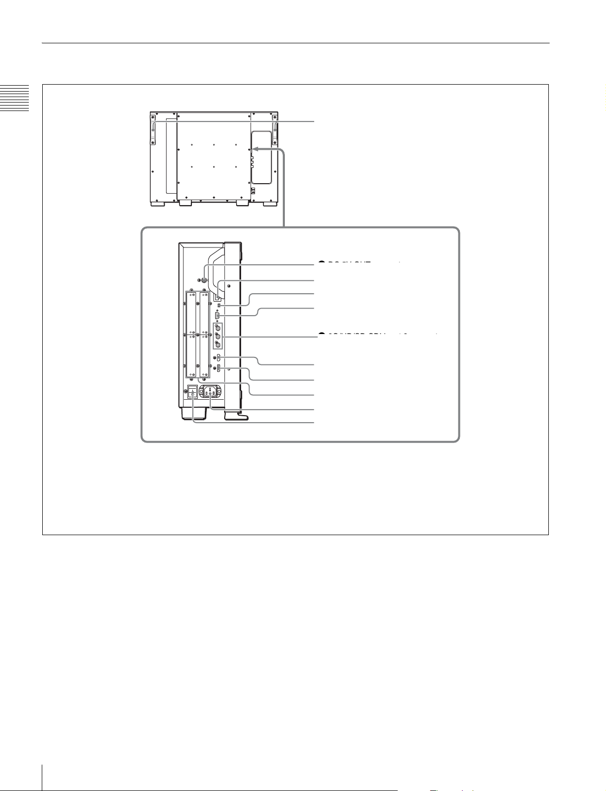
Rear Panel/Left Side Panel
Chapter 1 Overview
Handles
1 DC 5V OUT connector
1 DC 5V OUT connector
2 LAN (10/100) connector
3 NETWORK switch
4 PARALLEL REMOTE connector
6 3G/HD/SD-SDI input 2 connector
5 STANDARD PORT
6 HDMI input connector
7 DisplayPort input connector
8 Input option ports
9 AC IN connector
q; MAIN POWER switch
a DC 5V OUT connector (female)
Supplies the DC power to the controller.
Connect to the DC 5V/12V IN connector of the controller
with the SMF-700 or the cable supplied with the BKM37H/38H.
CAUTION
DC 5V OUT connector (female) is non LPS (Limited
Power Source) circuit.
b LAN (10/100) connector (10BASE-T/100BASE-TX)
Connect to the LAN (10/100) connector of the controller
by using the SMF-700 or the cable supplied with the BKM37H/38H. Or connect to the network or the LAN (10/100)
Location and Function of Parts (BVM-E250A)
16
connector of the controller by using a 10BASE-T/
100BASE-TX LAN cable (shielded-type, optional).
CAUTION
• For safety, do not connect the connector for peripheral
device wiring that might have excessive voltage to this
port. Follow the instructions for this port.
• When you connect the LAN cable of the unit to
peripheral device, use a shielded-type cable to prevent
malfunction due to radiation noise.
• The connection speed may be affected by the network
system.
Page 17
c NETWORK switch
LAN: To connect to the network.
PEER TO PEER: To connect to the LAN (10/100)
connector of the controller in 1 to 1 connection.
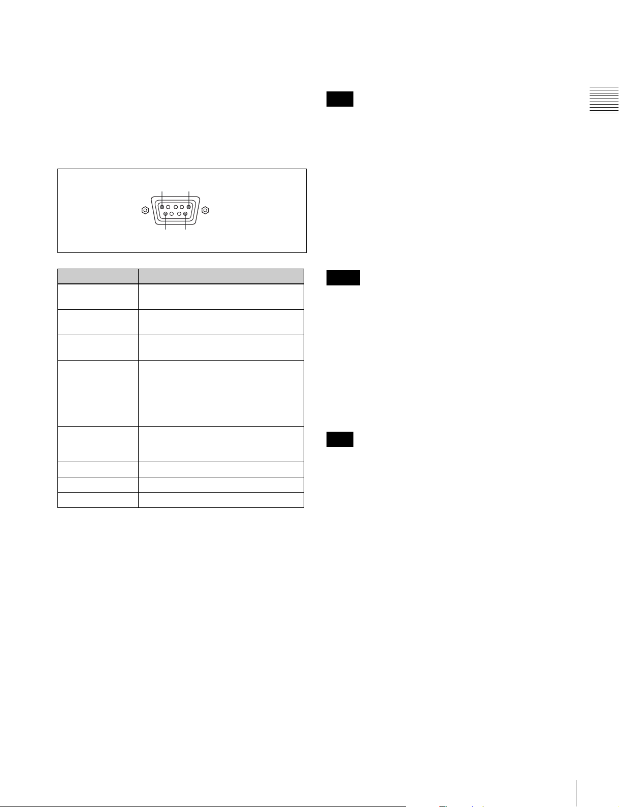
d PARALLEL REMOTE connector (D-sub 9-pin,
female)
Forms a parallel switch and controls the monitor
externally. The pin assignment and factory setting
function assigned to each pin are given below.
15
96
MONITOR OUT connector
This is the MONITOR OUT connector for SDI INPUT 1 or
SDI INPUT 2 connector.
Note
The signal from this MONITOR OUT connector does not
satisfy the ON-LINE signal specifications.
f HDMI input connector
Inputs the HDMI signal.
HDMI (High-Definition Multimedia Interface) is an
interface that supports both video and audio on a single
digital connection, allowing you to display high quality
digital picture. The HDMI specification supports HDCP
(High-bandwidth Digital Content Protection), a copy
protection technology that incorporates coding technology
for digital video signals.
Chapter 1 Overview
Pin number Function
1 Sets input signal channel 1 (numeric
keypad function).
2 Sets input signal channel 2 (numeric
keypad function).
3 Selects sync signal (SYNC button
function).
4 Selects whether monochrome image is
displayed or the monitor switches the
display mode automatically between
color image and monochrome image
depending on the input signal (MONO
button function).
5 Marker (set in the Marker Setting
menu) On/Off (MARKER button
function).
6, 7 Not connected
8 Tally lamp On/Off
9Ground
All pin function assignments can be changed with the
Parallel Remote menu (page 82) of the System
Configuration menu.
To switch each function between On and Off or between
enable and disable, change pin connections in the
following way.
On or enabled: Short each pin and pin 9 together.
Off or disabled: Leave each pin open.
e STANDARD PORT
SDI INPUT 1 connector
Inputs serial digital signals (standard SDI input 1).
SDI INPUT 2 connector
Inputs serial digital signals (standard SDI input 2).
Notes
• The HDMI audio signal is not available for this monitor.
• Use HDMI compliant cable (optional), Category 2 (High
Speed HDMI Cable), with HDMI logo.
g DisplayPort input connector
Inputs the DisplayPort signal.
DisplayPort is an interface developed by VESA that
supports transfer of both video and audio digital signals on
a single cable.
It also supports HDCP, a copy protection technology that
incorporates coding technology for digital video signals.
Note
This monitor does not support DisplayPort audio signals.
h Input option ports
Used to install the optional input adaptors.
For installing the input adaptor, see page 23.
For the input signals, see “Input/Output Connectors and
Input Adaptors” on page 13.
i AC IN connector (3-pin)
Connects the monitor to an AC power source, via the
supplied AC power cord.
j MAIN POWER switch
When turned on (?), the monitor enters operation mode. By
setting in the Power menu (page 83) of the System
Configuration menu, the monitor can also be set to enter
standby mode when the MAIN POWER switch is turned
on.
Location and Function of Parts (BVM-E250A)
17
Page 18
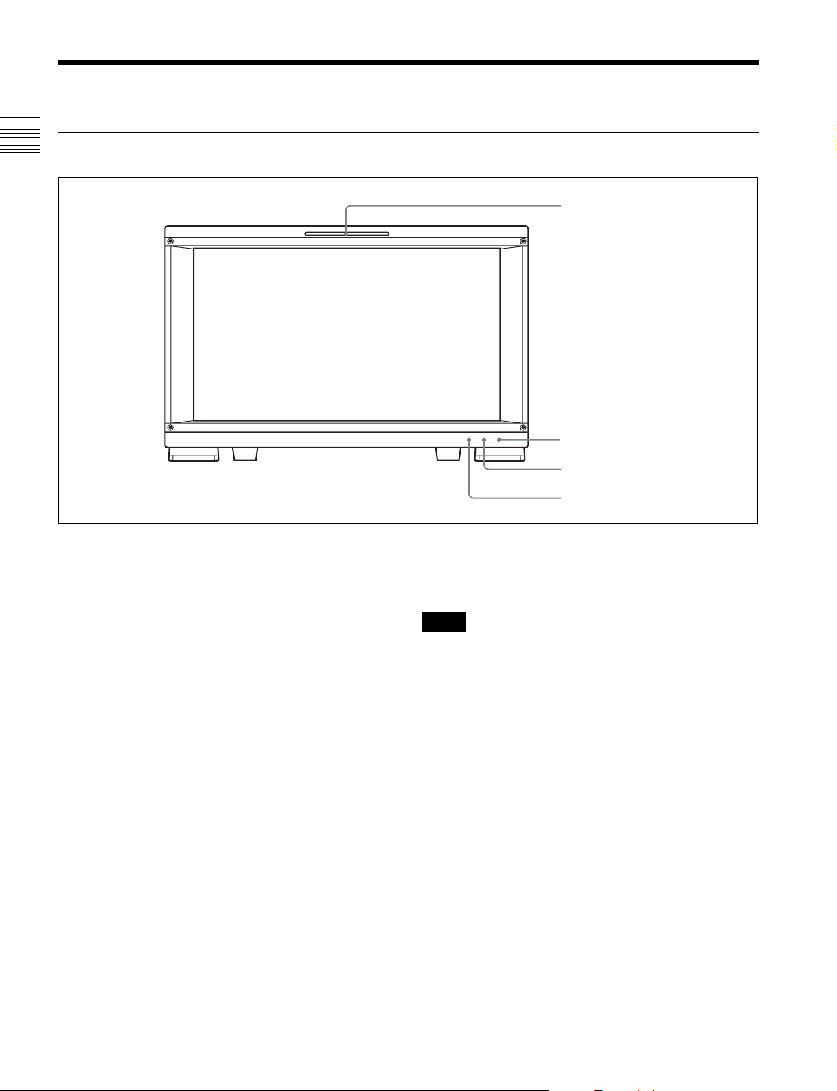
Location and Function of Parts (BVM-E170A)
Front Panel
Chapter 1 Overview
1 Tally lamp
2 OPERATE lamp
3 OVER RANGE lamp
a Tally lamp
With factory settings, the tally lamp lights when pins No. 8
and No. 9 of the PARALLEL REMOTE connector on the
rear panel are shorted. By changing the setting in the
Parallel Remote menu (page 82) of the System
Configuration menu, different pins on the PARALLEL
REMOTE connector can be used to control the tally lamp.
b OPERATE lamp
When the MAIN POWER switch (on the rear panel) is
turned on, internal data initialization starts and the
OPERATE lamp flashes in red for a while. When the signal
is output, the lamp flashes in green to indicate that data
initialization continues. When initialization is finished and
the monitor enters its operation mode, the lamp lights in
green.
The OPERATE lamp is lit in red when the monitor is in
standby mode. The monitor will be in standby mode under
the following conditions:
• Standby Mode is set to On in the Power menu (page 83)
of the System Configuration menu and the MAIN
POWER switch (on the rear panel) is turned on. (The
OPERATE lamp will flash for initialization after the
switch is turned on, then will light.)
• The monitor is changed from operation mode to standby
mode by external control.
4 ECO lamp
Lights in green when the monitor is put into operation
mode from standby mode by pressing the MONITOR I/1
switch of the controller.
Notes
• When the OPERATE lamp is flashing in red, the monitor
cannot be put into operation mode. Wait until the lamp is
steadily lit.
• When the OPERATE lamp is flashing in green, the
monitor is not in full operation mode and images cannot
be displayed correctly. Wait until the lamp is steadily lit
in green.
The OPERATE lamp may indicate an error or warning.
For details, see “Error/warning display by the lamp”
(page 19).
c OVER RANGE lamp
Lights in amber when ABL (Automatic Brightness
Limiter) starts. Also lights in amber when the signal level
has exceeded the dynamic range of the signal processing
circuit.
Decrease the contrast or brightness when the OVER
RANGE lamp is lit.
Location and Function of Parts (BVM-E170A)
18
Page 19
The OVER RANGE lamp may indicate an error or
warning. For details, see “Error/warning display by the
lamp” (page 19).
d ECO lamp
The color of the lamp changes according to the power
consumption status of the monitor. The color changes from
green to yellow to magenta in order of greater power
consumption. Decreasing the luminance of the screen by
adjusting brightness/contrast is recommended when the
lamp lights in yellow or magenta.
The lamp starts flashing rapidly approximately one minute
before the screen saver is activated. Flashing slows in
green when the screen saver starts.
The ECO lamp may indicate an error or warning. For
details, see “Error/warning display by the lamp”
(page 19).
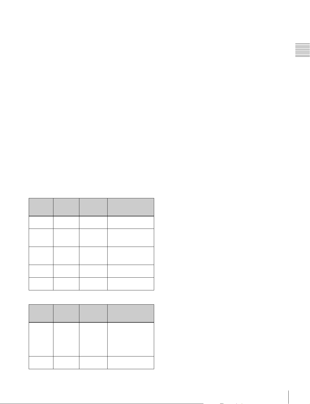
Error/warning display by the lamp
The OVER RANGE lamp, OPERATE lamp and/or ECO
lamp on the front panel may show an error or warning
while the monitor is being operated.
Chapter 1 Overview
If the error or warning is shown, please contact your Sony
representative.
Error display
ECO
lamp
Lights in
yellow
Lights in
yellow
Flashes in
yellow
Lights in
magenta
Flashes in
magenta
OVER
RANGE
lamp
Lights in
amber
Flashes in
amber
Lights in
amber
Flashes in
amber
Lights in
amber
OPERATE
lamp
Flashes in
red
Flashes in
red
Flashes in
red
Flashes in
red
Flashes in
red
Symptoms
The power in the
panel part is unusual.
The temperature in
the panel part is
unusual.
The ambient
temperature sensor is
unusual.
Fan error.
Device error.
Warning display
ECO
lamp
–: Status except for error display.
–
–
OVER
RANGE
lamp
Flashes in
amber
Lights in
amber
OPERATE
lamp
–
–
Symptoms
The luminance is
reduced to protect the
panel from an
increase of
temperature in the
panel part.
Over range
Location and Function of Parts (BVM-E170A)
19
Page 20
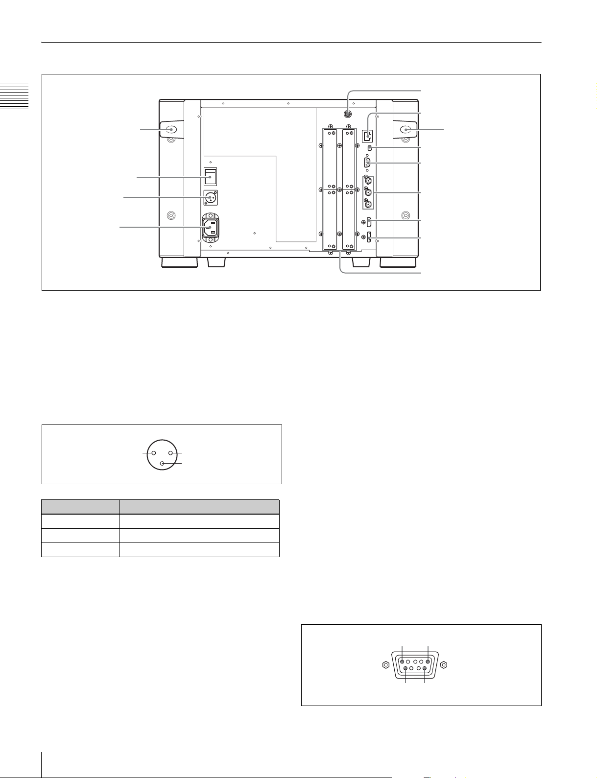
Rear Panel
4 DC 5V OUT connector
Chapter 1 Overview
Handle
1 MAIN POWER switch
2 DC IN 24 V - 28 V
connector
3 AC IN connector
a MAIN POWER switch
When turned on, the monitor enters operation mode. By
setting in the Power menu (page 83) of the System
Configuration menu, the monitor can also be set to enter
standby mode when the MAIN POWER switch is turned
on.
b DC IN 24 V - 28 V (DC power input) connector
(XLR 3-pin, male)
Connect the 24 V to 28 V DC power supply.
21
3
5 LAN (10/100) connector
Handle
6 NETWORK switch
7 PARALLEL REMOTE
connector
8 STANDARD PORT
9 HDMI IN connector
q; DisplayPort input connector
qa Input option ports
e LAN (10/100) connector (10BASE-T/100BASE-TX)
Connect to the LAN (10/100) connector of the controller
by using the SMF-700 or the cable supplied with the BKM39H. Or connect to the network or the LAN (10/100)
connector of the controller by using a 10BASE-T/
100BASE-TX LAN cable (shielded-type, optional).
CAUTION
• For safety, do not connect the connector for peripheral
device wiring that might have excessive voltage to this
port. Follow the instructions for this port.
• When you connect the LAN cable of the unit to
peripheral device, use a shielded-type cable to prevent
malfunction due to radiation noise.
• The connection speed may be affected by the network
system.
Pin number Function
1 – (GND)
2 + (24 V to 28 V DC)
3NC
c AC IN connector (3-pin)
Connects the monitor to an AC power source, via the
supplied AC power cord.
d DC 5V OUT connector (female)
Supplies the DC power to the controller.
Connect to the DC 5V/12V IN connector of the controller
with the SMF-700 or the cable supplied with the BKM39H.
CAUTION
DC 5V OUT connector (female) is non LPS (Limited
Power Source) circuit.
Location and Function of Parts (BVM-E170A)
20
f NETWORK switch
LAN: To connect to the network.
PEER TO PEER: To connect to the LAN (10/100)
connector of the controller in 1 to 1 connection.
g PARALLEL REMOTE connector (D-sub 9-pin,
female)
Forms a parallel switch and controls the monitor
externally. The pin assignment and factory setting
function assigned to each pin are given below.
15
96
Page 21
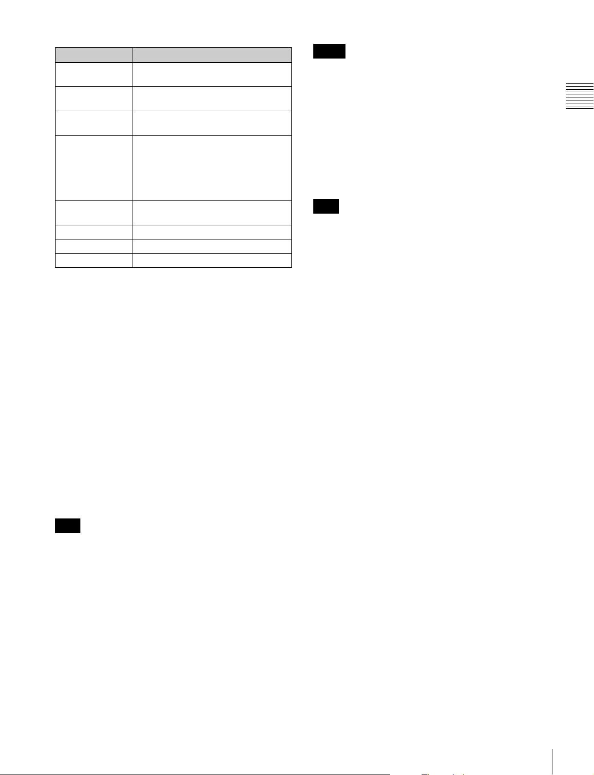
Pin number Function
1 Sets input signal channel 1 (numeric
keypad function).
2 Sets input signal channel 2 (numeric
keypad function).
3 Selects sync signal (SYNC button
function).
4 Selects whether monochrome image is
displayed or the monitor switches the
display mode automatically between color
image and monochrome image
depending on the input signal (MONO
button function).
5 Marker (set in the Marker Setting menu)
On/Off (MARKER button function).
6, 7 Not connected
8 Tally lamp On/Off
9 Ground
Notes
• The HDMI audio signal is not available for this monitor.
• Use HDMI compliant cable (optional), Category 2 (High
Speed HDMI Cable), with HDMI logo.
j DisplayPort input connector
Inputs the DisplayPort signal.
DisplayPort is an interface developed by VESA that
supports transfer of both video and audio digital signals on
a single cable.
It also supports HDCP, a copy protection technology that
incorporates coding technology for digital video signals.
Note
This monitor does not support DisplayPort audio signals.
k Input option ports
Used to install the optional input adaptors.
Chapter 1 Overview
All pin function assignments can be changed with the
Parallel Remote menu (page 82) of the System
Configuration menu.
To switch each function between On and Off or between
enable and disable, change pin connections in the
following way.
On or enabled: Short each pin and pin 9 together.
Off or disabled: Leave each pin open.
h STANDARD PORT
SDI INPUT 1 connector
Inputs serial digital signals (standard SDI input 1).
SDI INPUT 2 connector
Inputs serial digital signals (standard SDI input 2).
MONITOR OUT connector
This is the MONITOR OUT connector for SDI INPUT 1 or
SDI INPUT 2 connector.
Note
The signal from this MONITOR OUT connector does not
satisfy the ON-LINE signal specifications.
For installing the input adaptor, see page 25.
For the input signals, see “Input/Output Connectors and
Input Adaptors” on page 13.
i HDMI IN connector
Inputs the HDMI signal.
HDMI (High-Definition Multimedia Interface) is an
interface that supports both video and audio on a single
digital connection, allowing you to display high quality
digital picture. The HDMI specification supports HDCP
(High-bandwidth Digital Content Protection), a copy
protection technology that incorporates coding technology
for digital video signals.
Location and Function of Parts (BVM-E170A)
21
Page 22
Preparations
Chapter 2 Preparations
Chapter
2
Environments of the Installation Location
Illumination environments
The apparent color reproduction on the monitor is greatly
affected by ambient light or glare.
Viewing angle
The ideal viewing angle is within 5 degrees (up/down/left/
right) off the center of the monitor screen when the
operator views the entire monitor screen. Keep the
viewing angle within 15 degrees off the center of the
monitor screen.
Input Adaptors
Each input adaptor can be installed in any input option
port on the monitor.
Caution
When you install the following input adaptors to this
equipment, use those with the serial numbers given below.
• BKM-220D with serial number 2100001 or higher
This equipment may not meet the requirements of the
electromagnetic interference standard if designated
input adaptors are not installed.
• BKM-227W with serial number 2100001 or higher
This equipment may not work correctly or you may not
be satisfied with their performance if designated input
adaptors are not installed.
• BKM-229X with serial number 2200001 or higher
This equipment may not work correctly or you may not
be satisfied with their performance if designated input
adaptors are not installed.
• BKM-243HS with serial number 2108355 or higher
This equipment may not meet the requirements of the
electromagnetic interference standard or work
correctly, or you may not be satisfied with the
performance if designated input adaptors are not
installed.
• BKM-250TG with serial number 7300001 or higher
To enable all five display modes of the 3D signal
analyzing function, use the input adaptor with serial
number 7300001 or higher.
Environments of the Installation Location / Input Adaptors
22
Caution
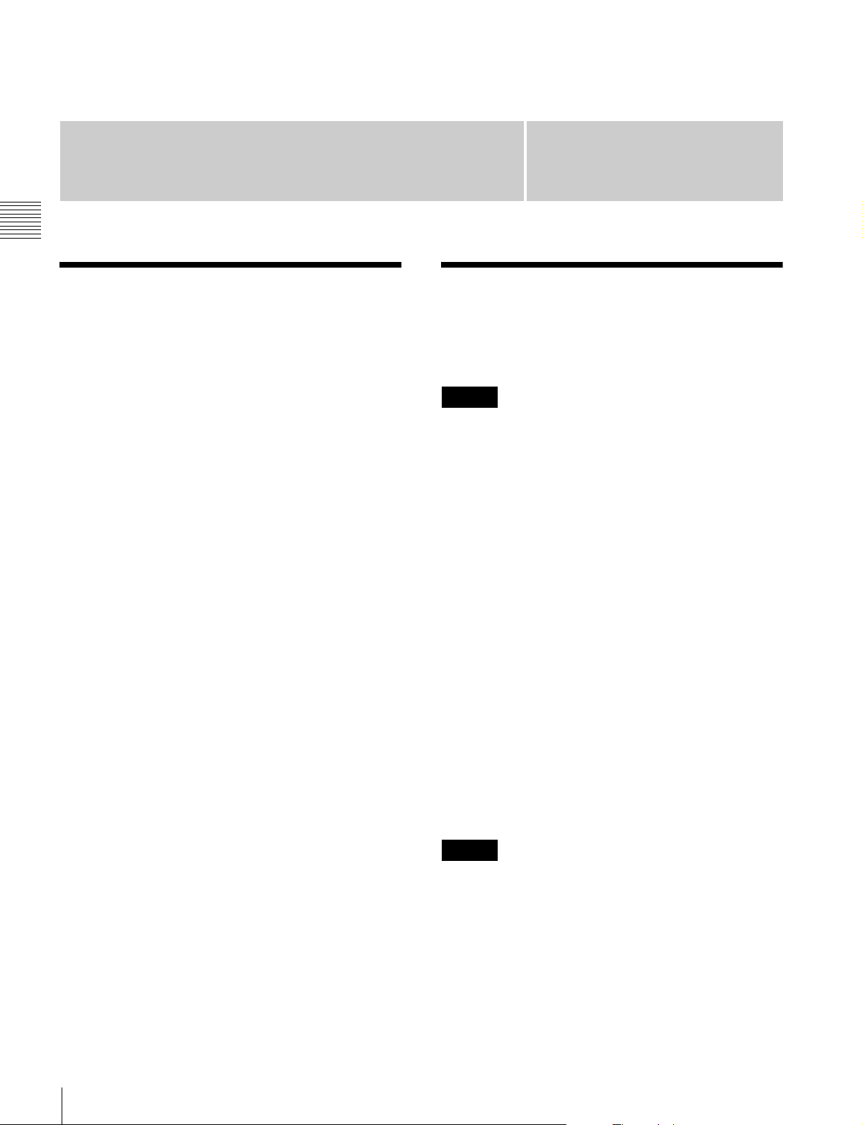
To reduce the risk of electric shock, turn off the MAIN
POWER switch of the monitor and disconnect the AC
power cord before installing or removing adaptors.
Page 23
Version of the Controller
To use all the functions of the monitor, the controller
(BKM-16R) with software version 1.7 or higher is
required.
Certain functions of the monitor cannot be controlled if the
controller with a lower version is used.
Installing an Input Adaptor (BVM-E250A)
1
Loosen two screws and remove the cover of an input
option port on the side panel of the monitor.
Cover of an input
option port
Make sure the MAIN
POWER switch is turned
off, and disconnect the AC
power cord.
Chapter 2 Preparations
Off
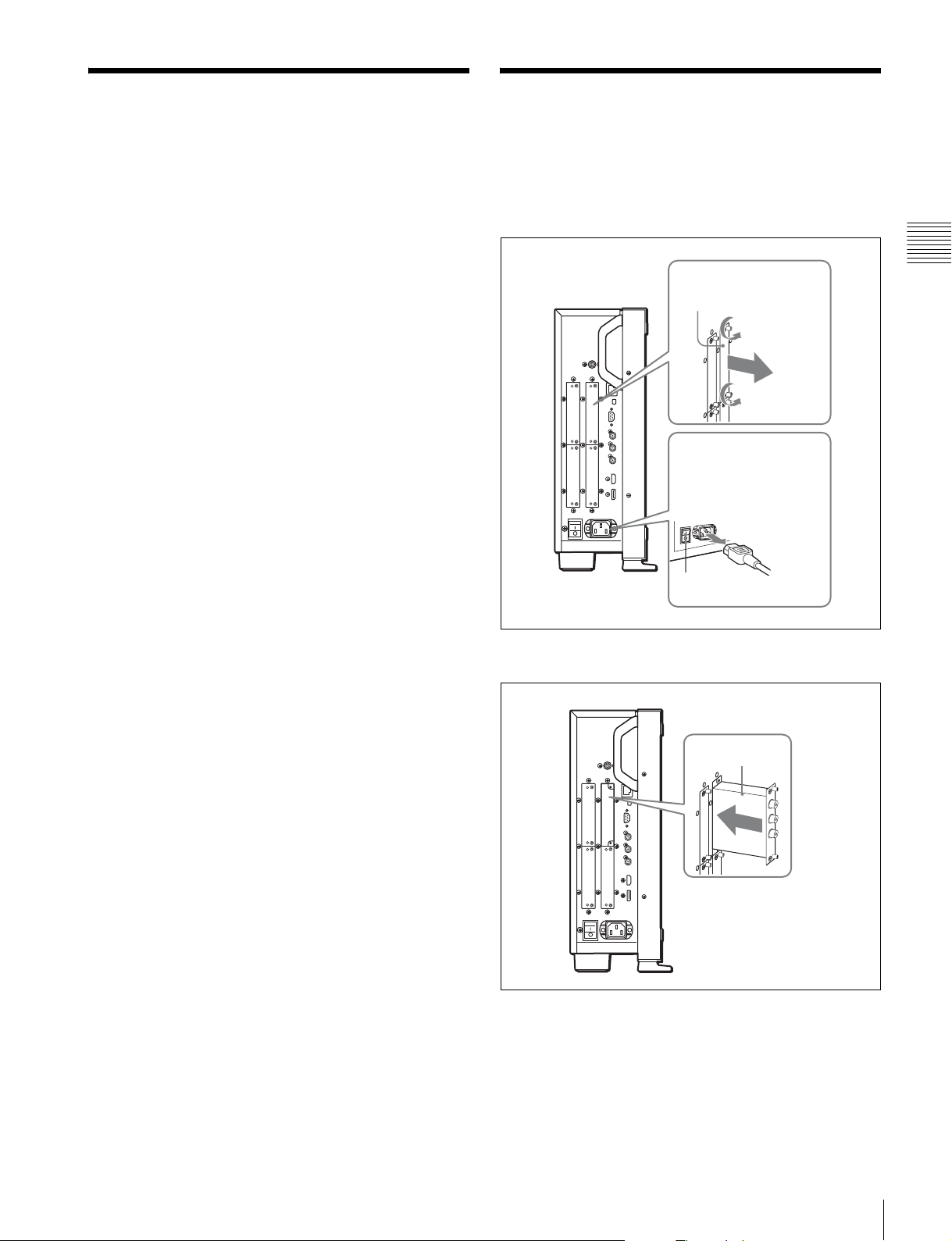
2
Insert the adaptor facing the board as shown below.
Board
3
Push the adaptor in until it is firmly fit into the
connector inside the monitor, then tighten the two
screws to secure the adaptor.
Version of the Controller / Installing an Input Adaptor (BVM-E250A)
23
Page 24
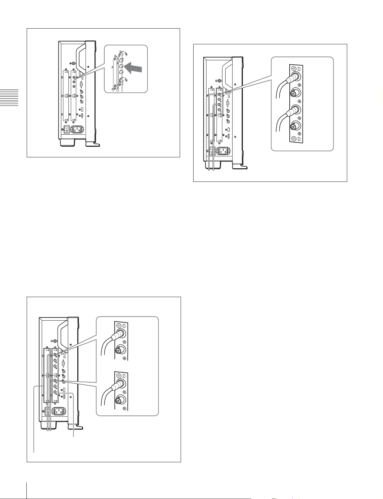
When the BKM-250TG is used, install the Link A signal
to INPUT 1, and the Link B signal to INPUT 2.
INPUT 1
Chapter 2 Preparations
For connecting Dual-link HD-SDI signals
Two BKM-243HS or BKM-244CC input adaptors or one
BKM-250TG input adaptor is required. When the BKM243HS or BKM-244CC adaptors are used, install the input
adaptors in OPTION 1 and 2 option ports, or OPTION 3
and 4 option ports. The BKM-243HS or BKM-244CC
cannot be used with the BKM-250TG for Dual-link
operation.
To connect the cable
When the BKM-243HS or BKM-244CC adaptors are
used, install the Link A signal to OPTION 1 or 3, and the
Link B signal to OPTION 2 or 4.
Connect the cable to the same input number (both INPUT 1
or both INPUT 2) of the input adaptors installed in
OPTION 1 and 2 option ports, or OPTION 3 and 4 option
ports.
INPUT 2
For 3D signal analyzing function
Use a 3D-compatible BKM-250TG (with serial number
7300001 or higher) and input the left 3D signal to INPUT 1
and the right signal to INPUT 2.
Example of Dual-link cable connection
OPTION 1 and 2
OPTION 3 and 4
Installing an Input Adaptor (BVM-E250A)
24
INPUT 1
INPUT 2
INPUT 1
INPUT 2
Page 25
Installing an Input Adaptor (BVM-E170A)
1
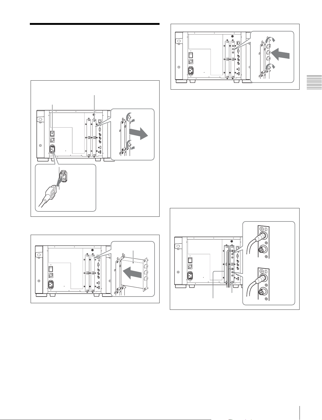
Loosen two screws and remove the cover of an input
option port on the rear panel of the monitor.
Make sure the MAIN
POWER switch is turned
off, and disconnect the AC
power cord.
2
Insert the adaptor facing the board as shown below.
Cover of an input
option port
Chapter 2 Preparations
For connecting Dual-link HD-SDI signals
Two BKM-243HS or BKM-244CC input adaptors or one
BKM-250TG input adaptor is required. When the BKM243HS or BKM-244CC adaptors are used, install the input
adaptors in OPTION 1 and 2 option ports, or OPTION 3
and 4 option ports. The BKM-243HS or BKM-244CC
cannot be used with the BKM-250TG for Dual-link
operation.
To connect the cable
When the BKM-243HS or BKM-244CC adaptors are
used, install the Link A signal to OPTION 1 or 3, and the
Link B signal to OPTION 2 or 4.
Connect the cable to the same input number (both INPUT 1
or both INPUT 2) of the input adaptors installed in
OPTION 1 and 2 option ports, or OPTION 3 and 4 option
ports.
Example of Dual-link cable connection
INPUT 1
Board
3
Push the adaptor in until it is firmly fit into the
connector inside the monitor, then tighten the two
screws to secure the adaptor.
INPUT 2
INPUT 1
INPUT 2
OPTION 3 and 4
OPTION 1
and 2
When the BKM-250TG is used, install the Link A signal
to INPUT 1, and the Link B signal to INPUT 2.
Installing an Input Adaptor (BVM-E170A)
25
Page 26
Preventing Falling of the
INPUT 1
INPUT 2
Chapter 2 Preparations
For 3D signal analyzing function
Use a 3D-compatible BKM-250TG (with serial number
7300001 or higher) and input the left 3D signal to INPUT 1
and the right signal to INPUT 2.
Monitor (BVM-E250A)
1
Tie a piece of stout string (commercially available) to
the left and right handles of the monitor.
String
2
Secure the ends of the string to the floor or wall.
String
String
Preventing Falling of the Monitor (BVM-E250A)
26
Page 27
Mounting the Unit in a
Connections
Rack (BVM-E170A)
To mount the unit in an EIA standard 19-inch rack, use the
supplied rack mount brackets and screws.
1
Remove the four feet from the bottom of the unit.
2
Attach the rack mount brackets to each side of the unit
with the rack mount attachment screws.
Rack mount bracket
Rack mount
attachment screws
3
Screw the rack mount brackets to the rack to mount the
unit.
(BVM-E250A)
Note on connecting the cable to the DC 5V OUT
connector
Be sure to plug the male connector of the cable into the DC
5V OUT connector of the monitor.
Insert the connector so as to fit the shape of the DC 5V
OUT connector.
Plug the male
connector into
the monitor.
Chapter 2 Preparations
Use the commercially available screws that match the
size of the rack’s holes.
Rack
Mounting the Unit in a Rack (BVM-E170A) / Connections (BVM-E250A)
27
Page 28
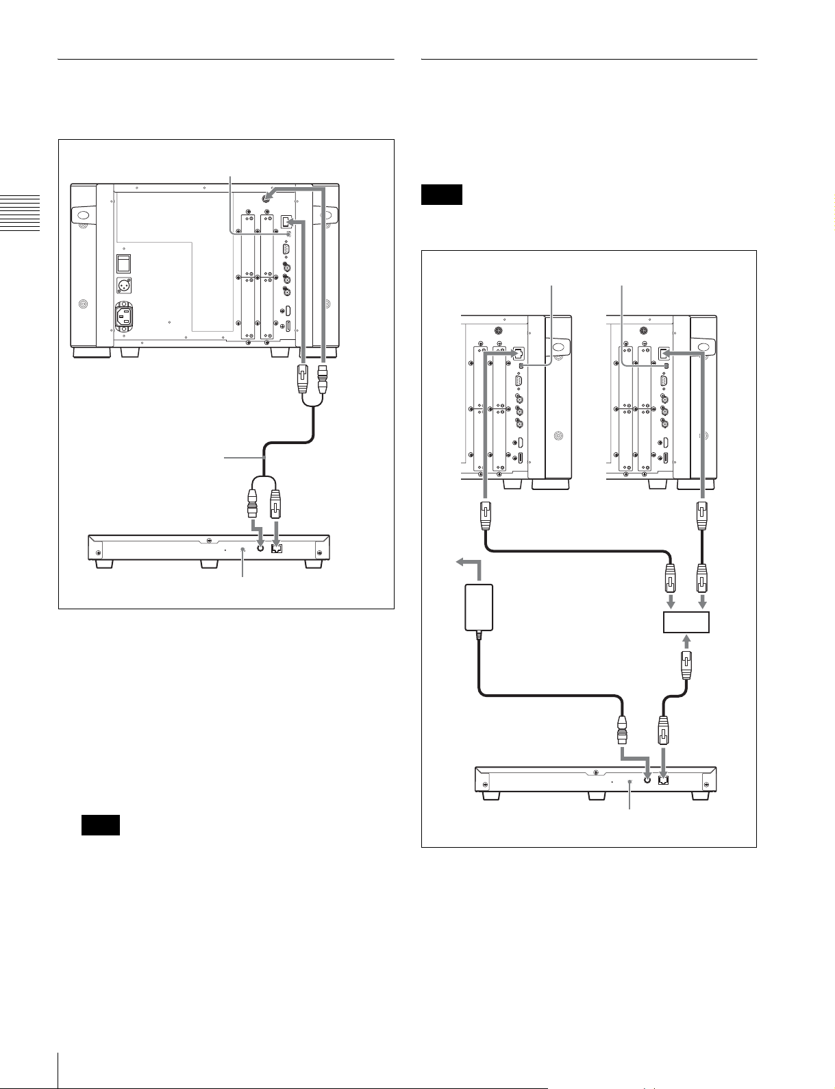
Connecting the Controller (BKM16R)
with the controller to the DC 5V/12V IN connector of
the controller.
Connecting the Multiple Units with
Chapter 2 Preparations
NETWORK switch
t Set to PEER TO
PEER.
Controller
(BKM-16R)
BVM-E250A
LAN (10/100) connector
SMF-700, etc.
DC 5V/12V IN
connector
DC 5V OUT
connector
LAN (10/100)
connector
the LAN
The controller controls up to 32 monitors. Up to four
controllers are connected to one monitor in single mode.
Note
The controller cannot control monitors in another
subnetwork.
NETWORK switch
tSet to LAN.
BVM-E250A
LAN (10/100)
connector
BVM-E250A
LAN (10/100)
connector
NETWORK switch
tSet to PEER TO PEER.
1
Turn off the MAIN POWER switch of the monitor
before connecting the units.
2
Set the NETWORK switches of the monitor and the
controller to PEER TO PEER.
3
Connect the LAN (10/100) connector of the monitor
and the LAN (10/100) connector of the controller by
using the SMF-700 or the cable supplied with the
BKM-37H/38H, or a 10BASE-T/100BASE-TX
straight LAN cable (shielded-type, optional).
Note
When an optional LAN cable is connected, use a
shielded-type cable to prevent a malfunction due to
noises.
4
Connect the DC 5V OUT connector of the monitor and
the DC 5V/12V IN connector of the controller by using
the SMF-700 or the cable supplied with the BKM-37H/
38H.
Or connect the output cable of the AC adaptor supplied
AC adaptor (supplied
with the BKM-16R)
Switching hub
(recommended: with
AUTO MDI/MDI-X
function)
DC 5V/12V IN
connector
Controller
(BKM-16R)
NETWORK switch
tSet to LAN.
1
Turn off the MAIN POWER switch of the monitor
LAN (10/100)
connector
before connecting the units.
2
Connect to the network by using a 10BASE-T/
100BASE-TX cable (shielded-type, optional).
Connections (BVM-E250A)
28
Page 29
Notes
• When an optional LAN cable is connected, use a
shielded-type cable to prevent a malfunction due to
noises.
• We recommend to use an optional switching hub
with auto selection function (AUTO MDI/MDI-X)
of a straight/cross cable.
3
Connect the output cable on the AC adaptor supplied
with controller to the DC 5V/12V IN connector of the
controller.
Note
When the multiple units are connected, set for the LAN
before setting the NETWORK switch to LAN (page
35).
4
Set the NETWORK switches of each monitor and the
controller to LAN.
Connections (BVM-E170A)
Note on connecting the cable to the DC 5V OUT
connector
Be sure to plug the male connector of the cable into the DC
5V OUT connector of the monitor.
Insert the connector so as to fit the shape of the DC 5V
OUT connector.
Plug the male
connector into
the monitor.
Chapter 2 Preparations
Connections (BVM-E170A)
29
Page 30
Connecting the Controller (BKM-
Connecting the Multiple Units with
Chapter 2 Preparations
16R)
Controller
(BKM-16R)
BVM-E170A
NETWORK switch
t Set to PEER TO PEER.
LAN (10/100) connector
SMF-700, etc.
DC 5V/12V IN
connector
DC 5V
OUT
connector
LAN (10/100)
connector
the LAN
The controller controls up to 32 monitors. Up to four
controllers are connected to one monitor in single mode.
Note
The controller cannot control monitors in another
subnetwork.
NETWORK switch
tSet to LAN.
BVM-E170A
LAN (10/100)
connector
BVM-E170A
LAN (10/100)
connector
NETWORK switch
tSet to PEER TO PEER.
1
Turn off the MAIN POWER switch of the monitor
before connecting the units.
2
Set the NETWORK switches of the monitor and the
controller to PEER TO PEER.
3
Connect the LAN (10/100) connector of the monitor
and the LAN (10/100) connector of the controller by
using the SMF-700 or the cable supplied with the
BKM-39H, or a 10BASE-T/100BASE-TX straight
LAN cable (shielded-type, optional).
Note
When an optional LAN cable is connected, use a
shielded-type cable to prevent a malfunction due to
noises.
4
Connect the DC 5V OUT connector of the monitor and
the DC 5V/12V IN connector of the controller by using
the SMF-700 or the cable supplied with the BKM-39H.
Or connect the output cable of the AC adaptor supplied
with the controller to the DC 5V/12V IN connector of
the controller.
Switching hub
(recommended: with
AUTO MDI/MDI-X
function)
AC adaptor (supplied
with the BKM-16R)
DC 5V/12V IN
connector
Controller
(BKM-16R)
1
Turn off the MAIN POWER switch of the monitor
NETWORK switch
tSet to LAN.
LAN (10/100)
connector
before connecting the units.
2
Connect to the network by using a 10BASE-T/
100BASE-TX cable (shielded-type, optional).
Connections (BVM-E170A)
30
Page 31
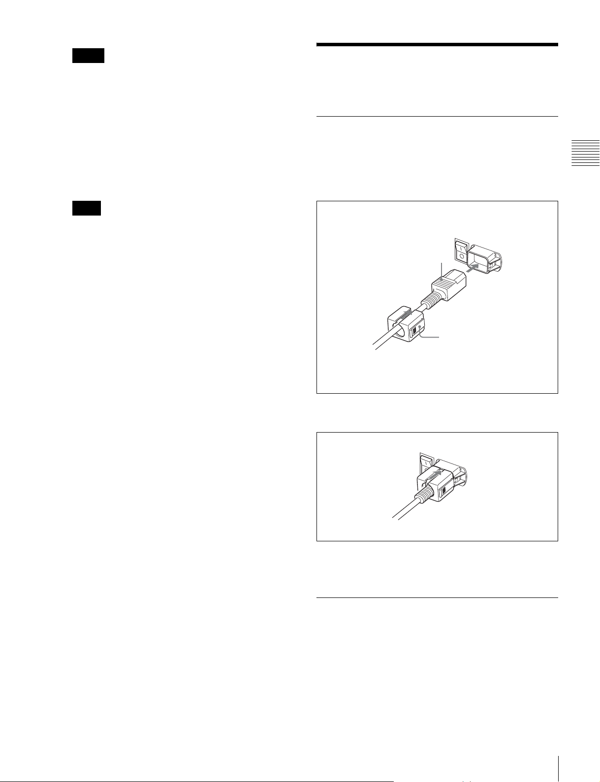
Notes
• When an optional LAN cable is connected, use a
shielded-type cable to prevent a malfunction due to
noises.
• We recommend to use an optional switching hub
with auto selection function (AUTO MDI/MDI-X)
of a straight/cross cable.
3
Connect the output cable on the AC adaptor supplied
with controller to the DC 5V/12V IN connector of the
controller.
Note
When the multiple units are connected, set for the LAN
before setting the NETWORK switch to LAN (page
35).
4
Set the NETWORK switches of each monitor and the
controller to LAN.
Turning on the Power (BVM-E250A)
Connecting the AC Power Cord
1
Plug the AC power cord into the AC IN connector on
the left side panel. Then, attach the AC plug holder
(supplied) to the AC power cord.
AC power cord (supplied)
Chapter 2 Preparations
AC plug holder (supplied)
Attach the AC plug holder to the AC power cord, and connect
the cord to the AC IN connector so that the cord does not come
loose.
2
Slide the AC plug holder over the cord until it locks.
To disconnect the AC power cord
Pull out the AC plug holder while pressing the lock levers.
Turning on the Monitor
Press the MAIN POWER switch on the left side panel to
turn on the power.
When you turn on the monitor for the first time after
purchasing it, the Select Area screen is displayed. Select
the area where you intend to use this monitor.
For selecting the area, see page 33.
Turning on the Power (BVM-E250A)
31
Page 32
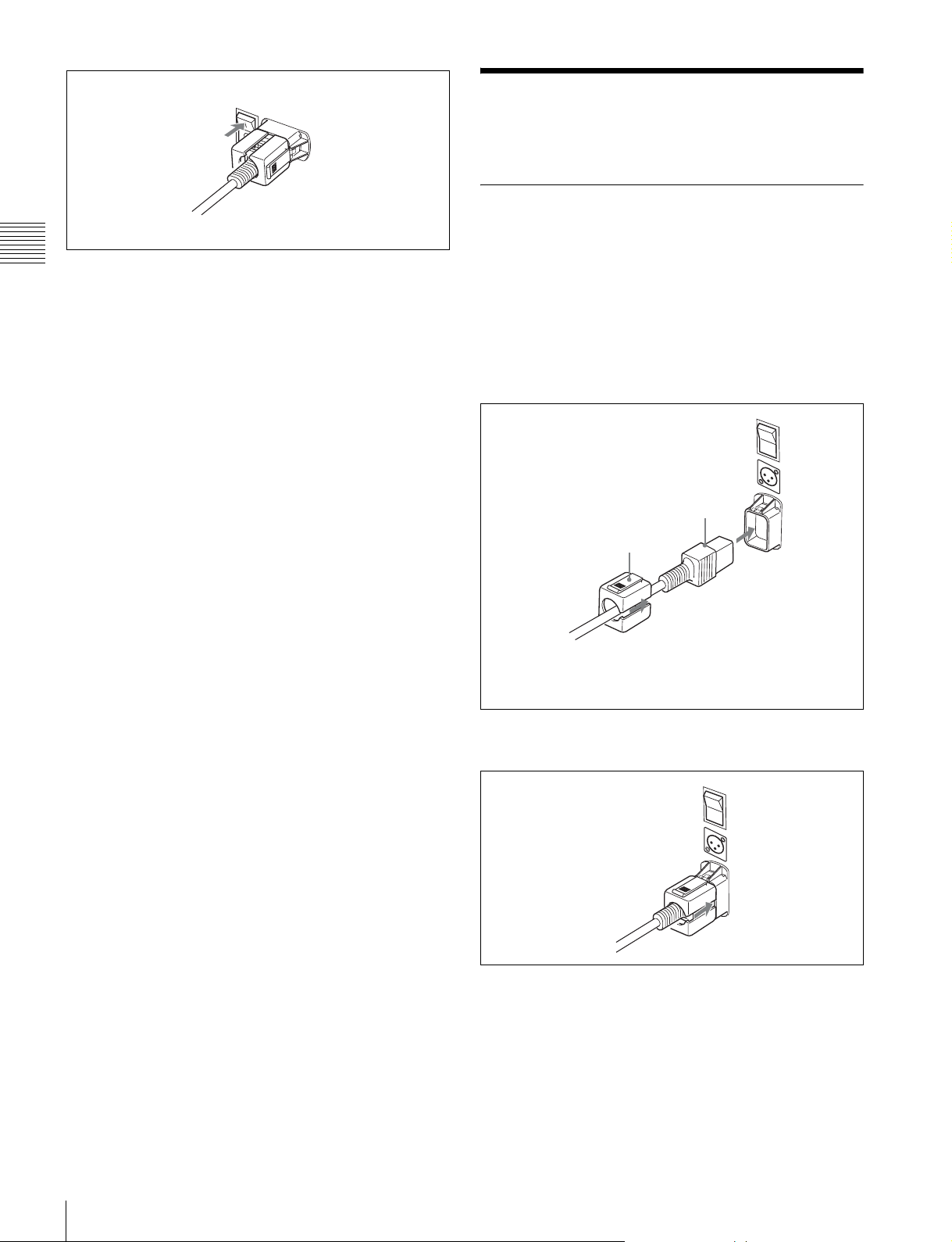
Turning on the Power (BVM-E170A)
Connecting to Power
Chapter 2 Preparations
The warm-up time is more than 30 minutes, approximately.
When the monitor is in standby mode
As the OPERATE lamp lights in red in standby mode,
press the MONITOR I/1 switch of the controller.
The OPERATE lamp lights in green and the monitor enters
operation mode.
You can operate the monitor with AC or DC power supply.
To connect the AC power cord
1
Plug the AC power cord into the AC IN connector on
the rear panel. Then, attach the AC plug holder
(supplied) to the AC power cord.
AC power cord (supplied)
AC plug holder (supplied)
Attach the AC plug holder to the AC power cord, and connect
the cord to the AC IN connector so that the cord does not come
loose.
2
Slide the AC plug holder over the cord until it locks.
To disconnect the AC power cord
Pull out the AC plug holder while pressing the lock levers.
To connect the DC power supply
Connect the DC power supply to the DC IN 24 V - 28 V
connector.
When the AC power cord and DC power supply are
connected, the AC power supply is given preference to
Turning on the Power (BVM-E170A)
32
Page 33
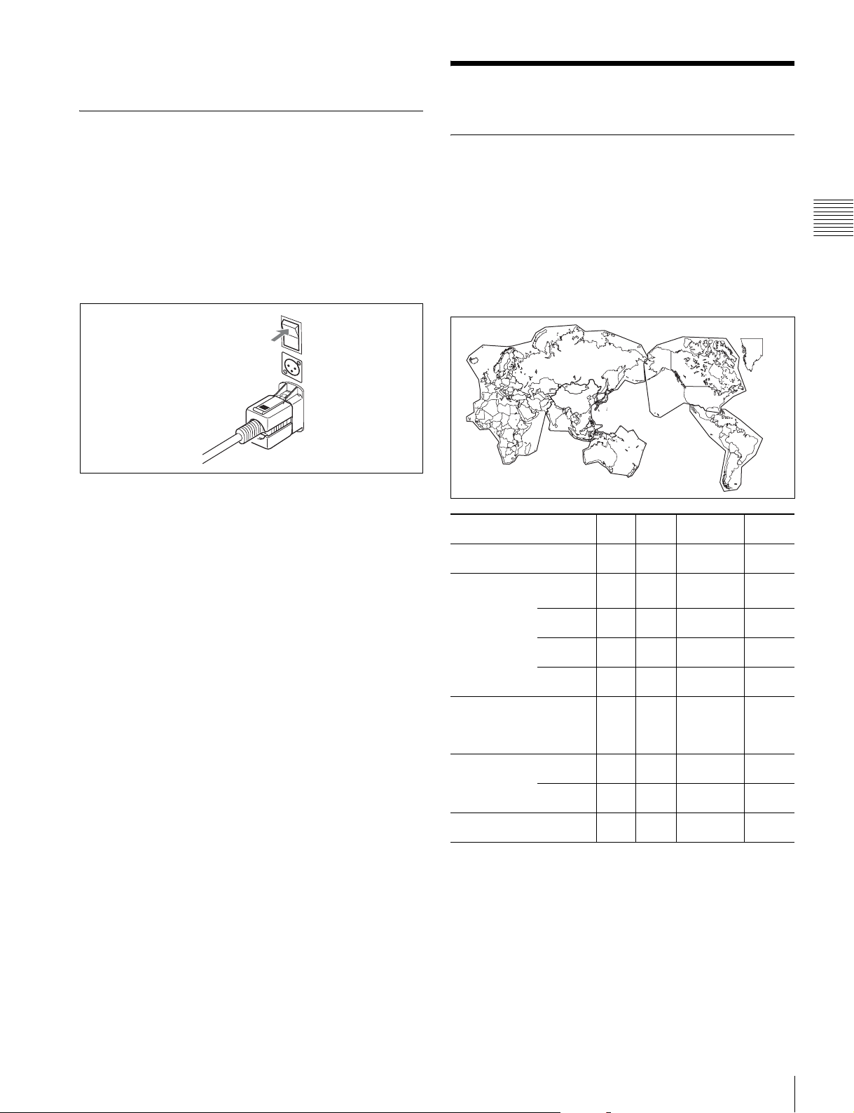
over the DC power supply. To use the DC power supply,
disconnect the AC power cord.
Turning on the Monitor
Press the MAIN POWER switch on the rear panel to turn
on the power.
When you turn on the monitor for the first time after
purchasing it, the Select Area screen is displayed. Select
the area where you intend to use this monitor.
For selecting the area, see page 33.
Settings
Selecting the Area
When you turn on the monitor for the first time after
purchasing it, select the area where you intend to use this
monitor from among the options.
When the area is selected, the menu item settings suitable
for the selected area are applied.
Default value for each area
3
Chapter 2 Preparations
The warm-up time is more than 30 minutes, approximately.
When the monitor is in standby mode
As the OPERATE lamp lights in red in standby mode,
press the MONITOR I/1 switch of the controller.
The OPERATE lamp lights in green and the monitor enters
operation mode.
5
1
4
3
1North America D65 7.5% Betacam
2Latin America
PAL& PAL-N
Area
NTSC&PALM Area
3Africa
Australasia
Europe
Middle-East
4Asia Except
Japan
5Japan D93 0%
Argentina D65 0%
Paraguay D65 0%
Uruguay D65 0%
Other Area D65 7.5% Betacam
NTSC Area D65 7.5% Betacam
PAL Area D65 0%
3
Color
Te mp
D65 0%
Setup
Level
2
Component
Level
SMPTE/
EBU-N10
SMPTE/
EBU-N10
SMPTE/
EBU-N10
SMPTE/
EBU-N10
SMPTE/
EBU-N10
SMPTE/
EBU-N10
Color
Profile
ITU-R
BT.709
ITU-R
BT.709
ITU-R
BT.709
ITU-R
BT.709
ITU-R
BT.709
ITU-R
BT.709
ITU-R
BT.709
ITU-R
BT.709
ITU-R
BT.709
Note on the setting of color temperature
If you measure the color temperatures of different display
types, such as CRT, LCD, or OLED, by using a common
(or general) color analyzer that is based on CIE 1931, and
adjust the xy chromaticity to the same value, the
appearance may be different because of optical spectrum
differences.
Settings
33
Page 34
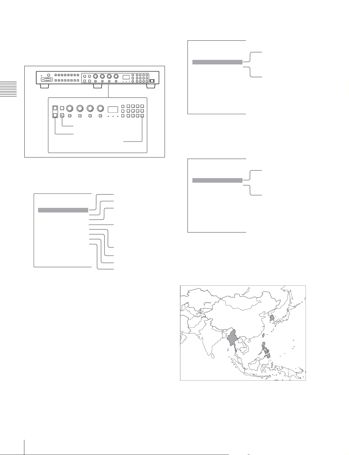
To compensate for this difference, the D93, D65, D61, D55
and User1 to User5 settings (except D-Cine) of the monitor
are adjusted by an offset*.
* The offset value applied (x-0.006, y-0.011) is based on the Judd’s function
to the CIE 1931 (x, y) value.
Chapter 2 Preparations
If 2 Latin America is selected:
Select Area
Latin America
PAL & PAL-N Area B
NTSC & PAL-M Area B
PAL&PAL-N area
NTSC&PAL-M area
ENTER button
UP/DOWN buttons
Ent button
1
Turn on the monitor with the MAIN POWER switch.
The Select Area screen appears.
1 North America
Select Area
North America B
Latin America B
Africa B
Australasia B
Europe B
Middle-East B
Asia Except Japan B
Japan B
2 Latin America
3 Africa
Australia/New Zealand
Europe/Russia
Middle East
4 Asia Except Japan
5 Japan
Select PAL & PAL-N or NTSC & PAL-M and press
the ENTER (Ent) button.
If 4 Asia Except Japan is selected:
Select Area
Asia Except Japan
NTSC Area B
PAL Area B
NTSC area
PAL area
Customers who will use this monitor in the shaded
areas shown in the map below should select NTSC
Area.
Other customers should select PAL Area.
Then press the ENTER (Ent) button.
34
2
Press the UP or DOWN button of the controller to
select the area where you intend to use the monitor and
press the ENTER (Ent) button.
If you select either Latin America or Asia Except
Japan, one of the following screens appears.
Settings
Page 35
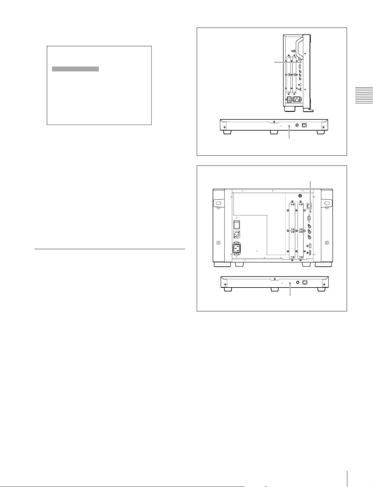
3
Confirm the settings.
Select Area
XXXXXXXXXX
Color Temp: xx
Setup Level: xx
Component Level: xx
Color Profile:
BVM-E250A
NETWORK switch
t Set to PEER TO
PEER.
xx
Cancel
Confirm
Cancel: Select to cancel the setting and return to the
Select Area screen.
Confirm: Select to save the setting and end selecting
the area.
See “Default value for each area” on page 33 on the
setting value.
After saving and reflecting the setting, you can change the
setting with the menu.
• Color Temp (color temperature) (page 60)
• Setup Level (NTSC Setup Level: page 64, Betacam
Setup Level: page 64)
• Component Level (page 64)
• Color Profile (page 61)
Setting for the LAN to Connect the Multiple Units
Controller
(BKM-16R)
BVM-E170A
Chapter 2 Preparations
NETWORK switch
tSet to PEER TO PEER.
NETWORK switch
t Set to PEER TO PEER.
You can control the multiple monitors using the controller
(BKM-16R, optional) connected via each LAN (10/100)
connector. You can also control a specific monitor or
monitor group.
Set an IP address to the monitors and the controller and a
monitor ID number and group ID number to each monitor.
1
Set the NETWORK switches of each monitor and the
controller to PEER TO PEER.
Controller
(BKM-16R)
2
Set the different IP address to each monitor and the
NETWORK switch
tSet to PEER TO PEER.
controller.
Monitor: Set the IP address in the Network Setting
menu (page 81) of the System Configuration menu.
Controller: Set the IP address in the Network Setting
menu (page 91) of the Controller menu.
3
Set Monitor ID and Group ID in the Network menu
(page 81) of the System Configuration menu.
Set the different monitor ID number to each monitor
and if necessary, group ID number.
You can use the numbers 1 to 99 as a monitor ID
number or group ID number.
4
Set the NETWORK switches of the monitor and the
controller to LAN.
Settings
35
Page 36
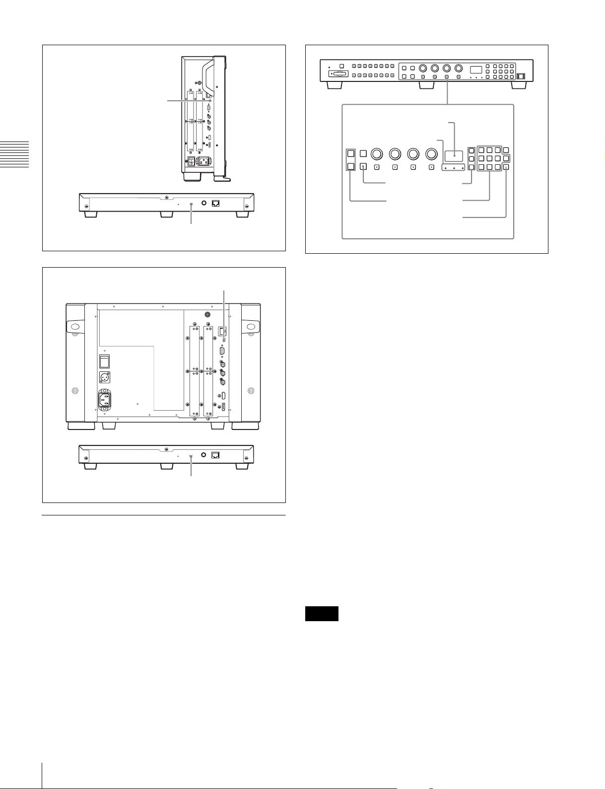
BVM-E250A
NETWORK switch
tSet to LAN.
Display window
Lamp
Chapter 2 Preparations
Controller
(BKM-16R)
BVM-E170A
NETWORK switch
tSet to LAN.
NETWORK switch
tSet to LAN.
3
2
1
2
3
1
Press the corresponding button to select the connection
mode.
SINGLE button: Selects single connection mode.
The designated monitor is connected remotely.
The monitor ID number is displayed on all connected
monitors when the button is held pressed.
GROUP button: Selects group connection mode.
The monitor of the designated group is connected
remotely.
The group ID number is displayed on all connected
monitors when the button is held pressed.
ALL button: Selects all connection mode.
All monitors are connected remotely.
The lamp corresponding the pressed button flashes and
lights after recognizing the monitor.
Controller
(BKM-16R)
NETWORK switch
tSet to LAN.
Selecting the Monitor (Designation of the Monitor or Group ID Number)
When the multiple monitors are connected by the network
connections, you can remotely connect the monitors from
the controller by designating the set monitor ID number or
group ID number.
2
Select the monitor ID number for the single connection
mode or group ID number for the group connection
mode by pressing the UP/DOWN or numeric button.
Up to 99 is entered as the monitor ID or group ID
number.
3
Press the ENTER or Ent button to confirm the setting.
The monitor ID number, group ID number or ALL is
displayed in the display window.
Notes
• When the monitor with no assigned monitor ID number
or group ID number is selected, the setting is not changed
and the previous connection status is maintained.
• When there are monitors with the same ID number, the
monitor with the lower IP address is selected.
• Even if a different monitor ID number is set to the
monitors, when the same IP address is set to another
monitor, the monitor cannot be connected to the network.
36
Settings
Page 37
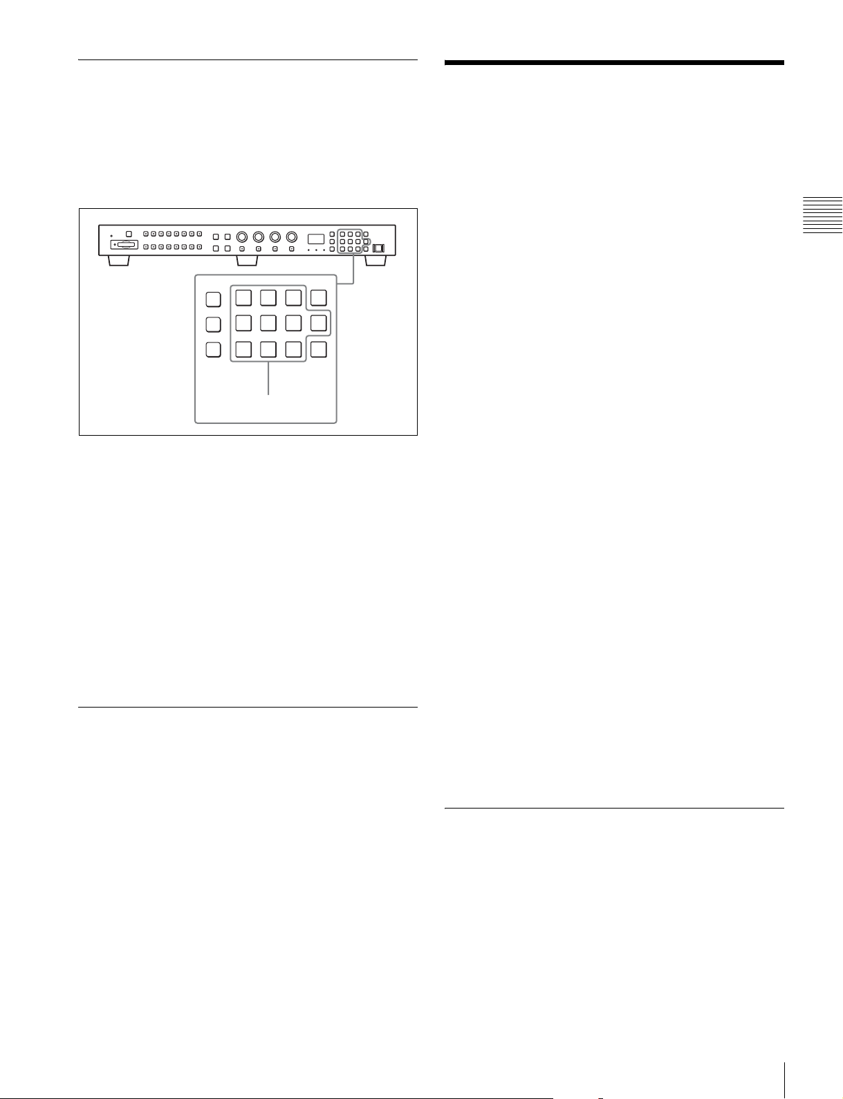
Assigning the Input Signal to the Channel
Adjusting
When you assign the input signal to the channel, you can
select the channel and change the input signal by pressing
the numeric button. The input signal is assigned to one of
channels 1 to 30.
1
1
Select the channel (CH1 to CH30) to be assigned by
pressing the numeric button of the controller.
To assign to a channel number from 1 to 9, press the
appropriate one-digit channel number on the numeric
keypad.
To assign to a channel number from 10 to 30, press the
0 button, then press the appropriate two-digit channel
number.
2
Set the input signal for the selected channel in Channel
Configuration menu (page 58).
The required setting is different due to the input signal
or picture quality to be displayed.
Setting the Display Mode of the Picture
Set the display mode condition of the input signal to
display on the screen. The setting items are following.
• Setting Matrix (transmission matrix)
• Selecting the color profile (color space and gamma)
Before adjusting
The monitor must be warmed up sufficiently.
To perform stable color reproduction, turn on the power of
the monitor, display the white signal and leave it in this
state for more than 30 minutes.
About monitor adjustment
The monitor is used as a measuring instrument and is
required to faithfully reproduce the input signal. To
measure the signal accurately, the monitor must be
calibrated correctly using a reference signal.
To calibrate, adjust the following items in sequence.
1 Chroma/phase adjustment
You can save the adjustment value in Preset1 to
Preset5 and Preset (D-Cine). The data of Preset1 to
Preset5 or Preset (D-Cine) is set to the channel in the
Picture Preset menu (page 61) of the Channel
Configuration menu.
Adjust the picture automatically with the auto chroma/
phase/matrix function for every signal format and
signal system to display the composite signal or Y/C
signal from the BKM-227W, or analog component
signal or analog RGB signal from the BKM-229X. If
the picture is not adjusted, the picture may not be
displayed correctly.
2 Color Temperature (white balance) adjustment
You can adjust the data set to the channel in the Color
Temp menu (page 60) of the Channel Configuration
menu.
You can adjust D93, D65, D61, D55, D-Cine or User1
to User5 except for the XYZ format signal and D-Cine
XYZ or User XYZ1 to User XYZ5 for the XYZ format
signal.
3 Brightness/Contrast adjustment
You can save the adjustment value in Preset1 to
Preset5 and Preset (D-Cine). The data of Preset1 to
Preset5 or Preset (D-Cine) is set to the channel in the
Picture Preset menu (page 61) of the Channel
Configuration menu.
Chroma/Phase Adjustment
Chapter 2 Preparations
1
Set Matrix in the Matrix menu (page 61) of the
Channel Configuration menu.
2
Select the color profile (color space and gamma) in the
Color Profile menu (page 61) of the Channel
Configuration menu.
Automatic adjustment (with auto chroma/phase/matrix
function) is required for each signal format, signal system
and matrix to display the composite or Y/C signal from the
BKM-227W, or the analog component or analog RGB
signal from the BKM-229X.
As you can automatically adjust the chroma, phase, matrix
and also 100% (white) and 0% (black) levels of the monitor
to the same as those of the reference signal by performing
Adjusting
37
Page 38
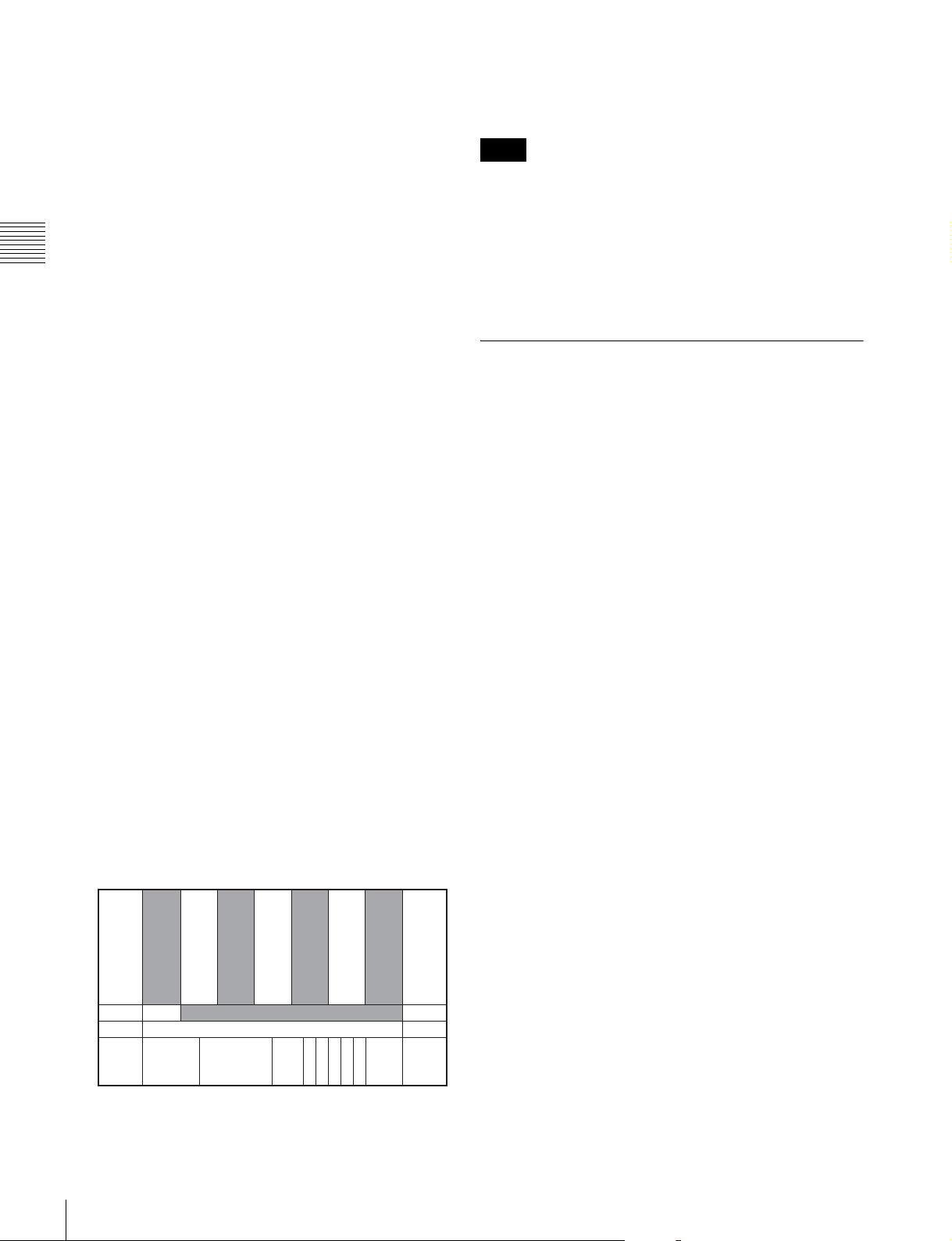
the automatic adjustment, the automatic adjustment is also
effective for the RGB signal.
Perform the manual adjustment of chroma and phase to
adjust them further after automatic adjustment or to adjust
the digital signal from the standard input, BKM-220D,
BKM-243HS, BKM-244CC or BKM-250TG.
Automatic adjustment (recommended)
1
Input the reference color-bar signal to the monitor.
Chapter 2 Preparations
2
Select Auto in the Picture Adj menu of the Adjustment
menu and perform the automatic adjustment of the
chroma, phase and matrix in Auto Adjust (page 51).
Manual adjustment
The following is the example of the method to perform the
manual adjustment of the chroma and phase.
1
Input the multi format color-bar signal or SMPTE
color-bar signal to the monitor.
2
Set the BLUE ONLY button to on.
Red and green signals are cut, and only the blue signal
is displayed as a monochrome picture.
The following is the example of the adjustment when the
multi format color-bar signal is used.
The adjusted data is confirmed.
6
Set the BLUE ONLY button to off.
Note
You can access manual adjustment without opening the
Adjustment menu. To access it, press the MANUAL button
located below the CHROMA or PHASE knob of the
controller. If manual adjustment is accessed by this
method, the adjusted value is common to all channels and
valid only when the lamp of the MANUAL button is lit. To
turn off the lamp of the MANUAL button, press the button
again.
Color Temperature (White Balance) Adjustment
This monitor is equipped with manual and automatic color
temperature adjustments.
BVM-E250A: The automatic color temperature
adjustments can be performed using a specified color
temperature probe.
BVM-E170A: The automatic color temperature
adjustments can be performed using the built-in color
sensor or a specified color temperature probe.
3
Select the Manual Adjust menu (page 52) in the Picture
Adj menu of the Adjustment menu.
4
Adjust the levels with the CHROMA or PHASE knob
of the controller while tracking so that the brightness of
bars “a” (75% White, Cyan, Magenta and Blue parts)
and “b” (75% White part) (in the following illustration)
are the same.
For the composite and Y/C signals
Adjust the levels with the CHROMA and PHASE
knob.
For the component signal
Adjust the levels with the CHROMA knob.
a (Cyan)
a (75% White)
b (75% White)
a (Magenta)
Special software is required for the automatic adjustment
using the specified probe. For details, contact your Sony
representative.
Automatic adjustment (using the built-in
color sensor) (for BVM-E170A only)
1
Select the Auto Adjust menu (page 55) in the Color
Temp Adj menu of the Adjustment menu.
Manual adjustment
1
Select the Manual menu (page 53) in the Color Temp
Adj menu of the Adjustment menu then select the
Manual Adjust menu.
2
Adjust the color in gain side with the PHASE,
a (Blue)
CHROMA, BRIGHT or CONTRAST knob.
3
Press the UP or DOWN button and adjust the color in
bias side with the PHASE, CHROMA, BRIGHT or
CONTRAST knob.
38
5
Press the ENTER or Ent button.
Adjusting
4
Press the UP or DOWN button.
5
Repeat steps 2 to 4 until the desired color is obtained,
because the gain and bias adjustments may affect each
other.
Page 39
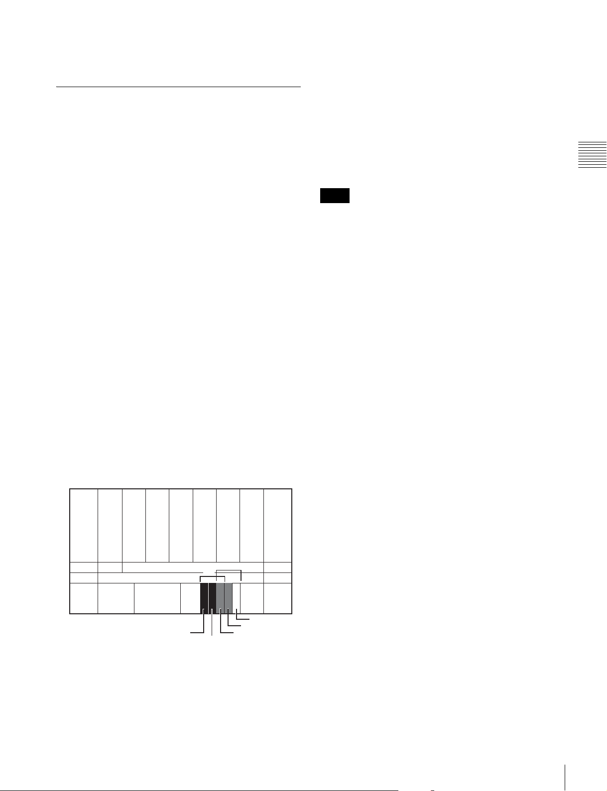
6
SD
Press the ENTER or Ent button.
The adjusted data are confirmed.
Brightness/Contrast Adjustment
We recommend adjusting the luminance to 100 [cd/
2
m
] when Preset1 to Preset5 is selected in the Picture
Preset menu of the Channel Configuration menu and to
48 [cd/m
Picture Preset menu of the Channel Configuration
menu.
2
] when Preset (D-Cine) is selected in the
As an image on a color video monitor is seen differently
according to the ambient light (environmental brightness),
adjust the brightness (black level) according to the ambient
light and the black level of the image to be reproduced and
adjust the contrast (white level) according to the ambient
light.
Adjust the brightness/contrast with an external reference
signal of a multi format color-bar signal or SMPTE colorbar signal.
1
Input the multi format color-bar signal or SMPTE
color-bar signal to the monitor.
The following are explained as the example when the
multi format color-bar signal is used for adjustment.
2
Select the Manual Adjust menu (page 52) in the Picture
Adj menu of the Adjustment menu.
3
Adjust the –2%, 0% and +2% ranges or the 0%, +2%
and +4% ranges of the PLUGE signal section of the
color-bar with the BRIGHT knob.
HD signal
Adjust so that the –2% and 0% ranges are seen as equal
and the +2% and 0% ranges are more distinctive.
5
As the brightness and contrast adjustments affect each
other, repeat the adjustments of step 3 and 4.
6
Press the ENTER or Ent button.
Note
You can access manual adjustment without opening the
Adjustment menu. To access it, press the MANUAL button
located below the BRIGHT or CONTRAST knob of the
controller. If manual adjustment is accessed by this
method, the adjusted value is common to all channels and
valid only when the lamp of the MANUAL button is lit. To
turn off the lamp of the MANUAL button, press the button
again.
Chapter 2 Preparations
SD signal
Adjust so that the 0% and +2% ranges are seen as equal
and the +2% and +4% ranges are more distinctive.
SD
SD
HD
+4%
0%
+2%-2%
0%
4
Adjust so that the luminance of the 100% white signal
of the color-bar is set to the desired value with the
CONTRAST knob.
Adjusting
39
Page 40
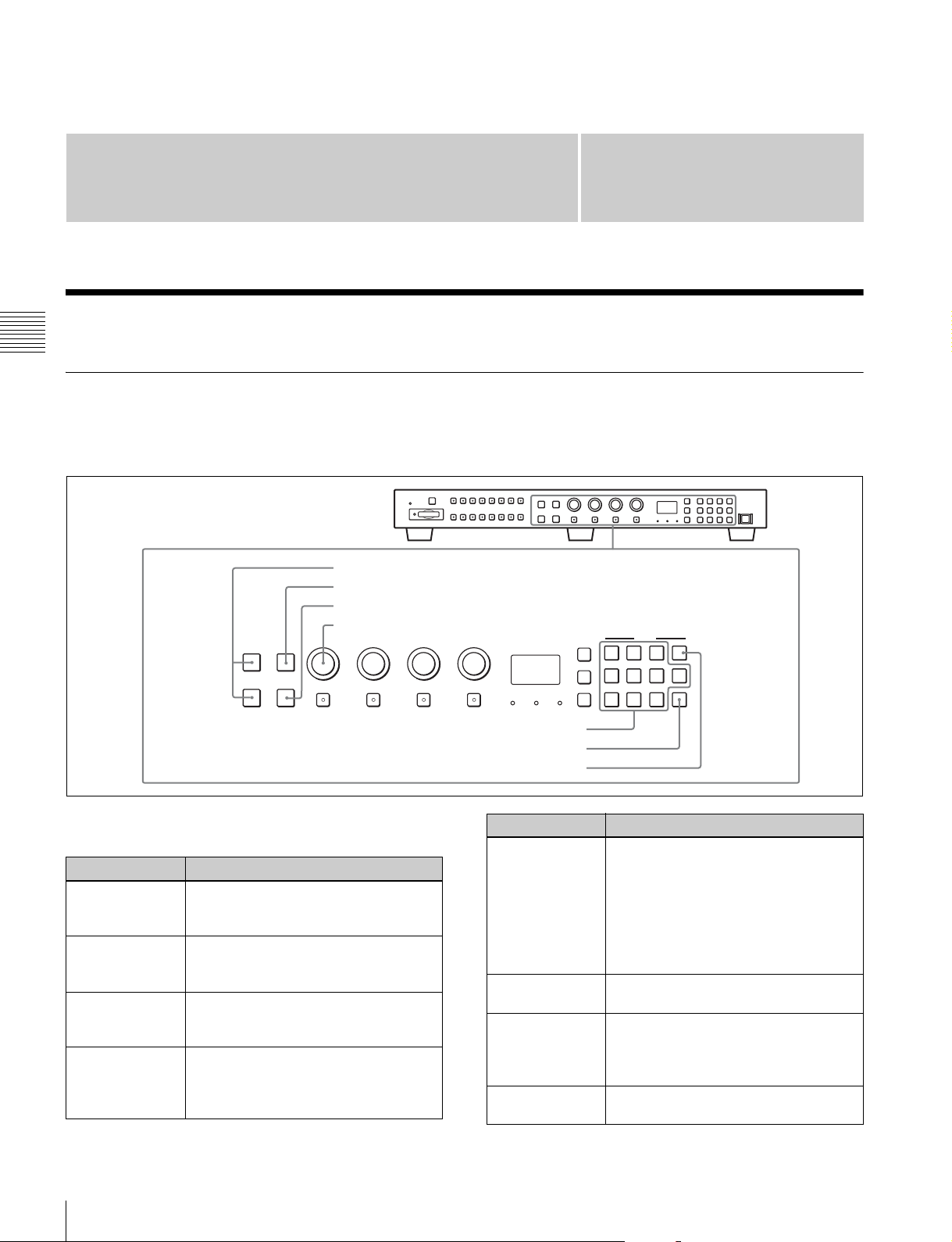
Menu
Basic Menu Operations
Chapter 3 Menu
Menu Operation Buttons
The menu is operated using the menu operation buttons on
the controller (BKM-16R, optional).
Controller (BKM-16R)
1 UP/DOWN buttons
2 MENU button
3 ENTER button
4 PHASE knob
CHROMA
UP MENU
DOWN
PHASE
ENTER
MANUAL MANUAL MANUAL MANUAL
BRIGHT
CONTRAST
SINGLE
GROUP ALL
Chapter
REMOTE
SINGLE
GROUP
ALL
INPUT
1
2
4
5
7
8
3
3
Del
0
6
Ent
9
The functions of the menu operation buttons are described
below.
Button Function
1 UP button
1 DOWN button
2 MENU button
3 ENTER
button
Moves the cursor upward. In setting
mode, increases the setting or adjustment
value.
Moves the cursor downward. In setting
mode, decreases the setting or
adjustment value.
Displays the menu. Goes back to the
menu of the upper level. (On the main
menu, goes back to the normal picture.)
Changes an item or displays the
information on the functions assigned to
function buttons. In setting mode,
confirms the adjustment or setting value.
5 Numeric buttons
6 Ent button
7 Del button
Button Function
4 PHASE knob
5 Numeric
buttons
6 Ent button
7 Del button
By turning this knob clockwise, the cursor
moves downward. In setting mode,
increases the setting or adjustment value
(has the same function as UP button).
By turning this knob counterclockwise, the
cursor moves upward. In setting mode,
decreases the setting or adjustment value
(has the same function as DOWN button).
Enters the numerical values.
Changes an item or displays the
information on the input signal, etc. In
setting mode, confirms the adjustment or
setting value.
Deletes the values and characters
entered.
Basic Menu Operations
40
Page 41
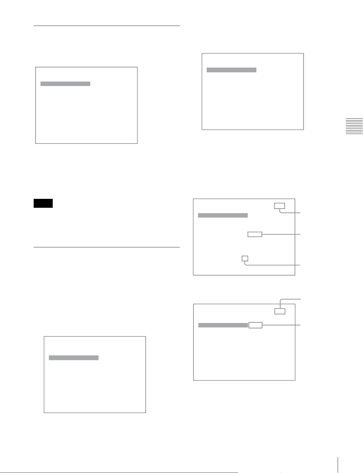
Displaying the Menu
Press the MENU button.
The main menu is displayed on the screen.
MENU
Adjustment B
Channel Configuration
Auxiliary Setting B
Function Setting B
System ConfigurationB
File Management B
System Status B
Controller B
Key Protect: xxx
When you select one item on the main menu, the level 1
menu of the selected item appears.
For the items on the menu, see “Menu Structure” on page
44.
B
The level 1 of the selected menu is displayed.
The current settings are displayed in place of the x
marks on the illustrations of the menu screen.
iChannel Configuration 1/3
CH01
Format B
Input Port: xxxxx
Input No: xxxxx
Screen Aspect B
Sync Mode: xxx
Color Temp: xxx
Picture Preset: xxxxx
Matrix B
Color Profile B
4
Repeat steps 2 and 3 until the desired menu is
v
V
displayed.
For more information about setting and adjustments,
see below.
Display example
Chapter 3 Menu
Notes
• The menu disappears automatically if not operated for
about one minute.
• Menu items displayed in gray cannot be selected.
• This menu is not displayed when Pixel Zoom is set to on.
Setting or Adjusting in the Menu Operation
1
Press the MENU button.
The main menu is displayed.
2
Using the UP or DOWN button or PHASE knob, select
the desired item. (Example: select the Channel
Configuration menu by pressing the DOWN button.)
MENU
Adjustment B
Channel Configuration
Auxiliary Setting B
Function Setting B
System ConfigurationB
File Management B
System Status B
Controller B
Key Protect: xxx
3
Press the ENTER or Ent button.
B
Indicates that
v
iChannel Configuration 1/3
CH01
Format B
Input Port: xxxxx
Input No: xxxxx
Screen Aspect B
Sync Mode: xxx
Color Temp: xxx
Picture Preset: xxxxx
Matrix B
Color Profile B
iChannel Configuration 2/3
CH01
Marker Preset: xxxxx
H Shift Offset: xxx
Channel Name B
NTSC Setup Level:: xx
Component Level: xxxxx
Betacam Setup Level::
RGB Range: B
1080I/PsF B
Film Cadence::
xxx
xxx
V
v
V
the menu
continues onto
next page.
Chooses the
setting value.
Indicates that
this item has
sub-list. You
can go to the
lower level.
Indicates that
the menu is
continued from
previous page.
Enters
numerical
values.
Choosing the setting value
The method for selecting the value is different due to the
menu item.
• Selecting in setting mode
• Selecting from the setting list
Basic Menu Operations
41
Page 42
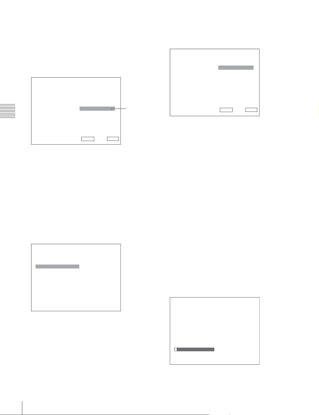
When selecting in setting mode
1
Using the UP or DOWN button or PHASE knob, select
the desired item and press the ENTER or Ent button.
The cursor moves to the setting value and the monitor
enters in setting mode.
Display example
Chapter 3 Menu
The cursor moves to the setting value and the monitor
enters in setting mode.
Display example
iChannel Configuration 1/3
CH01
Format B
Input Port: xxxxx
Input No: xxxxx
Screen Aspect B
Sync Mode: xxx
Color Temp: xxx
Picture Preset: xxxxx
Matrix B
Color Profile B
Set: ENTER Cancel: MENU
2
Using the UP or DOWN button or PHASE knob, select
v
V
Cursor
the setting value.
3
Press the ENTER or Ent button.
The setting is confirmed and the cursor returns to the
item.
iChannel Configuration 2/3
CH01
Marker Preset xxxxx
H Shift Offset: xxx
Channel Name B
NTSC Setup Level:: xx
Component Level: xxxxx
Betacam Setup Level::
RGB Range: B
1080I/PsF B
Film Cadence::
2
Select the value in one of the following three ways:
xxx
xxx
Set: ENTER Cancel: MENU
v
V
• Enter the value directly using the numeric buttons
and press the ENTER or Ent button. (only the item
whose the value of setting range is over 0)
• Select the value using the UP or DOWN button.
• Select the value using the PHASE knob.
3
Press the ENTER or Ent button.
The setting is confirmed and the cursor returns to the
item.
When selecting from the setting list
1
Using the UP or DOWN button or PHASE knob, select
the desired item in the setting list.
Display example
iiiParallel Remote 1/5
1 Pin
CH: 01
---
Under Scan
Over Scan
Native Scan
16 : 9
H Delay
V Delay
External Sync
Comb
2
Press the ENTER or Ent button.
v
V
The setting is confirmed and the display returns to the
menu of the upper level.
Entering characters
1
Using the UP or DOWN button or PHASE knob, select
New Name or the existing name.
The “---“ means that one or more characters can be
entered in sequence after the existing name.
2
Press the ENTER or Ent button.
3
Using the UP or DOWN button or PHASE knob, select
the characters that you wish to enter.
Display example
iiChannel Name
CH01
PROG___
EDIT___
CAM___
VTR___
PREV___
New Name
Entering numerical values
1
Using the UP or DOWN button or PHASE knob, select
the desired item and press the ENTER or Ent button.
Basic Menu Operations
42
Page 43
When you press the UP button or turn the PHASE knob
clockwise, the characters and symbols appear in the
sequence shown below.
Capital letters (A t B t ....... t Y t Z) t Lower-
case letters (a t b t ....... t y t z) t Numbers (0
t 1 t ....... t 8 t 9) t Marks t Capital
letters...
094: Five-step gray scale signal
095: Ramp signal
096: color-bar signal
097: 0% black signal
To cancel the internal signal, select one from the channel
numbers 1 to 30.
When you press the DOWN button or turn the PHASE
knob counterclockwise, the characters and symbols
appear in the reverse sequence described above.
The usable symbols are limited depending on the
menu.
“(space)” is not used as a first character of a sentence.
4
Press the ENTER or Ent button.
The selected character is entered.
Display example
iiChannel Name
CH01
PROG___
EDIT___
CAM___
VTR___
PREV___
New Name
C
Note
You cannot select channel numbers 91 to 97 in the
following cases:
• When the XYZ signal, or the computer signal of HDMI/
DisplayPort is input
• When Side by Side is set to On
• When Wipe is set to On
• When Butterfly is set to On
• When Blending is set to On
• When Pixel Zoom is set to on
Aborting Menu Operation
Press the MENU button. The menu of the upper level is
displayed.
When the MENU button is pressed in setting mode or
during adjustment, the menu returns to the previous setting.
The menu disappears automatically if not operated for
about one minute.
Chapter 3 Menu
5
Repeat steps 3 and 4 until all the characters are entered,
then press the ENTER or Ent button.
The selected characters are confirmed and the display
returns to the menu of the upper level.
To correct the entered character
Press the Del button. The character on the left side of the
cursor is deleted.
Entering the Channel Number
When selecting a one-digit number, press the button of the
channel number.
When selecting a two-digit number, first press the 0 button,
then press a two-digit channel number.
Channel numbers 91 to 97 assignment
The signal systems to which the internal signal is displayed
are assigned to channel numbers 91 to 97. The internal
signal of the last signal system is displayed.
091: PLUGE signal
092: 20% gray signal
093: 100% white signal
Basic Menu Operations
43
Page 44
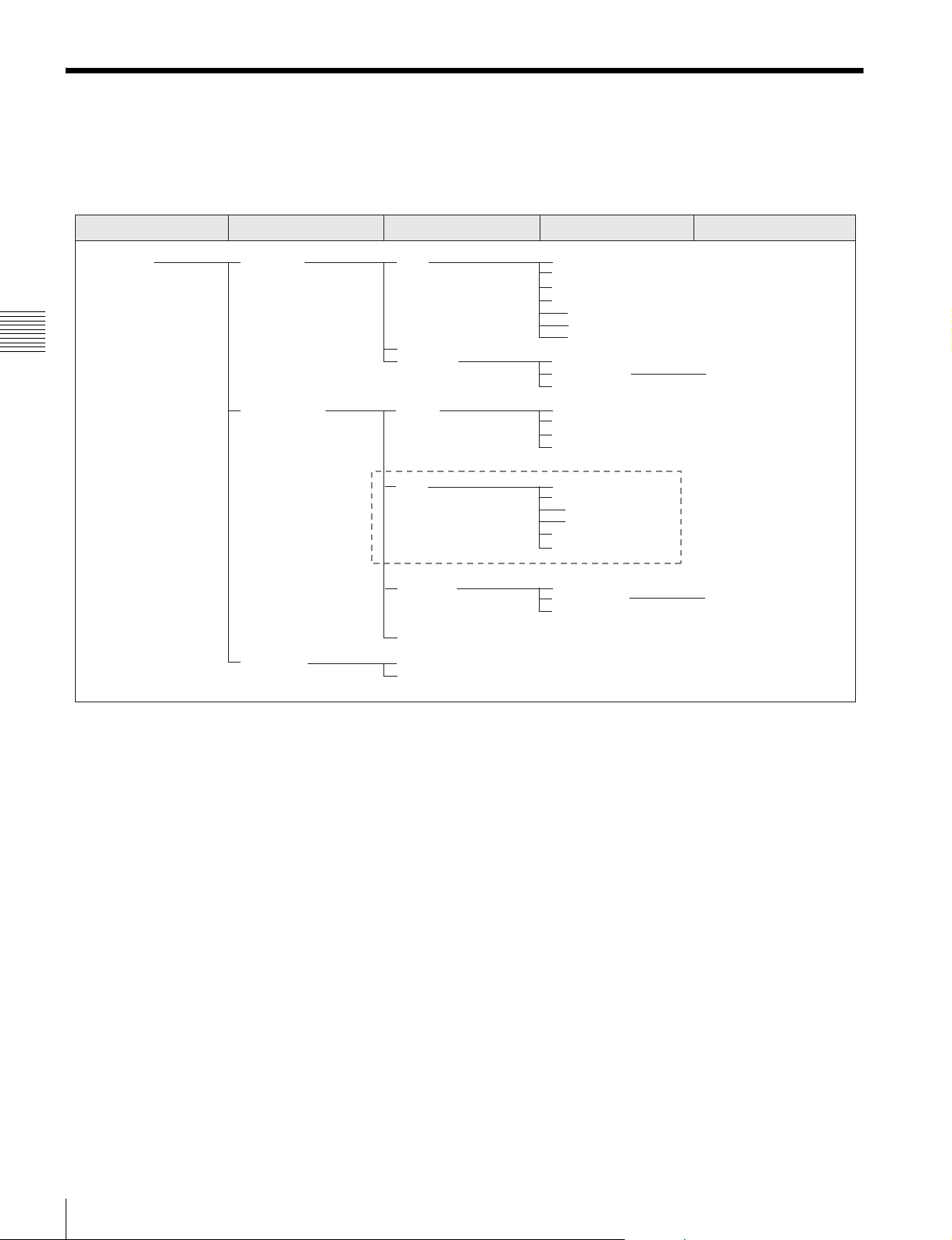
Menu Structure
For details of each menu, see the page in parentheses.
Adjustment menu (page 51)
Main menu Level 1 Level 2 Level 3 Level 4
Adjustment Picture Adj Auto Auto Adjust
Color Bar
Restore Factory Data
Status
Input Port
Format
Matrix
Chapter 3 Menu
Manual Adjust
Copy From Preset Value
Other Monitor Monitor ID
Memory Stick
Color Temp Adj Manual Manual Adjust
Original Value
Signal
Contrast/Bright Hold
Auto Auto Adjust
Target Color Temp
x
y
Target Luminance
Contrast/Bright Hold
1)
Copy From Preset Value
Other Monitor Monitor ID
Memory Stick
Restore Factory Data
Position Adj H Shift
V Shift
1) For BVM-E170A only
44
Menu Structure
Page 45
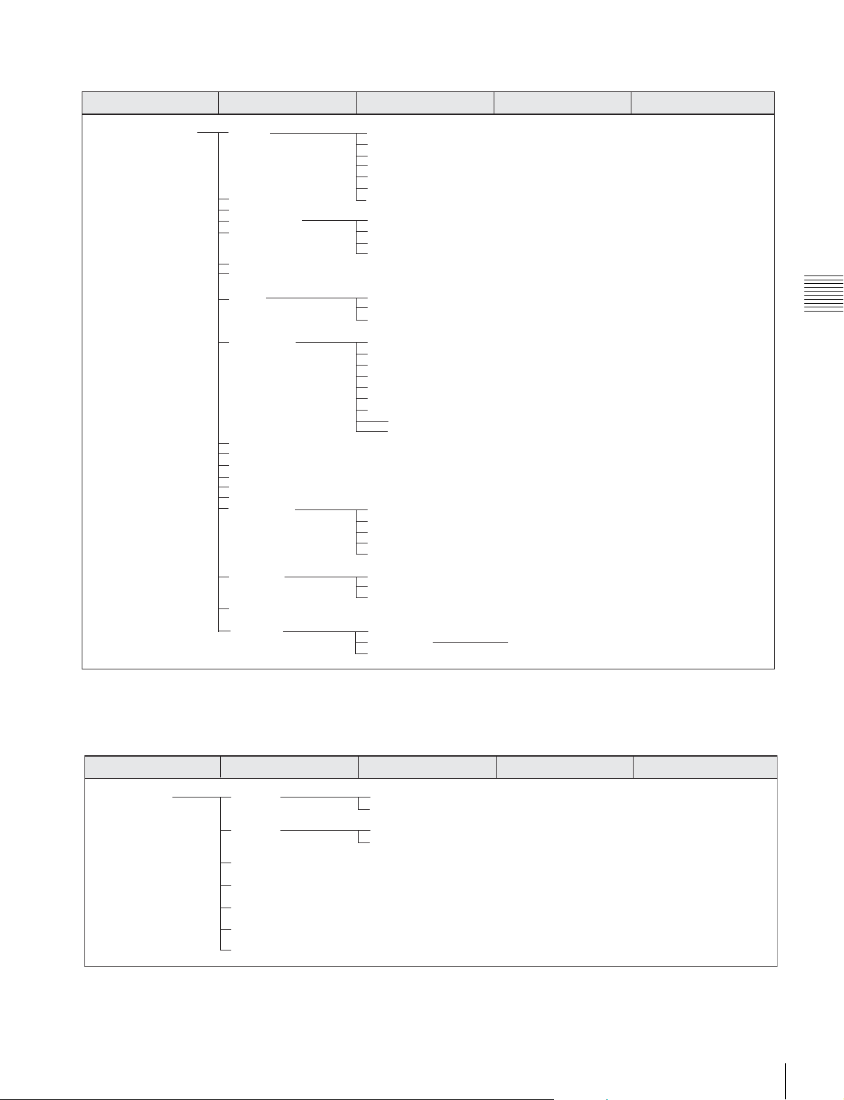
Channel Configuration menu (page 58)
Main menu Level 1 Level 2 Level 3 Level 4
Channel Configuration Format 3G/HD/SD-SDI
Dual Link HD-SDI
Composite
YC
Component
HDMI
Input Port DisplayPort
Input No
Screen Aspect HD
Sync Mode SD
DC 2048 × 1080
HDMI Auto
Color Temp
Picture Preset
Matrix HD
SD
HDMI/DisplayPort Auto
Color Profile Color Profile
Color Space
Gamma
ASC CDL
File
User LUT
File
Color Space
Gamma
Marker Preset
H Shift Offset
Channel Name
NTSC Setup Level
Component Level
Betacam Setup Level
RGB Range HD
DC 2048 × 1080
HDMI
DisplayPort
HDMI/DisplayPort Auto
1080I/PsF 24PsF
25PsF/50I
30PsF/60I
Film Cadence
Copy From Other CH
Other Monitor Monitor ID
Memory Stick
Chapter 3 Menu
Auxiliary Setting menu (page 67)
Main menu Level 1 Level 2 Level 3 Level 4
Auxiliary Setting ASC CDL Load ASC CDL
Delete ASC CDL
User LUT Load LUT
Delete LUT
Native Scan Mode
Aperture Value
NTSC Comb Filter
Filter Switch
Peak White Control
Menu Structure
45
Page 46
Function Setting menu (page 69)
Main menu Level 1 Level 2 Level 3 Level 4
Function Setting Marker Setting Aspect Marker Aspect Marker
Aspect Mode
Aspect
Line
Thickness
Color
Bright
Blanking
Area Marker 1 Area Marker 1
Aspect Mode
Aspect
Area Size
Width
Height
Mode
Chapter 3 Menu
Thickness
Color
Bright
Area Marker 2 Area Marker 2
Aspect Mode
Aspect
Area Size
Width
Height
Mode
Thickness
Color
Bright
Center Marker Center Marker
Mode
Color
Bright
H Position
V Position
Copy From Preset Value
Other Monitor Monitor ID
Memory Stick
P&P Setting Side by Side Line Display
Line Color
Line Bright
Wipe Line Display
Line Color
Line Bright
Position
Butterfly Line Display
Line Color
Line Bright
Position
Blending Blending Ratio
Pixel Zoom Setting Line Color
46
Menu Structure
Page 47
Main menu Level 1 Level 2 Level 3 Level 4
Gamut Error Display Gamut Error Display
OSD Notification
OSD Notification Reset
Input Detection Detection
Pixel Threshold
Signal Level
SDI YCbCr 10bit Upper Limit Y/Cb/Cr
Lower Limit Y/Cb/Cr
SDI RGB 10bit Upper Limit G/B/R
Lower Limit G/B/R
SDI YCbCr 12bit Upper Limit Y/Cb/Cr
Lower Limit Y/Cb/Cr
SDI RGB 12bit Upper Limit G/B/R
Lower Limit G/B/R
HDMI/DP YCbCr Upper Limit Y/Cb/Cr
Lower Limit Y/Cb/Cr
HDMI/DP RGB Upper Limit G/B/R
Lower Limit G/B/R
Post-Process Detection Detection
Pixel Threshold
Signal Level Upper Limit
Lower Limit
Zebra Pattern Line
Modulation
3D Setting Horopter Check Left
Right
Capture Load
Rename
Delete
Internal Signal
Function Switch Scan Mode
Native Scan
16:9
H Delay
V Delay
External Sync
Comb
Aperture
Mono
Blue Only
R Off
G Off
B Off
Chroma Up
Interlace
Marker
Aspect Marker
Area Marker 1
Area Marker 2
Center Marker
Aspect Marker-Line
Aspect Blanking-Half
Aspect Blanking-Black
Side by Side
Wipe
Butterfly
Blending
Error Notify Clear
Audio Level Meter
ALM Hold Reset
Time Code
Difference
Checkerboard
L/R Switch
Horopter Check
Flip H
Chapter 3 Menu
Menu Structure
47
Page 48
System Configuration menu (page 81)
Main menu Level 1 Level 2 Level 3 Level 4
System Configuration Network Monitor ID
Group ID
Network Setting IP Address
Subnet Mask
Default Gateway
Address
Protocol Setting SDCP/SDAP Community
SDCP Port No
SDAP Port No
SDAP Broadcast
SDAP Broadcast Period
Acceptable IP Address
Reset Protocol Setting
Parallel Remote Parallel Remote
Chapter 3 Menu
1 Pin - 8 Pin
Power Standby Mode
Power On Status
Default CH
On Screen Set Input Information Format
Position
CH No
Position
CH Name
Position
Scan Mode
Position
Closed Caption Closed Caption
Type
Service 708
Service 608
OSD Level
Audio Level Meter Audio CH
Position
Transparency
Peak Hold
Time Code VITC/LTC
Position
Level
Over Range
Password Change Password
Apply Password Adjustment
Channel Configuration
Auxiliary Setting
Function Setting
System Configuration
Individual Item Network
Parallel Remote
File Management Power
Controller On Screen Set
Key Protect Date/Time
Scan Mode Skip
Screen Saver
Date/Time
Scan Mode Skip
Screen Saver
Monitor Upgrade Software Upgrade
Kernel Upgrade
FPGA Upgrade
DisplayPort Upgrade
Maintenance
48
Menu Structure
Page 49
File Management menu (page 87)
Main menu Level 1 Level 2 Level 3 Level 4
File Management Save To Memory Stick
Copy From Other Monitor Monitor ID
Memory Stick
Delete Memory Stick
Data Maintenance Back Up System Data
Restore System Data
System Status menu (page 89)
Main menu Level 1 Level 2 Level 3 Level 4
Chapter 3 Menu
System Status CH Status
Serial No
SDI Payload ID Status Payload ID
Video Standard
Sampling Structure
Bit Depth
Picture Rate
Scanning Method
Link Number
Current Status
Format
I/PsF/P
HDMI/DP Status Pixel Encoding
Color Depth
Matrix
RGB Range
Model Name
Serial No
Software Version
Operation Time
Panel On Time
Network Switch
Controller Status Model Name
Serial No
Software Version
Network Switch
Port Status Option1-Option4
Model Name
Menu Structure
49
Page 50
Controller menu (page 91) / Key Protect menu (page 96)
Main menu Level 1 Level 2 Level 3 Level 4
Controller Network Network Setting IP Address
Subnet Mask
Default Gateway
Address
SNMP Setting Contact
Name
Location
Trap Mode
Trap Address Setting
Trap Address Status
Reset Mode/Address
Authentication
Community
Protocol Setting SDCP/SDAP Community
Chapter 3 Menu
SDCP Port No
SDAP Port No
SDAP Broadcast
SDAP Broadcast Period
Reset Protocol Setting
Function Key F1 - F16
Monitor ID Display
Controller Upgrade Software Upgrade
Kernel Upgrade
Key Protect
50
Menu Structure
Page 51
Adjustment Menu
Overview
Adjusts the picture, color temperature, etc.
When Adjustment is selected, the following menu is
displayed.
Note
This menu is not selectable in the following cases:
• When Side by Side is set to On
iAdjustment
Picture Adj B
Color Temp Adj B
Position Adj B
• When Wipe is set to On
• When Butterfly is set to On
• When Blending is set to On
Menu Function and Operation
Menu Function and operation ([ ]: factory setting)
Picture Adj Adjusts the chroma, phase, matrix and signal level automatically and contrast, brightness,
chroma and phase to set the preset value to picture adjustment preset data.
When the item is selected, the picture adjustment preset data to be set is displayed.
To change the picture adjustment preset data to be adjusted, you can select from Preset1,
Preset2, Preset3, Preset4, Preset5 and Preset (D-Cine) in the Picture Preset menu of the
Channel Configuration menu (page 58).
Auto Sets the automatic adjustment of chroma, phase, matrix and signal level.
When the item is selected, the selected preset data is displayed.
You can select this item when the composite or Y/C signal from the BKM-227W, or the analog
component or analog RGB signal from the BKM-229X is displayed.
Note
This menu is not selectable when the internal signal or captured frame is displayed.
Auto Adjust Starts automatic adjustment. (It may take some time until the automatic adjustment is
completed.)
An external color-bar signal for the reference is necessary for automatic adjustment (page
52).
The chroma data is reset to the default setting [1000].
The phase data is reset to the default setting [000].
Note
When the analog component signal or analog RGB signal is input, adjust the picture position
in the Position Adj menu (page 57) to perform the automatic adjustment in the Auto Adjust
menu. When the picture position does not fit, the adjustment will not be performed correctly
and this may cause a malfunction.
To cancel adjustment
Press the MENU button.
Chapter 3 Menu
Adjustment Menu
51
Page 52
Menu Function and operation ([ ]: factory setting)
Color Bar Sets the color-bar signal to input.
[Full Field 8]: 100% full-field 8-color bars (white, yellow, cyan, green, magenta, red, blue
and black)
Picture Adj
Restore Factory Data Resets the automatic adjustment data of chroma, phase, matrix and signal level to the default
Status Displays the status of the automatic adjustment data of the chroma, phase, matrix and signal
Chapter 3 Menu
Input Port Displays the input option port number of the automatic adjustment data to be adjusted.
Format Displays the signal format and signal system of the automatic adjustment data to be adjusted.
Matrix Displays the matrix of the automatic adjustment data to be adjusted.
Manual Adjust Adjusts values by turning the PHASE, CHROMA, BRIGHT, and/or CONTRAST knobs. After
Copy From Copies picture adjustment preset data.
Preset Value Copies other data in this monitor.
Other Monitor Copies data from another monitor.
Monitor ID Enter the ID number of the source monitor.
Memory Stick Copies data in the “Memory Stick”.
SMPTE: SMPTE standard color bars
EIA: EIA standard color bars (effective for 480/60i and 575/50i signals only)
Multi Format: Color bars standardized by SMPTE RP219/ARIB STD-B28
setting.
You cannot select this when the setting is the default value.
The following message appears.
Restore factory data?
OK: To reset the data, press the ENTER (Ent) button.
Cancel: To cancel, press the MENU button.
level to be adjusted.
Not Adjusted: Displays when the data is not adjusted.
Adjusted: Displays when the data is adjusted.
adjustment, press the ENTER (Ent) button to confirm the adjusted values.
Phase: –150 to +150 [000]
Chroma: 0000 to 2000 [1000]
Bright: –500 to +500 [000]
Contrast: 0000 to 2500 [1000] (for Preset1 to Preset5), [0480] (for Preset (D-Cine))
To display no characters on the screen while adjusting manually
Set the CHAR OFF button to on. The characters disappear. To display characters, set the
CHAR OFF button to off.
To reset the setting to the default
Press the corresponding MANUAL button. The adjusted value is reset to the default.
To cancel adjustment
Press the MENU button. The adjustment data is cleared.
To confirm adjustment
Press the ENTER (Ent) button.
Note
During adjustment, the screen saver is activated automatically if the operating conditions are
met, regardless of the setting of the screen saver function.
Notes
• Automatic adjustment data is not copied.
• Use the controller with software version 1.6 or higher to use the Copy From function.
When the item is selected, you can select from Preset1, Preset2, Preset3, Preset4, Preset5
or Preset (D-Cine).
When the NETWORK switch is set to PEER TO PEER, this is not selectable.
When the ID number is entered, you can select from Preset1, Preset2, Preset3, Preset4,
Preset5 or Preset (D-Cine).
When the item is selected, the file names in the source “Memory Stick” are displayed.
When the file is selected, you can select from Preset1, Preset2, Preset3
or Preset (D-Cine).
, Preset4, Preset5
52
Adjustment Menu
Page 53
Menu Function and operation ([ ]: factory setting)
Color Temp Adj Adjusts the color temperature.
When the item is selected, the color temperature data to be adjusted is displayed.
Except for the XYZ format signal
When D93, D65, D61, D55 or D-Cine data is changed, they are displayed as D93*, D65*,
D61*, D55* or D-Cine*.
To change the color temperature data to be adjusted, select D93, D65, D61, D55, D-Cine,
User1, User2, User3, User4 or User5 in the Color Temp menu of the Channel Configuration
menu.
For the XYZ format signal
When D-Cine XYZ data is changed, it is displayed as D-Cine XYZ*.
To change the color temperature data to be adjusted, select D-Cine XYZ, User XYZ1, User
XYZ2, User XYZ3, User XYZ4 or User XYZ5 in the Color Temp menu (page 60) of the
Channel Configuration menu.
Note
If you measure the color temperatures of different display types, such as CRT, LCD, or OLED,
by using a common (or general) color analyzer that is based on CIE 1931, and adjust the xy
chromaticity to the same value, the appearance may be different because of optical spectrum
differences.
To compensate for this difference, the D93, D65, D61, D55 and User1 to User5 settings
(except D-Cine) of the monitor are adjusted by an offset*.
* The offset value applied (x-0.006, y-0.011) is based on the Judd’s function to the CIE 1931 (x, y) value.
Manual Adjusts the color temperature manually.
When the item is selected, the color temperature data to be set is displayed.
Except for the XYZ format signal
When D93, D65, D61, D55 or D-Cine data is changed, they are displayed as D93*, D65*,
D61*, D55* or D-Cine*.
For the XYZ format signal
When D-Cine XYZ data is changed, it is displayed as D-Cine XYZ*.
When Contrast/Bright Hold is set to Off, the color temperature data are displayed. The
contrast data is displayed as the picture preset data Preset1 to Preset5 or Preset (D-Cine) set
in the Picture Preset menu of the Channel Configuration menu. To change the type of the
picture preset data, select from Preset1 to Preset5 or Preset (D-Cine) in the Picture Preset
menu (page 61) of the Channel Configuration menu.
Manual Adjust Adjusts the color temperature using the BRIGHT, CHROMA, PHASE and/or CONTRAST
knobs.
When the item is selected, the color temperature adjustment display appears, and the Red,
Green and/or Blue color temperature data to be adjusted are displayed to allow gain or bias
adjustment. Select gain or bias adjustment, using the UP/DOWN buttons.
The adjustable items and relevant knobs are as follows:
To adjust Red (red): BRIGHT knob
To adjust Green (green): CHROMA knob
To adjust Blue (blue): PHASE knob
To adjust brightness (Red, Green and Blue together): CONTRAST knob
Chapter 3 Menu
Adjustment Menu
53
Page 54
Menu Function and operation ([ ]: factory setting)
To hide the characters on the monitor during manual adjustment
Set the CHAR OFF button of the controller to on. As the characters on the display are
hidden, it becomes easy to adjust the picture. To display the characters, set the CHAR OFF
button to off.
To reset Red, Green and Blue to the value before adjustment
Color Temp Adj
Chapter 3 Menu
Original Value Sets the initial value.
Signal Sets the white signal to be used for adjustment.
Contrast/Bright Hold Sets the contrast and brightness to the adjusted value or the center value.
Auto (BVM-E170A only) Adjusts the color temperature automatically using the built-in color sensor.
During Red, Green and Blue adjustment, you can press the corresponding MANUAL button
to reset to the value before adjustment.
Pressing the MANUAL button of CONTRAST resets all Red, Green and Blue to the values
before adjustment.
Note
You cannot reset the setting after you press the ENTER (Ent) button, even if you press the
MANUAL button.
To cancel adjustment
Press the MENU button. The adjustment data is cleared and the setting returns to the
previous value.
To confirm adjustment
Press the ENTER (Ent) button.
Note
During adjustment, the screen saver is activated automatically if the operating conditions are
met, regardless of the setting of the screen saver function.
Except for the XYZ format signal
You can select from D93, D65, D61, D55, D-Cine, User1, User2, User3, User4 or User5.
When D93, D65, D61, D55 or D-Cine data is changed, they are displayed as D93*, D65*,
D61*, D55* or D-Cine*.
For the XYZ format signal
You can select from D-Cine XYZ, User XYZ1, User XYZ2, User XYZ3, User XYZ4 or User
XYZ5.
When D-Cine XYZ data is changed, it is displayed as D-Cine XYZ*.
[Internal]: Select when an internal signal is used. The signal is automatically switched
in synchronization with the gain and bias adjustments.
External: Select when an external input signal is used. Supply a signal to be used when
adjusting gain and bias.
Note
If Internal is selected for the XYZ format signal, the Calibration White signal is displayed.
Off: Sets contrast and brightness to the center values during and after color temperature
adjustment.
[On]: Retains the adjusted contrast and brightness values during and after color
temperature adjustment.
When this item is selected, the color temperature data to be adjusted is displayed.
Except for the XYZ format signal
When D93, D65, D61, D55 or D-Cine data is changed, they are displayed as D93*, D65*,
D61*, D55* or D-Cine*.
For the XYZ format signal
When D-Cine XYZ data is changed, it is displayed as D-Cine XYZ*.
When Contrast/Bright Hold is set to Off, the color temperature data are displayed. The
contrast data is displayed as the picture preset data Preset1 to Preset5 or Preset (D-Cine) set
in the Picture Preset menu of the Channel Configuration menu. To change the type of the
picture preset data, select from Preset1 to Preset5 or Preset (D-Cine) in the Picture Preset
menu (page 61) of the Channel Configuration menu.
54
Adjustment Menu
Page 55
Menu Function and operation ([ ]: factory setting)
Auto Adjust Starts adjustment.
When Auto Adjust is selected, not only the target color temperature but also other color
temperature data are adjusted.
Before automatic adjustment, select the value to use for the adjustment in following
Color Temp Adj
Target Color Temp Sets the adjustment value to be used from D93, D65, D61, D55, D-Cine or Any.
x Enters the CIE color system x coordinate.
y Enters the CIE color system y coordinate.
Target Luminance
Contrast/Bright Hold Sets the contrast and brightness to the adjusted value or the center value.
Copy From Copies the other color temperature.
sequence.
When you use the previously adjusted values for adjustment, select Auto Adjust in step 3 to
start adjustment without performing step 1 and step 2.
1 Select the color temperature to be used in Target Color Temp.
When Any is selected, enter the values of the CIE color system x and y coordinates.
2 Select Target Luminance and enter the value of the luminance (cd/m2) when the
100% white signal is input.
3 Select Auto Adjust.
The cursor appears and flashes at the bottom left of the screen.
(It may take some time until the automatic adjustment is completed.)
To cancel/stop the adjustment
Press the MENU button.
Note
Target Color Temp cannot be selected when the XYZ format signal is input. It is fixed to
Calibration White.
Set to 0.265 to 0.350.
Set to 0.270 to 0.360.
2
Enters the luminance (cd/m
brightness set to the center.
The following adjustable range is available, depending on the setting in the Picture Preset
menu.
Preset 1 to 5: 40 to 150 [100]
Preset (D-Cine): 20 to 72 [48]
Note
The calibrated luminance does not guarantee an absolute value and may be different from
the luminance detected by the probe.
The contrast value is fixed to 1000, and the brightness value is fixed to 000 during the
automatic adjustment.
Off: The contrast and brightness values are retained at the center value even after color
temperature adjustment.
[On]: The contrast and brightness values are returned to the previous values before
color temperature adjustment.
Note
Use the controller with software version 1.6 or higher to use the Copy From function.
) when the 100% white signal is input with the contrast and
Chapter 3 Menu
Adjustment Menu
55
Page 56
Menu Function and operation ([ ]: factory setting)
Preset Value Copies other data in this monitor.
Except for the XYZ format signal
When the item is selected, you can select from D93, D65, D61, D55, D-Cine, User1, User2,
User3, User4 or User5.
D93: Copies the color temperature of D93.
Color Temp Adj
Chapter 3 Menu
Other Monitor Copies data from another monitor.
Monitor ID Enter the ID number of the source monitor.
Memory Stick Copies data in the “Memory Stick”.
D65: Copies the color temperature of D65.
D61: Copies the color temperature of D61.
D55: Copies the color temperature of D55.
D-Cine: Copies the color temperature of D-Cine.
User1 to 5: Copies the color temperature of User1 to 5.
When D93, D65, D61, D55 or D-Cine data is changed, they are displayed as D93*, D65*,
D61*, D55* or D-Cine*.
For the XYZ format signal
When the item is selected, you can select from D-Cine XYZ, User XYZ1, User XYZ2, User
XYZ3, User XYZ4 or User XYZ5.
D-Cine XYZ: Copies the color temperature of D-Cine XYZ.
User XYZ1 to 5: Copies the color temperature of User XYZ1 to 5.
When D-Cine XYZ data is changed, it is displayed as D-Cine XYZ*.
When the NETWORK switch is set to PEER TO PEER, this is not selectable.
Except for the XYZ format signal
When the ID number is entered, you can select from D93, D65, D61, D55, D-Cine, User1,
User2, User3, User4 or User5.
D93: Copies the color temperature of D93.
D65: Copies the color temperature of D65.
D61: Copies the color temperature of D61.
D55: Copies the color temperature of D55.
D-Cine: Copies the color temperature of D-Cine.
User1 to 5: Copies the color temperature of User1 to 5.
When D93, D65, D61, D55 or D-Cine data is changed, they are displayed as D93*, D65*,
D61*, D55* or D-Cine*.
For the XYZ format signal
When the ID number is entered, you can select from D-Cine XYZ, User XYZ1,
User XYZ3, User XYZ4 or User XYZ5.
D-Cine XYZ: Copies the color temperature of D-Cine XYZ.
User XYZ1 to 5: Copies the color temperature of User XYZ1 to 5.
When D-Cine XYZ data is changed, it is displayed as D-Cine XYZ*.
When the item is selected, the file names in the source “Memory Stick” are displayed.
Except for the XYZ format signal
When the file is selected, you can select from D93, D65, D61, D55, D-Cine, User1, User2,
User3, User4 or User5.
D93: Copies the color temperature of D93.
D65: Copies the color temperature of D65.
D61: Copies the color temperature of D61.
D55: Copies the color temperature of D55.
D-Cine: Copies the color temperature of D-Cine.
User1 to 5: Copies the color temperature of User1 to 5.
When D93, D65, D61, D55 or D-Cine data is changed, they are displayed as D93*, D65*,
D61*, D55* or D-Cine*.
For the XYZ format signal
When the file is selected, you can select from D-Cine XYZ, User XYZ1, User XYZ2, User
XYZ3, User XYZ4 or User XYZ5.
D-Cine XYZ: Copies the color temperature of D-Cine XYZ.
User XYZ1 to 5: Copies the color temperature of User XYZ1 to 5.
When D-Cine XYZ data is changed, it is displayed as D-Cine XYZ*.
User XYZ2,
56
Adjustment Menu
Page 57
Menu Function and operation ([ ]: factory setting)
Restore Factory Data Resets the color temperature to the default setting.
You cannot select this when the setting is the default value.
The following message appears to confirm the data reset operation.
Restore factory data?
OK: To reset the data, press the ENTER (Ent) button.
Color Temp Adj
Position Adj Adjusts the position of the picture when the analog signal is input.
H Shift Adjusts the horizontal position of the picture.
V Shift Adjusts the vertical position of the picture.
Cancel: To cancel, press the MENU button.
When the item is selected, the signal system to be set is displayed.
You can select the item when the composite or Y/C signal from the BKM-227W, or the analog
component or analog component RGB signal from the BKM-229X is displayed.
To hide the characters on the monitor during adjustment
Set the CHAR OFF button of the controller to on. As the characters on the display are
hidden, it becomes easy to adjust the picture. To display the characters, set the CHAR OFF
button to off.
Note
This menu is not selectable when the internal signal or captured frame is displayed.
As the setting increases, the picture moves to the right, and as the setting decreases, the
picture moves to the left. [000]
Set in the H Shift Offset menu (page 64) of the Channel Configuration menu when the
difference of the horizontal position is necessary to adjust for different input signals of the
same signal system, etc.
As the setting increases, the picture moves up, and as the setting decreases, the picture
moves down. [000]
Chapter 3 Menu
Adjustment Menu
57
Page 58
Channel Configuration Menu
Overview
This menu is used for pertaining data to the input signals.
When Channel Configuration is selected, the following menus are displayed.
iChannel Configuration 1/3
CH01
Format B
Input Port: xxxxx
Input No: xxxxx
Screen Aspect B
Chapter 3 Menu
Sync Mode: xxx
Color Temp: xxx
Picture Preset: xxxxx
Matrix B
Color Profile B
v
V
iChannel Configuration 2/3
CH01
Marker Preset: xxxxx
H Shift Offset: xxx
Channel Name B
NTSC Setup Level:: xx
Component Level: xxxxx
Betacam Setup Level::
RGB Range: B
1080I/PsF B
Film Cadence::
The current channel is displayed. Perform the input setting
for the selected channel.
xxx
xxx
Note
v
V
This menu is not selectable in the following cases:
Before setting
Set the input signal for each channel. A channel number (1
to 30) is entered with the numeric buttons (page 43).
• When Side by Side is set to On
• When Wipe is set to On
• When Butterfly is set to On
• When Blending is set to On
Menu Function and Operation
Menu Function and operation ([ ]: factory setting)
Format Sets the input signal type.
Note
The default setting is 3G/HD/SD-SDI Auto.
3G/HD/SD-SDI Sets the serial digital signal format (Single-link 3G-SDI, HD-SDI or SD-SDI).
3G/HD/SD-SDI Auto: Changes the format automatically according to the Sampling
Structure, Bit Depth, Picture and transport scanning method information for Payload ID
of SMPTE-352M standard superimposed on the input signals.
Note
You can confirm the Payload ID information and the signal format status of the current
monitor in “SDI Payload ID Status” (page 90) of the System Status menu or using the
Status button on the controller.
For details on the display using the Status button, see “Displaying the Monitor Status
Page” (page 108).
3G-SDI: Sets the signal format.
4:2:2 YCbCr 10bit
4:4:4 YCbCr 10bit
4:4:4 RGB 10bit
4:4:4 YCbCr 12bit
4:4:4 RGB 12bit
4:4:4 XYZ 12bit
HD/SD-SDI Auto: Changes the format automatically according to the format of the input
signal.
SD-SDI
iChannel Configuration 3/3
CH01
Copy From B
v
V
Channel Configuration Menu
58
Page 59
Menu Function and operation ([ ]: factory setting)
Dual Link HD-SDI Sets the Dual-link HD-SDI signal format when two BKM-243HS or BKM-244CC are installed
in the OPTION 1 and 2 or OPTION 3 and 4 option ports or BKM-250TG is installed.
Format
Composite Sets the composite signal format when BKM-227W is installed.
YC Sets the Y/C signal format when BKM-227W is installed.
Component Sets the analog component signal format or analog RGB signal format when BKM-229X is
HDMI Sets the HDMI signal format.
DisplayPort Sets the DisplayPort signal format.
Input Port Enters the input port number.
4:2:2 YCbCr 10bit
4:4:4 YCbCr 10bit
4:4:4 RGB 10bit
4:4:4 YCbCr 12bit
4:4:4 RGB 12bit
4:4:4 XYZ 12bit
Auto: Changes automatically according to the format of the input signal.
It will take a few seconds to detect the format of an input signal. It is recommended that
a particular format be selected if it is determined.
NTSC
PAL
PAL-M
SECAM
Auto: Changes automatically according to the format of the input signal.
It will take a few seconds to detect the format of an input signal. It is recommended that
a particular format be selected if it is determined.
NTSC
PAL
PAL-M
SECAM
installed.
You can select from YPbPr or RGB.
In this manual, the 800 × 600, 1024 × 768, 1280 × 960, 1280 × 1024 and 1400 × 1050 signals
are referred to as the HDMI computer signals.
For the signal format to be displayed, see page 130.
In this manual, the 800 × 600, 1024 × 768, 1280 × 960, 1280 × 1024 and 1400 × 1050 signals
are referred to as the DisplayPort computer signals.
For the signal format to be displayed, see page 130.
You can select from [Standard], Option1 to Option4, Option1&2 or Option3&4.
Standard
When using the standard SDI input of the monitor
• When Format is set to 3G/HD/SD-SDI Auto or 4:2:2 YCbCr 10bit, 4:4:4 YCbCr 10bit,
4:4:4 RGB 10bit, 4:4:4 YCbCr 12bit, 4:4:4 RGB 12bit or 4:4:4 XYZ 12bit of 3G-SDI
• When Format is set to HD/SD-SDI Auto
• When Format is set to SD-SDI
Option1 to Option4
When the signal is input from the input adaptor installed to the option port
• When the BKM-250TG is installed and Format is set to 3G/HD/SD-SDI Auto or 4:2:2
YCbCr 10bit, 4:4:4 YCbCr 10bit, 4:4:4 RGB 10bit, 4:4:4 YCbCr 12bit, 4:4:4 RGB 12bit or
4:4:4 XYZ 12bit of 3G-SDI
• When the BKM-243HS, BKM-244CC or BKM-250TG is installed and Format is set to HD/
SD-SDI Auto
• When the BKM-220D, BKM-243HS, BKM-244CC or BKM-250TG is installed and Format
is set to SD-SDI
• When the BKM-227W is installed and Format is set to Composite Auto, Composite
NTSC, Composite PAL, Composite PAL-M, Composite SECAM, YC Auto, YC NTSC, YC
PAL , Y C PA L -M or Y C S E CA M
• When the BKM-229X is installed and Format is set to Component YPbPr or Component
RGB
Chapter 3 Menu
Channel Configuration Menu
59
Page 60
Menu Function and operation ([ ]: factory setting)
Option1&2, Option3&4
• When two BKM-243HS or BKM-244CC are installed in the OPTION 1 and 2 or OPTION
3 and 4 option ports and Format is set to 4:2:2 YCbCr 10bit, 4:4:4 YCbCr 10bit, 4:4:4
Input Port
Input No Enters the input connector number if there are two inputs with the same type of input
Chapter 3 Menu
Screen Aspect Selects the aspect ratio.
HD Sets the aspect ratio of the HD signal.
SD Sets the aspect ratio of the SD signal.
DC 2048 × 1080 Sets the aspect ratio of the digital cinema signal (2048 × 1080).
HDMI Auto Sets the manual or automatic setting for the aspect ratio of the HDMI signal.
Sync Mode Sets the sync signal when the analog component signal or analog RGB signal is input.
Color Temp Sets the color temperature.
RGB 10bit, 4:4:4 YCbCr 12bit, 4:4:4 RGB 12bit or 4:4:4 XYZ 12bit of Dual Link HD-SDI
Note
When the setting of Format and the installed adaptor do not match, the setting value may not
be changed. Set the Format correctly according to the installed adaptor.
connectors.
You can select from [Input 1] or Input 2 in the following cases:
• When the standard SDI input is selected (when Input Port is set to Standard)
• When the BKM-250TG is installed and Format is set to 3G/HD/SD-SDI Auto or 4:2:2
YCbCr 10bit, 4:4:4 YCbCr 10bit, 4:4:4 RGB 10bit, 4:4:4 YCbCr 12bit, 4:4:4 RGB 12bit or
4:4:4 XYZ 12bit of 3G-SDI
• When the BKM-243HS, BKM-244CC or BKM-250TG is installed and Format is set to HD/
SD-SDI Auto
• When the BKM-220D, BKM-243HS, BKM-244CC or BKM-250TG is installed and Format
is set to SD-SDI
• When two BKM-243HS or BKM-244CC are installed in the OPTION 1 and 2 or OPTION
3 and 4 option slots and Format is set to 4:2:2 YCbCr 10bit, 4:4:4 YCbCr 10bit, 4:4:4
RGB 10bit, 4:4:4 YCbCr 12bit, 4:4:4 RGB 12bit or 4:4:4 XYZ 12bit of Dual Link HD-SDI
Note
When the setting of Format or Input Port and the installed adaptor do not match, the setting
value may not be changed. Set Format or Input Port correctly according to the installed
adaptor.
You can select from [16:9] or 2.39:1.
You can select from [16:9] or 4:3.
You can select from [1.896:1] or 2.39:1.
Off: Select to set the aspect ratio manually with the controller, etc.
[On]: Select to set the aspect ratio automatically according to the input signal. The
aspect ratio is not set with the controller, etc.
You can select when Format is set to Component YPbPr or Component RGB.
[Internal]: Select when an internal sync signal is used.
External: Select when an external sync signal is used.
Except for the XYZ format signal
You can select from D93, D65, D61, D55, D-Cine, User1 to User5.
When D-Cine is selected, the color temperature is set to x=0.314 and y=0.351 in the CIE
chromaticity coordinate.
When D93, D65, D61, D55 or D-Cine data is changed, they are displayed as D93*, D65*,
D61*, D55* or D-Cine*.
For the XYZ format signal
You can select from D-Cine XYZ or User XYZ1 to User XYZ5.
When D-Cine XYZ data is changed, it is displayed as D-Cine XYZ*.
Note on color temperature adjustment
If you measure the color temperatures of different display types, such as CRT, LCD, or OLED,
by using a common (or general) color analyzer that is based on CIE 1931, and adjust the xy
chromaticity to the same value, the appearance may be different because of optical spectrum
differences.
To compensate for this difference, the D93, D65, D61, D55 and User1 to User5 settings
(except D-Cine) of the monitor are adjusted by an offset*.
* The offset value applied (x-0.006, y-0.011) is based on the Judd’s function to the CIE 1931 (x, y) value.
Channel Configuration Menu
60
Page 61
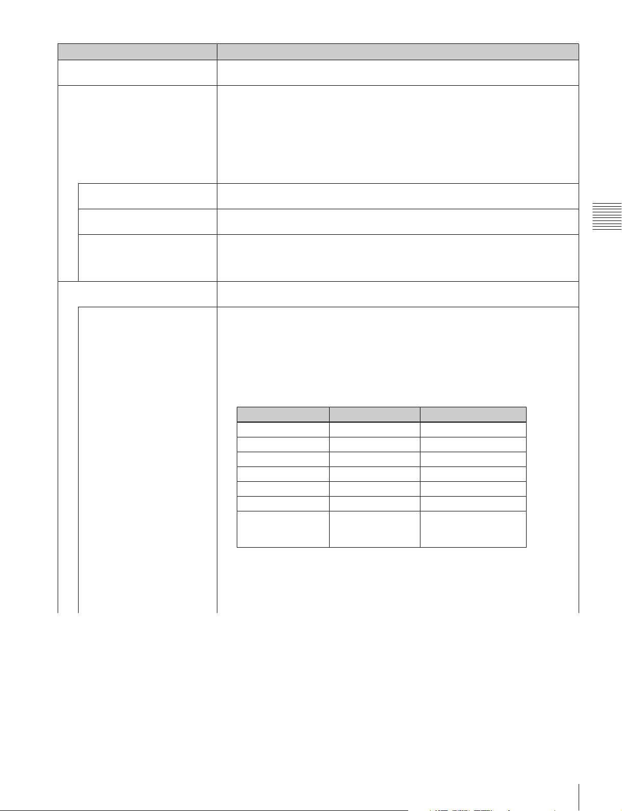
Menu Function and operation ([ ]: factory setting)
Picture Preset Sets the picture adjustment preset.
Select from Preset1 to Preset5 or Preset (D-Cine).
Matrix Sets Matrix data (transmission matrix) depending on the input signal format.
Three transmission matrix data are preset.
Matrix data
ITU-R BT.709: Select when the signal of the ITU-R BT.709 standards format is input.
ITU-R BT.601: Select when the signal of the ITU-R BT.601 standards format is input.
SMPTE 240M: Select when the signal of the SMPTE 240M standards format is input.
The Matrix data can be selected for the HD or SD input signal, respectively.
For the type of the input signal, see “Available Signal Formats” (page 124).
HD Sets Matrix of the HD signal.
You can select from [ITU-R BT.709], ITU-R BT.601 or SMPTE 240M.
SD Sets Matrix of the SD signal.
You can select from ITU-R BT.709, [ITU-R BT.601], SMPTE 240M.
HDMI/DisplayPort Auto Sets the manual or automatic setting for the transmission matrix of the HDMI or DisplayPort
signal.
Off: Select to use Matrix set in the HD or SD menu.
[On]: Select to set Matrix automatically according to the input signal.
Color Profile As the monitor is equipped with a wider color space OLED panel, the signal can be displayed
with the color space and gamma selected in the Color Profile menu.
Color Profile (BVM-E250A) Sets the color profile (color space and gamma) to be used.
There are six Color Profile data items in which the color space and gamma have been preset
and user channel data item in which Color Space (color space) and Gamma (gamma) can be
selected for each individual channel.
Chapter 3 Menu
Preset data: BVM SMPTE-C, BVM EBU, ITU-R BT.709, D-Cine, E250 Native, SGAMUT/S-LOG
Selectable data: User CHXX (the currently selected channel number is displayed)
Color Profile Color Space Gamma
BVM SMPTE-C SMPTE-C CRT BVM
BVM EBU EBU CRT BVM
ITU-R BT.709 ITU-R BT.709 2.4
D-Cine D-Cine 2.6
E250 Native E250 Native 2.2
S-GAMUT/S-LOG S-GAMUT S-LOG Standard
User CHXX Select above six
types in Color Space
menu (page 63)
Notes
• When setting CRT BVM gamma data for User CHXX, first select SMPTE-C or EBU in
the Color Space menu.
• The Gamma setting is fixed at 2.6 when an XYZ format signal is input.
• Set the Color Space menu to D-Cine when an XYZ format signal is input.
Select above six types in
Gamma menu (page 63)
Channel Configuration Menu
61
Page 62
Menu Function and operation ([ ]: factory setting)
Color Profile data
BVM SMPTE-C: Displays with the color space and gamma of BVM SMPTE-C phosphor
CRT.
BVM EBU: Displays with the color space and gamma of BVM EBU phosphor CRT.
Color Profile
Chapter 3 Menu
Color Profile (BVM-E170A) Sets the color profile (color space and gamma) to be used.
ITU-R BT.709: Displays with the color space of three primary color chromaticity points
provided by ITU-R BT.709 and gamma 2.4.
1)
D-Cine
provided by SMPTE RP 431-2.
E250 Native: Displays with the color space of the BVM-E250A individual three primary
color chromaticity points. This is the widest color space setting of the signal reproduced
by the BVM-E250A.
S-GAMUT/S-LOG: Displays with the color space of the transmission gamma S-LOG and
the wide color space mode S-GAMUT, which is available for the output signal of F23 or
F35 Digital Cinematography Camera.
User CHXX: Select when the color space and gamma are to be set individually
depending on the currently selected channel.
1) Three primary color chromaticity points provided by SMPTE RP 431-2 are not covered in full.
There are six Color Profile data items in which the color space and gamma have been preset
and user channel data item in which Color Space (color space) and Gamma (gamma) can be
selected for each individual channel.
Preset data: BVM SMPTE-C, BVM EBU, ITU-R BT.709, D-Cine, E170 Native, SGAMUT/S-LOG
Selectable data: User CHXX (the currently selected channel number is displayed)
: Displays with the color space of three primary color chromaticity points
Color Profile Color Space Gamma
BVM SMPTE-C SMPTE-C CRT BVM
BVM EBU EBU CRT BVM
ITU-R BT.709 ITU-R BT.709 2.4
D-Cine D-Cine 2.6
E170 Native E170 Native 2.2
S-GAMUT/S-LOG S-GAMUT S-LOG Standard
User CHXX Select above six
types in Color Space
menu (page 63)
Notes
• When setting CRT BVM gamma data for User CHXX, first select SMPTE-C or EBU in
the Color Space menu.
• The Gamma setting is fixed at 2.6 when an XYZ format signal is input.
• Set the Color Space menu to D-Cine when an XYZ format signal is input.
Color Profile data
BVM SMPTE-C: Displays with the color space and gamma of BVM SMPTE-C phosphor
CRT.
BVM EBU: Displays with the color space and gamma of BVM EBU phosphor CRT.
ITU-R BT.709: Displays with the color space of three primary color chromaticity points
provided by ITU-R BT.709 and gamma 2.4.
1)
D-Cine
provided by SMPTE RP 431-2.
E170 Native: Displays with the color space of the BVM-E170A individual three primary
color chromaticity points. This is the widest color space setting of the signal reproduced
by the BVM-E170A.
S-GAMUT/S-LOG: Displays with the color space of the transmission gamma S-LOG and
the wide color space mode S-GAMUT, which is available for the output signal of F23 or
F35 Digital Cinematography Camera.
User CHXX: Select when the color space and gamma are to be set individually
depending on the currently selected channel.
1) Three primary color chromaticity points provided by SMPTE RP 431-2 are not covered in full.
: Displays with the color space of three primary color chromaticity points
Select above six types in
Gamma menu (page 63)
Channel Configuration Menu
62
Page 63
Menu Function and operation ([ ]: factory setting)
Color Space (BVM-E250A) Select the color space when User CHXX is selected in the Color Profile menu.
SMPTE-C: Color space of three primary color chromaticity points provided by the
SMPTE-C standard
EBU: Color space of three primary color chromaticity points provided by the EBU
Color Profile
Color Space (BVM-E170A) Select the color space when User CHXX is selected in the Color Profile menu.
Gamma Select the gamma when User CHXX is selected in the Color Profile menu.
ASC CDL Sets whether or not to apply the ASC CDL data for the Color Profile setting.
standard
ITU-R BT.709: Color space of three primary color chromaticity points provided by the
ITU-R BT.709 standard
2)
D-Cine
: Color space of three primary color chromaticity points provided by SMPTE RP
431-2
E250 Native: Color space of the BVM-E250A individual three primary color chromaticity
points
S-GAMUT: Color space of the wide color space mode S-GAMUT for F23 or F35 Digital
Cinematography Camera
2) Three primary color chromaticity points provided by SMPTE RP 431-2 are not covered in full.
SMPTE-C: Color space of three primary color chromaticity points provided by the
SMPTE-C standard
EBU: Color space of three primary color chromaticity points provided by the EBU
standard
ITU-R BT.709: Color space of three primary color chromaticity points provided by the
ITU-R BT.709 standard
2)
D-Cine
: Color space of three primary color chromaticity points provided by SMPTE RP
431-2
E170 Native: Color space of the BVM-E170A individual three primary color chromaticity
points
S-GAMUT: Color space of the wide color space mode S-GAMUT for F23 or F35 Digital
Cinematography Camera
2) Three primary color chromaticity points provided by SMPTE RP 431-2 are not covered in full.
CRT BVM: Gamma curve of the BVM-D or BVM-A series
2.2: Gamma curve 2.2
2.4: Monitor gamma provided by ITU-R BT.1886
2.6: Gamma curve 2.6
S-LOG Standard: Log gamma available with the F23 or F35 Digital Cinematography
Camera
Select to run 100% output level of the camera with the 100% level of the monitor for
confirmation.
S-LOG Full: Log gamma available with the F23 or F35 Digital Cinematography Camera
Select to fit the full dynamic range of the camera in the 100% level of the monitor for
confirmation.
Notes
• The gamma is preset to 2.4 that is provided by ITU-R BT.1886, at the factory. With this
setting, dark portions may be seen darker than with conventional CRT or LCD monitors. If
you wish to obtain the same gamma as that when using a conventional CRT or LCD
monitor, set this item to CRT BVM or 2.2. If blocked-up shadows are seen, adjust the
brightness for optimum viewing of black portions.
• The Gamma setting is fixed at 2.6 when an XYZ format signal is input.
• The factory preset black luminance of the CRT BVM setting in the Gamma menu is the
same as the factory preset value for a BVM-D or BVM-A series monitor.
• Adjust the brightness (black level) according to the ambient light and the black level of the
image to be reproduced. Adjust the contrast (white level) according to the ambient light.
[Not Applied]: The ASC CDL data is not applied.
Applied: The ASC CDL data is applied.
Note
When the ASC CDL data selected with the File menu is deleted using Delete ASC CDL (page
67) in the ASC CDL menu of the Auxiliary Setting menu, the setting for this item is
automatically switched from Applied to Not Applied.
Chapter 3 Menu
Channel Configuration Menu
63
Page 64
Menu Function and operation ([ ]: factory setting)
File Selects the ASC CDL data.
You can select from among [Internal Memory 1], Internal Memory 2, Internal Memory 3,
Internal Memory 4 and Internal Memory 5.
Color Profile
User LUT Sets whether or not to apply the User LUT data for the Color Profile setting.
Chapter 3 Menu
File Selects the User LUT data.
Color Space Displays the Color Space setting specified in the loaded LUT data file.
Gamma Displays the Gamma setting specified in the loaded LUT data file.
Marker Preset Sets the marker preset data.
H Shift Offset Sets the horizontal picture position when the analog signal is input.
Channel Name Sets a channel name.
NTSC Setup Level Sets the NTSC setup level.
Component Level Sets the component level of the analog component 480/60i signal.
Betacam Setup Level Sets the Betacam setup level when Component Level is set to Betacam.
Notes
• When an ASC CDL data file is loaded using Load ASC CDL (page 67) in the ASC CDL
menu of the Auxiliary Setting menu, the file name is displayed instead of Internal Memory 1
to Internal Memory 5.
• When the ASC CDL data is modified, an “*” is displayed at the end of Internal Memory 1 to
Internal Memory 5 or the file name (Example: Internal Memory 1*).
[Not Applied]: The User LUT data is not applied.
Applied: The User LUT data is applied.
Notes
• This item is disabled when there is no User LUT data to be applied.
• When the User LUT data selected with the File menu is deleted using Delete LUT (page
68) in the User LUT menu of the Auxiliary Setting menu, the setting for this item is
automatically switched from Applied to Not Applied.
When the item is selected, the LUT data loaded using Load LUT (page 68) in the User LUT
menu of the Auxiliary Setting menu are displayed. Select a file name from among the
displayed ones. [-- (no setting) ]
You can select from Marker1 to Marker5. [Marker1]
For setting the marker, see the Marker Setting menu (page 69) of the Function Setting menu.
You can select when Format is set to Composite Auto, Composite NTSC, Composite PAL,
Composite PAL-M, Composite SECAM, YC Auto, YC NTSC, YC PAL, YC PAL-M, YC
SECAM, Component YPbPr or Component RGB.
Set to –100 to +100
1) When the setting value is out of range, the display of the setting value is changed but the horizontal position
of the picture is not changed.
To hide the characters on the monitor during adjustment
Set the CHAR OFF button of the controller to on. As the characters on the display are
hidden, it becomes easy to adjust the picture. To display the characters, set the CHAR OFF
button to off.
When the item is selected, you can select a preset name, or enter a new one.
PROG: Program signal
EDIT: Signal from an editor
CAM: Camera signal
VTR: Signal from a VTR
PREV: Preview monitor
New Name: Enter a new name. (Up to 20 characters can be entered.)
You can select when Format is set to Composite Auto, Composite NTSC, YC Auto or YC
NTSC.
You can select from 0% or 7.5%.
You can select when Format is set to Component YPbPr.
You can select from SMPTE/EBU-N10 or Betacam.
You can select from 0% or 7.5%.
1)
. [000]
Channel Configuration Menu
64
Page 65
Menu Function and operation ([ ]: factory setting)
RGB Range Sets the quantization range of the 4:4:4 RGB SDI, HDMI or DisplayPort input signal.
HD Sets the quantization range when a 4:4:4 RGB SDI signal is input and the signal system is
1920 × 1080 or 1280 × 720.
Full: 0 (black level) to 1023 (10bit)/4095 (12bit) (white level)
[Limit]: 64(10bit)/256 (12bit) (black level) to 940 (10bit)/3760 (12bit) (white level)
DC 2048 × 1080 Sets the quantization range when a 4:4:4 RGB SDI signal is input and the signal system is
2048 × 1080.
[Full]: 0 (black level) to 1023 (10bit)/4095 (12bit) (white level)
Limit: 64 (10bit)/256 (12bit) (black level) to 940 (10bit)/3760 (12bit) (white level)
HDMI Sets the display mode for the HDMI signal.
Full: 0 (black) to 255 (8bit)/1023 (10bit)/4095 (12bit) (white level)
[Limit]: 16 (8bit)/64 (10bit)/256 (12bit) (black level) to 235 (8bit)/940 (10bit)/3760 (12bit)
(white level)
DisplayPort Sets the display mode for the DisplayPort signal.
[Full]: 0 (black level) to 63 (6bit)/255 (8bit)/1023 (10bit)/4095 (12bit) (white level)
Limit: 4 (6bit)/16 (8bit)/64 (10bit)/256 (12bit) (black level) to 58 (6bit)/235(8bit)/940
(10bit)/3760 (12bit) (white level)
HDMI/DisplayPort Auto Sets the manual or automatic setting for the quantization range of the HDMI or DisplayPort
signal.
Off: Select to use the quantization range set in the HDMI or DisplayPort menu.
[On]: Select to set the quantization range automatically according to the input signal.
1080I/PsF When the 1080i/PsF signal is input, select the display mode.
You can select when Format is set to 3G/HD/SD-SDI Auto, HD/SD-SDI Auto, 4:2:2 YCbCr
10bit, 4:4:4 YCbCr 10bit, 4:4:4 RGB 10bit, 4:4:4 YCbCr 12bit, 4:4:4 RGB 12bit, 4:4:4 XYZ
12bit, Component YPbPr or Component RGB.
When 1080I is selected, the I/P conversion signal is displayed. When 1080PsF is selected,
the progressive conversion (PsF to P) signal is displayed.
When the 1080PsF signal is input and 1080I is selected, the display delay is shortened. The
signal converted from PsF to P is not displayed and the I/P conversion signal is displayed.
When Format is set to 3G/HD/SD-SDI Auto and Payload ID data are superimposed on the
SDI signal, 1080i/PsF processing is performed based on the Payload ID data, regardless of
the setting value.
24PsF Sets the display mode for the 1080/24PsF signal.
You can select from 1080I or [1080PsF].
25PsF/50I Sets the display mode for the 1080/25PsF, 50i signal.
You can select from [1080I] or 1080PsF.
30PsF/60I Sets the display mode for the 1080/30PsF, 60i signal.
You can select from [1080I] or 1080PsF.
Film Cadence Sets the film cadence mode.
The progressive conversion signal is displayed according to the setting.
[Off]: The progressive conversion signal is not displayed in film cadence mode.
2-2: The progressive conversion signal is displayed when the interlace signal of 2-2 pull-
down processing is input
2-3: The progressive conversion signal is displayed when the interlace signal of 2-3 pulldown processing is input
2-3-3-2: The progressive conversion signal is displayed when the interlace signal of 2-33-2 pull-down processing is input
Notes
• When the 50i interlace signal is input, the mode is automatically set to 2-2, even when 2-3
or 2-3-3-2 is selected.
• The signal is not displayed in film cadence mode when 1080i interlace signal is input and
1080PsF is selected in the 1080I/PsF menu. Set to 1080I.
• As the signal is displayed in film cadence mode by cadence sequence detection based on
the pattern of the input signal, the signal may not be displayed correctly, because of the
pattern of the input signal.
• The signal is not displayed in the film cadence mode when Side by Side, Wipe, Butterfly or
Blending is set to On.
Chapter 3 Menu
Channel Configuration Menu
65
Page 66
Menu Function and operation ([ ]: factory setting)
Copy From Copies signal setting data from other channel.
Note
Use the controller with software version 1.6 or higher to use the Copy From function.
Other CH Copies other data in this monitor.
When the item is selected, you can designate the channel to be copied.
Other Monitor Copies data from other monitor.
Monitor ID Enters the ID number of the source monitor.
When the NETWORK switch is set to PEER TO PEER, this is not selectable.
When the item is selected, you can designate the source monitor.
When the ID number is entered, you can designate the channel to be copied.
Memory Stick Copies data in the “Memory Stick”.
When the item is selected, the file names in the source “Memory Stick” are displayed.
Chapter 3 Menu
When the file is selected, you can enter the channel number in the selected file.
Channel Configuration Menu
66
Page 67
Auxiliary Setting Menu
Overview
This menu is used for setting the monitor condition such as the aperture modification and decode mode.
When Auxiliary Setting is selected, the following menu is displayed.
iAuxiliary Setting
ASC CDL
User LUT
Native Scan Mode: xxx
Aperture Value: xxx
NTSC Comb Filter: xxx
Filter Switch: xxx
Peak White Control: xxx
Menu Function and Operation
B
B
Chapter 3 Menu
Menu Function and operation ([ ]: factory setting)
ASC CDL Sets or deletes the ASC CDL data.
Load ASC CDL Loads ASC CDL data files from a “Memory Stick”.
You can select from among ASC CDL 1, ASC CDL 2, ASC CDL 3, ASC CDL 4 and ASC
CDL 5.
If no data file has been loaded to ASC CDL 1 to ASC CDL 5, Internal Memory X is displayed
for the corresponding item. If an ASC CDL data file has been loaded, the file name is
displayed.
To load, select ASC CDL 1 to ASC CDL 5. The message “Load from Memory Stick” and the
list of ASC CDL data files stored in the “Memory Stick” are displayed. Select a file name from
the list.
Notes
• Use the controller with software version 1.7 or higher to load the ASC CDL data files from
the “Memory Stick”.
• For details on the format of ASC CDL data files, contact your Sony representative.
Delete ASC CDL Deletes the ASC CDL data files loaded to ASC CDL 1 to ASC CDL 5 of the ASC CDL menu.
When this item is selected, each of ASC CDL 1 to ASC CDL 5 to which an ASC CDL data file
has been loaded is displayed with the loaded file name, as well as All.
Notes
• Delete ASC CDL is disabled when no data file is loaded to ASC CDL 1 to ASC CDL 5 or if
no Internal Memory X data is modified.
• Internal Memory X cannot be selected if its data is not modified.
To delete a specified ASC CDL data file
Select the ASC CDL data you wish to delete.
To delete all ASC CDL data files
Select All.
The following message appears.
Delete this data?
OK: To delete the files, press the ENTER (Ent) button.
Cancel: To cancel, press the MENU button.
Auxiliary Setting Menu
67
Page 68
Menu Function and operation ([ ]: factory setting)
User LUT Sets or deletes the User LUT data.
Load LUT Loads a LUT data files from a “Memory Stick”.
Chapter 3 Menu
Delete LUT Deletes the LUT data files loaded to User LUT 1 to User LUT 5 of the User LUT menu.
Native Scan Mode Sets the native scan mode.
Aperture Value Sets the aperture modification value.
NTSC Comb Filter Sets the type of NTSC comb filter.
Filter Switch Sets whether or not to turn on the Y/C separation filter ([Off] or On) when the picture is set to
Peak White Control When the brightness or contrast is increased, using the brightness or contrast adjustment,
You can select from among User LUT 1, User LUT 2, User LUT 3, User LUT 4 and User
LUT 5.
When an LUT data file has been loaded, the file name is displayed for the corresponding
item: User LUT 1 to User LUT 5.
To load, select User LUT 1 to User LUT 5. The message “Load from Memory Stick” and the
list of LUT data files stored in the “Memory Stick” are displayed. Select a file name from the
list.
Notes
• Use the controller with software version 1.6 or higher to load the LUT data files from the
“Memory Stick”.
• Special third-party software is required for using an LUT data file. For details, contact your
Sony representative.
When this item is selected, each of User LUT 1 to User LUT 5 to which an LUT data file has
been loaded is displayed with the loaded file name, as well as All.
Note
Delete LUT is disabled if no LUT data file is loaded to User LUT 1 to User LUT 5.
To delete a specified User LUT data file
Select the User LUT data you wish to delete.
To delete all User LUT data files
Select All.
The following message appears.
Delete this data?
OK: To delete the files, press the ENTER (Ent) button.
Cancel: To cancel, press the MENU button.
[Aspect Correction]: Displaying an SD signal of non-square pixels (the number of H
pixels of the signal system is 720 or 1440) or a 640 × 480 SD signal of HDMI/DisplayPort
video by scaling processing of doubling for the V direction and correct aspect ratio for the
H direction and also optimizing and displaying a picture by modifying the aperture
coefficient value, filter coefficient value, etc.
×1: Input signal display without conversion
×2: Input signal display doubled
For selecting Aspect Correction, ×1 or ×2, see “Picture Display Size” on page 134.
Notes
• When an HD signal or the computer signal of HDMI/DisplayPort is input, the signal is
displayed in ×1 mode, even if the mode is set to Aspect Correction or ×2.
• When an SD signal from the BKM-229X is input and the number of the H pixels of the
signal system is 1440, the signal is displayed in ×2 mode, even if the mode is set to ×1.
• When you select Aspect Correction and set Native Scan to On for SD signal input, Aperture
is set to On (factory setting).
Sets to 000 to 200.
[090] (when the signal is displayed in Aspect Correction mode of the native display), [100]
(when the signal is displayed in mode other than Aspect Correction of the native display)
When the BKM-227W is installed, you can select the item.
You can select from [3Lines] or 3D.
3Lines: Y/C separation using line correlation (3 lines)
3D: Adaptive Y/C separation using frame correlation for judged still images, while using
line correction (2 lines) for judged motion pictures
monochrome mode.
When the BKM-227W is installed, you can select the item.
the picture may be clipped, because of the dynamic range of the circuit. Sets whether or not
to control the signal gain automatically according to the setting value of the brightness or
contrast, to prevent such clipping (Off or [On]).
Auxiliary Setting Menu
68
Page 69
Function Setting Menu
Overview
This menu is used to set the function related to the picture display.
When Function Setting is selected, the following menu is displayed.
iFunction Setting
Marker Setting B
P&P Setting B
Pixel Zoom Setting B
Gamut Error Display B
3D Setting B
Capture B
Internal Signal B
Function Switch B
Menu Function and Operation
Chapter 3 Menu
Menu Function and operation ([ ]: factory setting)
Marker Setting Sets whether or not to display the marker when the MARKER button is pressed, and the
display mode.
When the item is selected, the marker preset data to be set is displayed.
To change the marker preset data to be adjusted, you can select from Marker1, Marker2,
Marker3, Marker4 and Marker5 in the Marker Preset menu (page 64) of the Channel
Configuration menu.
To hide the characters on the monitor during setting
Set the CHAR OFF button of the controller to on. As the characters on the display are
hidden, it becomes easy to adjust the picture. To display the characters, set the CHAR OFF
button to off.
Aspect Marker Sets the aspect marker display.
Aspect Marker Sets whether or not to display the aspect marker when the MARKER button is pressed ([Off]
or On).
Aspect Mode Sets the aspect ratio of the aspect marker.
You can select from [16:9], 15:9, 14:9, 13:9, 4:3, 2.39:1, 2.35:1, 1.85:1, 1.66:1, 1.896:1 or
Variable.
Aspect Sets the aspect ratio of the aspect marker when Variable is selected in Aspect Mode.
Set to 1.00:1 to 3.00:1. [1.78]:1
Line Sets whether or not to display the line of the aspect marker (Off or [On]).
Thickness Sets the thickness of the aspect marker.
Set to 1 to 5 (dots). [2]
Color Sets the color of the aspect marker.
You can select from [White] (white), Red (red), Green (green), Blue (blue), Yel low (yellow),
Cyan (cyan) or Magenta (magenta).
Function Setting Menu
69
Page 70
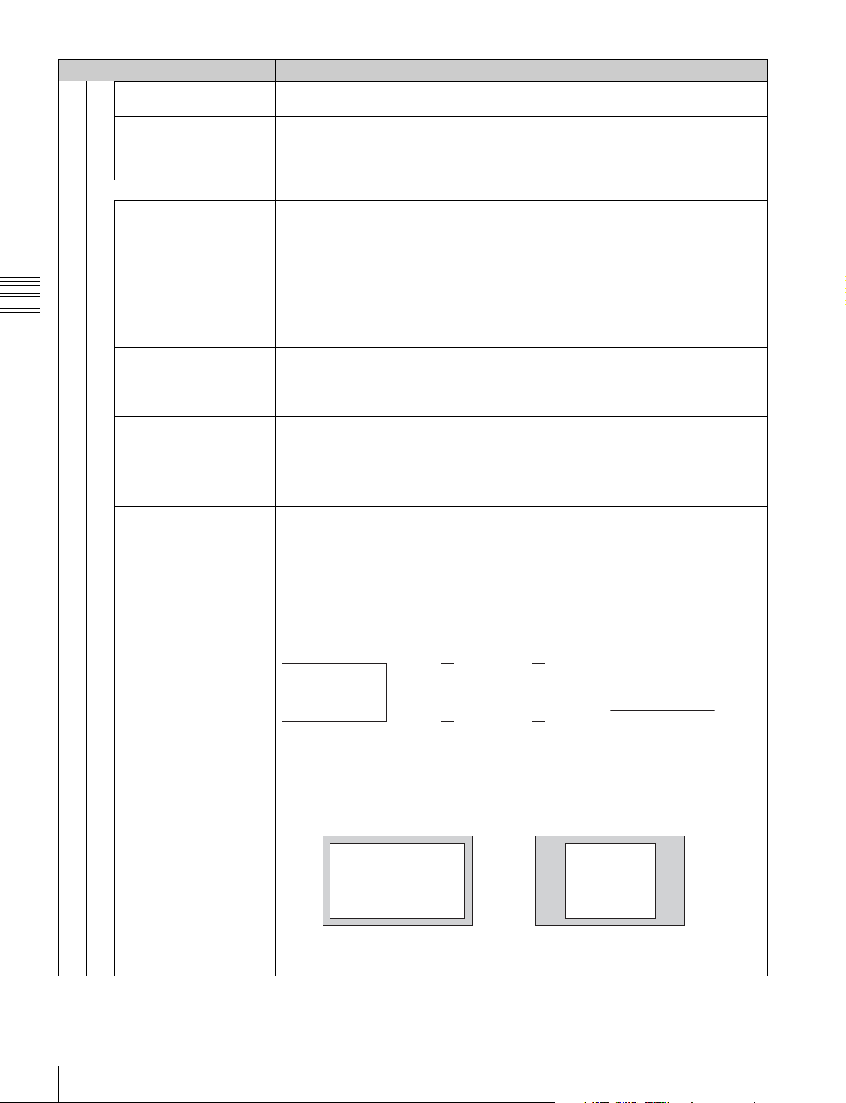
Menu Function and operation ([ ]: factory setting)
Bright Sets the luminance of the aspect marker.
You can select from High (bright) or [Low] (dark).
Blanking Sets the blanking outside the area of the aspect marker.
[Off]: Blanking is released.
Marker Setting
Area Marker 1 Sets the area marker 1.
Area Marker 1 Sets whether or not to display the area marker 1 when the MARKER button is pressed (Off or
Aspect Mode Sets the aspect ratio of the area marker 1.
Chapter 3 Menu
Aspect Sets the aspect ratio of the area marker 1 when Variable is selected in Aspect Mode.
Area Size Sets the size of the area marker 1.
Width Sets the width of the area marker 1 when Area Size is set to Variable (%) or Variable (dot).
Height Sets the height of the area marker 1 when Area Size is set to Variable (%) or Variable (dot).
Mode Sets the shape of the area marker 1.
Black: Blanking
Half: Half blanking
1)
.
[On])
1) Area Marker 2: ([Off], On)
You can select from [16:9], 15:9, 14:9, 13:9, 4:3, 2.39:1, 2.35:1, 1.85:1, 1.66:1, 1.896:1 or
Variable.
Note
When Variable (dot) is selected in Area Size, the size of the area marker 1 is set in pixel unit
of the input signal and the Aspect Mode setting becomes invalid.
Set to 1.00:1 to 3.00:1. [1.78]:1
You can select from [80%], 88%, 90%, 93%, Variable (%) or Variable (dot).
When Variable (%) is selected
Set to 050 to 100 (%). [080]
When Variable (dot) is selected
Set to 0360 to 2048 (dot). [0512]
When Variable (%) is selected
Set to 050 to 100 (%). [080]
When Variable (dot) is selected
Set to 0240 to 1080 (dot). [0384]
You can select from [Shape A], Shape B or Shape C.
Shape A
Shape B
Shape C
Function Setting Menu
70
Note
The size of the area is as follows depending on the Aspect Mode and 16:9 On/Off setting.
Example: Area Size 80%, Aspect Mode 16:9 or 4:3
With 16:9
80%
Aspect Mode 16:9
80%
Aspect Mode 4:3
Page 71
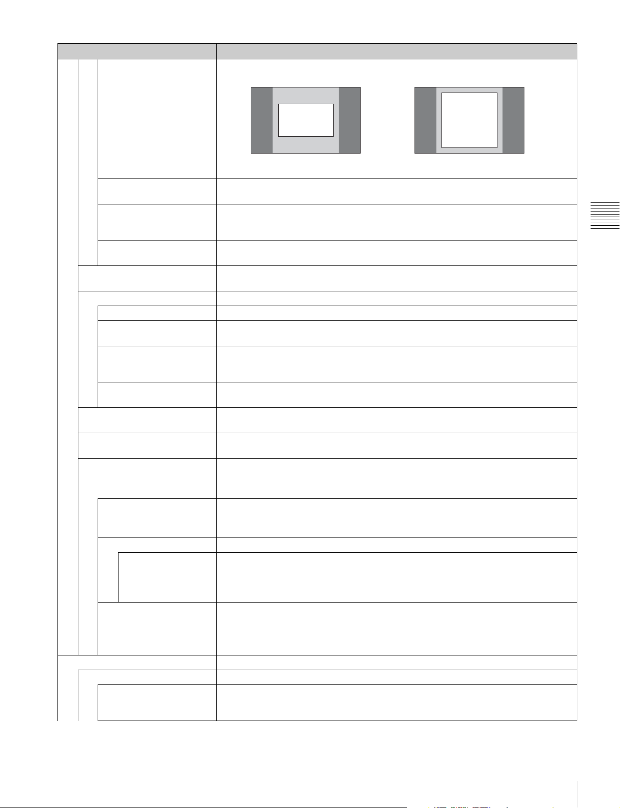
Menu Function and operation ([ ]: factory setting)
With 4:3
Marker Setting
Thickness Sets the thickness of the area marker 1.
Set to 1 to 5 (dots). [2]
Color Sets the color of the area marker 1.
You can select from [White] (white), Red (red), Green (green), Blue (blue), Yel low (yellow),
Cyan (cyan) or Magenta (magenta).
Bright Sets the luminance of the area marker 1.
You can select from High (bright) or [Low] (dark).
Area Marker 2 Sets the area marker 2.
The set items are the same as for Area Marker 1 (page 70).
Center Marker Sets the center marker.
Center Marker Sets whether or not to display the center marker ([Off] or On).
Mode Sets the display mode of the center marker.
You can select from [Short] (short) or Long (long).
Color Sets the color of the center marker.
You can select from [White] (white), Red (red), Green (green), Blue (blue), Yel low (yellow),
Cyan (cyan) or Magenta (magenta).
Bright Sets the luminance of the center marker.
You can select from High (bright) or [Low] (dark).
H Position Sets the horizontal position of the marker.
Set to –65 (leftward) to +65 (rightward). [00]
V Position Sets the vertical position of the marker.
Set to –35 (downward) to +35 (upward). [00]
Copy From Copies the other marker preset data.
Note
Use the controller with software version 1.6 or higher to use the Copy From function.
Preset Value Copies other data in this monitor.
When the item is selected, you can select from Marker1, Marker2, Marker3, Marker4 or
Marker5.
Other Monitor Copies data from another monitor.
Monitor ID Enter the ID number of the source monitor.
When the NETWORK switch is set to PEER TO PEER, this is not selectable.
When the ID number is entered, you can select from Marker1,
or Marker5.
Memory Stick Copies data in the “Memory Stick”.
When the item is selected, the file names in the source “Memory Stick” are displayed.
When the file is selected, you can select from Marker1, Marker2, Marker3, Marker4 or
Marker5.
P&P Setting Sets the multi display setting.
Side by Side Sets the side by side display.
Line Display Sets display mode of the boundary line.
[Off]: Not displayed.
On: Always displayed.
80%
Aspect Mode 16:9
80%
Aspect Mode 4:3
Chapter 3 Menu
Marker2, Marker3, Marker4
Function Setting Menu
71
Page 72
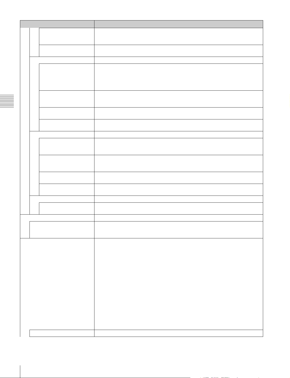
Menu Function and operation ([ ]: factory setting)
Line Color Sets the boundary line color of two pictures.
You can select from [White] (white), Red (red), Green (green), Blue (blue), Yellow (yellow),
Cyan (cyan), Magenta (magenta) or Black (black).
P&P Setting
Chapter 3 Menu
Pixel Zoom Setting Sets the pixel zoom.
Gamut Error Display Sets the gamut error display.
Line Bright Sets the luminance of the boundary line.
You can select from High (bright) or [Low] (dark).
Wipe Sets the wipe display.
Line Display Sets display mode of the boundary line.
[Auto]: Appears when the position of the boundary line is set and disappears after a
while.
On: Always displayed.
Off: Not displayed.
Line Color Sets the boundary line color.
You can select from [White] (white), Red (red), Green (green), Blue (blue), Yellow (yellow),
Cyan (cyan) or Magenta (magenta) or Black (black).
Line Bright Sets the luminance of the boundary line.
You can select from High (bright) or [Low] (dark).
Position Sets the position of the boundary line.
Set to –100 (leftward) to +100 (rightward). [000]
Butterfly Sets the butterfly display.
Line Display Sets display mode of the boundary line.
Off: Not displayed.
[On]: Always displayed.
Line Color Sets the boundary line color.
You can select from [White] (white), Red (red), Green (green), Blue (blue), Yellow (yellow),
Cyan (cyan) or Magenta (magenta) or Black (black).
Line Bright Sets the luminance of the boundary line.
You can select from High (bright) or [Low] (dark).
Position Sets the position of the boundary line.
Set to –100 to +100. [000]
Blending Sets the blending display.
Blending Ratio Sets the blending ratio when two images are mixed.
Set to 000 (Signal A disappears.) to 100% (Signal B disappears). [050]
Line Color Sets the boundary line color.
You can select from [White] (white), Red (red), Green (green), Blue (blue), Yellow (yellow),
Cyan (cyan) or Magenta (magenta) or Black (black).
A zebra pattern is superimposed on the portion where an error is detected.
Notes
• The gamut error display function is effective when the input signal is 3G/HD/SD SDI, HDMI,
or DisplayPort (and the quantization range for the signal is Limit). It is effective regardless
of the signal format, when Gamma is set to S-LOG Standard or S-LOG Full in the Color
Profile menu.
• The gamut error display function does not work in the following cases:
- When the input signal has no sync signal
- When the internal signal is displayed
- When H Delay/V Delay is set to On
- When Side by Side, Wipe, Butterfly or Blending is set to On
• In under scan mode, each one line of the upper and lower lines of the video signal is also
detected for gamut error display.
• The time code display, the closed caption display when the BKM-244CC is installed, and
the embedded audio level display when the BKM-250TG is installed are also detected for
gamut error display.
• In over scan mode, 5% mask portion is also detected for gamut error display. However, the
zebra pattern is not displayed on 5% mask portion.
Gamut Error Display Sets whether or not to display the gamut error ([Off] or On).
Function Setting Menu
72
Page 73
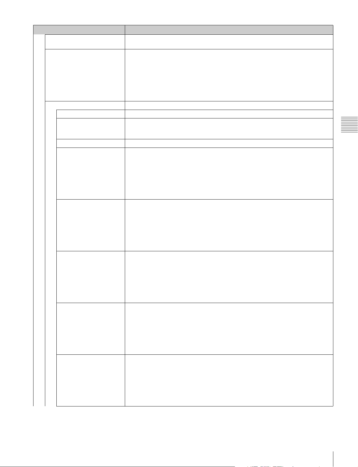
Menu Function and operation ([ ]: factory setting)
OSD Notification Sets whether or not to display the message of an error notification on the screen when the
error is detected ([Off] or On).
OSD Notification Reset Sets the method to reset the error detection mode.
[Auto]: Resets automatically after detecting the error.
Manual: Resets manually.
To reset the error detection, select Error Notify Clear (page 79) in the Function Switch
Gamut Error Display
Input Detection Sets the error detection of the input signal.
Detection Sets whether or not to detect the error of the input signal (Off or [On]).
Pixel Threshold Sets the pixel number of the gamut error in the frame to notify the gamut error detection.
Signal Level Sets the upper and lower lines of every signal to detect the gamut error.
SDI YCbCr 10bit Upper Limit (upper limit)
SDI RGB 10bit Upper Limit (upper limit)
SDI YCbCr 12bit Upper Limit (upper limit)
SDI RGB 12bit Upper Limit (upper limit)
HDMI/DP YCbCr Upper Limit (upper limit)
menu of the Function Setting menu or set Error Notify Clear to on by pressing the Error
Notify Clear button1) of the controller.
1) Error Notify Clear is assigned to a function button of the controller in the Function Key menu (page
92) of the Controller menu.
When the pixel number of the error is over the set pixel number, the detection is notified.
Set to 00000 to 65535. [00000]
Y: 0000 to 1023 [0983]
Cb: 0000 to 1023 [1004]
Cr: 0000 to 1023 [1004]
Lower Limit (lower limit)
Y: 0000 to 1023 [0020]
Cb: 0000 to 1023 [0019]
Cr: 0000 to 1023 [0019]
G: 0000 to 1023 [0983]
B: 0000 to 1023 [0983]
R: 0000 to 1023 [0983]
Lower Limit (lower limit)
G: 0000 to 1023 [0020]
B: 0000 to 1023 [0020]
R: 0000 to 1023 [0020]
Y: 0000 to 4095 [3935]
Cb: 0000 to 4095 [4019]
Cr: 0000 to 4095 [4019]
Lower Limit (lower limit)
Y: 0000 to 4095 [0080]
Cb: 0000 to 4095 [0077]
Cr: 0000 to 4095 [0077]
G: 0000 to 4095 [3935]
B: 0000 to
R: 0000 to 4095 [3935]
Lower Limit (lower limit)
G: 0000 to 4095 [0080]
B: 0000 to 4095 [0080]
R: 0000 to 4095 [0080]
Y: 0000 to 4095 [3935] (12bit conversion value)
Cb: 0000 to 4095 [4019] (12bit conversion value)
Cr: 0000 to 4095 [4019] (12bit conversion value)
Lower Limit (lower limit)
Y: 0000 to 4095 [0080] (12bit conversion value)
Cb: 0000 to 4095 [0077] (12bit conversion value)
Cr: 0000 to 4095 [0077] (12bit conversion value)
4095 [3935]
Chapter 3 Menu
Function Setting Menu
73
Page 74
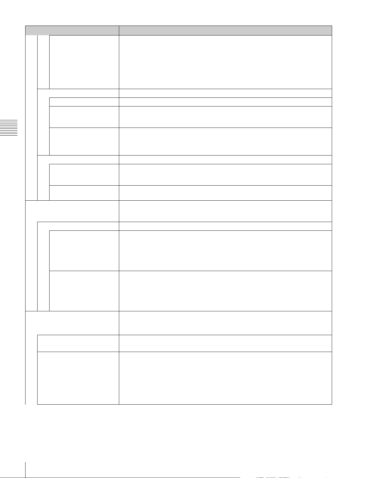
Menu Function and operation ([ ]: factory setting)
HDMI/DP RGB Upper Limit (upper limit)
G: 0000 to 4095 [3935] (12bit conversion value)
B: 0000 to 4095 [3935] (12bit conversion value)
R: 0000 to 4095 [3935] (12bit conversion value)
Lower Limit (lower limit)
G: 0000 to 4095 [0080] (12bit conversion value)
B: 0000 to 4095 [0080] (12bit conversion value)
Gamut Error Display
Post-Process Detection Sets the error detection setting for the signal after YCbCr is converted to RGB.
Detection Sets whether or not to detect the error of the input signal ([Off] or On).
Pixel Threshold Sets the pixel number of the gamut error in the frame to notify the gamut error detection.
Chapter 3 Menu
3D Setting Sets the mode of Horopter Check of the 3D signal analyzing function.
Capture Captures the still picture for the standard of the color evaluation (HD Frame Capture).
Signal Level Sets the upper and lower lines of the signal level.
Zebra Pattern Sets the zebra pattern displayed by the gamut error detection.
Line Sets the direction of the pattern.
Modulation Sets the amplitude of the pattern display.
Horopter Check Changes the display mode of the left and right 3D video signals.
Left Selects the display mode of the left signal.
Right Selects the display mode of the right signal.
Load Loads the captured picture from the “Memory Stick”.
Rename Changes a file name of the captured picture in the “Memory Stick”.
R: 0000 to 4095 [0080] (12bit conversion value)
When the pixel number of the error is over the set pixel number, the detection is notified.
Set to 00000 to 65535. [00000]
The signal level to be set is black level 256 and white level 3760 in 12bit conversion value.
Upper Limit: 0000 to 4095 [3761]
Lower Limit: 0000 to 4095 [0255]
[Diagonal Type1]: Right descending
Diagonal Type2: Left descending
Set to 1 to 50. [16]
This item can be selected when the BKM-250TG is installed, and is available for dual-stream
HD-SDI signal input.
[Normal]: Normal picture
Black: Displays a black signal (the video signal is not displayed).
Mono: Displays the video signal in monochrome mode.
Red: Displays only the red component of the video signal.
Blue: Displays only the blue component of the video signal.
[Normal]: Normal picture
Black: Displays a black signal (the video signal is not displayed).
Mono: Displays the video signal in monochrome mode.
Red: Displays only the red component of the video signal.
Blue: Displays only the blue component of the video signal.
Note
Use the controller with software version 1.6 or higher to use the HD Frame Capture function.
When the item is selected, you can select the file name to be loaded.
When the item is selected, the file names are displayed.
When the file name is selected, you can change the file name (1 to 20 characters).
Existing file name: Enter the existing file name.
New Name: Enter a new file name.
Note
The “.” must not be used as the first character.
Function Setting Menu
74
Page 75
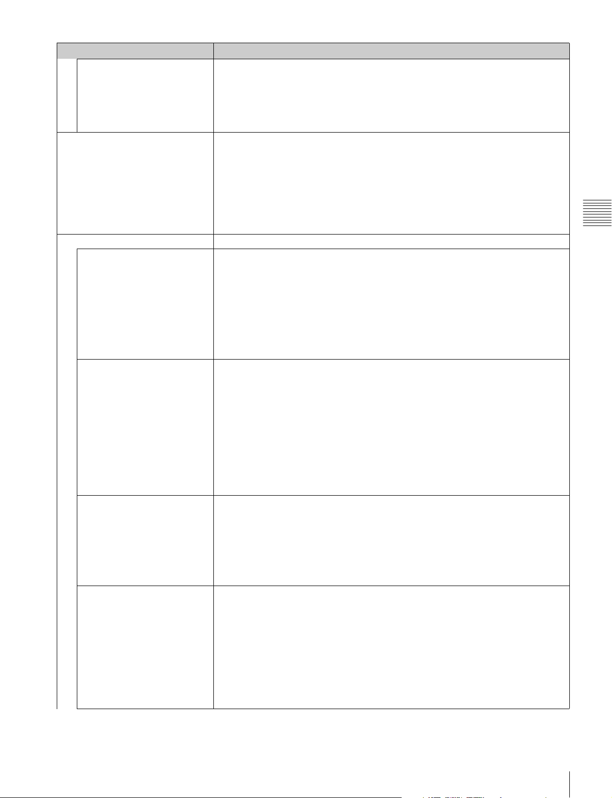
Menu Function and operation ([ ]: factory setting)
Delete Deletes the file of the captured picture in the “Memory Stick”.
When the item is selected, the file names in the “Memory Stick” are displayed.
Capture
Internal Signal Selects the internal signal display.
Function Switch Sets the function to be assigned to the function button of the controller in the menu.
Scan Mode Sets the scan mode of the picture.
Native Scan Sets whether or not to display the native scan ([Off] or On).
16:9 Sets whether or not to display the aspect in 16:9 or 1.896:1 (digital cinema signal) (Off or
H Delay Sets whether or not to display in H delay ([Off] or On).
When the file name is selected, the following message appears.
Delete this file?
OK: To delete the data, press the ENTER (Ent) button.
Cancel: To cancel, press the MENU button.
You can select from PLUGE, Gray (20% gray signal), White (100% white signal), 5 step (5
step gray scale signal), Ramp, Color Bars or Black (0% black signal).
To cancel the internal signal, select one from the channel numbers 1 to 30 with the numeric
buttons of the controller.
Note
Internal Signal is not set in the following cases:
• When the XYZ signal, or the HDMI/DisplayPort computer signal is input
• When Side by Side, Wipe, Butterfly or Blending is set to On
[Normal Scan]: Normal scan
Under Scan: 3% under scan
Over Scan: Mask of 5% over scan portion in the normal scan
Note
The scan mode is not selectable in the following cases:
• When Native Scan is set to On
• When the input signal has no sync signal
• When the internal signal is displayed
• When Side by Side, Wipe, Butterfly or Blending is set to On
Note
The native scan is not selectable in the following cases:
• When the input signal has no sync signal
• When Side by Side is set to On
• When Pixel Zoom is set to on
• When the HDMI/DisplayPort computer signal is input (The native scan is displayed
regardless of the setting.)
• When a digital cinema signal (2048 × 1080) is input and the internal signal is displayed
(Native Scan is set to Off and the normal scan is displayed regardless of the setting.)
• When the signal system is the SD signal of 720 × 576 or 1440 × 576, Native Scan Mode is
set to Aspect Correction × 2 and the internal signal is displayed (Native Scan is set to Off
and the normal scan is displayed regardless of the setting.)
[On]).
Notes
• The aspect ratio is not selectable in the following cases:
– When Native Scan Mode is set to ×1 or ×2 and Native Scan is set to On
– When the input signal has no sync signal
• The aspect ratio may be fixed to 16:9 due to the signal format.
For details, see “Available Signal Formats” on page 124.
When the 720/24, 25, 30P signal is input, the display position is changed with the PHASE
knob.
Notes
• The picture is not displayed in H delay in the following cases:
– When the input signal has no sync signal
– When the internal signal is displayed
– When Format of the Channel Configuration menu is set to HDMI or DisplayPort
– When Side by Side, Wipe, Butterfly or Blending is set to On
– When the captured frame is displayed
• The 3D signal analyzing function may not be performed correctly when H Delay is On.
Chapter 3 Menu
Function Setting Menu
75
Page 76
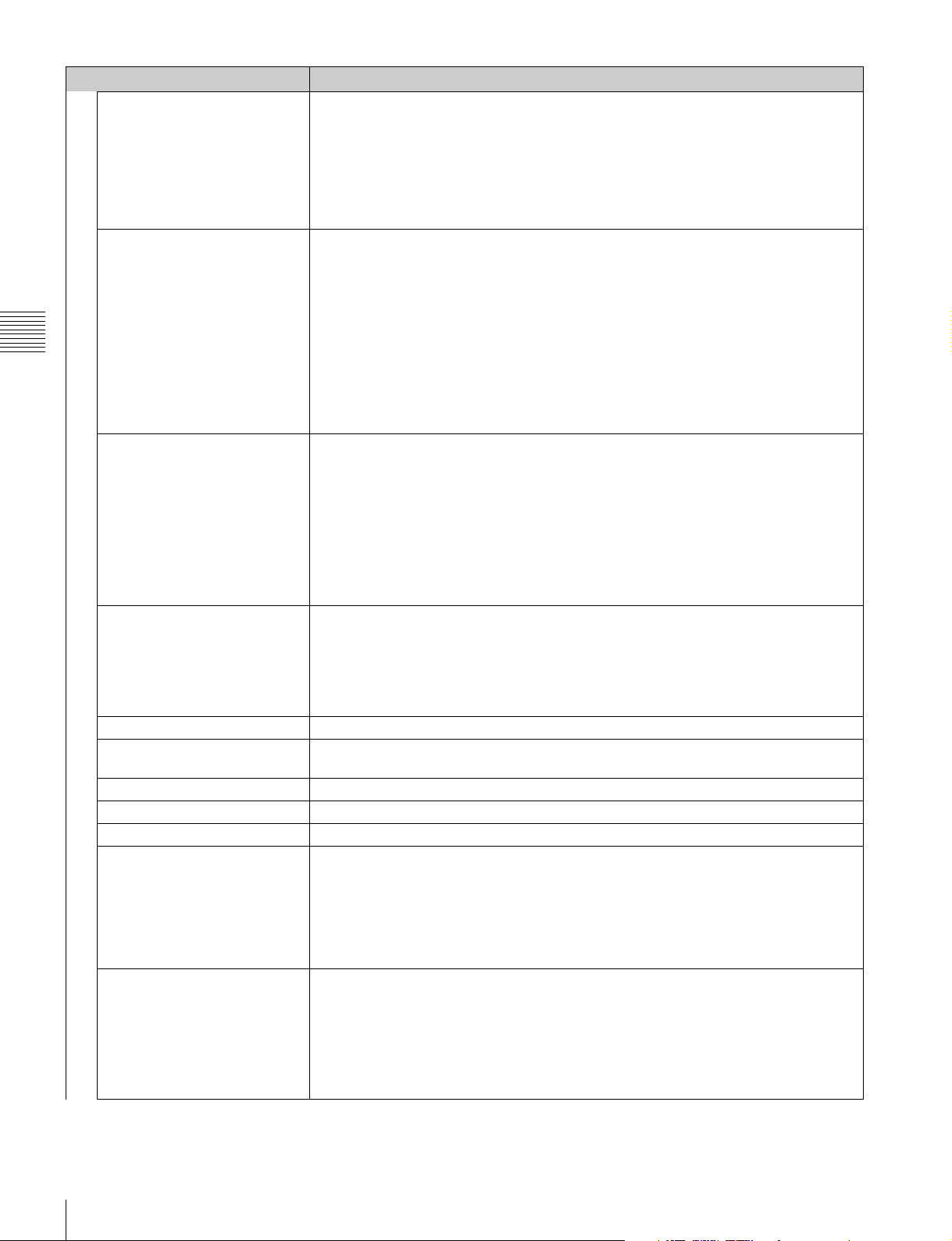
Menu Function and operation ([ ]: factory setting)
V Delay Sets whether or not to display in V delay ([Off] or On).
Note
The picture is not displayed in V delay in the following cases:
• When the input signal has no sync signal
• When the internal signal is displayed
Function Switch
External Sync Sets whether or not to select external sync mode ([Off] or On) when the analog component
Chapter 3 Menu
Comb Sets whether or not to use the comb filter (Off or [On]).
Aperture Sets whether or not to function the aperture modification (Off or On).
Mono Sets whether or not to display in monochrome mode ([Off] or On).
Blue Only Sets whether or not to display only the blue signal as a monochrome picture after cutting the
R Off Sets whether or not to cut the red signal ([Off] or On).
G Off Sets whether or not to cut the green signal ([Off] or On).
B Off Sets whether or not to cut the blue signal ([Off] or On).
Chroma Up Sets whether or not to increase the chroma value by 12 dB ([Off] or On).
Interlace Sets whether or not to display in interlace mode ([Off] or On).
• When Format of the Channel Configuration menu is set to HDMI or DisplayPort
• When Side by Side, Wipe, Butterfly or Blending is set to On
• When the captured frame is displayed
signal or analog RGB signal format is input.
When On is selected, the signal to be displayed is synchronized with the sync signal input to
the SYNC connector (External Sync).
When Off is selected, the signal to be displayed is synchronized with the sync signal included
in the signals being monitored (Internal Sync).
Notes
• When Component is set to YPbPr or RGB in Format of the Channel Configuration menu,
you can set the external sync.
• The external sync is not set in the following cases:
– When the internal signal is displayed
– When the captured frame is displayed
When Off is selected, the trap · band-pass filter (Trap/BPF) is selected.
You can select the type of comb filter in NTSC Comb Filter menu (page 68) of the Auxiliary
Setting menu.
Notes
• When Composite is set to Auto, NTSC, PAL or PAL-M in Format of the Channel
Configuration menu, you can set the comb filter.
• The comb filter is not set in the following cases:
– When the internal signal is displayed
– When the captured frame is displayed
[Off] (when the signal is displayed in Aspect Correction mode of the native display), [On]
(when the signal is displayed in mode other than Aspect Correction of the native display)
Note
When the HDMI/DisplayPort computer signal is input, the aperture modification does not
function.
red and green signals ([Off] or On).
Note
The chroma value is not increased in the following cases:
• When the signal to be displayed is RGB or XYZ
• When the composite signal is automatically displayed in monochrome depending on the
color discrimination of the input adaptor
• When the internal signal is displayed
Notes
• Set Native Scan to On for the interlace display.
• The picture is not displayed in interlace mode in the following cases:
– When Side by Side, Wipe, Butterfly or Blending is set to On
– When Pixel Zoom is set to on
For details of this menu, see “Selecting Display Mode” on page 97.
Function Setting Menu
76
Page 77
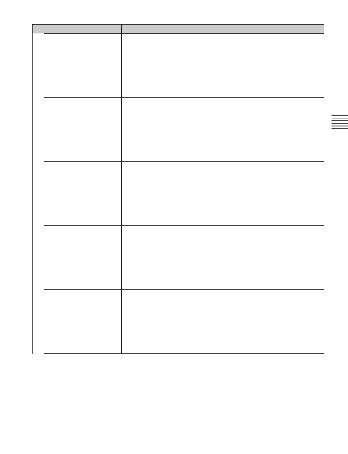
Menu Function and operation ([ ]: factory setting)
Marker Sets whether or not to display all markers ([Off] or On).
Notes
• The marker is not displayed in the following cases:
– When the input signal has no sync signal
– When the internal signal is displayed
Function Switch
Aspect Marker Sets whether or not to display the aspect marker ([Off] or On).
Area Marker 1 Sets whether or not to display the area marker 1 ([Off] or On).
Area Marker 2 Sets whether or not to display the area marker 2 ([Off] or On).
Center Marker Sets whether or not to display the center marker ([Off] or On).
– When the HDMI/DisplayPort computer signal is input
– When H Delay/V Delay is set to On
– When Side by Side, Wipe, Butterfly or Blending is set to On
– When Pixel Zoom is set to on
• The marker may be displayed in an incorrect position when External Sync is On.
Notes
• The aspect marker is not displayed in the following cases:
– When the input signal has no sync signal
– When the internal signal is displayed
– When the HDMI/DisplayPort computer signal is input
– When H Delay/V Delay is set to On
– When Side by Side, Wipe, Butterfly or Blending is set to On
– When Pixel Zoom is set to on
• The aspect marker may be displayed in an incorrect position when External Sync is On.
Notes
• The area marker 1 is not displayed in the following cases:
– When the input signal has no sync signal
– When the internal signal is displayed
– When the HDMI/DisplayPort computer signal is input
– When H Delay/V Delay is set to On
– When Side by Side, Wipe, Butterfly or Blending is set to On
– When Pixel Zoom is set to on
• The area marker 1 may be displayed in an incorrect position when External Sync is On.
Notes
• The area marker 2 is not displayed in the following cases:
– When the input signal has no sync signal
– When the internal signal is displayed
– When the HDMI/DisplayPort computer signal is input
– When H Delay/V Delay is set to On
– When Side by Side, Wipe, Butterfly or Blending is set to On
– When Pixel Zoom is set to on
• The area marker 2 may be displayed in an incorrect position when External Sync is On.
Notes
• The center marker is not displayed in the following cases:
– When the input signal has no sync signal
– When the internal signal is displayed
– When the HDMI/DisplayPort computer signal is input
– When H Delay/V Delay is set to On
– When Side by Side, Wipe, Butterfly or Blending is set to On
– When Pixel Zoom is set to on
• The center marker may be displayed in an incorrect position when External Sync is On.
Chapter 3 Menu
Function Setting Menu
77
Page 78
Menu Function and operation ([ ]: factory setting)
Aspect Marker-Line Sets whether or not to display the line of the aspect marker ([Off] or On).
Notes
• The line of the aspect marker is not displayed in the following cases:
– When the input signal has no sync signal
– When the internal signal is displayed
Function Switch
Aspect Blanking-Half Sets whether or not to set the Aspect Blanking (the blanking outside the area of the aspect
Chapter 3 Menu
Aspect Blanking-Black Sets whether or not to set the blanking level of the Aspect Blanking (the blanking outside the
Side by Side Sets whether or not to display in the side by side display ([Off] or On).
Wipe Sets whether or not to display in the wipe display ([Off] or On).
Butterfly Sets whether or not to display in the butterfly display ([Off] or On).
Blending Sets whether or not to display in the blending display ([Off] or On).
– When the HDMI/DisplayPort computer signal is input
– When H Delay/V Delay is set to On
– When Side by Side, Wipe, Butterfly or Blending is set to On
– When Pixel Zoom is set to on
• The line of the aspect marker may be displayed in an incorrect position when External Sync
is On.
marker) to half blanking ([Off] or On).
Notes
• The Aspect Blanking is not set to half blanking in the following cases:
– When the input signal has no sync signal
– When the internal signal is displayed
– When the HDMI/DisplayPort computer signal is input
– When H Delay/V Delay is set to On
– When Side by Side, Wipe, Butterfly or Blending is set to On
– When Pixel Zoom is set to on
• The Aspect Blanking may be displayed in an incorrect position when External Sync is On.
area of the aspect marker) to 0% black level ([Off] or On).
Notes
• The Aspect Blanking is not set to 0% black level in the following cases:
– When the input signal has no sync signal
– When the internal signal is displayed
– When the HDMI/DisplayPort computer signal is input
– When H Delay/V Delay is set to On
– When Side by Side, Wipe, Butterfly or Blending is set to On
– When Pixel Zoom is set to on
• The Aspect Blanking may be displayed in an incorrect position when External Sync is On.
Note
The side by side display is not set in the following cases:
• When the internal signal is displayed
• When Pixel Zoom is set to on
Note
The wipe display is not set in the following cases:
• When the internal signal is displayed
• When Pixel Zoom is set to on
Note
The butterfly display is not set in the following cases:
• When the internal signal is displayed
• When Pixel Zoom is set to on
Note
The blending display is not set in the following cases:
• When the internal signal is displayed
• When Pixel Zoom is set to on
Function Setting Menu
78
Page 79
Menu Function and operation ([ ]: factory setting)
Error Notify Clear When the item is selected, the notification of the gamut error detection (OSD Notification) is
cleared.
Note
The Error Notify Clear is not selected in the following cases:
• When Gamut Error Display is set to Off in the Gamut Error Display menu of the Function
Function Switch
Audio Level Meter Sets whether or not to display the audio level meter ([Off] or On).
ALM Hold Reset When the item is selected, the peak hold of the audio level meter is canceled.
Time Code Sets whether or not to display the time code ([Off] or On).
Difference Sets whether or not to display the difference between the luminance of the left 3D video
Checkerboard Sets whether or not to display the left and right 3D video signals in a checkerboard pattern
Setting menu.
• When OSD Notification Reset is set to Auto in the Gamut Error Display menu of the
Function Setting menu.
Note
When the option port number in which the BKM-250TG is installed is not selected in Input
Port of the Channel Configuration menu, the audio level meter cannot be displayed.
Note
The ALM Hold Reset is not selected in the following cases:
• When the option slot number in which the BKM-250TG is installed is not selected in Input
Port of the Channel Configuration menu
• When Audio Level Meter is set to Off
• When Peak Hold is set to Off or Auto in the Audio Level Meter menu of the On Screen Set
menu of the System Configuration menu
signal and that of the right signal ([Off] or On).
This item is available for dual-stream HD-SDI signals.
Notes
• The Difference display cannot be set in the following cases:
– When the option port number in which the BKM-250TG is installed is not selected in
Input Port of the Channel Configuration menu
– When dual-link display is used
– When the internal signal is displayed
– When a captured frame is displayed
– When Side by Side, Wipe, Butterfly or Blending is set to On
• The Difference display may not be performed correctly when H Delay is set to On.
• If saving is performed in HD Frame Capture, this function is deactivated and the normal
display is restored.
([Off] or On).
This item is available for dual-stream HD-SDI signals.
Notes
• The Checkerboard display cannot be set in the following cases:
– When the option port number in which the BKM-250TG is installed is not selected in
Input Port of the Channel Configuration menu
– When dual-link display is used
– When the internal signal is displayed
– When a captured frame is displayed
– When Side by Side, Wipe, Butterfly or Blending is set to On
• The Checkerboard display may not be performed correctly when H Delay is set to On.
• If saving is performed in HD Frame Capture, this function is deactivated and the normal
display is restored.
Chapter 3 Menu
Function Setting Menu
79
Page 80
Menu Function and operation ([ ]: factory setting)
L/R Switch Sets whether or not to display either the left and right 3D video signals on the screen by
switching them alternately ([Off] or On).
This item is available for dual-stream HD-SDI signals.
Notes
• The L/R Switch display cannot be set in the following cases:
– When the option port number in which the BKM-250TG is installed is not selected in
Input Port of the Channel Configuration menu
– When dual-link display is used
– When the internal signal is displayed
– When a captured frame is displayed
– When Side by Side, Wipe, Butterfly or Blending is set to On
• The L/R Switch display may not be performed correctly when H Delay is set to On.
• If saving is performed in HD Frame Capture, this function is deactivated and the normal
display is restored.
On).
This item is available for dual-stream HD-SDI signals.
Notes
• The Horopter Check display cannot be set in the following cases:
– When the option port number in which the BKM-250TG is installed is not selected in
Input Port of the Channel Configuration menu
– When dual-link display is used
– When the internal signal is displayed
– When a captured frame is displayed
– When Side by Side, Wipe, Butterfly or Blending is set to On
• The Horopter Check display may not be performed correctly when H Delay is set to On.
• If saving is performed in HD Frame Capture, this function is deactivated and the normal
display is restored.
This item is available for dual-stream HD-SDI signals.
Notes
• The Flip H display cannot be set in the following cases:
– When the option port number in which the BKM-250TG is installed is not selected in
Input Port of the Channel Configuration menu
– When dual-link display is used
– When the internal signal is displayed
– When a captured frame is displayed
– When Side by Side, Wipe, Butterfly or Blending is set to On
• The Flip H display may not be performed correctly when H Delay is set to On.
Chapter 3 Menu
Function Switch
Horopter Check Sets whether or not to display the left and right 3D video signals in various modes ([Off] or
Flip H Sets whether or not to invert the 3D video signals horizontally to be displayed ([Off] or On).
Function Setting Menu
80
Page 81
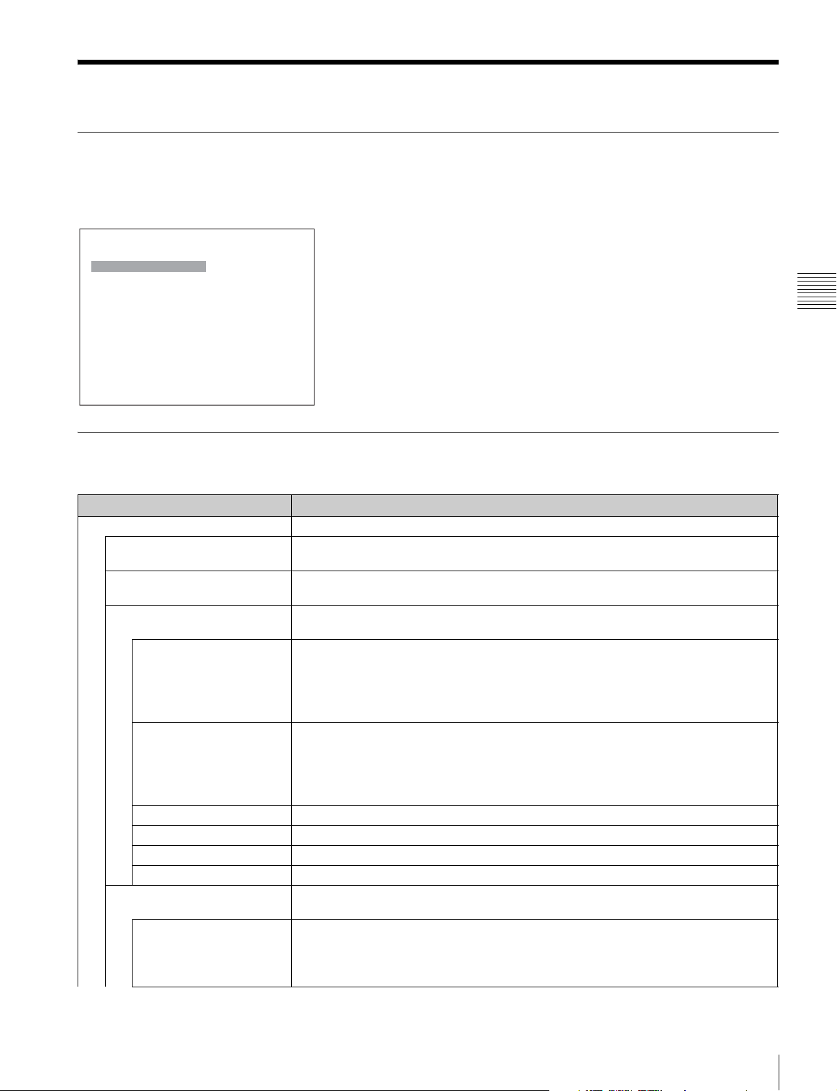
System Configuration Menu
Overview
This menu is used to set the system such as the network, parallel remote control function, etc.
When System Configuration is selected, the following menu is displayed.
iSystem Configuration
Network B
Parallel Remote B
Power B
On Screen Set B
Password B
Date/Time B
Scan Mode Skip: xxx
Screen Saver: xxx
Monitor Upgrade B
Maintenance B
Menu Function and Operation
Chapter 3 Menu
Menu Function and operation ([ ]: factory setting)
Network Sets the remote control function of the network.
Monitor ID Enter a monitor ID number.
Set to 01 to 99. [01]
Group ID Enter a group ID number.
Set to 01 to 99. [01]
Network Setting Sets the IP address, subnet mask and default gateway.
For the setting value, consult the network administrator.
IP Address Sets the IP address. [192.168.000.001]
Note
When the NETWORK switch is set to PEER TO PEER, the IP address is set to “192.168.0.1”
regardless of the display.
When the NETWORK switch is set to LAN, the IP address is set to the displayed one.
Subnet Mask Sets the subnet mask. [255.255.255.000]
Note
When the NETWORK switch is set to PEER TO PEER, the subnet mask is set to
“255.255.255.000” regardless of the display.
When the NETWORK switch is set to LAN, the subnet mask is set to the displayed one.
Default Gateway Sets whether or not to set the default gateway ([Off] or On).
Address Sets the address of the default gateway. [---.---.---.--- (no setting)]
Cancel Cancels the changed or confirmed setting.
Confirm Saves the changed or confirmed setting.
Protocol Setting Sets the required items for communications such as the port number.
For the setting value, consult the network administrator.
SDCP/SDAP Community Sets the SDCP/SDAP community name.
When the item is selected, you can enter the community name (four characters).
SONY: SONY is entered as a community name.
New Name: Enter a new name.
System Configuration Menu
81
Page 82
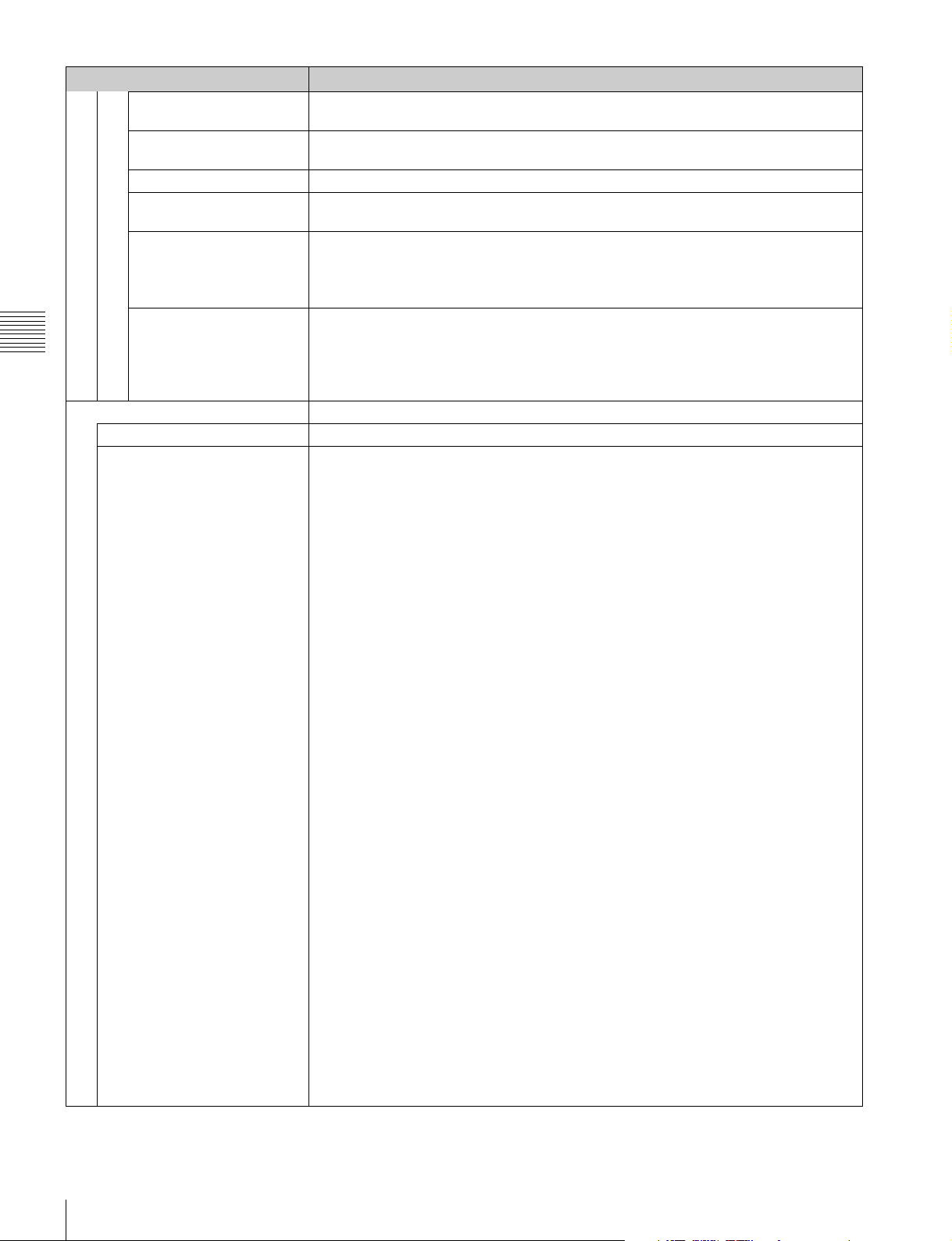
Menu Function and operation ([ ]: factory setting)
SDCP Port No Sets the SDCP port number.
Set to 53434 to 53534. [53484]
Network
Chapter 3 Menu
Parallel Remote Sets the parallel remote function.
SDAP Port No Sets the SDAP port number.
Set to 53812 to 53912. [53862]
SDAP Broadcast Sets whether or not to issue the SDAP (Disable or [Enable]).
SDAP Broadcast Period Sets the period (seconds) to issue the SDAP.
Set to 05 to 30. [15]
Acceptable IP Address Sets the IP address to connect.
When the item is selected, you can set IP1 to IP4.
Cancel: Cancels the changed or confirmed setting.
Confirm: Saves the changed or confirmed setting.
Reset Protocol Setting Resets the protocol setting.
When the item is selected, the following message appears.
Are you sure?
OK: To reset data, press the ENTER (Ent) button.
Cancel: To cancel, press the MENU button.
Parallel Remote Selects whether or not to use the parallel remote functions. ([Off] or On)
1 Pin to 8 Pin Assigns the function to each pin of the PARALLEL REMOTE connector when Parallel Remote
is set to On.
The default assignment of functions is as follows:
1 Pin: [CH01]
2 Pin: [CH02]
3 Pin: [External Sync]
4 Pin: [Mono]
5 Pin: [Marker]
6 Pin: [unused]
7 Pin: [unused]
8 Pin: [Tally]
You can change the assignment to the following functions for pins 1 to 8.
The functions shown with item name only are the same as those assigned to the function
buttons on the controller.
For details on these functions, see “Function Key” (page 92) of the Controller menu.
Parallel Remote (1/5)
CH01 to 30: Selects a channel number. Enter the desired channel number with the
numeric buttons.
----: Unused
Under Scan,
Comb
1) The scan mode is set to Normal Scan when Under Scan or Over Scan is off.
Parallel Remote (2/5)
Aperture, Mono, Blue Only, R Off, G Off, B Off, Chroma Up, Interlace
Tal ly: The function to turn on the tally lamp
Power Off: The monitor power function
Parallel Remote (3/5)
Marker, Aspect Marker, Area Marker 1, Area Marker 2, Center Marker, Aspect
Marker-Line, Aspect Blanking-Half, Aspect Blanking-Black
Parallel Remote (4/5)
Side by Side, Wipe, Butterfly, Blending, Error Notify Clear, Audio Level Meter, ALM
Hold Reset, Time Code
Parallel Remote (5/5)
Difference, Checkerboard, L/R Switch, Horopter Check, Flip H
For the pin assignment, see “PARALLEL REMOTE connector” in Location and Function of
Parts on page 17 (BVM-E250A) or page 20 (BVM-E170A).
1)
Over Scan,1) Native Scan, 16:9, H Delay, V Delay, External Sync,
System Configuration Menu
82
Page 83
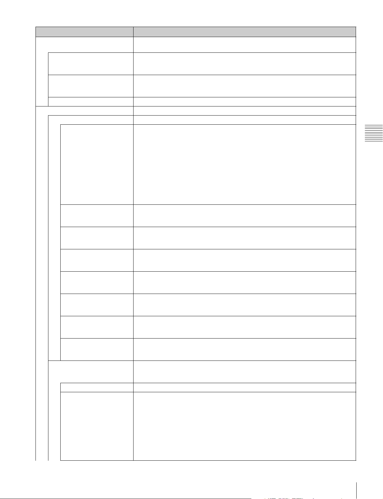
Menu Function and operation ([ ]: factory setting)
Power Sets the status of the monitor when the main power is turned on or the power is turned on by
remote operation.
Standby Mode Sets the status when the MAIN POWER switch is turned on.
[Off]: Operation mode
On: Standby mode
Power On Status Sets the input channel when the power is turned on.
[Last]: Sets to the channel that was selected at the time the power was last turned off.
CH: Sets to the channel number specified in Default CH.
Default CH Selects the channel (01 to 30) when the Power On Status is set to CH. [01]
On Screen Set Sets the items for the screen display.
Input Information Sets the display of the input information.
Format Sets the display mode of the signal system.
[Auto]: Disappears after being displayed for a while.
Off: Not displayed.
Note
The picture rate display is 23.98, 29.97 or 59.94 (example 1080/59.94P) when the signal is
input from the standard SDI input or the BKM-250TG, Format is set to 3G/HD/SD-SDI Auto
(page 58) in the Channel Configuration menu, and the Picture Rate information for the
Payload ID is 23.98, 29.97 or 59.94, even if the monitor determines the picture rate as 24 Hz,
30 Hz or 60 Hz.
For details on Payload ID, see “SDI Payload ID Status” (page 90) of the System Status menu
or “Displaying the Monitor Status Page” (page 108).
Position Sets the display position for the signal system.
You can select from Top Left (top left), Top C e n t e r (top center), Top Right (top right),
[Bottom Left] (bottom left), Bottom Center (bottom center) or Bottom Right (bottom right).
CH No Sets the display mode of the channel number.
[Auto]: Disappears after being displayed for a while.
Off: Not displayed.
Position Sets the display position for the channel number.
You can select from Top Left (top left), Top C e n t er (top center), [Top Right] (top right),
Bottom Left (bottom left), Bottom Center (bottom center) or Bottom Right (bottom right).
CH Name Sets the display mode of the channel name.
[Auto]: Disappears after being displayed for a while.
Off: Not displayed.
Position Sets the display position for the channel name.
You can select from [Top Left] (top left), Top Center (top center), Top Right (top right),
Bottom Left (bottom left), Bottom Center (bottom center) or Bottom Right (bottom right).
Scan Mode Sets the display mode of the scan mode.
[Auto]: Disappears after being displayed for a while.
Off: Not displayed.
Position Sets the display position for the scan mode.
You can select from Top Left (top left), Top C e n t er (top center), Top Right (top right),
Bottom Left
Closed Caption Sets the items for the closed caption display.
When the BKM-244CC is installed, you can select the item.
The setting is effective for the input signal of the BKM-244CC.
Closed Caption Sets whether or not to display closed caption signal ([Off] or On).
Type Sets the closed caption type.
[Auto1]: Select to set to 608(VBI) when the SD-SDI signal is input or 708 when the HDSDI signal is input.
Auto2: Select to set to 608(VBI) when the SD-SDI signal is input or 608(708) when the
HD-SDI signal is input.
708: Select to display the closed caption signal of the EIA/CEA-708 standards.
608 (708): Select to display the closed caption signal of the EIA/CEA-608 standards
transmitted by EIA/CEA-708 standards.
608 (VBI): Select to display the closed caption signal of the EIA/CEA-608 standards
transmitted by using the line 21.
(bottom left), Bottom Center (bottom center) or [Bottom Right] (bottom right).
Chapter 3 Menu
System Configuration Menu
83
Page 84
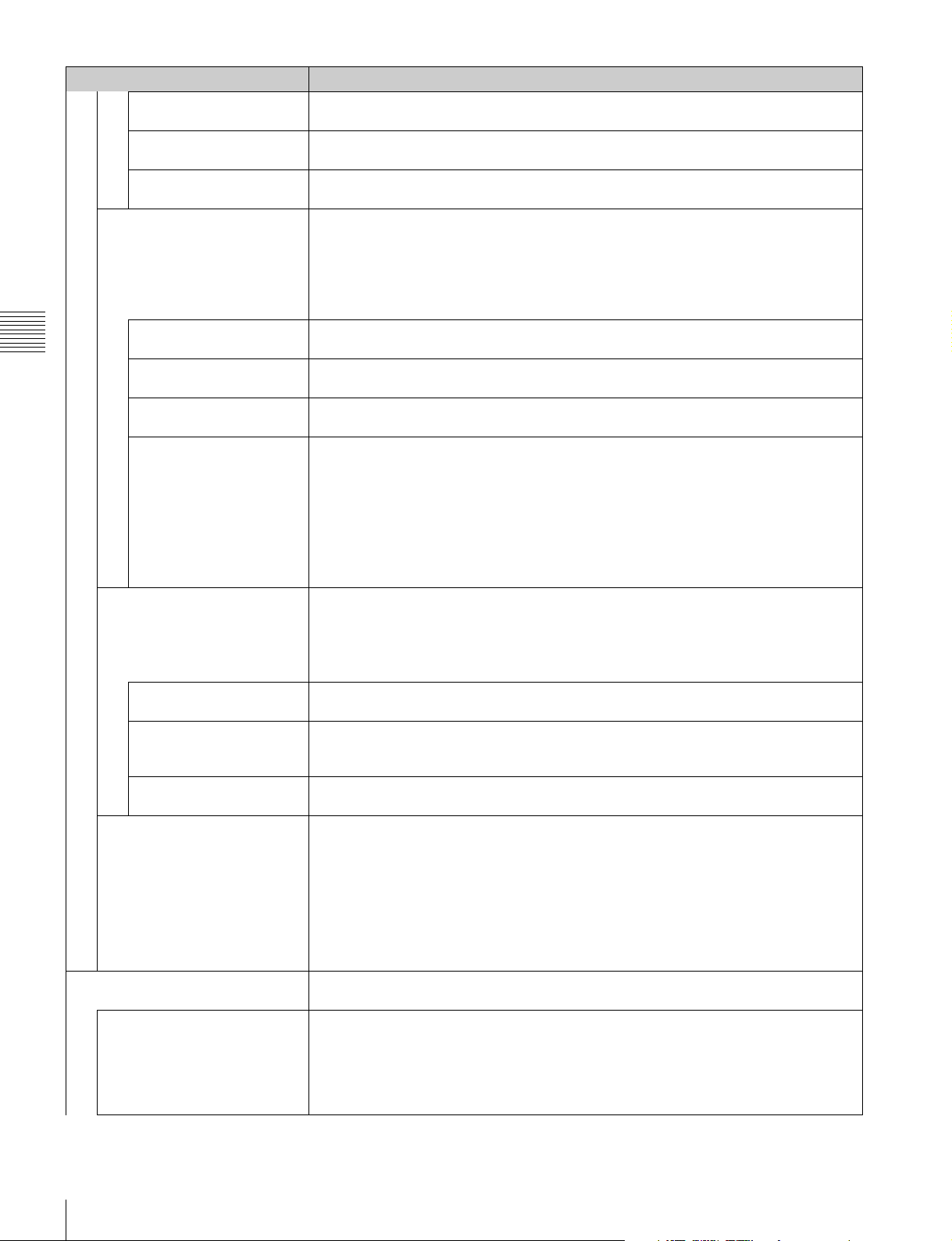
Menu Function and operation ([ ]: factory setting)
Service 708 Sets Service when Type is set to 708.
You can select from Service1 to Service6. [Service1]
Service 608 Sets Service when Type is set to 608 (VBI) or 608 (708).
You can select from CC1 to CC4 or Text 1 to Text4. [CC1]
On Screen Set
Chapter 3 Menu
Password Sets the password for the menu.
OSD Level Sets the luminance of the letter.
You can select from High (bright), or [Low] (dark).
Audio Level Meter Sets the audio level meter.
When the BKM-250TG is installed, you can select the item.
The setting is effective for the input signal of the BKM-250TG.
Note
As the audio level meter is superimposed on the video signal, the audio level meter may be
cut partially because of the scan mode setting of the monitor.
Audio CH Sets the audio channel.
You can select from [CH1-CH8] or CH9-CH16.
Position Sets the display position of the audio level meter.
You can select from [Bottom] (bottom) or To p (top).
Transparency Sets the transparency of the background of the audio level meter.
You can select from Black (black) or [Half] (translucence).
Peak Hold Sets the peak hold mode of the audio level meter.
[Off]: The peak hold does not function.
Auto: The peak hold is automatically released after about 1 second.
Manual Reset: The peak hold is released manually.
To release the peak hold, select ALM Hold Reset (page 79) in the Function Switch menu
of the Function Setting menu or set ALM Hold Reset to on by pressing the ALM Hold
Reset button
1)ALM Hold Reset is assigned to the controller in the Function Key menu (page 92) of the Controller
menu.
Time Code Sets the time code.
The setting is effective when the SDI signal is input.
Note
As the time code is superimposed on the video signal, the time code may be cut partially
because of the scan mode setting of the monitor.
VITC/LTC Sets the type of the time code.
You can select from [VITC] or LTC.
Position Sets the display position of the time code.
You can select from Top Left (top left), [Top Center] (top center), Top Right (top right),
Bottom Left (bottom left), Bottom Center (bottom center) or Bottom Right (bottom right).
Level Sets the luminance of the time code.
You can select High (bright) or [Low] (dark).
Over Range When a portion of the signal exceeds the dynamic range of the internal signal processing
circuit, it is determined as Over Range. This menu sets whether or not to display a zebra
pattern on the detected Over Range portion ([Off], On).
When Over Range is detected, adjust the contrast or brightness to a lower level.
Notes
• When Over Range occurs, the OVER RANGE lamp on the front of the unit lights in amber
regardless of the setting of this menu.
• When Gamut Error Display of the Function Setting menu is set to On, the zebra pattern in
the area where the error was detected is also included as a detection target of Over Range.
Enter a four-digit number for the password. [9999]
Change Password Changes the password.
Enter New Password: Enter a new password with the numeric buttons and press the
ENTER (Ent) button.
Re-Enter Password: Enter the new password again and press the ENTER (Ent) button.
The password is registered.
To change it, press the MENU button.
1)
of the controller.
System Configuration Menu
84
Page 85
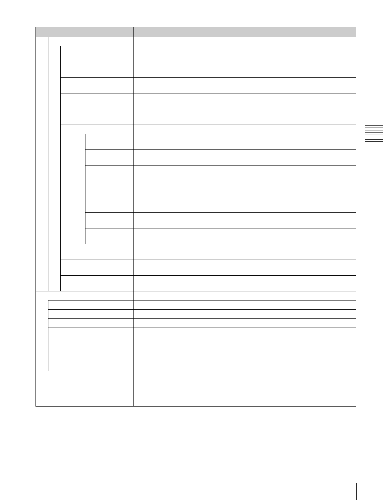
Menu Function and operation ([ ]: factory setting)
Apply Password Sets whether or not to apply the password to each menu (Yes or [No]).
Adjustment Yes: Apply the password.
Password
Date/Time When the item is selected, you can set or change the date and time.
Scan Mode Skip Sets the scan mode to be skipped when the SCAN button is pressed in the single mode
Channel Configuration Ye s: Apply the password.
Auxiliary Setting Yes : Apply the password.
Function Setting Yes : Apply the password.
System Configuration Yes: Apply the password.
Individual Item Sets whether or not to apply the password to the System Configuration menu.
Network Yes : Apply the password.
Parallel Remote Yes: Apply the password.
Power Yes: Apply the password.
On Screen Set Yes: Apply the password.
Date/Time Yes: Apply the password.
Scan Mode Skip Yes : Apply the password.
Screen Saver Yes: Apply the password.
File Management Yes: Apply the password.
Controller Ye s: Apply the password.
Key Protect Ye s: Apply the password.
Year Sets the year.
Month Sets the month.
Day Sets the day.
Hour Sets the hour (in 24-hour display).
Minute Sets the minute.
Cancel Cancels the setting.
Confirm Executes the setting.
[No]: Not apply the password.
[No]: Not apply the password.
[No]: Not apply the password.
[No]: Not apply the password.
[No]: Not apply the password.
[No]: Not apply the password.
[No]: Not apply the password.
[No]: Not apply the password.
[No]: Not apply the password.
[No]: Not apply the password.
[No]: Not apply the password.
[No]: Not apply the password.
[No]: Not apply the password.
[No]: Not apply the password.
[No]: Not apply the password.
Second is set to 0.
connection.
[None]: No scan is skipped.
Under Scan: The under scan is skipped.
Over Scan: The over scan is skipped.
Chapter 3 Menu
System Configuration Menu
85
Page 86
Menu Function and operation ([ ]: factory setting)
Screen Saver Sets the screen saver function.
[On]: When a still image is displayed on the screen for 10 minutes or more, the
brightness of the screen is automatically reduced to prevent burn-in of the screen. The
brightness returns to normal if you input a moving image or operate the controller.
Approximately one minute before the screen saver is activated, the ECO lamp starts
flashing rapidly. Then the flashing slows in green when the screen saver is activated.
Off: Disables the screen saver function.
Note
The screen saver function is automatically set to On during manual adjustment of the color
temperature, contrast, brightness, chroma, and phase, regardless of the setting of this item.
Monitor Upgrade Upgrades the monitor.
When the item is selected, the screen for inputting the password is displayed.
After the 4-digit password is entered, the current versions of Software Version, Kernel
Version, FPGA Version, and DisplayPort Version are displayed.
Chapter 3 Menu
Software Upgrade Upgrades the software for the monitor.
Kernel Upgrade Upgrades the kernel of the monitor.
FPGA Upgrade Upgrades the FPGA data of the monitor.
DisplayPort Upgrade Upgrades the DisplayPort data of the monitor.
Maintenance The menu for the Sony service representative is displayed.
For the FPGA Version, FPGA1 , FPGA2 and FPGA CORE are displayed from left to right.
For the password, see Password (page 84) of the System Configuration menu.
For details on upgrading the monitor, see “Upgrading the Monitor and Controller” on page
111.
System Configuration Menu
86
Page 87
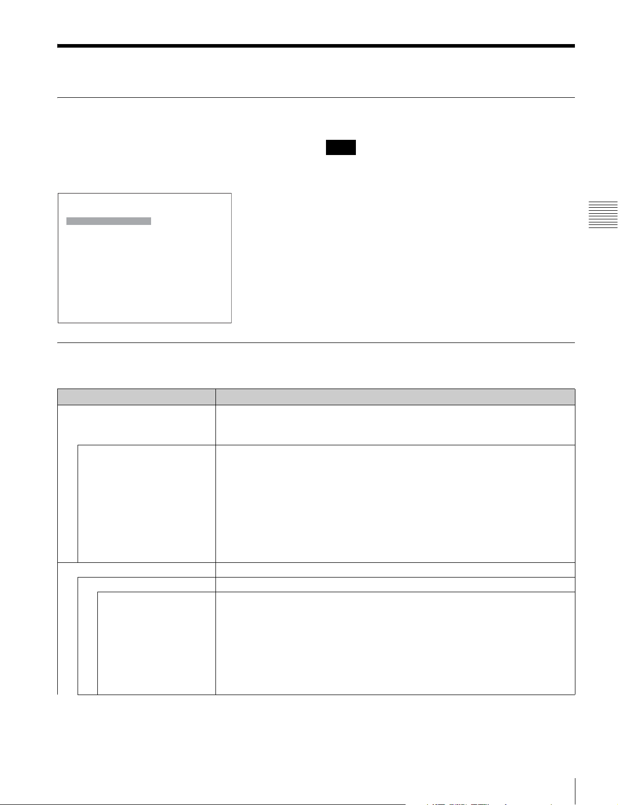
File Management Menu
Overview
The system data is saved, copied and deleted.
When File Management is selected, the following menu is
displayed.
Note
Use the controller with software version 1.6 or higher to
use the File Management function.
iFile Management
Save To B
Copy From B
Delete B
Data Maintenance B
Menu Function and Operation
Menu Function and operation ([ ]: factory setting)
Save To Saves the data in the “Memory Stick”.
Note
Use the “Memory Stick” after formatting.
Memory Stick Saves the data in the “Memory Stick”.
When the item is selected, you can select the file to save data, or create a new file name.
New Name: Enter a new name of the new file (1 to 20 characters).
Existed file name: Select the file to save data.
The following message appears.
Overwrite this file?
OK: To overwrite the data, press the ENTER (Ent) button.
Cancel: To cancel, press the MENU button.
Note
When a new name is entered, the “.” must not be used as the first character.
Copy From Copies the data.
Other Monitor Selects the data of other monitor.
Monitor ID Enter the ID number of the source monitor.
When the NETWORK switch is set to PEER TO PEER, this is not selectable.
When the ID number is entered, you can select the data to be copied.
All: Copies all data.
Picture Preset: Copies the picture preset data.
Color Temp: Copies the color temperature data.
CH Memory: Copies the channel memory data.
Marker: Copies the preset data of the marker.
System: Copies the system data.
Chapter 3 Menu
File Management Menu
87
Page 88
Menu Function and operation ([ ]: factory setting)
Memory Stick Selects the data in the source “Memory Stick”.
When the item is selected, the file names in the “Memory Stick” are displayed.
When the item is selected, you can select the data to be copied.
Copy From
Delete Deletes the file in the “Memory Stick”.
Memory Stick Deletes the file in the “Memory Stick”.
Chapter 3 Menu
Data Maintenance Does maintenance the system data.
Back Up System Data Writes the data to the “Memory Stick” as the backup data.
Restore System Data Reads the data from the “Memory Stick”.
All: Copies all data.
Picture Preset: Copies the picture preset data.
Color Temp: Copies the color temperature data.
CH Memory: Copies the channel memory data.
Marker: Copies the preset data of the marker.
System: Copies the system data.
When the item is selected, the file names in the “Memory Stick” are displayed.
When the file is selected, the following message appears.
Delete this file?
OK: To delete the data, press the ENTER (Ent) button.
Cancel: To cancel, press the MENU button.
The “In progress x” is displayed and “x” flashes during data writing. (It may take some time
to write the data.)
When the item is selected, the following message appears.
All data will be restored
and monitor will restart
Are you sure?
OK: To continue, press the ENTER (Ent) button.
Reads the data from the “Memory Stick” and automatically restarts the monitor.
Cancel: To cancel, press the MENU button.
Returns to the Data Maintenance menu.
File Management Menu
88
Page 89
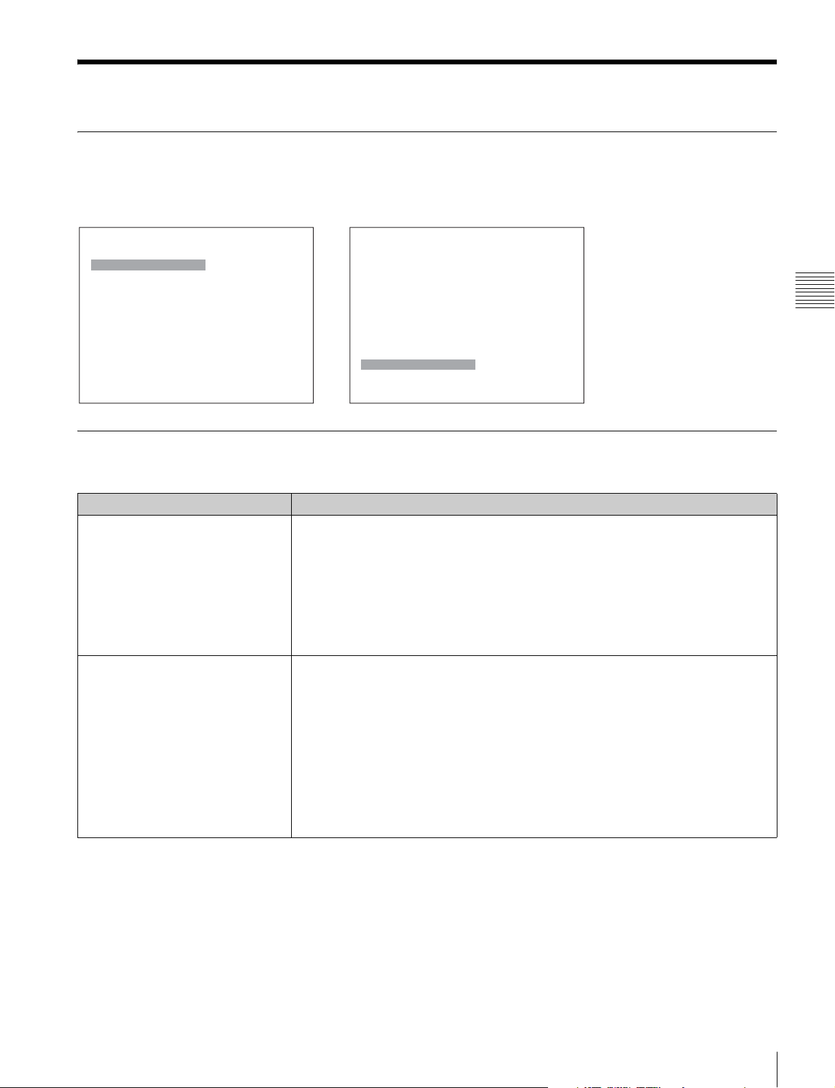
System Status Menu
Overview
This menu is used to view general data about the monitor status, current channel, etc.
When System Status is selected, the following menus are displayed.
iSystem Status 1/2
CH Status B
Port Status
Option1 HD/SD-SDI B
Option2 SD-SDI B
Option3 Composite B
Option4 Component B
SDI Payload ID Status B
HDMI/DP Status B
v
V
iSystem Status 2/2
Model Name: B xxxxx
Serial No: B xxxxx
Software Version: xxxxx
Operation Time: xxxxx
Panel On Time: xxxxx
Network Switch: xxx
Controller Status B
v
V
Menu Function and Operation
Menu Function and operation ([ ]: factory setting)
CH Status Displays the information on the used channels.
The information of the internal signal assigned to the channel number is displayed on the
channels 91 to 97.
CH: Channel number
Por: Port number
Inp: Input connector number
Format: Input signal format
Name: Channel name
For details on the assigned signal, see “Channel numbers 91 to 97 assignment” on page 43.
Port Status
Option1 to Option4
Displays the type of input adaptor installed in Option1 to Option4.
SD-SDI: When BKM-220D is installed
Composite: When BKM-227W is installed
Component: When BKM-229X is installed
HD/SD-SDI: When BKM-243HS or BKM-244CC is installed
3G/HD/SD-SDI: When BKM-250TG is installed
Empty: When the adaptor is not installed
Unknown: When non-supported adaptor is installed
When the item is selected, the model name and serial number of the installed input adaptor
are displayed.
Model Name: Model name
Serial No: Serial number
Chapter 3 Menu
System Status Menu
89
Page 90
Menu Function and operation ([ ]: factory setting)
SDI Payload ID Status Displays the information of the Payload ID data superimposed on the SDI signal and current
signal status of the monitor.
When the option port number in which the BKM-250TG is installed is selected in Input Port of
the Channel Configuration menu, the following is displayed.
OptionX/InputX: Input port and input connector of the displayed information
Standard or Option1 to 4 is displayed as an input port, and Input1 or Input2 is displayed
as an input connector.
Payload ID: XX XX XX XX (4-byte data for Payload ID of the SMPTE-352M standard)
Displays the 4-byte data in hexadecimal in sequence of Byte 1, Byte 2, Byte 3 and
Byte 4.
When the Payload ID information is not set, only Current Status is displayed and “---” is
displayed for other items. When the following information is not decoded, Unknown is
displayed.
Video Standard: Decode display of Byte 1_Bit 6-0 (SD-SDI/HD-SDI/3G-SDI/Dual
Link HD-SDI, etc.)
Chapter 3 Menu
You can confirm the same information using the Status button on the controller. For details,
see “Displaying the Monitor Status Page” (page 108).
HDMI/DP Status Displays the signal information of the HDMI or DisplayPort signal.
Notes
• When HDMI/DisplayPort Auto is set to On in the Matrix menu of the Channel Configuration
• When HDMI/DisplayPort Auto is set to On in the RGB Range menu of the Channel
You can confirm the same information using the Status button on the controller. For details,
see “Displaying the Monitor Status Page” (page 108).
Model Name Displays the model name of the monitor.
Serial No Displays the serial number of the monitor.
Software Version Displays software version of the monitor.
Operation Time Displays operation time (hours, in total) of the monitor.
Panel On Time Displays brighten time (hours, in total) of the panel.
Network Switch Displays the NETWORK switch setting.
Controller Status Displays information on the controller.
Model Name Displays the model name.
Serial No Displays the serial number.
Software Version Displays software version.
Network Switch Displays the NETWORK switch setting.
Sampling Structure: Decode display of Byte 3_Bit 3-0 (4:2:2 Y/Cb/Cr / 4:4:4 Y/Cb/
Cr / 4:4:4 G/B/R, etc.)
Bit Depth: Decode display of Byte 4_Bit 1-0 (8bit/10bit/12bit)
Picture Rate: Decode display of Byte 2_Bit 3-0 (23.98/24/25/29.97/30/50/59.94/60)
Scanning Method: Decode display of Byte 2_Bit 7/decode display of Byte 2_Bit 6
(Interlace/Progressive, Progressive/Progressive, etc.)
Link Number: Decode display of Byte 4_Bit 7-6 (Single/Link_1 / Link_2 / Link_3 /
Link_4)
Current Status: Current status of the monitor
Format: Displayed as “Video Standard + Sampling Structure + Bit Depth”
Video Standard: 3G/DL/HD/SD
Sampling Structure: 422 YCbCr/444 YCbCr/ 444 RGB/444 XYZ
Bit Depth: 10/12
I/PsF/P: Interlace/PsF/Progressive
Pixel Encoding: RGB 4:4:4/YCbCr 4:4:4/YCbCr 4:2:2
Color Depth: 8bit/10bit/12bit (HDMI signal), or 6bit/8bit/10bit/12bit (DisplayPort signal)
Matrix: ITU-R BT.601/ITU-R BT.709
RGB Range: Limit/Full
menu, the Matrix status is displayed.
Configuration menu, the RGB Range status is displayed.
System Status Menu
90
Page 91
Controller Menu
Overview
This menu is for the network setting and assigning the function to the function button of the controller.
When Controller is selected, the following menu is displayed.
iController
Network B
Function Key B
Monitor ID Display: xxx
Controller Upgrade B
Menu Function and Operation
Chapter 3 Menu
Menu Function and operation ([ ]: factory setting)
Network Sets the remote control function of the network.
For the setting value, consult the network administrator.
Network Setting Sets the IP address, subnet mask and default gateway.
IP Address Sets the IP address. [192.168.000.100]
Note
When the NETWORK switch is set to PEER TO PEER, the IP address is set to
“192.168.0.100” regardless of the display.
When the NETWORK switch is set to LAN, the IP address is set to the displayed one.
Subnet Mask Sets the subnet mask. [255.255.255.000]
Note
When the NETWORK switch is set to PEER TO PEER, the subnet mask is set to
“255:255:255:000” regardless of the display.
When the NETWORK switch is set to LAN, the subnet mask is set to the displayed one.
Default Gateway Sets whether or not to set the default gateway ([Off] or On).
Address Sets the address of the default gateway. [---.---.---.--- (no setting)]
Cancel Cancels the changed or confirmed setting.
Confirm Saves the changed or confirmed setting.
SNMP Setting Sets SNMP.
For the setting value, consult the network administrator.
Contact Sets the information of the administrator.
When the item is selected, you can enter a new name.
New Name: Enter a new name (up to 20 characters).
Name Sets the information for the administration (device ID).
When the item is selected, you can enter a new name.
New Name: Enter a new name (up to 20 characters).
Controller Menu
91
Page 92
Menu Function and operation ([ ]: factory setting)
Location Sets the location information.
When the item is selected, you can enter a new name.
Network
Trap Sets the address to send the information.
Mode Sets the settings to send information manually or automatically ([Manual] or Auto).
Trap Address Setting Sets the IP address to send the information. [000.000.000.000]
Chapter 3 Menu
Trap Address Status Displays the IP address to send the information.
Reset Mode/Address Resets the settings to send information manually or automatically and the IP address to the
Authentication Sets whether or not to issue the authentication ([Disable] or Enable).
Community Sets the community name.
Protocol Setting Sets the required items for communications such as the port number.
SDCP/SDAP Community Sets the SDCP/SDAP community name.
SDCP Port No Sets the SDCP port number.
SDAP Port No Sets the SDAP port number.
SDAP Broadcast Sets whether or not to issue the SDAP (Disable or [Enable]).
SDAP Broadcast Period Sets the period (seconds) to issue the SDAP.
Reset Protocol Setting Resets the protocol setting.
Function Key Assigns the function to the function buttons of the controller.
New Name: Enter a new name (up to 20 characters).
This item cannot be selected when the monitor is controlled with BKM-15R or BVM-A14F5.
When Mode is set to Manual or the monitor is controlled with BKM-15R or BVM-A14F5, you
can select this item.
When the item is selected, you can set the IP address of Trap1 to Trap4.
When the monitor is controlled with BKM-15R or BVM-A14F5, you can set only the IP
address of Tra p1 and Trap2.
Cancel: Cancels the changed or confirmed setting.
Confirm: Saves the changed or confirmed setting.
When Mode is set to Auto, you can select this item.
This item cannot be selected when the monitor is controlled with BKM-15R or BVM-A14F5.
When the item is selected, the IP address of Tr ap 1 to Trap4 is displayed.
factory setting.
This item cannot be selected when the monitor is controlled with BKM-15R or BVM-A14F5.
When the item is selected, the following message appears.
Are you sure?
OK: To reset the data, press the ENTER (Ent) button.
Cancel: To cancel, press the MENU button.
This item cannot be selected when the monitor is controlled with BKM-15R or BVM-A14F5.
This item cannot be selected when the monitor is controlled with BKM-15R or BVM-A14F5.
When the item is selected, you can enter the community name (up to 20 characters).
public: Initially, public is entered automatically. Enter any character after it.
New Name: Enter a community name.
This item cannot be selected when the monitor is controlled with BKM-15R or BVM-A14F5.
For the setting value, consult the network administrator.
When the item is selected, you can enter the community name (four characters).
SONY: SONY is entered as a community name.
New Name: Enter a new name.
Set to 53434 to 53534. [53484]
Set to 53812 to 53912. [53862]
Set to 05 to 30. [30]
When the item is selected, the following message appears.
Are you sure?
OK: To reset data, press the ENTER (Ent) button.
Cancel: To cancel, press the MENU button.
This item cannot be selected when the monitor is controlled with BKM-15R or BVM-A14F5.
For details on the function assignment, see “Assigning a Function to a Function Button” (page
110).
92
Controller Menu
Page 93
Menu Function and operation ([ ]: factory setting)
F1 to F16 The following functions are assigned.
Scan Mode: Changes the scan mode of the picture.
Native Scan: Displays the picture in native scan mode.
16:9: Changes the aspect ratio to 16:9 or 1.896:1 (digital cinema signal), and when set to
Function Key
Off, the aspect ratio changes to 4:3 or 2.39:1.
The aspect ratio of some signals is fixed to 16:9 depending on the signal format. For
details, see “Available Signal Systems” on page 122.
H Delay: The picture moves horizontally and a horizontal sync signal appears.
• Brightness of the picture increases automatically, and it makes it easy to check the
sync part.
• When V DELAY button is set to on in H delay mode, a pulse cross picture is displayed.
V Delay: The picture moves vertically and a vertical sync signal appears approximately
in the center of the screen.
• Brightness of the picture increases automatically, and it makes it easy to check the
sync part.
• When H DELAY button is set to on in V delay mode, a pulse cross picture is displayed.
External Sync: Sets whether or not to set to the external sync mode when the analog
component signal or analog RGB signal is input. When the button is set to on, the signal
to be displayed is synchronized with the sync signal input to the EXT SYNC connector
(External Sync). When set to off, the signal to be displayed is synchronized with the sync
signal included in the signals being monitored (Internal Sync).
Note
When the button is set to off (Internal Sync), a sync signal is added on the Y signal to
monitor the analog component signal and on the G signal to monitor the analog RGB
signal.
Comb: The comb filter is turned on.
When the button is set to off, the trap·band-pass filter is selected.
When the displayed signal is NTSC, PAL or PAL-M, this functions.
You can select the kind of the comb filter in the NTSC Comb Filter menu (page 68) of the
Auxiliary Setting menu.
Char Off: The characters on the monitor screen hide during manual adjustment.
Color Temp: You can access directly the Manual Adjust menu of the Color Temp Adj
menu.
Status: Various status information regarding the monitor are displayed on a single page.
For details on the display, see “Displaying the Monitor Status Page” (page 108).
Note
Use the controller with software version 1.6 or higher to assign Status to a function
button of the controller.
Aperture: When the function is set to on, the frequency response can be modified. The
degree of modification is set in the Aperture Value menu (page 68) of the Auxiliary
Setting menu.
For information about the aperture modification frequency for each signal system, see
“Aperture Modification Frequency” on page 132.
Mono: When the button is set to on, a monochrome picture is displayed. When the
button is set to off, the monitor switches automatically between color and monochrome
mode, depending on the color discrimination of the input adaptor.
Blue Only: Red and green signals are cut, and only the blue signal is displayed as a
monochrome picture. It makes it easy to adjust chroma and phase, and to check VTR
noise.
R Off: R (red) signals are cut respectively.
G Off: G (green) signals are cut respectively.
B Off: B (blue) signals are cut respectively.
Chroma Up: The chroma setting increases by 12 dB.
Interlace: Displays in the interlace mode.
Pixel Zoom: The part of the picture is magnified up to 8 times.
Capture Load: Displays the menu to load the captured picture from the “Memory Stick”.
Marker: All markers are displayed on the screen.
Aspect Marker: An aspect marker is displayed on the screen.
Chapter 3 Menu
Controller Menu
93
Page 94
Menu Function and operation ([ ]: factory setting)
Area Marker1: An area marker 1 is displayed on the screen.
Area Marker2: An area marker 2 is displayed on the screen.
Center Marker: The center marker is displayed on the screen.
Aspect Marker-Line: The line of the aspect marker is displayed on the screen.
Function Key
Chapter 3 Menu
Monitor ID Display Sets display mode of the display window.
Aspect Blanking-Half: Aspect Blanking is set to half blanking.
Aspect Blanking-Black: The blanking level of Aspect Blanking is set to 0% black level.
Note
Use the controller with software version 1.6 or higher to assign Center Marker, Aspect
Marker-Line, Aspect Blanking-Half or Aspect Blanking-Black to a function button of the
controller.
Side by Side: The screen is displayed in the side by side display mode.
Wipe: The screen is displayed in the wipe display mode.
Butterfly: The screen is displayed in the butterfly display mode.
Blending: The screen is displayed in the blending display mode.
Error Notify Clear: Clears the notification detected in the gamut error detection. (OSD
Notification)
Audio Level Meter: The audio level meter is displayed.
ALM Hold Reset: The peak hold of the audio level meter is canceled.
Time Code: The time code is displayed.
Note
Use the controller with software version 1.4 or higher to assign Audio Level Meter, ALM
Hold Reset or Time Code to a function button of the controller.
Difference: The difference between the luminance of the left 3D video signal and that of
the right signal is displayed.
Note
Use the controller with software version 1.6 or higher to assign Difference to a function
button of the controller.
Checkerboard: The left and right 3D video signals are displayed in a checkerboard
pattern.
L/R Switch: The left and right 3D video signals are displayed alternately by switching.
Note
Use the controller with software version 1.5 or higher to assign Checkerboard or L/R
Switch to a function button of the controller.
Horopter Check: The left and right 3D video signals are displayed in the mode selected
in Horopter Check (page 74) in the 3D Setting menu of the Function Setting menu.
Flip H: The 3D video signals are inverted horizontally and displayed.
Note
Use the controller with software version 1.6 or higher to assign Horopter Check or Flip H
to a function button of the controller.
Black Frame Insertion: The signal is displayed in black frame insertion mode (only for
BVM-L and PVM-L series).
Black Detail Mode: The signal is displayed in black detail mode (only for BVM-L and
PVM-L series).
Note
Use the controller with software version 1.3 or higher to assign Black Detail Mode to a
function button of the controller.
Degauss: The CRT is degaussed (only for BVM-A series).
[On]: Always displayed.
Auto: Displayed during operating by the remote connection and disappears
automatically after operation.
Off: Not displayed.
94
Controller Menu
Page 95
Menu Function and operation ([ ]: factory setting)
Controller Upgrade Upgrades the controller.
When the item is selected, the screen for inputting the password is displayed.
After the 4-digit password is entered, the current versions of Software Version and Kernel
Version are displayed.
For the password, see Password (page 84) of the System Configuration menu.
For details on upgrading the controller, see “Upgrading the Monitor and Controller” on page
111.
Software Upgrade Upgrades the software for the controller.
Kernel Upgrade Upgrades the kernel of the controller.
Chapter 3 Menu
Controller Menu
95
Page 96
Key Protect Menu
Overview
This menu is used to lock the data so that the setting is not changed by an unauthorized user.
MENU
Adjustment B
Channel Configuration
Auxiliary Setting B
Function Setting B
System ConfigurationB
Chapter 3 Menu
File Management B
System Status B
Controller B
Key Protect: Off
Menu Function and Operation
B
Menu Function and operation ([ ]: factory setting)
Key Protect Sets the key protection.
On: The button on the controller (except the menu operation buttons and monitor
selection buttons) and the parallel remote do not function and other settings are not
changeable.
[Off]: Release the lock.
96
Key Protect Menu
Page 97
Operations
Selecting Display Mode
This monitor applies high-contrast to the picture and
reproduces accurate color by displaying the interlace
signal in progressive mode by the I/P conversion or the
PsF·progressive signal in progressive mode without the
I/P conversion.
You can select interlace display mode according to the
input signal or the object to evaluate the picture.
Interlace display mode: The picture is displayed in
interlace mode without I/P conversion processing. The
picture near the original quality of the input signal is
monitored.
Notes
• When a 1080/24
signal is displayed in progressive mode, the frame rate
for display is 72
display.
• When the input signal is 1080/24
and 1080I is set in the 1080I/PsF menu of the Channel
Configuration menu, the frame rate for display is 48
Hz or 50 Hz.
• The luminance is reduced owing to the principle of
operation in the interlace display mode. However, on
this monitor the normal luminance is set by increasing
the value of gain. For this reason, in the interlace display
mode, the range of the contrast adjustment is different
from the normal level, and the luminance may be
reduced according to the setting of the contrast.
• The picture is not displayed in interlace mode in the
following cases:
– When Side by Side, Wipe, Butterfly or Blending is
set to On
– When Pixel Zoom is set to on
1)
P (PsF) or 1080/25P (PsF) input
1)
Hz or 75 Hz to obtain flickerless
1)
PsF or 1080/25PsF
Chapter
2
Set Interlace to On in the Function Switch menu (page
75) of the Function Setting menu, or pressing the
Interlace button
iiFunction Switch 2/5
Aperture: xxx
Mono: xxx
Blue Only: xxx
R Off: xxx
G Off: xxx
B Off: xxx
Chroma Up: xxx
Interlace: xxx
For the input signal to display in frame mode and
interlace mode, see “Picture Frame Display” on
page 136.
1) Also compatible with a frame rate of 1/1.001.
2) Interlace is assigned to a function button of the controller in the Function
Key menu (page 92) of the Controller menu.
1)
2)
on the controller.
4
v
V
Chapter 4 Operations
1
For selecting the interlace display mode, set Native
Scan (page 75) to On in the Function Setting menu or
by pressing the NATIVE SCAN button of the
controller.
Selecting Display Mode
97
Page 98
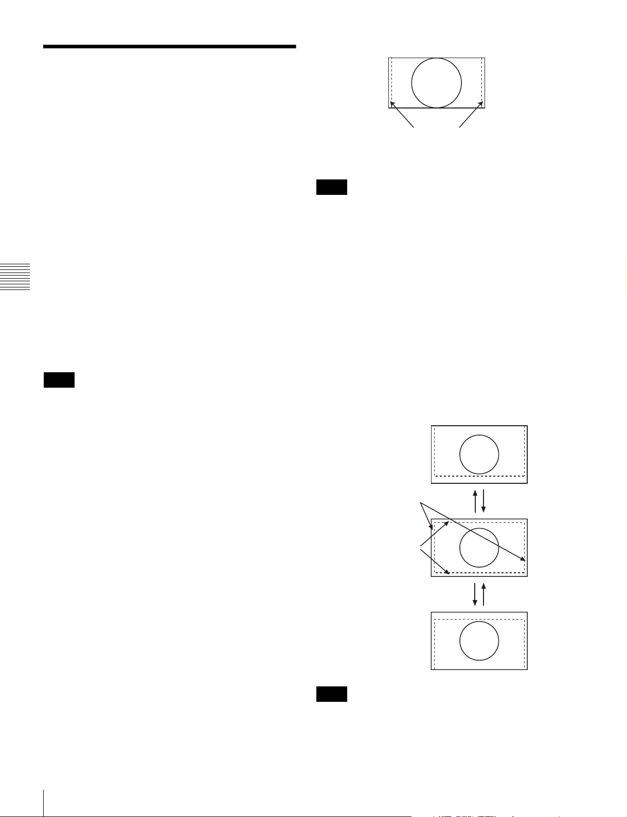
Setting the Display of Native Scan Mode
About the native scan mode
You can set the picture display type for the native scan
mode according to the input signal.
You can select ×1 or ×2, which differ in picture display
size, to map the pixels of the signal to the panel in one-toone mode, or Aspect Correction. An SD signal of nonsquare pixels (the number of H pixels of the signal system
is 720 or 1440) or a 640 × 480 SD signal of
HDMI/DisplayPort video is displayed correctly by scaling
processing of doubling for the V direction and correct
aspect ratio for the H direction, and the picture is also
optimized and displayed by modifying the aperture
coefficient value, filter coefficient value, etc. in Aspect
Chapter 4 Operations
Correction mode.
For details, see “Picture Display Size” on page 134.
Set the native scan mode in the Native Scan Mode menu
(page 68) of the Auxiliary Setting menu.
Note
The native scan is not selectable in the following cases:
• When the input signal has no sync signal
• When Side by Side is set to On
• When Pixel Zoom is set to on
• When the HDMI/DisplayPort computer signal is input
(The native scan is displayed regardless of the setting.)
• When a digital cinema signal (2048 × 1080) is input and
the internal signal is displayed (Native Scan is set to Off
and the normal scan is displayed regardless of the
setting.)
• When the signal system is the SD signal of 720 × 576 or
1440 × 576, Native Scan Mode is set to Aspect
Correction or ×2 and the internal signal displayed
(Native Scan is set to Off and the normal scan is
displayed regardless of the setting.)
Displayed by sliding the picture
with the PHASE knob of the
controller.
Note
The set position is held even when the system is changed to
another input signal system.
Display of the input signal system 576/50i
or 576/50P
When the input signal system is the SD signal of 720 × 576
or 1440 × 576 and Native Scan Mode is set to ×2 or Aspect
Correction, you can display no display area of the upper
and lower sides over the V size (1080) by sliding the
picture with the UP/DOWN button of the controller.
And when the input signal is same as above and Native
Scan Mode is set to Aspect Correction and the aspect ratio
is 16:9, you can display no display area of the left and right
sides over the H size (1920) by sliding the picture with the
PHASE knob of the controller. You can restore the display
position to the center by pressing the MANUAL button of
PHASE of the controller.
Displayed the whole picture
of the H direction by sliding
the picture with the PHASE
knob of the controller.
Displayed the whole
picture of the V direction
by sliding the picture with
the UP/DOWN button of
the controller.
UP button DOWN button
Display of the input signal system 2048 ×
1080
When the input signal system is 2048 × 1080 and the native
scan mode is selected, you can display no display area of
the left and right sides over the H size (1920) by sliding the
picture with the PHASE knob of the controller. You can
restore the display position to the center by pressing the
MANUAL button of PHASE of the controller.
Setting the Display of Native Scan Mode
98
UP buttonDOWN button
Note
The set position is held even when the system is changed to
another input signal system.
Page 99
Over Scan: Over mode
Selecting the Native Scan/Scan Mode
You can select scan mode from a native scan, under scan
(–3%), normal scan (0%) and over scan (mask of 5% over
scan portion in the normal scan picture).
You can set scan mode with the NATIVE SCAN button or
SCAN button of the controller, or in the Function Switch
menu of the Function Setting menu.
Setting with the NATIVE SCAN button or
SCAN button of the controller
To set to the native scan mode
Set the NATIVE SCAN button to on. (The LED on the
button lights.)
To select the scan mode
1
Set the NATIVE SCAN button to off. (The LED on
the button is turned off.)
2
Press the SCAN button to select the scan mode.
Note
The scan mode is not selectable in the following cases:
• When Native Scan is set to On
• When the internal signal is displayed
• When Side by Side, Wipe, Butterfly or Blending is set to
On
Chapter 4 Operations
Scan mode is changed to normal, under and over scan
mode by each press of the button.
Setting in the menu
Set Scan Mode or Native Scan in the Function Switch
menu (page 75) of the Function Setting menu.
iiFunction Switch 1/5
Scan Mode: xxx
Native Scan: xxx
16:9: xxx
H Delay: xxx
V Delay: xxx
External Sync:: xxx
Comb: xxx
To set to the native scan mode
Set Native Scan to On.
To select the scan mode
1
Set Native Scan to Off.
v
V
2
Select Scan Mode, then select scan mode from the
following.
Normal Scan: Normal mode
Under Scan: Under mode
Selecting the Native Scan/Scan Mode
99
Page 100
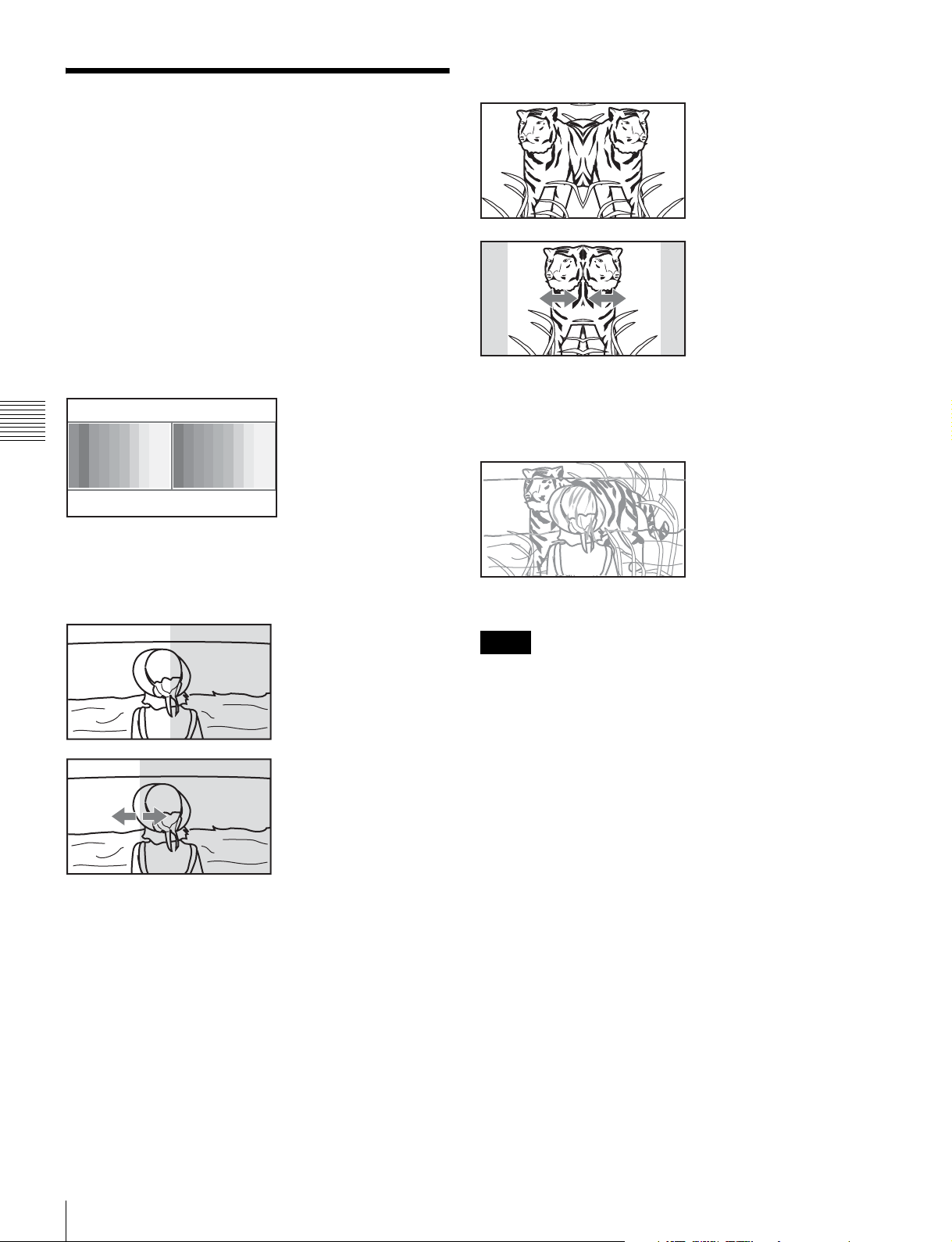
Butterfly (butterfly)
Displaying Two Signals on One Screen (Picture&Picture)
Two input signals are output on the monitor. You can
select the display mode from Side by Side (side by side),
Wipe (wipe), Butterfly (butterfly) and Blending
(blending). This is useful for adjusting the color or
comparing two pictures.
You can input the file loaded in the Capture menu (page
74) of the Function Setting menu.
Side by Side (side by side)
Two pictures are
displayed side by side.
Chapter 4 Operations
Signal A Signal B
The right picture is a left-right
reversal picture of the left
picture.
The display range of the
picture is changed with the
PHASE knob of the
controller.
Signal A Signal B
Blending (blending)
A picture that superimposes
signal A and signal B is
displayed.
The mixed ratio of two input
signals is changed with the
PHASE knob of the
controller.
Wipe (wipe)
Signal A Signal B
Left and right pictures
connected at the boundary
position are displayed.
The boundary line of the left
and right area is changed
with the PHASE knob of the
controller.
Signal A and Signal B
Notes
• The input signals from INPUT 1 and INPUT 2 of one
standard SDI input or one input adaptor are not displayed
in the multi display.
• You cannot select the same channel number as channels
for signal A and signal B. And set a different channel
number of the different standard input or input adaptor
for signal A and signal B.
• When the wipe or blending mode is used, signal A and
signal B should be genlocked to synchronize with each
other.
• When signal A and signal B are not the same signal
format and signal system, the pictures may not be
displayed correctly.
• The input of signal A is not changed in the multi display.
• The internal signal is not displayed in the multi display.
• The captured picture data is not used to display as signal
A and signal B at the same time.
• The signals are not displayed in the multi display mode
when Pixel Zoom is set to on.
• The color space and gamma setting for signal A is
applied in the multi display.
• The multi display with an HDMI input signal and a
DisplayPort input signal is not possible.
100
Displaying Two Signals on One Screen (Picture&Picture)
 Loading...