

Page 1
- 1 -
As of May 8, 2012
BRU-SF10
1. Single mode fiber cable supported
The BRU-SF10 supports single mode optical fiber cable ensuring 2,000m transmission at maximum.
2. Status display on the front panel
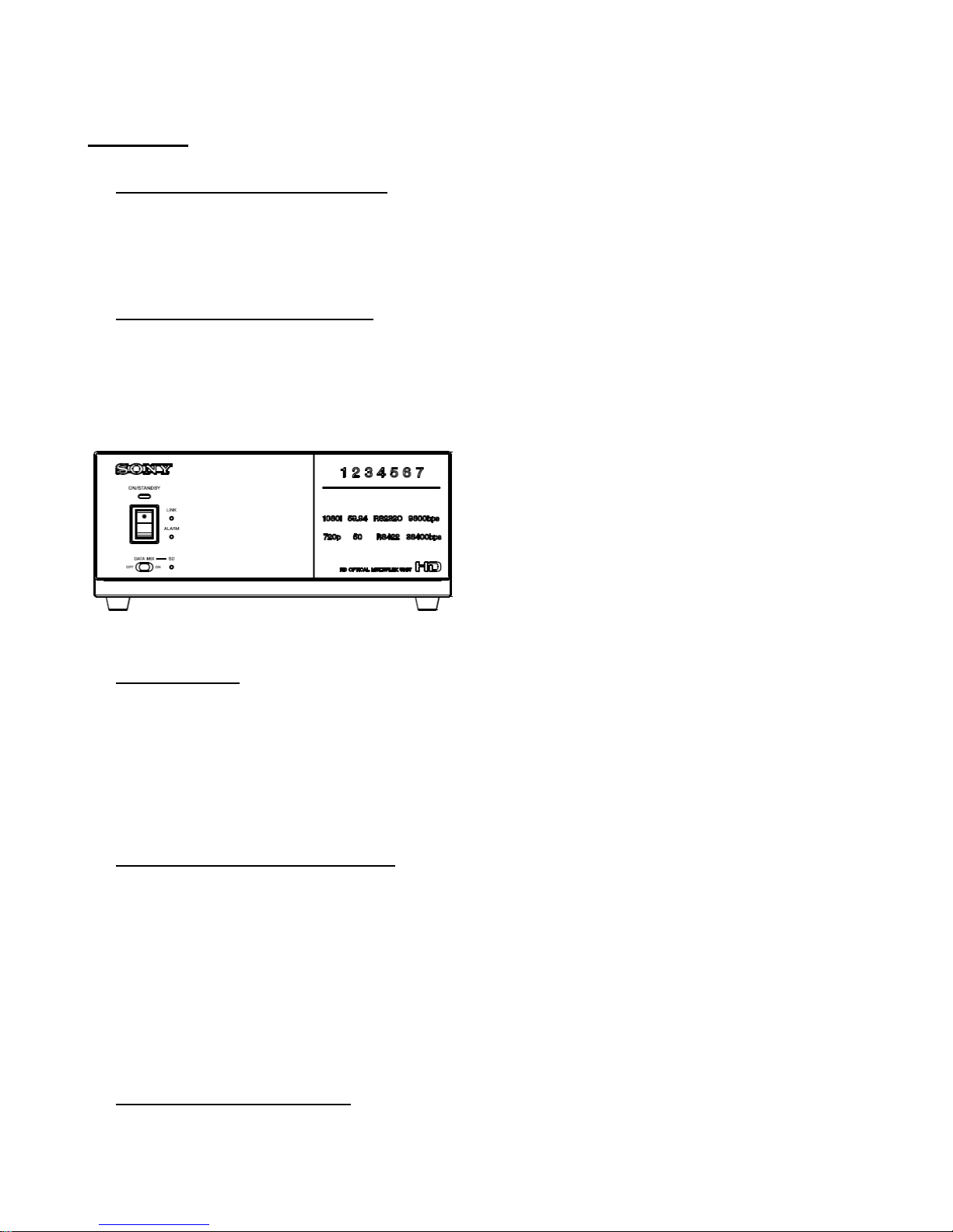
The following various status displays are newly added on the front panel of the BRU-SF10 to increase its usability.
- 1080i/720p, 59.94/50, RS-232C/422, 9600/38400bps
- Camera ID : 1~7
3. Monitor output
By inserting the BRBK-HSD2, the HD/SD-SDI output card into optional card slot, the BRU-SF10 enables monitor
output. By terming off data mix, it enables various camera settings without displaying OSD on video out signal (main
line).
4. Uncompressed digital transmission
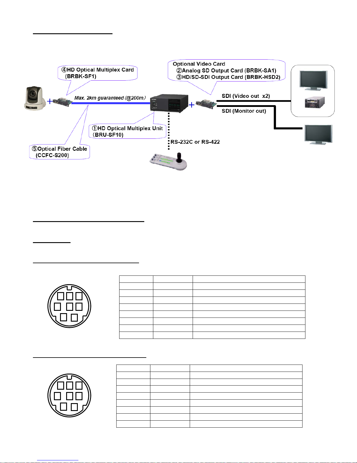
The BRU-SF10 features uncompressed multiple signal operation via a single cable. Video, sync, pan/tilt control,
camera control signal and audio line-in signal can be transmitted using with the CCFC-S200, single mode optical fiber
cable and the BRBK-SF1, HD optical multiplex card. The distance between the BRU-SF10 and the BRC-Z330/-H900
can be extended to a maximum 2,000m (6,560 feet). The Single cable operation makes it possible to integrate the
camera system easily.
5. Variety of video signal output
The BRU-SF10 is equipped with analog RGB or Y/Pb/Pr signal output as standard. Furthermore, 2 built-in optional
Page 2

- 2 -
card slots enable to provide various signals in order to broaden the range of applications. For instance, HD-SDI signal
can be provided when installing the BRBK-HSD2 into the card slot. Two same kinds of cards can be installed into the
BRU-SF10 at the same time.
6. External sync signal input/output equipped
When multiple BRC-Z330 or BRC-H900 HD cameras or combination of BRC-Z330 and BRC-H900 HD cameras are
connected via the Optical Fiber Cable, the video signal can be synchronized by inputting the sync signal into the
external sync input connector.
7. Audio line output connectors (phono jacks, L/R) equipped
The BRU-SF10 allows output of stereo audio line signals that are transmitted from the BRBK-SF1 HD Optical
Multiplex Card inserted into the BRC-Z330/-H900 HD camera.
8. RS-232C/RS-422 serial control by VISCA™
All of camera and pan/tilt functions can be controlled via VISCA commands with a remote controller or a PC. This
unit incorporates the VISCA Mini DIN 8pin connectors for RS-232C control between BRU-SF10 and
BRC-Z330/-H900. Additionally, the dedicated 9pin connector is incorporated for RS-422 control from far location.
While the RS-232C is extended up to 15m (50feet) officially, the RS-422 is up to approximately 1.2km (4,000feet).
The data transmission speed of the RS-422 and the RS-232C can be selected either 9600bps or 38400bps.
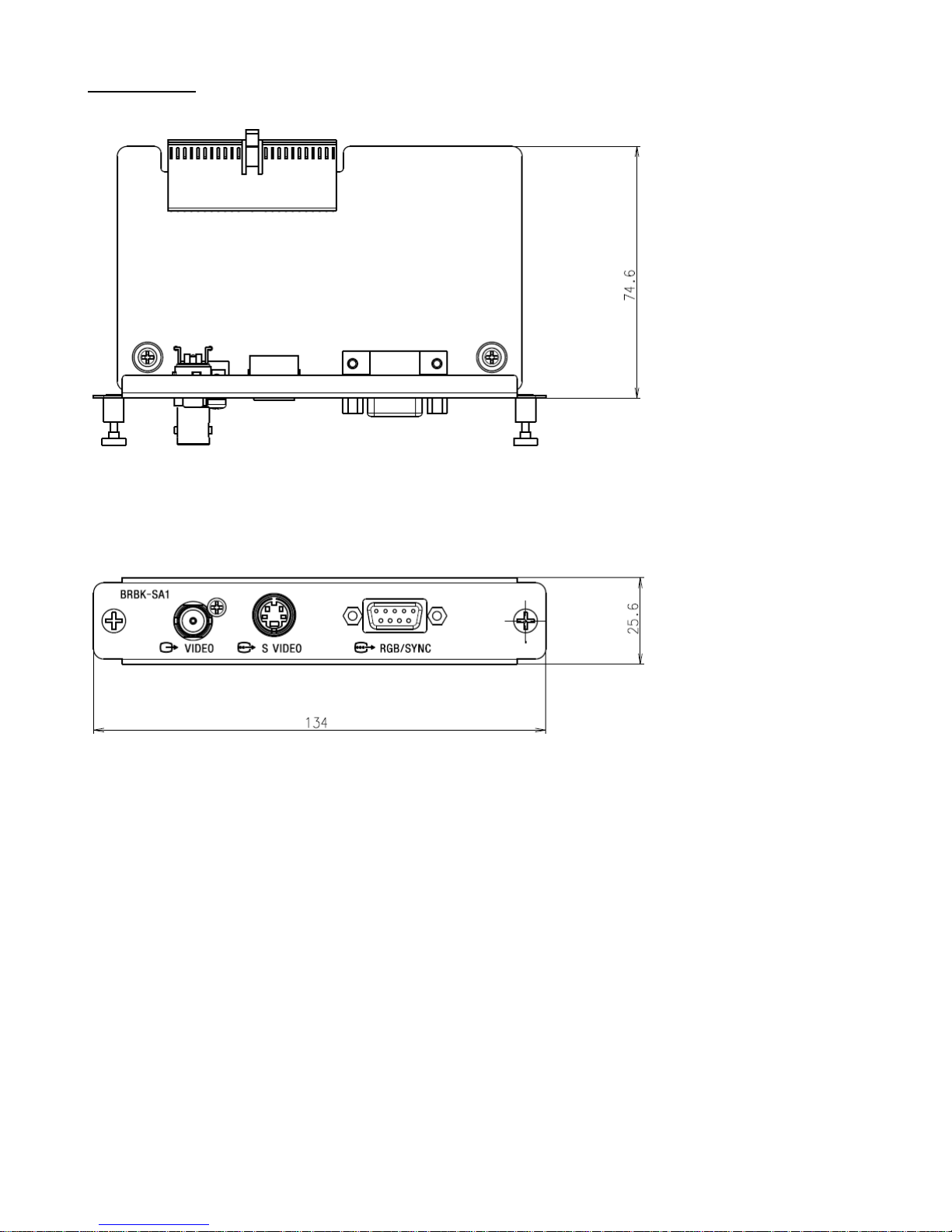
BRBK-SA1
Analog SD output card
The BRBK-SA1 enables down convert to analog SD output signal when installed into the BRU-SF10 built-in card slot.
This can be used as an optional card for the BRC-Z330/-H900*.
*Note: Although the BRBK-SA1 can be used with the BRC-Z330/1, in case of using with previous version of the
BRC-Z330, it requires version upgrade.
Page 3

- 3 -
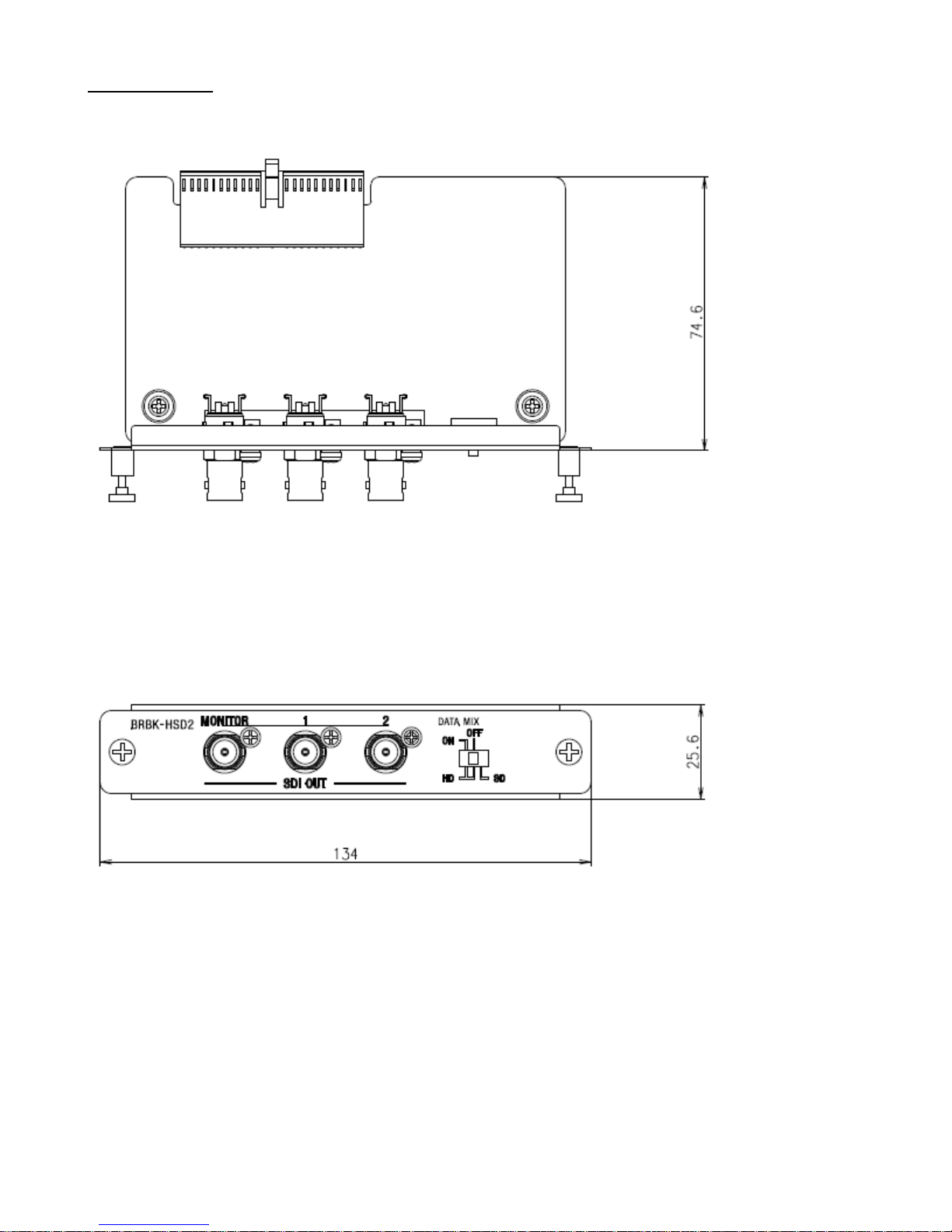
BRBK-HSD2
HD/SD-SDI output card
The BRBK-HSD2 provides HD-SDI signal when installed into the BRU-SF10 built-in card slot. By turning off data
mix, it enables various camera settings without displaying OSD on video out signal (main line). This can be used as an
optional card for the BRC-Z330*/-H900.
Note 1: Although the BRBK-HSD2 can be used with the BRC-Z330/1, in case of using with previous version of the
BRC-Z330, it requires version upgrade.
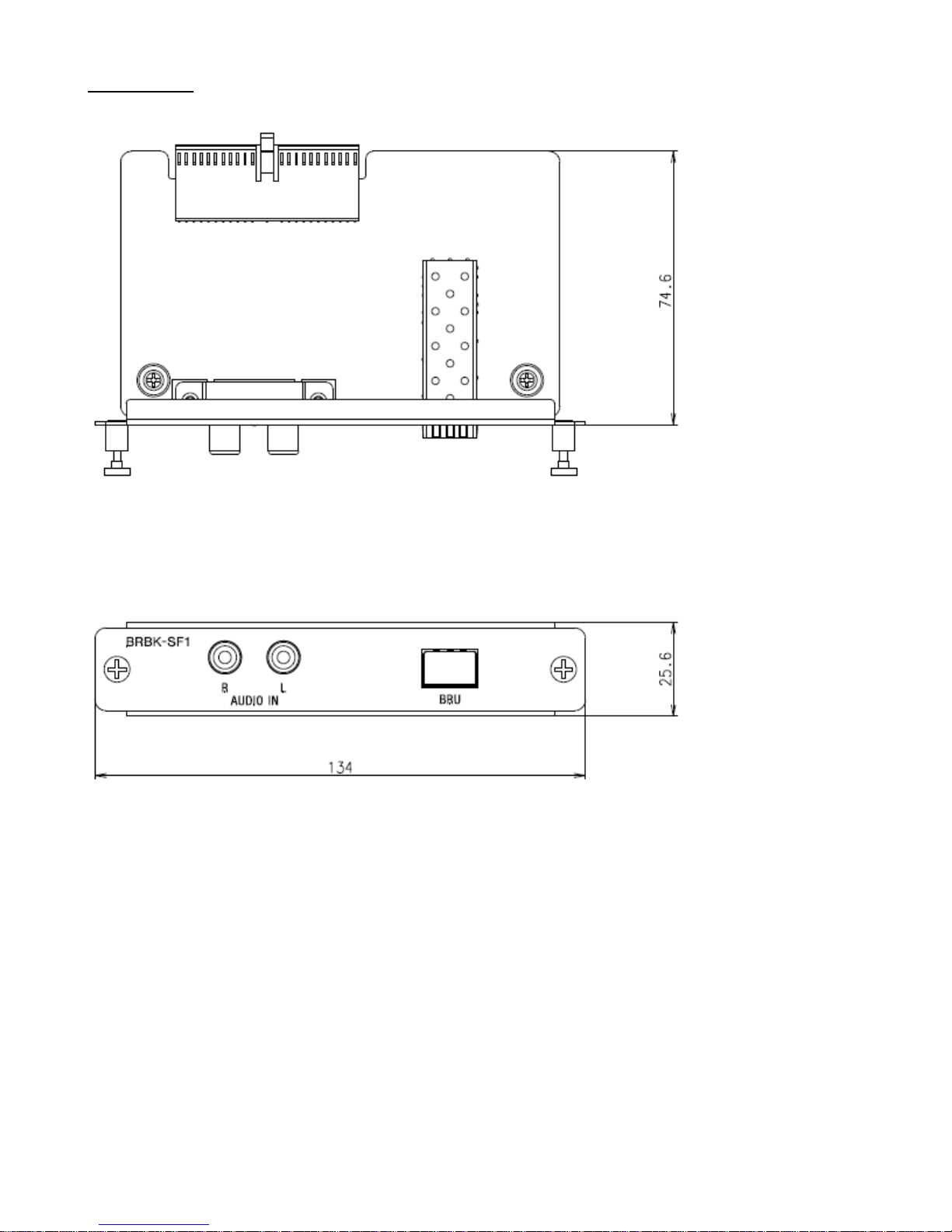
BRBK-SF1
1. HD optical multiplex card
The BRBK-SF1 provides high quality optical multiplex HD signal and audio line-in signal when installed into the
BRC-Z330* /-H900 built-in card slot.
Note: Although the BRBK-SF1 can be used with the BRC-Z330/1, in case of using with previous version of the
BRC-Z330, it requires version upgrade.
2. Audio line input
The BRBK-SF1 is equipped with phono jack for Audio input. By installing the BRBK-SF1 into the BRC-Z330/-H900,
image signal of the BRC-Z330/-H900 and analog audio signal received by the BRBK-SF1 can be simultaneously
transferred to the BRU-SF10 via single mode optical fiber cable. This is effective when a microphone is set near
the BRC-Z330/-H900 located in distant place while the BRU-SF10 located by an operator who needs both image and
audio at the same time.
CCFC-S200
Single mode optical fiber cable
The CCFC-S200 is a single mode optical fiber cable for connecting the BRC-Z330/-H900 (with BRBK-SF1) to the
BRU-SF10. The CCFC-S200 can transmit uncompressed digital data without any deterioration. It can be extended up
to 2000m (6,560 feet) using with supplied cable extension adaptor.
Page 4
- 4 -
System Configurations
(When the BRBK-HSD2 x1 is inserted into the BRU-SF10)
Note: The BRBK-HD2 for the BRC-Z330/-H900 can not be used with the BRU-SF10.
Pin Assignment and Connection
BRU-SF10
VISCA RS-232C IN pin assignment
VISCA RS-232C OUT pin assignment
Pin No.
Name
Signals
1
DTR
Data Transmission Ready (INPUT)
2
DSR
Data Set Ready (INPUT)
3
TXD
Transmit Data (INPUT)
4
GND
Ground
5
RXD
Receive Data (INPUT)
6
GND
Ground
7
N.C.
No Connection
8
N.C.
No Connection
Pin No.
Name
Signals
1
DTR
Data Transmission Ready (OUTPUT)
2
DSR
Data Set Ready (OUTPUT)
3
TXD
Transmit Data (OUTPUT)
4
GND
Ground
5
RXD
Receive Data (OUTPUT)
6
GND
Ground
7
N.C.
No Connection
8
N.C.
No Connection
BRC-Z330/-H900
Page 5
- 5 -
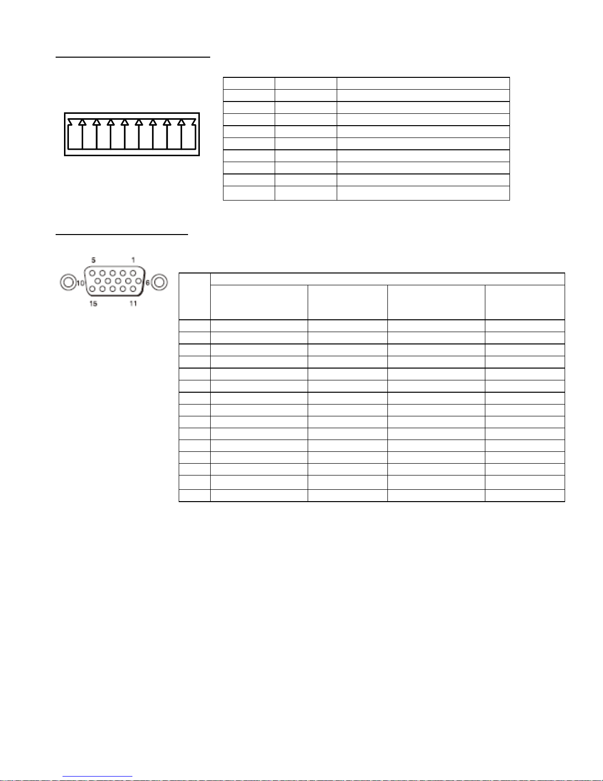
VISCA RS-422 pin assignment
D-Sub 15P pin assignment
Pin No.
Name
Signals
1
RXD OUT-
Receive Data (OUT) -
2
RXD OUT+
Receive Data (OUT) +
3
TXD OUT-
Transmit Data (OUT) -
4
TXD OUT+
Transmit Data (OUT) +
5
GND
Ground
6
RXD IN-
Receive Data (IN) -
7
RXD IN+
Receive Data (IN) +
8
TXD IN-
Transmit Data (IN) -
9
TXD IN+
Transmit Data (IN) +
Pin
No.
Functions
When setting YPbPr
COMPONENT
When setting
COMPONENT
at VD
When setting RGB at
SYNC
When setting
RGB at VD
1
Pr-OUT
Pr-OUT
R-OUT
R-OUT
2
Y-OUT
Y-OUT
G-OUT
G-OUT
3
Pb-OUT
Pb-OUT
B-OUT
B-OUT
4
GND
GND
GND
GND
5
GND
GND
GND
GND
6
GND
GND
GND
GND
7
GND
GND
GND
GND
8
GND
GND
GND
GND
9
NC
NC
NC
NC
10
GND
GND
GND
GND
11
GND
GND
GND
GND
12
NC
NC
NC
NC
13
HD-OUT
HD-OUT
HD-OUT
HD-OUT
14
3 Value SYNC-OUT
2 Value VD-OUT
3 Value SYNC-OUT
2 Value VD-OUT
15
NC
NC
NC
NC
1 2 3 4 5 6 7 8 9
Page 6

- 6 -
Specifications
BRU-SF10 Brochure specifications
Optical fiber
LC Duplex Fiber Connector
Video output
D-Sub 15 pin: Component (Y/Pb/Pr) or RGB, HD, VD or SYNC
External sync input
BNC
External sync output
BNC
Audio line output
Phono jack x2 (L/R)
Camera control
Mini DIN 8 pin: RS-232C (VISCA IN), Mini DIN 8 pin: RS-232C (VISCA OUT),
Connector plug 9 pin: RS-422 (VISCA IN/OUT)
Optional card slots
2 slots
Operating temperature
0 to 40 °C (32 to 104 ºF)
Storage temperature
-20 to 60 °C (-4 to 140 ºF)
Power requirements
12 V DC (10.8 V to 13.2 V DC)
Power consumption
Max. 15.6W (with optional cards)
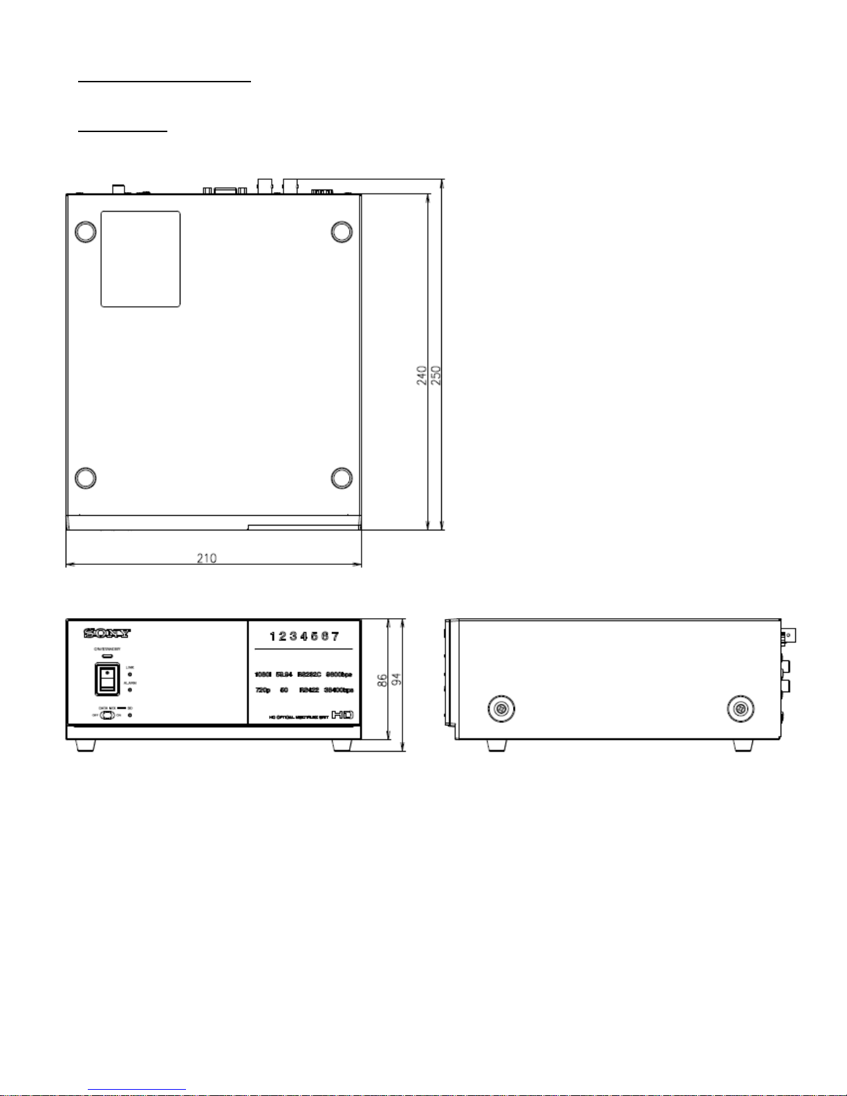
Dimensions (WxHxD)
210 x 86 x 240 mm (8 3/8 x 3 1/2 x 9 1/2 inches)
Mass
2.0kg (4 lb 7oz)
Supplied accessories
AC adaptor (1), Power cord (1), DC-cord secure connection attachment (1), RS-422
connector plug (1), RS-232C connecting cable (3 m, Mini DIN 8 pin) (1), Operating
instructions (1)
BRU-SF10 Additional specifications
Selectable external sync
Standard Sync
RGB three-state Sync
Y three-state Sync
SD Sync
External Sync. Lock capability
Loop Trough Out
BRBK-SA1
Video output
BNC x1: VIDEO,
Mini DIN 4pin x1: S VIDEO,
D-sub 9pin x1: RGB/SYNC
Power supply
12 V DC (supplied from the camera or the Optical Multiplex Unit)
Page 7

- 7 -
Power consumption
3.7 W max.
Operating temperature
0 °C to 40 °C (32 °F to 104 °F)
Operating humidity
20% to 80% (no condensation)
Storage temperature
–20 °C to + 60 °C (–4 °F to +140 °F)
Storage humidity
20% to 95% (no condensation)
Dimensions
134 × 25.6 × 74.6 mm (w/h/d) (5 3/8 × 1 1/16 × 3 inches) (not including the
projected parts)
Mass
Approx. 125g (4.4 oz)
Supplied accessories
Operating instructions (1)
BRBK-HSD2
Video output
BNC x3, HD-SDI or SD-SDI
Power supply
12 V DC (supplied from the camera or the Optical Multiplex Unit)
Power consumption
2.9 W max.
Operating temperature
0 °C to 40 °C (32 °F to 104 °F)
Operating humidity
20% to 80% (no condensation)
Storage temperature
– 20 °C to + 60 °C (–4 °F to +140 °F)
Storage humidity
20% to 95% (no condensation)
Dimensions
134 × 25.6 × 74.6 mm (w/h/d) (5 3/8 × 1 1/16 × 3 inches) (not including the
projected parts)
Mass
Approx. 120g (4.2 oz)
Supplied accessories
Operating instructions (1)
BRBK-SF1
Optical connector
LC duplex Fiber connector (1)
Audio line input
Phono jack, right (1)/left (1)
Power supply
12 V DC (supplied from the camera)
Power consumption
2.9 W max.
Operating temperature
0 °C to 40 °C (32 °F to 104 °F)
Operating humidity
20 % to 80 % (no condensation)
Storage temperature
–20 °C to + 60 °C (–4 °F to +140 °F)
Storage humidity
20 % to 95 % (no condensation)
Dimensions
134 × 25.6 × 74.6 mm (w/h/d) (5 3/8 × 1 1/16 ×3 inches) (not including the
projected parts)
Page 8

- 8 -
Mass
Approx. 130 g (4.6 oz)
Supplied accessories
Operating instructions (1)
CCFC-S200
Type
LC duplex optical fiber cable
Length
200m (656feet)
Weight
Approx. 3.6kg (7lb 15oz)
Supplied accessories
Extension adaptor (1)
Safety approval
BRU-SF10 UC UL+cUL: UL60950-1/CSA C22.2 No.60950-1
FCC/IC: Digital Device Class A
Laser: DHHS/DNHW
BRBK-SA1 WW North America FCC/IC: Digital Device Class A
BRBK-HSD2 WW North America FCC/IC: Digital Device Class A
BRBK-SF1 WW North America FCC/IC: Digital Device Class A
Laser: DHHS/DNHW
Page 9
- 9 -
External appearance
BRU-SF10
Page 10
- 10 -
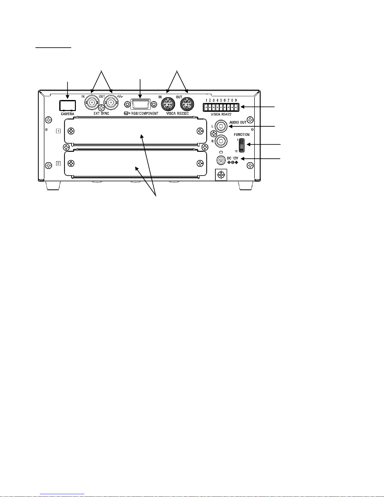
Rear Panel
Option I/F card slots
AUDIO OUT
VISCA RS-422 IN / OUT
VISCA RS-232C IN / OUT
VIDEO OUT D-SUB 15P
External Sync IN / OUT
HD Optical Fiber IN
DC 12 V
DIP SW (10BIT)
Page 11
- 11 -
BRBK-SA1
Page 12
- 12 -
BRBK-HSD2
Page 13
- 13 -
BRBK-SF1
Page 14
- 14 -
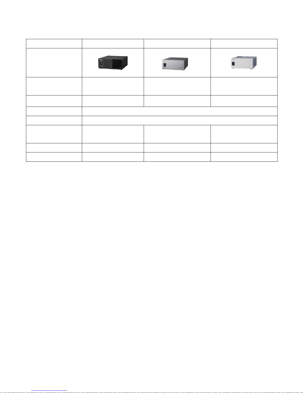
Comparison Chart1
Model name
BRU-SF10
BRU-H700
BRU-300/P
Appearance
Fiber cable Max. extension
2,000m
(CCFC-S200)
1,000m (CCFC-M100HG)
500m (CCFC-M100)
Video output
Analog RGB, Y/Pb/Pr
Analog RGB, Y/Pb/Pr
VBS, Y/C
RS-232C / RS-422
Yes
Sync system
INT/EXT
Power requirements
DC 12 V
59.94i: AC 100 to 120V, 50/60Hz
50i: AC 220 to 240V, 50/60Hz
NTSC: AC 100 to 120V, 50/60Hz
PAL: AC 220 to 240V, 50/60Hz
Power consumption
Max. 15.6W (with optional cards)
Max. 10W (without optional cards)
9W (without optional cards)
Dimensions (WxHxD)
210x86x240
210x86x240
212x88x233
Page 15

- 15 -
CCFC-S200 Specification
1. General information
This specification covers the descriptions of the optical fiber cable with connector.
The following describes the structure and the characteristics of it.
2. Product Name
Nonflammable SM type optical fiber cable with duplex LC connector plug on both sides
3. Cable Name
FR-SMC•10/125•04-2XSF<Cord Color: Yellow, Sheath Color: Black, VW-1>
Cable specification number: JAT-19216B
4. Applicable standard
(1) JIS C 6820 General rules of optical fiber
(2) JIS C 6823 Measurement methods for attenuation of optical fibers
(3) JIS C 6825 Test methods for structure parameter of single mode optical fibers
(4) JIS C 6835 Silica glass single mode optical fibers
5. Environment condition
Storage temperature: -20 degrees to +60 degrees
Operating temperature: -15 degrees to +60 degrees
Storage humidity: Less than 95%RH
Operating humidity: Less than 85%RH
Page 16

- 16 -
6. Structure
6.1 Optical fiber cord
Item
Unit
Construction
Fiber type
-
Single mode (SM) silica glass optical fiber
Mode field diameter
um
9.2±0.7
Cladding diameter
um
125±1
Concentricity error
um
Max. 0.8
Cladding noncircular ratio
%
Max. 2
Interception wavelength
um
1.10~1.29
Fiber curl radius m Min. 2
Proof level
%
Min. 1
Material - UV curable material
Diameter
um
250±15
Reinforcement - Aramid yarn
Jacketing
Material - Flame retardant polyethylene
Color
-
Yellow
Diameter (approx.)
mm
1.5
6.2 Optical fiber cable
Item
Unit
Construction
No. of core
-
2
Optical fiber cord
-
Refer to 6.1
Strength
member
Material - Steel wire
Size
No./mm
1/0.4
No.
-
2
Stranding
-
Arrange optical fiber cords and
strength member as below
Sheath
Material
-
Flame retardant polyethylene
Color
-
Black
Cable diameter
mm
5.8±0.5 x 2.6±0.3
Weight (approx.)
kg/km
17
*”FUJIKURA-S E49075 AWM VW-1 SM” is serially printed on the surface of cable sheath.
Page 17
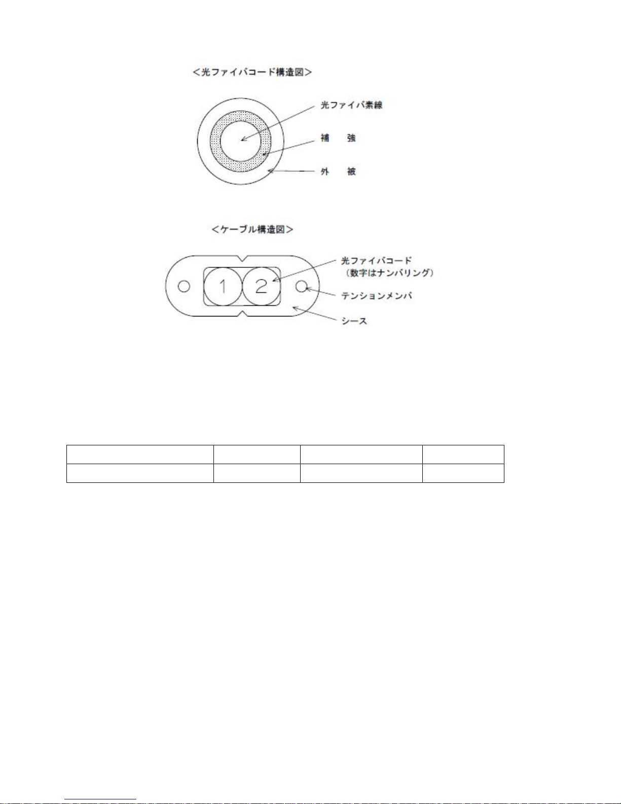
- 17 -
*Identification of optical fiber cord shall be made by sequential number printed on the jacketing
(numbering).
6.3 Optical Connector
Connector type
Specification
Structure
Polishing
Duplex LC connector plug
IEC 61754-20
PNJHY-0048-61-04B
SPC polishing
6.4 The structure of optical fiber cable with connector plug on both side
Flame retardant SM type optical fiber cable with duplex LC connector plug on both side: Refer to
PNJHG-3200-62-05A
The structure of part relieving the cord bending near connector plug: Refer to PNJHG-3200-62-02B
Optical fiber cord
Strength member
Sheath
Not to scale
Reinforcement
Jacketing
Fiber core
Not to scale
Page 18

- 18 -
7. Optical characteristics
7.1 Optical fiber core wire
Item
Wave length
Characteristics
Conversion
L
Conversion formula
Attenuation
lambda=1.31um
Less than 0.40dB/km
0.2=<L<1
Max. 0.25 x L+0.15 dB
L<0.2
Max. 0.2 dB
Zero
dispersion
wavelength
-
1.300~1.324um
-
-
Zero
dispersion
slope
-
Less than 0.093ps/nm2
km
-
-
L=Cable length (Km)
7.2 Optical connector
Connector
Insertion loss
Return loss
DuplexLC
Max. 0.5dB
Min. 40dB
*Cable with connector add connection loss of connector to transmission loss of cable
8. Mechanical characteristics
8.1 Optical fiber cord
Item
Characteristics
Permissible tensile force
Max. 90N (Max. 9kgf)
Permissible bending radius
Min. 30mm
8.2 Optical fiber cable
Item
Characteristics
Permissible tensile force
Max. 140N (Max. 15kgf)
Permissible bending radius
(Only thickness direction)
Min. 40mm
Page 19

- 19 -
9. Flame retardant characteristics
9.1 Optical fiber cable
Item
Characteristics
Flame retardant test
Approved UL1581 VW-1
10. Package
The cable is winded up in a coil and the connector part should be protected from damage while
transportation
Page 20
- 20 -
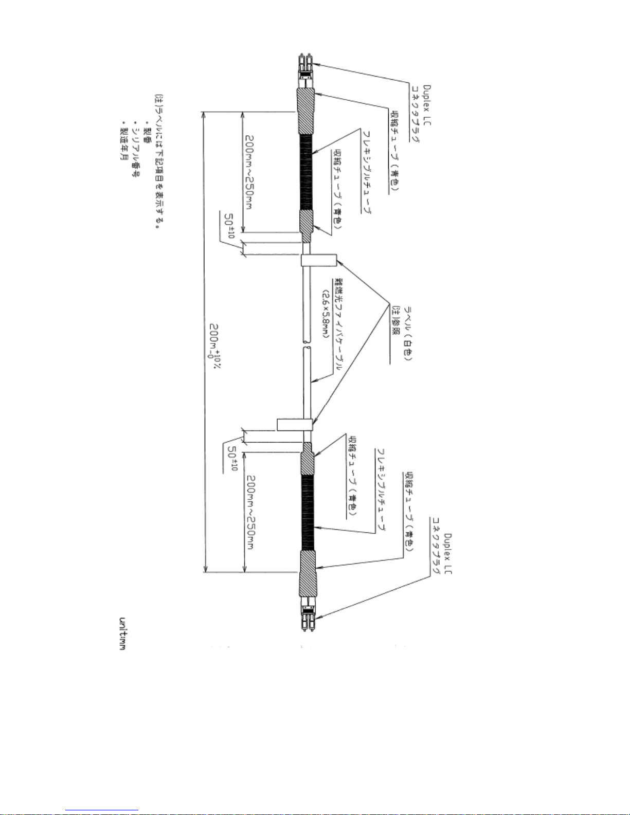
Shrinkage Tube (blue)
Flexible Tube
Shrinkage Tube (blue)
Duplex LC Connector Plug
Label (white)
Refer to the Note
Flame Retardent Fiber Cable
Shrinkage Tube (blue)
Flexible Tube
Shrinkage Tube (blue)
Note: The following items should be on the label
Serial number
Product name
Produced year, month and day
(CCFC-S200)
Duplex LC Connector Plug
Nonflammable optical fiber cable with
duplex LC connector plugs on both sides
Page 21
- 21 -
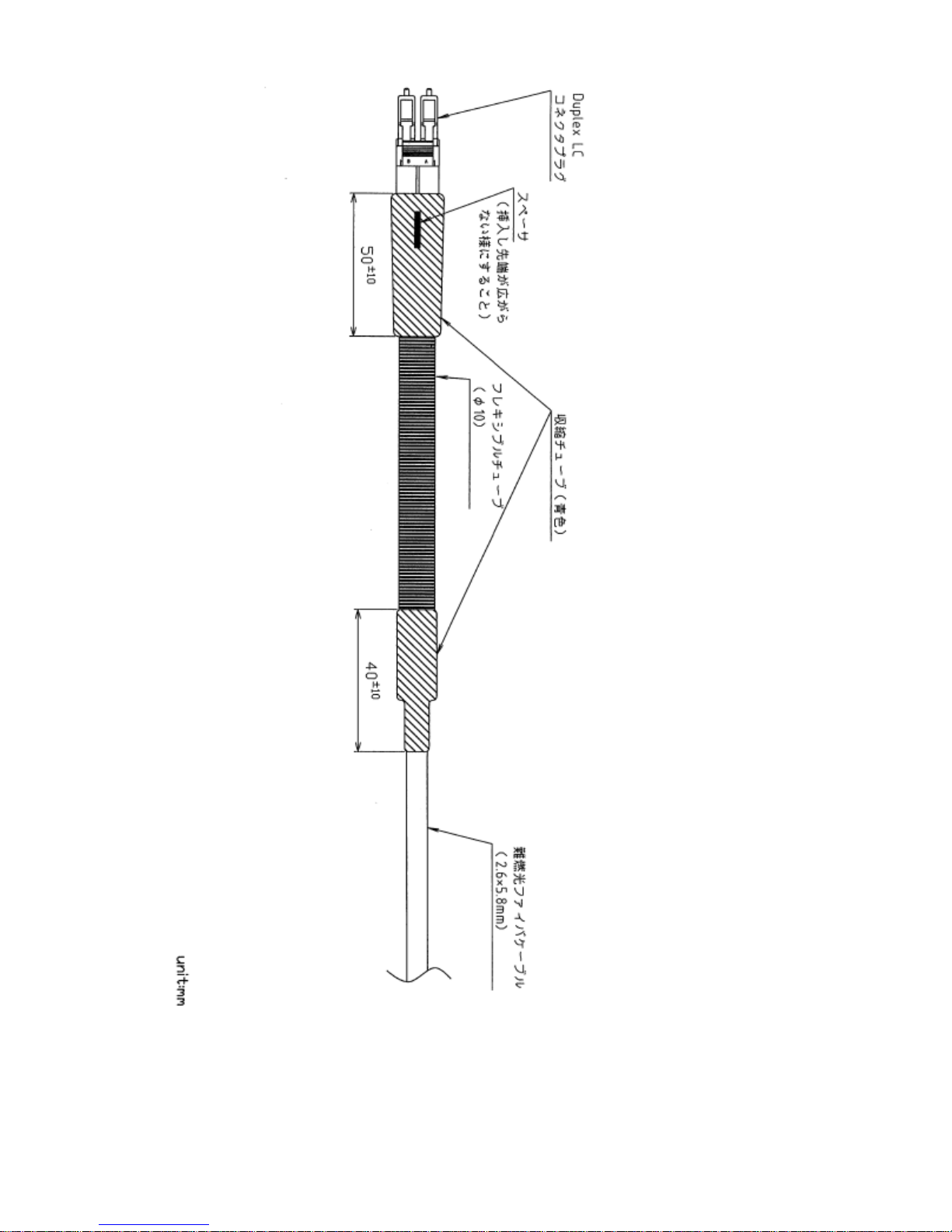
Duplex LC Connector Plug
Spacer (should not be spread)
Flexible Tube
Shrinkage Tube (blue)
Flame Retardent Fiber Cable
Nonflammable optical fiber cable with
duplex LC connector plugs on both sides
Page 22
- 22 -
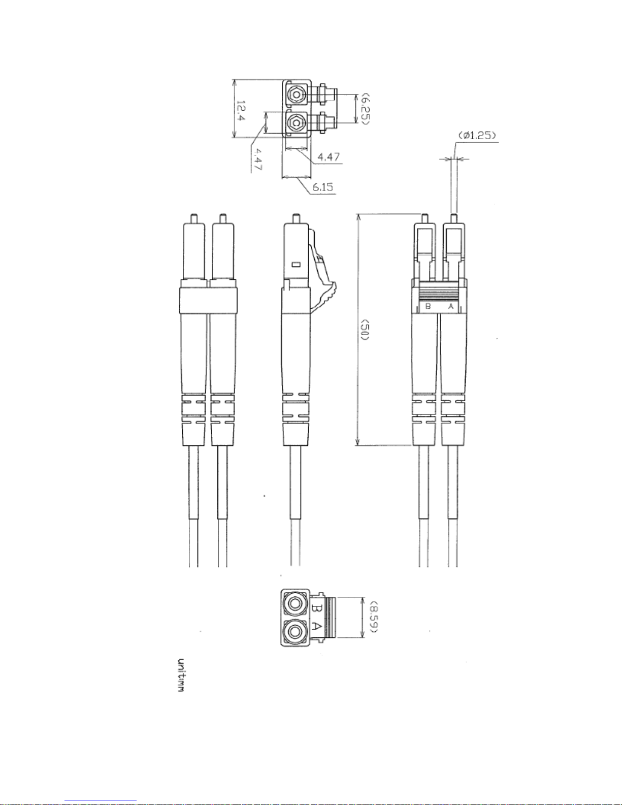
Duplex LC Connector
 Loading...