

Sony Bravia XBR-65X950B, Bravia XBR-65X900B, Bravia XBR-55X900B Operating Instructions Manual

SONY.
Television
T919viseur
Operating
(Setup
Mode
(Guide
Sony
U.S.A.:
http://www.sony.com/tvsupport
Canada:
http://www.sony.ca/support
Instructions
Guide)
d'emploi
d'installation)
Customer
Support
us
FR
BRA
VIA
United
1.800.222.SONY 1.877 .899.SONY
Please Do Not Return
the Product to the
Service
Canada:
http:/ /sup port. sony. ca/fr
Etats-Unis :
http:
Canada
1.877.899.SONY 1.800.222.SONY
Ne retournez pas
States
a
I
/www. sony. com/tvs up port
Canada
Store
Ia
clientele
Etats-Unis
le
produit au magasin
Sony

Owner's Record
The
model
and serial
are
located
the
TV.
the
spaces
to them whenever you call upon
your Sony dealer
TV.
Model
Serial No.
at the side and rear of
Record these
provided
Name
numbers
numbers
below. Refer
regarding
this
CAUTION
To
prevent
exposure,
with an extension cord.
other outlet unless the
fully inserted
•
Operate
AC
• Some
discomfort
fatigue, or nausea) while
3D
stereoscopic
recommends
regular breaks while
video
stereoscopic
and
will vary from person to person. You
must
experience
should stop
images
games
consult a doctor
necessary. You should also review
(i) the instruction manual of any
other
this television and (ii) our website
(http://www.sony.com/tvsupport)
the latest information. The vision of
young
under
development.
(such as a pediatrician or eye
doctor)
children to
or play
Adults should supervise
children to ensure they follow the
recommendations
• Do not use, store. or leave the
Glasses or battery near a fire, or
places
e.g.,
heated cars.
electric
do
the
(U.S.A/Canada
people
video
images
images
frequency
decide
or playing
until the
device
children (especially those
six years old)
before allowing
stereoscopic
with a high temperature,
in
direct
shock
and
not use this AC
receptacle
blades
TV
only on 110-240 V
120 V AC)
may
experience
(such as eye strain,
or playing
3D games. Sony
that all viewers take
watching
or playing
3D games. The length
of
necessary
what works best.
any discomfort, you
watching
or
Consult your
watch
sunlight. or
the
stereoscopic
discomfort
if
you believe
media
used with
is
still
young
3D
video
3D games.
listed above.
blade
plug
can be
watching
breaks
30
video
ends;
under
doctor
images
young
in
sun-
3D
If
in
you
3D
30
us1ng
• When
function, please note that the
displayed
the original
done
the s1mulated
image
is
due
to the conversion
by this television.
Licensing Information
The terms HDMI and HDMI High-
Definition Multimedia Interface.
the HDMI Logo are trademarks or
registered trademarks of HDMI
in
Licens1ng LLC
and other countries.
Fergason Patent Properties, LLC:
US
Patent No 5.717.422
U.S. Patent No. 6.816.141
Manufactured
Dolby
Laboratories.
double-D
or
Dolby
"BRAVIA" and
Motionflow, BRA VIA Sync, and
trademarks
Sony Corporation.
DLNA®, the DLNA Logo and
CERTIFIED(") are trademarks. serv1ce
marks. or certification marks of the
Dig1tal Living Network Alliance.
TrackiD
trademark
Communications
Gracenote,
Gracenote
Explore.
Gracenote
the "Powered
either registered trademarks or
trademarks
United States
Operac~!
Software ASA.
Opera
for
reserved.
Wi-Fi, Wi-Fi Direct and Miracast are
trademarks
of Wi-Fi Alliance.
"Sony Entertainment Network logo"
and "Sony Entertainment Network"
are
MHL. Mob1le High-Definition Link
the
registered trademarks of
Licensing. LLC
For DTS patents, see
in
http
under
Lim1ted. DTS. the Symbol,
the Symbo! together are reg1stered
trademarks. and DTS Digital
Surround
© DTS, Inc. All Rights Reserved.
symbol are trademarks of
Laboratories
is a trademark
Gracenote
Devices SDK from
Software ASA. All rights
trademarks
MHL
Logo are trademarks or
//patents.
license from DTS Licensing
the United States
under
Dolby
BRAVIA,
or registered marks of
of Sony Mobile
AB.
Gracenote
VideoiD.
logo and logotype, and
of
or registered
is a trademark
Gracenote
MusiciD, the
by
Gracenote"
Gracenote
and/or
Copyright
of Sony Corporation.
dts .com.
30
modified
license from
other countries.
from
and
and
the
S-Force,
l!iJ
are
DLNA
or registered
eyeO.
Video
logo
are
in
the
Opera
1995-2014
trademarks
and
MHL
Manufactured
& DTS and
of DTS. Inc.
Designed
Under
Electronics Inc.
2013
The Bluetooth® word mark and logos
are
and any use of such marks
Corporation
trademarks
those of their respective owners.
The N Mark
registered
Inc.
countries.
HIGH-DEFINITION
with UEI
License from Universal
owned
by
trademark
in
the United States and
TELEVISION
Technology™
Portions©
the Bluetooth SIG, Inc.
is
under
license. Other
and
trade
names
is a trademark
of NFC Forum,
UEI
by
or
2000-
Sony
are
in
other
Hi:lrniTM
HIGH
DEFINITION
MULTIMEDIA
INTERFACE
0 gracenote.
O
OPERA
software
'M
~MHL
Mobile
High-i:Jefinition
~d-~
Digital
Surround
Link
The 55
viewable
class has a 64.5 inch
image size (measured
class
has a 54.6 inch
image size and the 65
Location of the
identification label
Labels for the Model
..
Supply
applicable safety
Manufacturing date are located
the rear of the
(b
•
•
•
rating (in
The
illustrations
control used
the
RMF-YD003
Control)
(infrared) Remote
otherwise stated.
The
illustrations
may differ depending
model.
Retain this
reference.
accordance
regulation)
TV
.
of the remote
in
this
(Touchpad Remote
and RM-YD102
used
manual for future
viewable
diagonally).
No
.,
Power
with
and
on
manual are of
(IR
Control) unless
in
this manual
on
your
TV
0
Bluetooth®
Experience
The BRA VIA® 4K
Thank you for choosing Sony!
opens the door to the
TV
VIA®
BRA
Experience". This
get the most out of your
Please
at:
U.S.A.:
Canada: http://www.sony.ca/registration
Four
Set, Source, Sound,
1
Now that you have made the best
in
to remove
packaging
2
To experience the stunning detail
BRA VIA
High-Definition programming.
•
take a moment
http://productregistration.sony.com
Steps
to a 4K TV Experience
Set
backlit LCD
LED
all accessory contents from the
before setting up your
Source
you need
TV,
signal
Upgrade
high-definition (4K) by contacting your
HD service provider.
your
TV
Your
document
to register your
and
technology,
TV
will help
TV.
Setup.
access
or content source to
to
new
TV
"4K
you
TV
selection
be sure
TV.
of your
Bring the astonishing resolution
•
life with Sony 4K
to
TV
HD
Sony 4K
Ultra
depends
Receive over-the-air HD broadcasts with
•
an
directly
Visit
more information on antenna
and setup.
Discover the
•
available
Blu-ray
equipment.
Sound
3
Complete
with a
system or A/V receiver from
Setup
4
Install
page
See
diagrams. To
quality
HDMI
Interface) cables.
Ultra
Media
HD
on region)
HD-quality
to the
http://www.antennaweb.org
on super-high resolution
Disc
the high-definition experience
BRA VIA
TV
your
14 for
for your 4K experience, use Sony
(High-Definition Multimedia
Player.
antenna connected
back
wealth
player
TM
Sync™
connect
and
sample
assure the highest
help
(The
of your
of entertainment now
and other
surround sound
connection
of your
availability
TV.
for
selection
Sony
Sony.
your sources.
HD
learn
To
U.S.A.:
Canada: http://www.sony.ca/hdtv
108
30
0/2
p
3,840
4p
a resolution of
in
1
4K*
t/t/t/t/t/t/
TV
signals
inputs.
displays all
TV
This
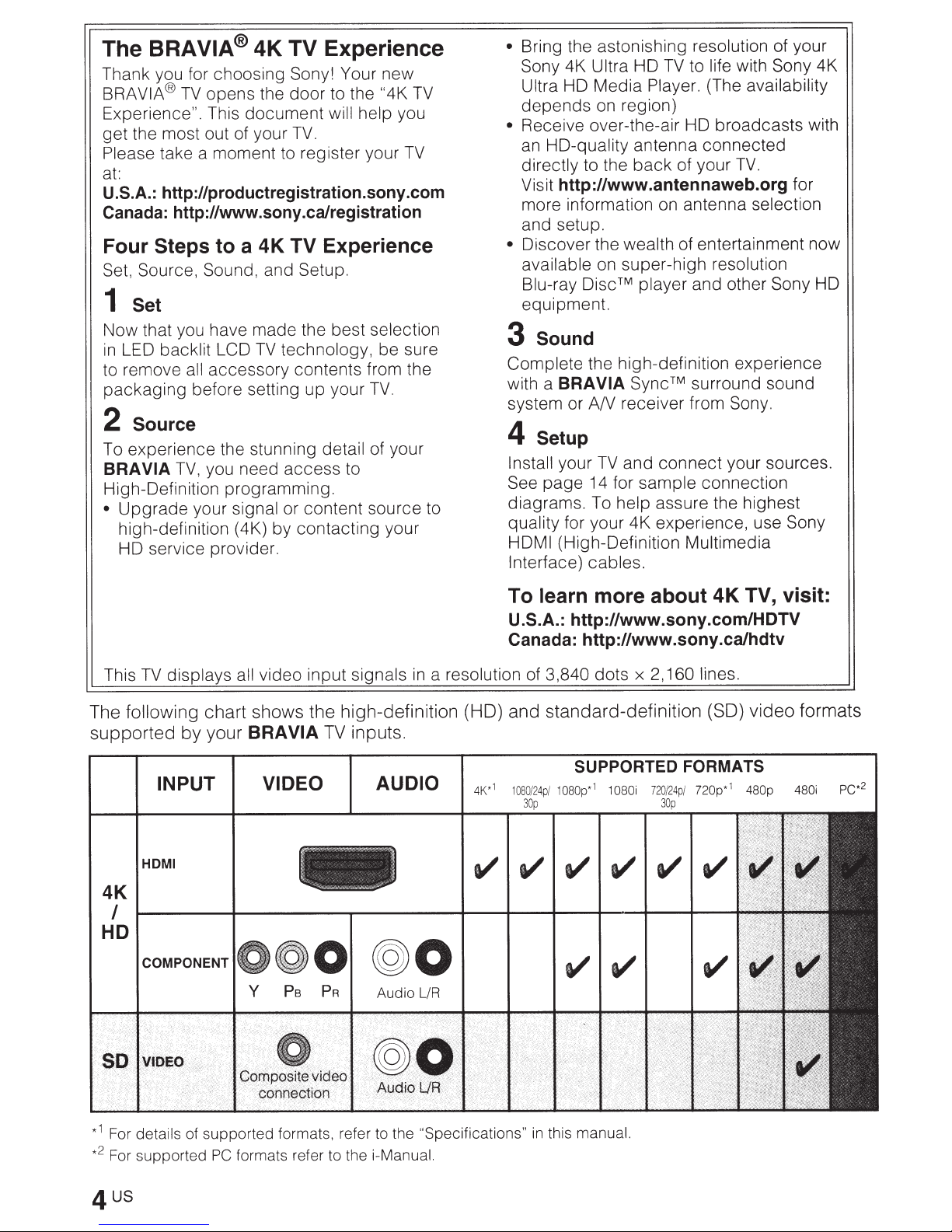
following chart shows the high-definition (HD) and standard-definition (SO) video formats
The
your
supported
by
INPUT
I
HOM
video input
VIA
BRA
VIDEO AUDIO
more about 4K TV, visit:
http://www.sony.com/HDTV
2,160 lines.
x
dots
SUPPORTED FORMATS
/ 1
080p
1
080i
1
*
72
0/
30
24p
p
/ 720p*
1
480p
4K
I
HD
0
@0
t/t/
480i
PC*
2
1
For details of supported formats, refer to the
*
2
For supported
*
formats refer to the i-Manual.
PC
"Specifications"
in
this
manual.

5
us
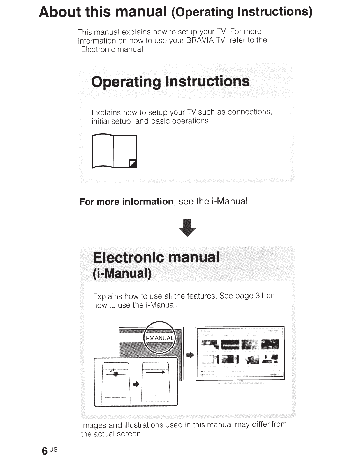
About this
manual explains
This
information on how to use your BRA
"Electronic manual".
manual
how to setup your
(Operating Instructions)
For more
TV.
refer to the
TV,
VIA
Operating
Explains
initial
how to setup your
setup, and basic operations.
lnstrQCtiPAS
For more information,
such as connections,
TV
see the i-Manual
Explains
how to use the
----~
't
------..
~.
Images
the actual screen.
sus
and
how to use all
i-Manual.
---
-
-------
-------
u-
.....
--
.,.
-~
-
-
-
~
..
L
illustrations
used
the features. See
l
manual
this
in
on
page
may differ from
31
Table
of Contents
Checking
Inserting
Before setting
1:
Attaching
2:
Connecting
3:
Securing
4:
Bundling
5:
Connecting
6:
Running initial
Watching
Using the remote
Discovering the contents you
Enjoying
Selecting
the accessories ........................................................................ 8
batteries into the remote
up
your
the
Table-
the
the
TV
the
cables
the
setup ........................................................................... 24
TV
...................................... ..................................................... 25
control
social
various contents and
networking
TV
.......................................... :
Top
Stand
TV
.............................................................................. 14
..................................................................................
........................................................................... 22
TV
to the
Internet ....................................................... 23
........................................................................ 26
while
control
.......................................................... 1 0
like
(Discover) ......................................... 28
watching
tools
................................................ 8
.............................. 9
TV
(Social Viewing) ............ 28
(Home Menu) .............................. 29
l!iJ
20
Looking for instructions
electronic manual (i-Manual)
Troubleshooting ...................................................................................... 34
How
Specifications ......................................................................................... 37
Installing
Installing
Safety Information ..................
to care for your BRA VIA
the
TV
the
TV
TV
............................................................ 36
to the Wall ..... .........
against a
wall
or
..
....................
enclosed
in
the
~
...
G
..
..............................
area ...................................
..
.................... ..................... 42
..
.................... 39
41
Checking the
Inserting batteries
accessories
)*
Remote
IR
Touch
AAA
Size
power
AC
(XBR-65X950B
Cable
Cable
(XBR-65X950B
Table-
Fixing
X
(MS
Wall-Mount
(XBR-65/55X900B
Wall-Mount
(XBR-65/55X900B
Active
Blaster
IR
Camera
(XBR-65/55X900B
Operating
Control
Remote
pad
batteries
cord
clamper
holder
Top
screws
16) (4)
30
(1)
Stand
Attachment
Attachment
Glasses
(1)
cover
Instructions
(1
Control
4)
(
(1)
only)
(3)
only)
(2)
Table-Top
for
only)
only)
(battery
(1)
only)
(this
)*
(1
Stand
(long)
(M6)
(short)
(MS)
included)
manual)
(2)
(2)
(2)
and
into
the remote
control
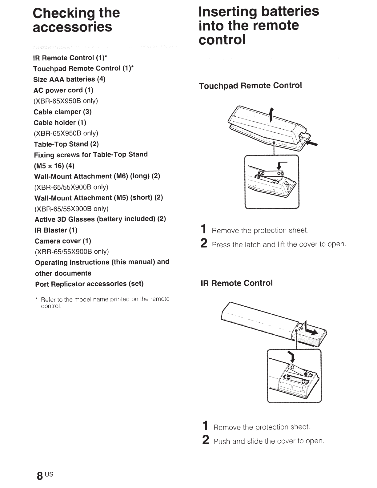
Touchpad Remote Control
Remove the protection sheet.
1
the cover to open.
2
Press
latch and
the
lift
other
Port
*
documents
Replicator
Refer to the
control.
accessories
model
name printed on the remote
(set)
Remote Control
IR
Remove the protection sheet.
1
slide the cover to open.
2
Push
and
sus
•
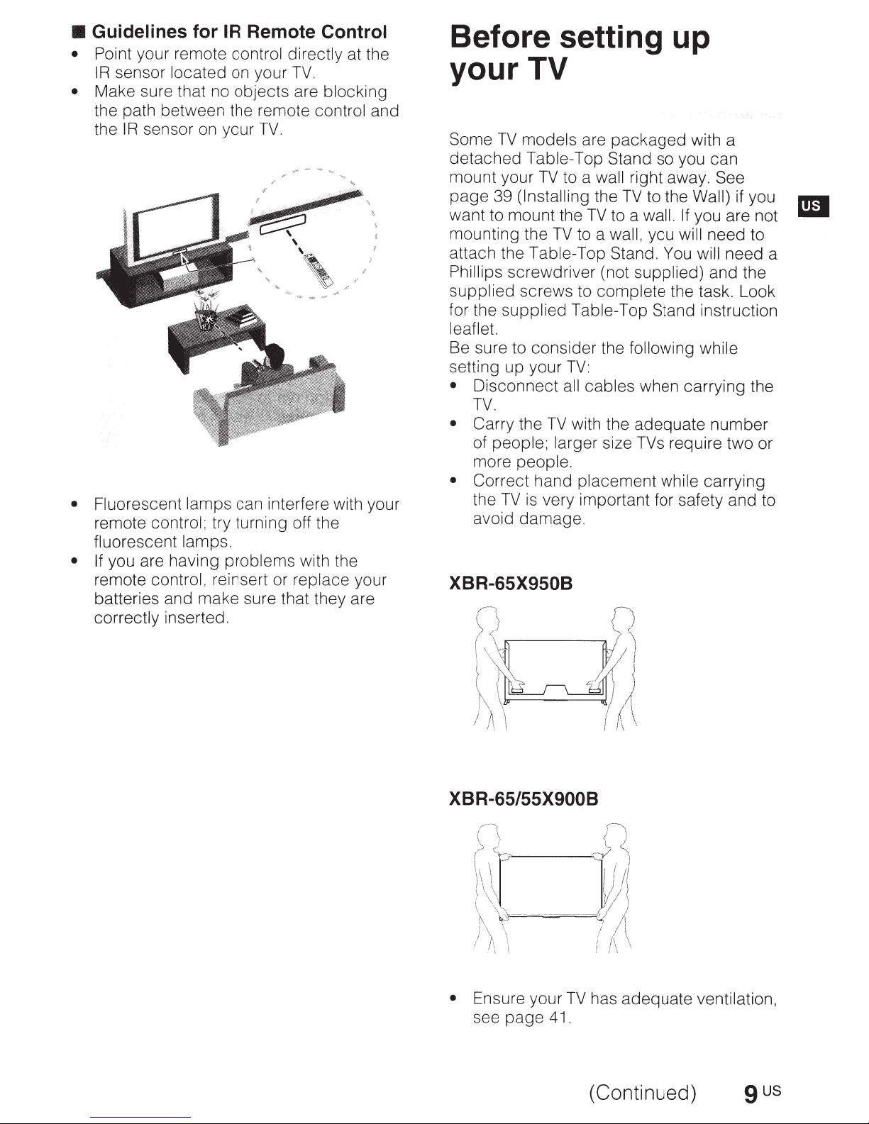
Guidelines for
• Point your remote control directly at the
IR
sensor located on your
•
Make sure that no objects are blocking
the path between the remote control and
the
IR
sensor on your
•
Fluorescent lamps can interfere with your
remote control; try turning off the
fluorescent lamps.
•
If
you are having problems with the
remote control, reinsert or replace your
batteries and make sure that they are
correctly inserted.
IR
Remote
TV.
[
~
Control
TV.
'
,,
Before setting up
your TV
Some
detached
mount your
page
want to mount the
mounting the
attach the Table-Top Stand.
Phillips
supplied screws to complete the task. Look
for the supplied Table-Top Stand instruction
leaflet.
Be sure to consider the
setting up your
•
• Carry
• Correct
TV
models are
Table-Top Stand so you can
TV
to a
39
(Installing
TV
screwdriver (not supplied) and the
TV:
Disconnect
TV.
the
of people; larger size TVs require two or
more people.
the
TV
avoid damage.
all
TV
hand placement while carrying
is
very important for safety and to
packaged
wall
right away. See
the
TV
to the
TV
to a wall.
to a
wall,
you
following
cables when carrying the
with the adequate number
with a
Wall)
If
you are not
will
need to
You
will
while
if you
need a
XBR-65/55X900B
• Ensure your
see
page
TV
41.
(Continued)
has adequate ventilation,
9
us
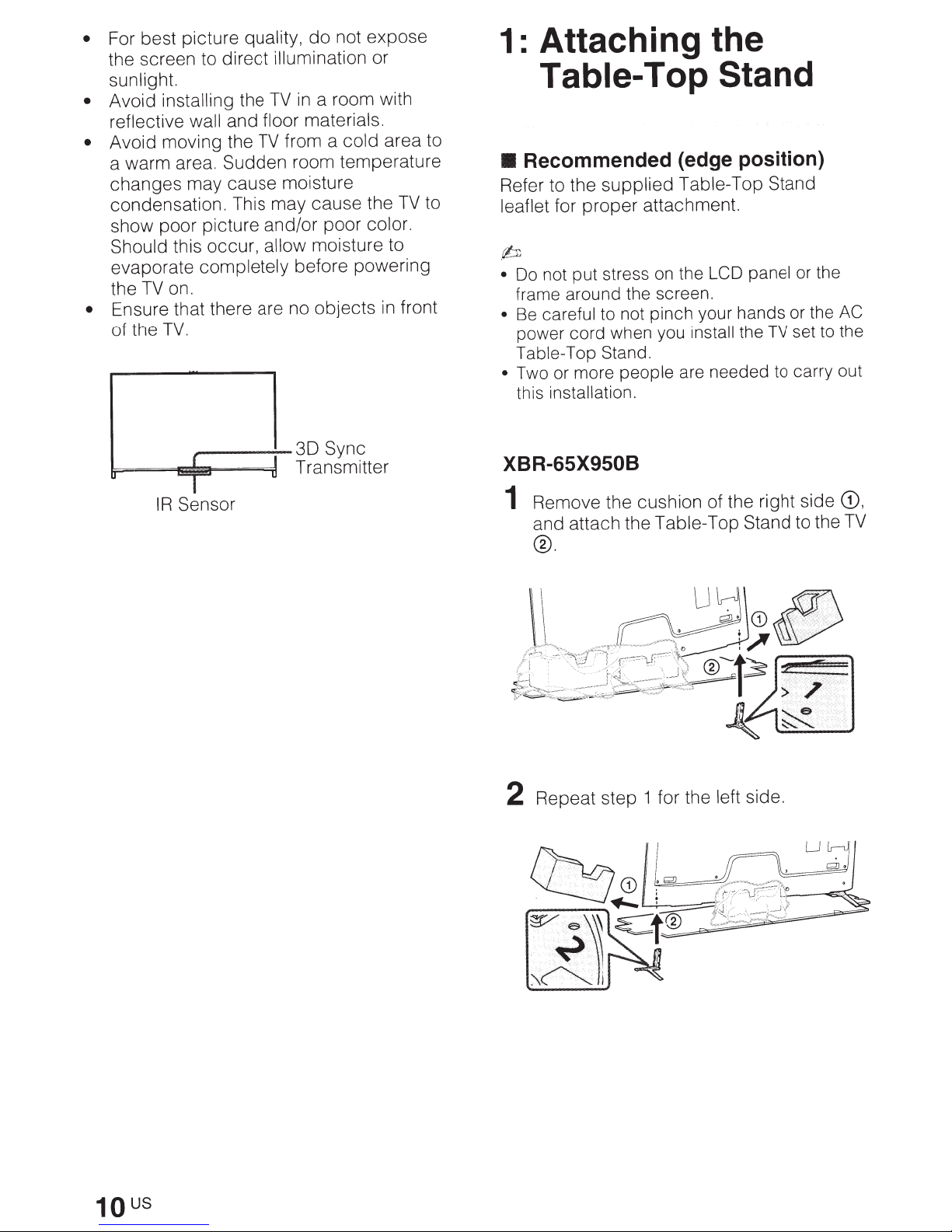
not expose
For best picture
•
the screen to direct
sunlight.
• Avoid
reflective
Avoid moving the
•
a warm area. Sudden room temperature
changes may cause moisture
condensation. This may cause the
show poor picture and/or poor color.
Should
evaporate completely
the
Ensure that there are no objects
•
of the
installing the
wall
this occur,
on.
TV
TV.
,......--~
quality,
and
TV
~=-=-~=1~==~l
do
illumination
a room with
in
TV
materials.
floor
from a
allow
before powering
30
Transmitter
cold
moisture to
Sync
or
in
T
Sensor
IR
area to
to
TV
front
1: Attaching the
Table-
Recommended (edge position)
•
Refer to the
leaflet
for proper attachment.
Top
supplied Table-Top
.b
Do not put stress on the
•
frame around the screen.
Be careful to not pinch your hands or the
•
when you
power
Table-Top Stand.
Two or more
•
this
cord
people
installation.
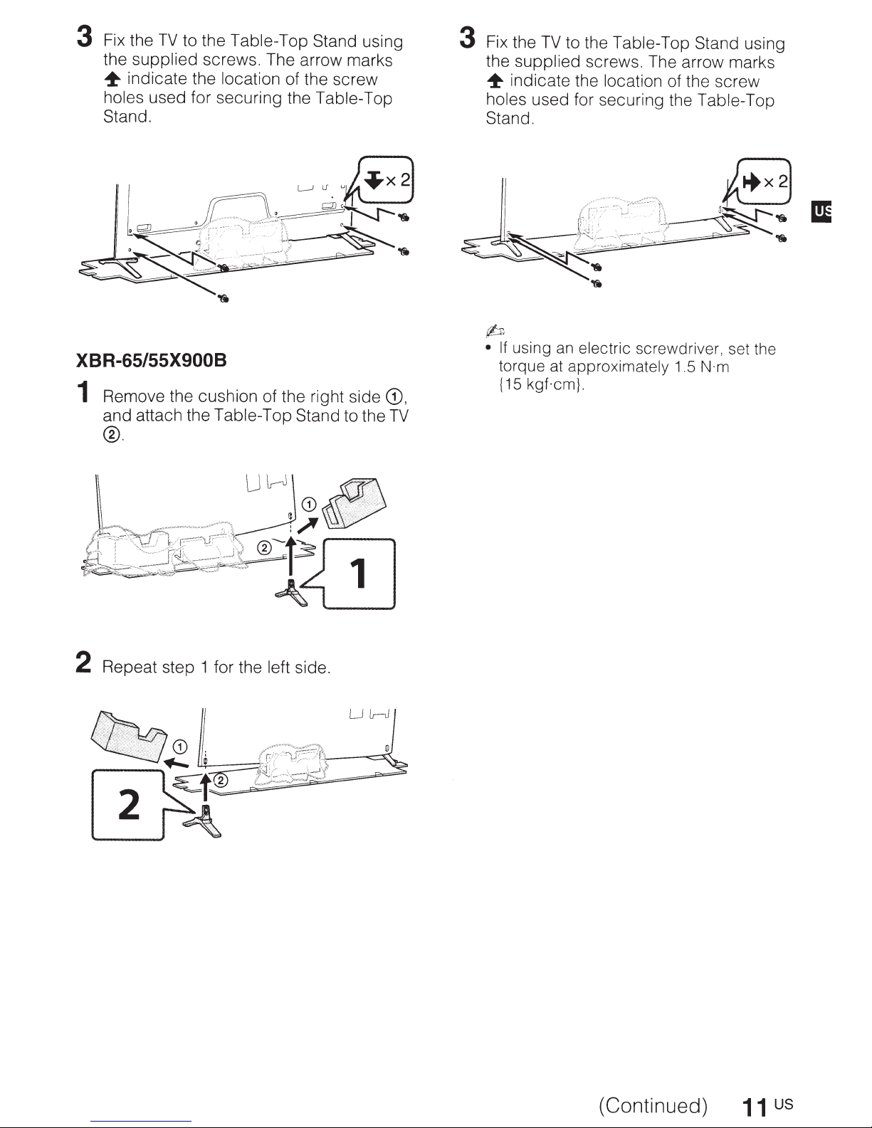
XBR-65X950B
Remove the cushion of the right side
1
and attach the Table-Top Stand to the
®.
Stand
Stand
LCD panel
set to the
install the
are needed to carry out
TV
or the
AC
CD,
TV
us
10
Repeat step 1 for the
2
left
side.
3
Fix the
the
~
holes
Stand.
TV
to the Table-Top Stand
supplied
indicate the
used for securing the
screws. The arrow marks
location of the screw
Table-Top
XBR-65/55X900B
1
Remove the cushion of the right side
and attach the Table-Top Stand to the
®.
using
CD,
TV
3
Fix the
the
~
holes
Stand.
(bJ
•
TV
to the
supplied screws. The arrow marks
indicate the location
used for securing the Table-Top
If
using an
torque
{15
at
approximately
kgf.cm}.
Table-Top Stand
electric
screwdriver, set the
of the screw
1.5
N·m
using
2
Repeat step 1 for the left
side.
(Continued)
11
us
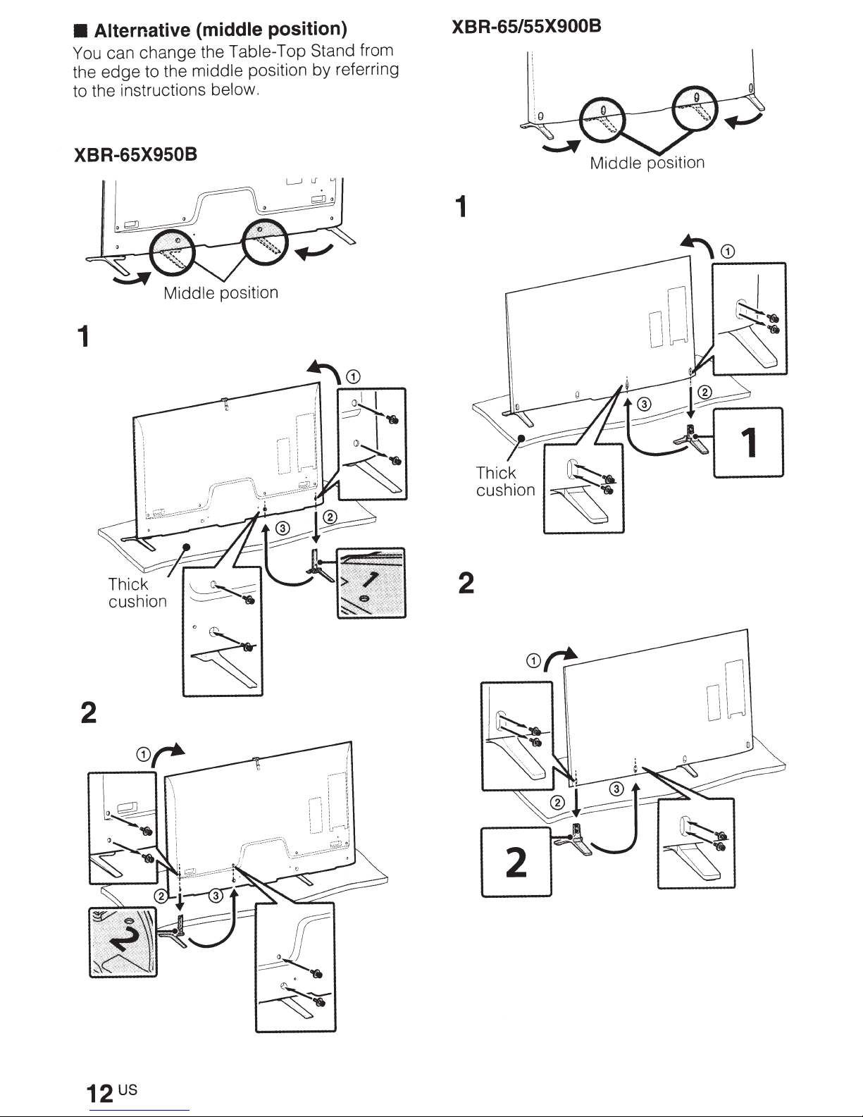
Alternative (middl
~
can change
thou
edge
e
to the
instrhttps://manualmachine.com/
t h e
th
middle
Ions below. Y
XBR-65/55X900B
e position)
T
able-To
positio~
s
btand from
referring
XBR-65X9508
1
1
Middle
position
2
2
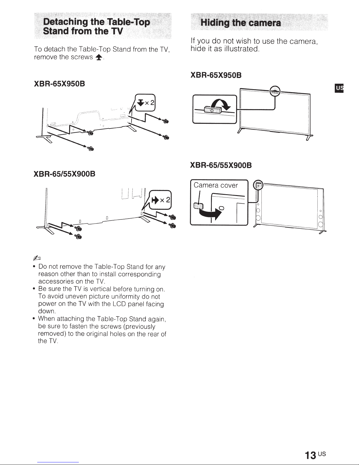
To
detach
remove the
the
Table
screws
XBR-65X950B
XBR-65/55X900B
T
+
op
Stand from the
TV,
If.
you
do
not
wish
hide it as illustratedo
t
XBR-65X950B
XBR-65/55X900B
use the camera,
~
•
Do
not
reason other than to
•
accessories
Be
To
power
down. e
•
When
be sure to fasten
removed)
the
remove
sure
the
avoid uneven
on
attaching
TV.
the
Table
on
the
TV
is v
p~t~~:l
the
TV
with
the
th
to
the o . e screws
nglnal holes
inst~J
TV.
t'
Tabl
op Stand for any
corresponding
be;ore turning
th
~~Dormlty
panel facing
e-Top Stand again
(previously
on
the rear of
do
on.
not
,
Camera
cover
J~
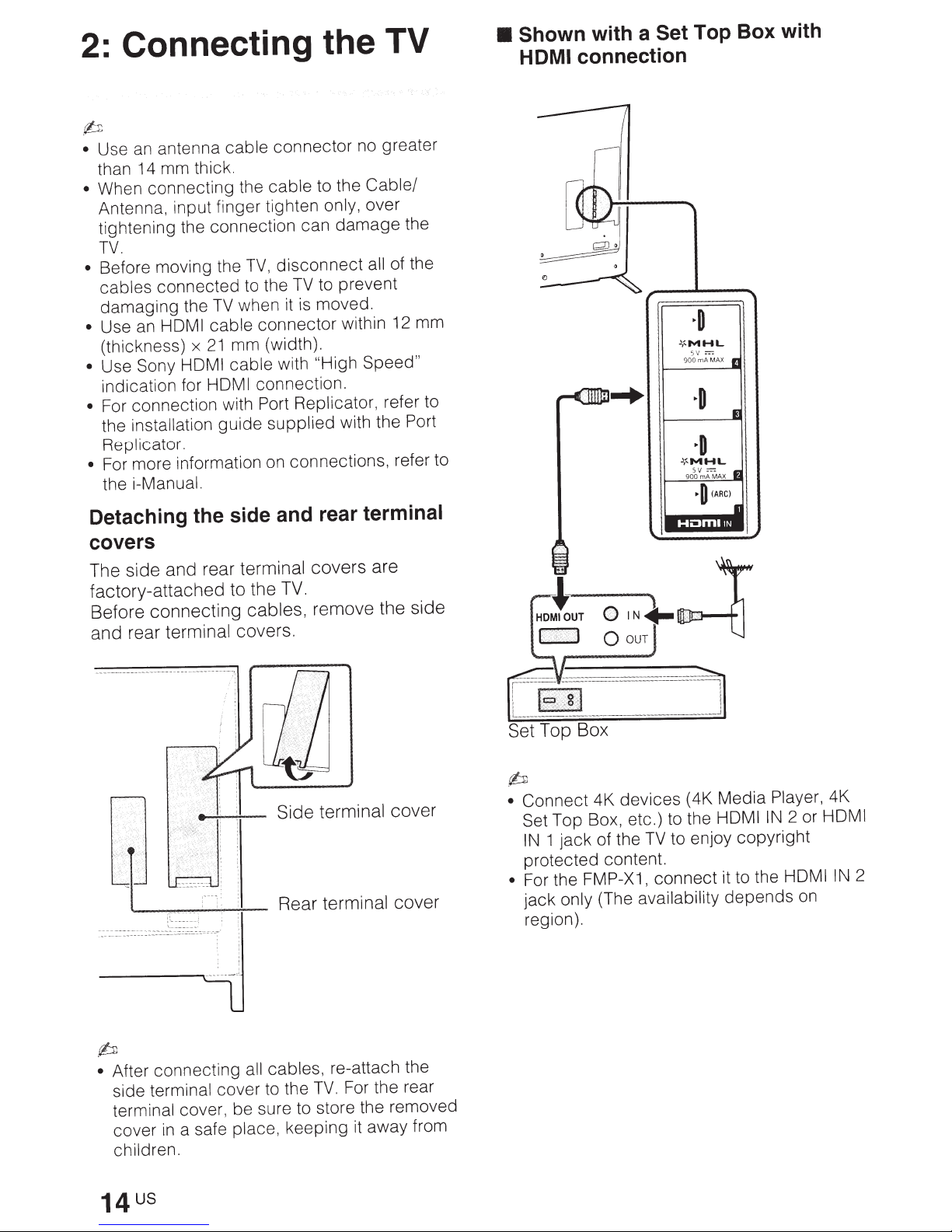
Connecting the TV
2:
p
antenna
an
Use
•
than 14 mm thick.
When connecting the
•
Antenna, input finger tighten
tightening the connection can
TV.
Before moving the
•
cables
damaging
Use
•
(thickness)
Use Sony
•
indication for
• For connection with Port
the installation
Replicator.
For more information on connections, refer to
•
the
connected
HOM
an
i-Manual.
cable
TV
the
I cable
21
x
HDMI cable
HDMI
guide
connector
cable
disconnect
TV,
to the
when it
mm (width).
TV
is
connector
with
connection.
Replicator,
supplied
no greater
to the
to prevent
moved.
"High Speed"
Cable/
only, over
damage
of the
all
within 12 mm
refer to
with the Port
the
• Shown
HDMI
connection
with a
Set Top Box with
~MHL
Detaching the side and rear terminal
covers
The side and rear
factory-attached to the
Before connecting
and rear
terminal covers.
terminal covers are
TV.
cables,
remove the side
terminal
Rear
cover
()IN~
0
)~
OUT
p
devices
Connect
•
Set
1
IN
protected content.
• For the FMP-X1,
jack
region).
4K
Top Box, etc.) to the HOM
jack
only
of the
(The
TV
connect
availability
•,
"
•
";_
;
·
(4K Media
to enjoy
it to the HOM
depends
Player, 4K
2 or HOM
IN
I
copyright
on
I
2
IN
I
p
After connecting all cables, re-attach the
•
side terminal
terminal cover, be sure to store the removed
cover
children.
in
cover to the
a safe
place,
TV.
keeping it away from
For the rear
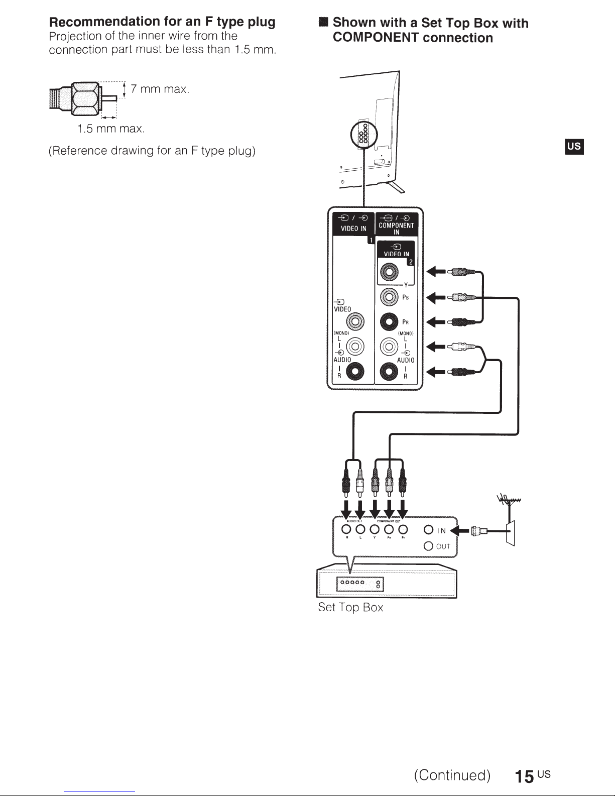
Recommendation for an F type plug
Projection of the inner wire from the
connection part must be
less
than 1.5 mm.
• Shown
COMPONENT
with a
Set
Top Box with
connection
~]7mmmax
.-.---.
1.5 mm max.
(Reference drawing for
an
.
F type
plug)
VIDEO
OPR
(MONO)
1©J
TO
©J1
oAr
(MONO)
..
+-
..
..
..
Set Top Box
(Continued)
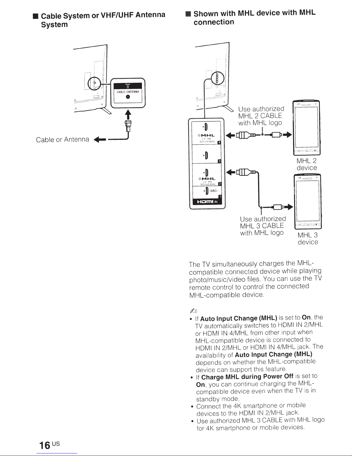
• Cable System
System
or VHF/UHF Antenna
• Shown
connection
with MHL device with MHL
G=:;:;
•
Use authorized
MHL 2
with MHL logo
CABLE
Cable or Antenna
~:-MHL
:-:-:
sv
rnA MAX
900
+QI[)m-!-C]l+
--'"-
-
-- ..
:-o-
r-
MHL2
device
•0=
0
T--<=P+
Use authorized
MHL 3
CABLE
with MHL logo MHL
simultaneously charges the MHL-
TV
The
compatible connected device while playing
photo/music/video files. You can use the
remote control to control the connected
MHL-compatible device.
"_._
3
device
TV
rb
set to
Change (MHL)
Input
Auto
• If
automatically switches to
TV
4/MHL from other input when
or HDMI
MHL-compatible
HOM I
availability of
depends
device
Charge MHL during Power
• If
On,
compatible
standby
• Connect
devices
Use authorized MHL 3
•
IN
device
2/MHL or HDMI
IN
Auto Input
on whether the MHL-compatible
can
support
this feature.
you can continue charging the MHL-
device
even when the
mode.
the 4K smartphone or mobile
to the HOM I
IN
for 4K smartphone or mobile devices.
is
HOM I
connected to
is
4/MHL jack. The
IN
Change (MHL)
Off
2/MHL jack.
CABLE with MHL logo
IN
is
TV
On,
set to
the
2/MHL
in
is
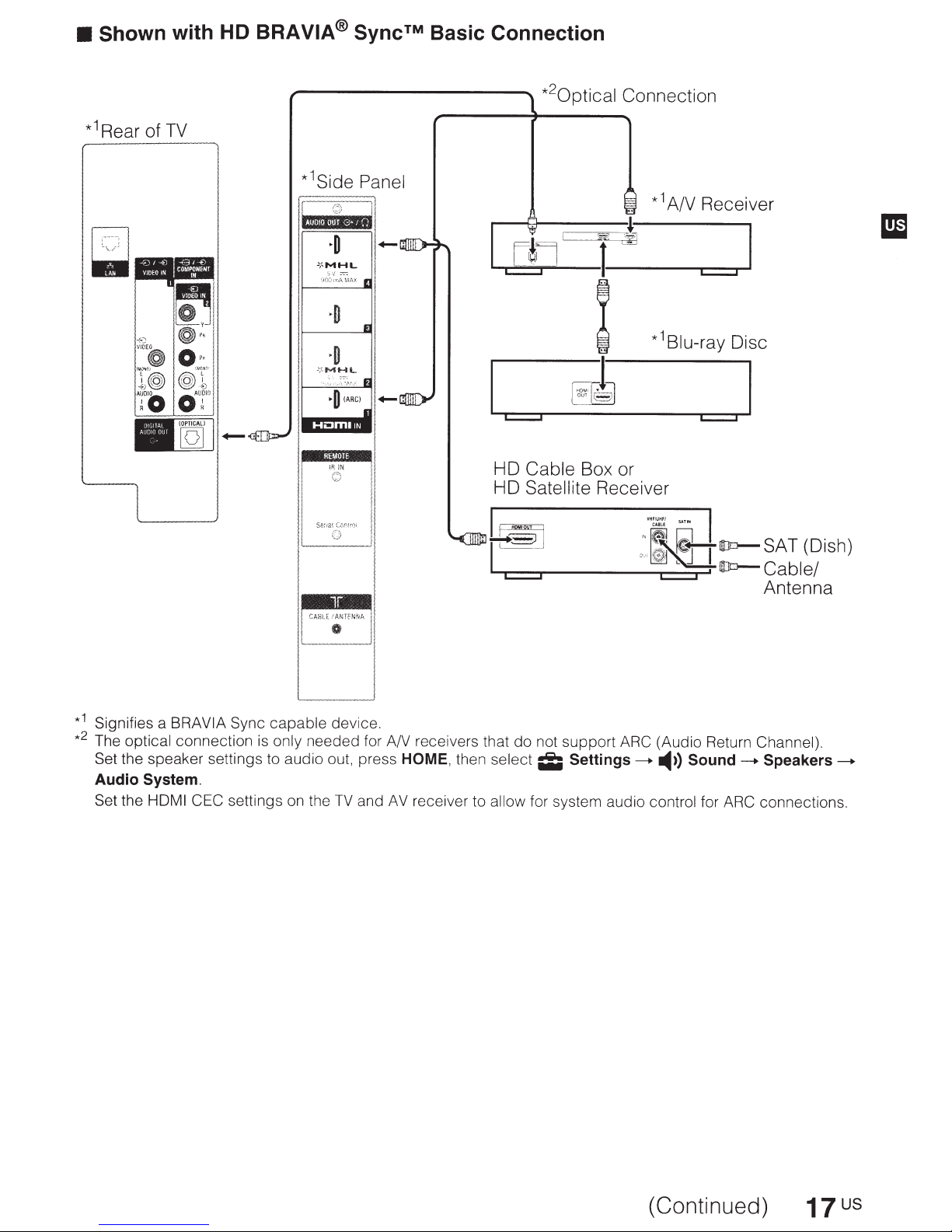
•
Shown with HD BRA
VIA® Sync™
Basic Connection
1
*
Rear of
TV
,------------....
2
*
0ptical
c::::::J c::::::J
HD
Cable
HD
Satellite
Connection
Box or
Receiver
1
*
A/V Receiver
1
*
Blu-ray
Disc
__
CABLE
-~TfNNA
L
____
1
*
Signifies a BRA
2
*
The optical connection
Set the speaker settings to audio out, press
Audio System.
Set the HOM
VIA
Sync
capable
is
only needed for A/V receivers that
I CEC settings on the
device.
TV
I
,
II
JI
and
HOME,
AV
then select
receiver to allow
.Lii~
...__
l
...-c:::::::J----.~---
do
not support
ii;
Settings____..
for system audio control for
.'
t~ID=>-
0
"
-
'
~
.....
~-1.:
ARC (Audio Return Channel).
-4))
·
·
:.
SAT(Dish)
_,j
~!
ID=>-
Cable/
Antenna
Sound
____..
Speakers____..
ARC
connections.
(Continued)
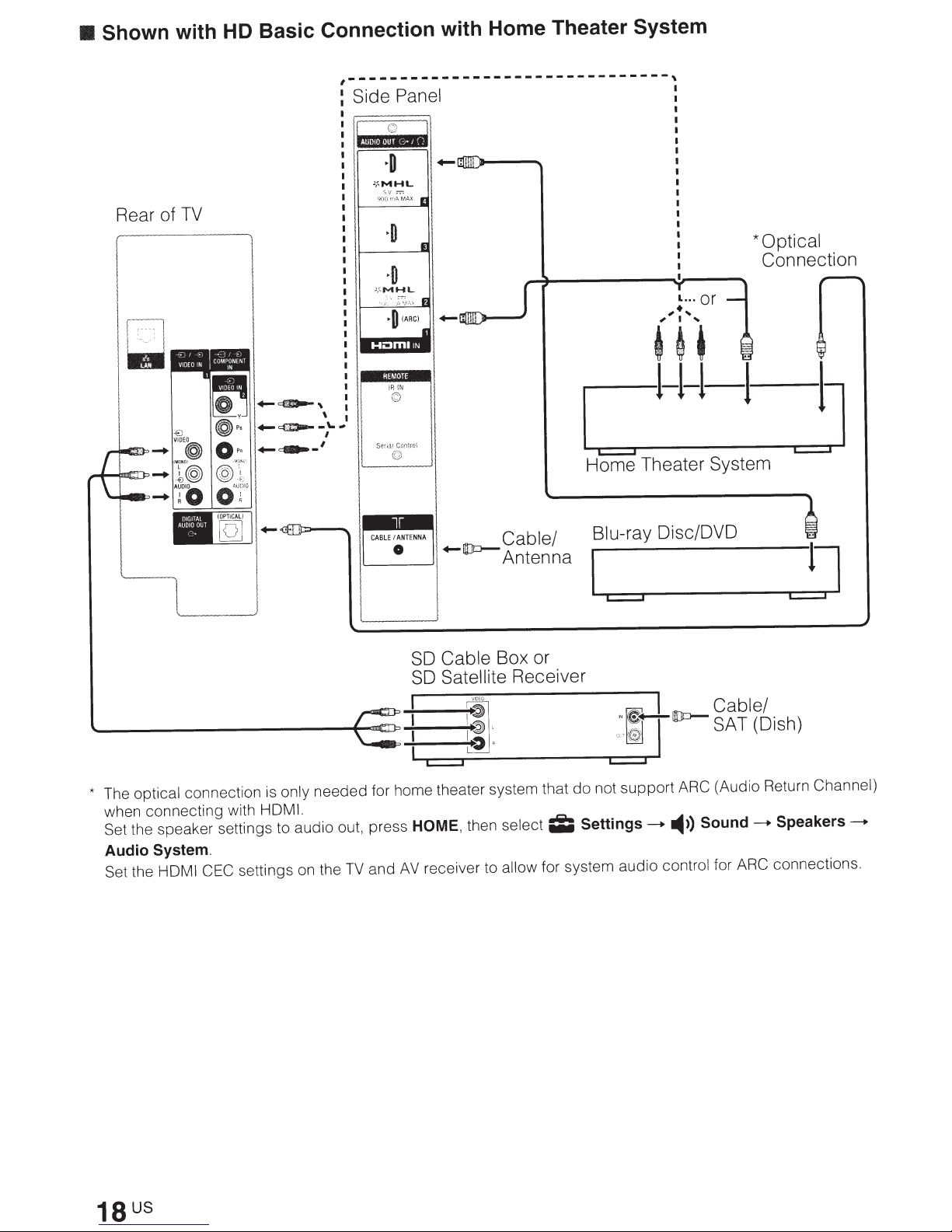
Shown with HD Basic Connection with Home Theater System
•
,-------------------------------,
Side Panel
.. ,·
l
I
TV
Rear of
i~
I :
...
.,_~,
.,_~-\.-
.,_~-'
\ I
/
+-(lo-
Cable Box or
SO
Satellite
SO
Cable/
Antenna
Receiver
*Optical
Connection
c::=:::J
Home Theater System
Blu-ray Oisc/OVO
only needed for home theater system that
The optical connection
*
when connecting with
Set the speaker settings to audio out, press
Audio System.
Set the HOM I CEC
is
HDMI.
settings on the
TV
~
IDEO
1:
1
--c::=:::J----------------~c::=:::J----
HOME,
AV
and
; V
not support
do
Settings-.
then select
receiver to allow for system audio control for
;I;
I
"~~UDo-
'
I
~
~,
ARC (Audio Return Channel)
Sound
-4))
bl
c
a e .
SAT
ARC
I
(D1sh)
Speakers
-.
connections .
-.
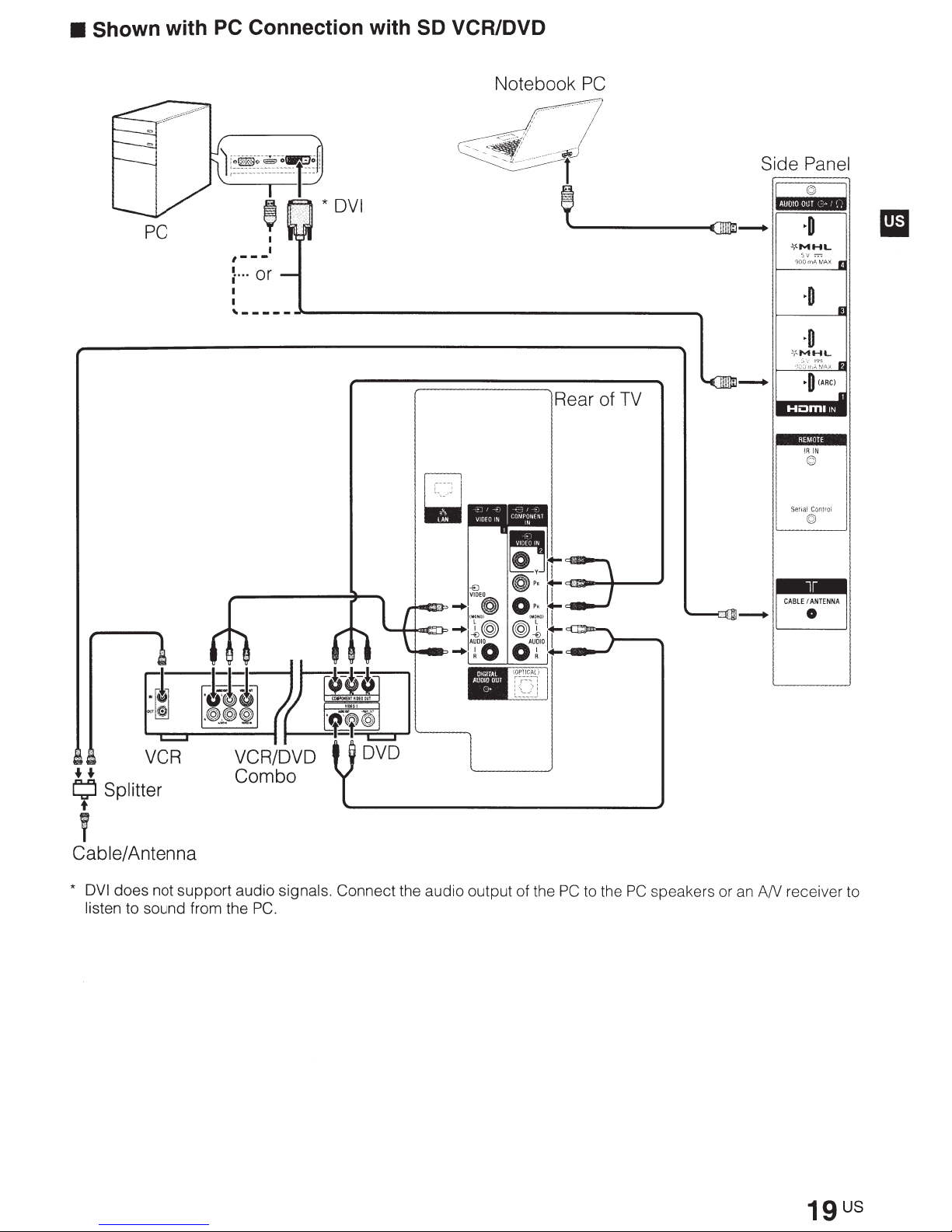
• Shown with
PC
Connection with SD VCR/DVD
PC
Notebook
~~·~
....
~~~·""·T·~
' *
I
I
,---
~
...
or
'-----~--------------------------------~
DVI
PC
·········~;
Side Panel
f
1
~·1
HI·I·I~---
''---~
--(]9j---.
Rear of
TV
~o
.lf.MHL
sv =
900
mA
MAX
11
~o
I
~o
lf
...
MHL
,,ot\,;~I',X
I
~o
(ARC)
- :
I
I
t-
II
I
IIJal
I
iR
iN
am
......
L;l
Splitter
t
T
Cable/Antenna
*
DVI
does not support audio signals. Connect the audio output of the
VCR
listen to sound from the
PC.
PC
to the
PC
speakers or
I CABLE.TENNA I
D
an
AN receiver to
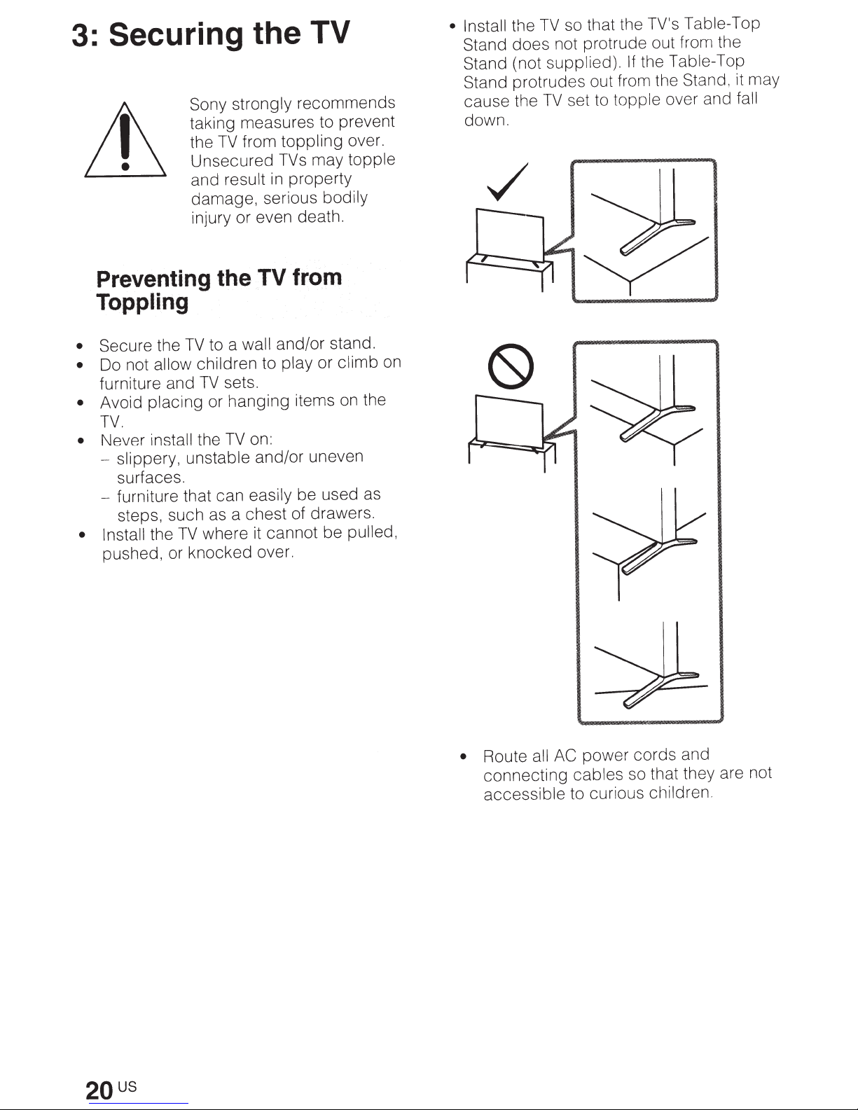
Securing the TV
3:
strongly
Sony
taking measures to prevent
from
TV
the
Unsecured
and result
damage, serious bodily
injury or even death.
Preventing the
in
TV
Toppling
wall
to a
Secure the
•
Do not allow
•
furniture and
Avoid
•
TV.
Never
•
- slippery, unstable
surfaces.
furniture that can
steps, such as a chest of drawers.
• Install
pushed, or knocked over.
TV
placing
install
TV
the
children to
sets.
TV
or hanging items
on:
TV
the
and/or uneven
easily
cannot be pulled,
where
it
recommends
toppling
TVs
property
over.
may topple
from
and/or stand.
or climb
play
the
on
be used as
on
• Install
Stand
Stand (not supplied).
Stand protrudes out from the Stand, it may
cause the
down.
the
does
not protrude out from the
the Table-Top
If
set to topple over and
TV
fall
so that the TV's Table-Top
TV
2QUS
Route
•
connecting cables so that they are not
accessible
all AC
power
to curious children.
cords
and
 Loading...