

Sony Bravia XBR-65X810C, Bravia XBR-55X810C Reference Manual
SONY.
Television
Televiseur
Reference Guide
Manuel
de
reference
Sony Customer Support
U.S.A.:
http: I /www.sony.com/tvsupport
Canada:
http:/
/www.sony.ca/ support
BRA
VIA
United States Canada
1.800.222.SONY 1.877.899.SONY
Please
Do
the
Not Return the Product
Store
to
Service a Ia clientele Sony
Canada:
http:/
/support.sony.ca/fr
Etats-Unis :
http:/
/www.sony.com/tvsupport
Canada Etats-Unis
1.877.899.SONY 1.800.222.SONY
Ne
retournez pas le produit
au
magasin
Table
IMPORTANT
Safety
Precautions
Parts and Controls
Controls
Inputs
Using Remote Control
of
Contents
NOTICE
information
.................
.......................
................
and
Indicators
and
Outputs
................
.............
................
........
Remote Control Parts Description
Connecting
Showing
COMPONENT
Connecting MHL Device
Showing
Connection
Showing
Home
Showing
VCR/DVD
Installing
Detaching
the
TV
Installing
enclosed area
Troubleshooting
Troubles
Specifications
the
TV
...............
a Set Top Box
with
connection
HD
BRAVIA®
Sync™ Basic
......................
HD
Basic Connection
Theater
System
PC
Connection
.............
........................
the
TV
to
the
Wall
the
Table-Top Stand
...........................
the
TV
against a wall or
...................
.................
and
Solutions
.................
...........
............
with
............
.
....
....
with
SO
.......
from
~
20
10
10
12
12
13
14
15
16
17
17
18
19
19
2
2
5
7
7
8
lntrodudion
Thank
you
for
choosing this Sony product.
the
TV,
Before operating
thoroughly
and retain
Note
• Images and illustrations used in Startup Guide and this
manual are
product appearance.
for
The 65 class has a 64.5 inch
(163.9 em) viewable image size
and 55 class has a 54.6 inch
(138.8 em) viewable image size
(measured diagonally).
Location
Labels
located on
Owner's
The model and serial numbers are located
and rear
provided below. Refer
your Sony dealer regarding this
Model Name
Serial No.
of
for
the
Model No. and Power Supply rating are
the
rear
Record
of
the
CAUTION
To
prevent electric shock and blade exposure,
this
AC
plug
unless
the
with
the
TV
outlet
• Operate
VAC)
Declaration
Trade Name:
Model: XBR-65X810C I XBR-55X810C
Responsible Party: Sony Electronics Inc.
Address: 16535 Via Esprillo,
San
Diego,
Telephone Number: 858-942-2230
This device complies
Operation
(1)
This device
(2) this device
including interference
operation.
SONY
CA
is
subject
92127
may
must
please read this manual
it
for
future
reference.
reference
the
TV.
an extension cord, receptacle
blades can
only on
only
and
may
differ
identification
of
the
TV.
Record these numbers in
to
them
whenever you call
TV.
be
fully inserted.
110
- 240 V
of
Conformity
U.S.A.
with
part
to
not
accept any interference received,
15
the
following
cause harmful interference, and
that
may
cause undesired
label
AC
(U.S.A./ Canada 120
of
the
FCC
two
from
at
the
side
the
spaces
upon
do
not
or
other
rules.
conditions:
actual
use
FCC
Related
This
equipment
the limits
the
FCC
Rules. These limits are designed
reasonable protection against harmful interference in a
residential installation. This equipment generates, uses and
can radiate radio frequency energy and,
used in accordance
harmful interference
is
no
there
particular installation.
interference
determined
is encouraged
more
of
the
• Reorient
·•
Increase the separation between
receiver.
• Connect the
different from
• Consult
for
help.
Pursuant
changes
manual could void your authority
equipment.
Information
has been tested and found
for a Class
guarantee
or
the
to
or
B digital device, pursuant
with
the
instructions, may cause
to
radio communications. However,
that
interference will
If
this
to
radio
by
turning
to
try
following measures:
relocate
equipment
that
dealer
FCC
regulations, you are cautioned
modifications
equipment
or
television reception, which can be
the
equipment
to
correct the interference
the
receiving antenna.
into
to
which the receiver
or
an experienced radio/TV technician
not
to
comply
with
to
Part
to
provide
if
not
not
does cause harmful
off
and on,
the
equipment and
an outlet on a circuit
expressly approved in this
is
to
operate this
connected.
15
installed and
occur in a
the
user
by
one
that
any
of
or
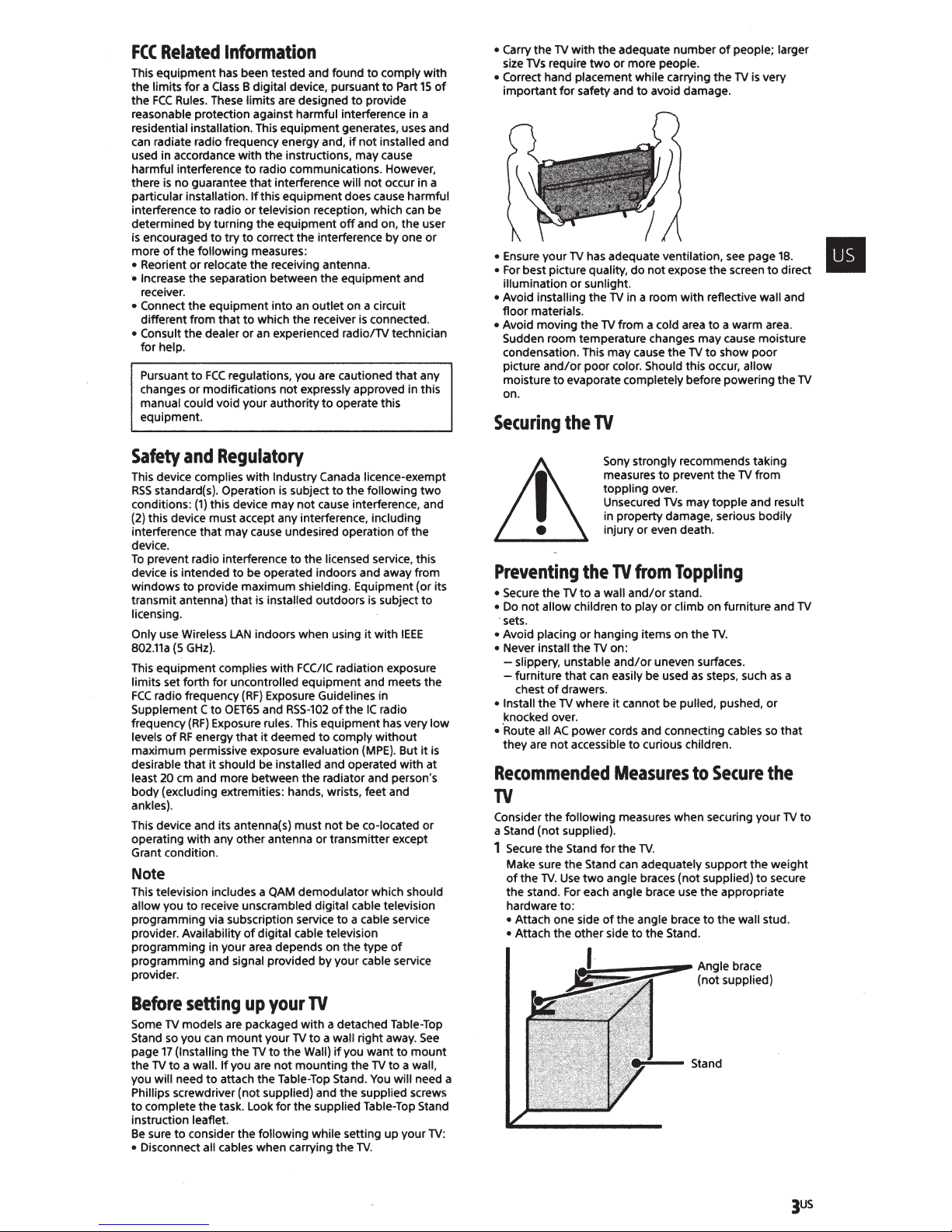
• Carry the
size
Correct hand placement while carrying
•
important
• Ensure your
•
For
illumination
Avoid installing the
•
floor
• Avoid moving
Sudden room temperature changes may cause moisture
condensation. This may cause
picture
moisture
on.
Securing
TV
with
TVs
require
best picture quality, do
materials.
and/or
the adequate
two
or
for
safety and
TV
has adequate ventilation,
or
sunlight.
TV
in a room
the
TV
from a cold area
poor
to
the
color. Should this occur, allow
evaporate completely before powering the
TV
number
more people.
to
avoid damage.
not
expose
with
the
TV
of
people; larger
the
TV
is very
see
page
the
screen
reflective wall and
to
a warm area.
to
show
18.
to
poor
Ill
direct
TV
Safety
This device complies
RSS
conditions:
(2) this device
interference
device.
To
device
windows
transmit antenna)
licensing.
Only
802.11a
This equipment complies
limits set forth
FCC
Supplement C
frequency
levels
maximum permissive exposure evaluation
desirable
least
body (excluding extremities: hands, wrists, feet and
ankles).
This device and its antenna(s) must
operating
Grant condition.
and
Regulatory
with
standard(s}. Operation
(1)
this device may
must
that
may cause undesired operation
prevent radio interference
is
intended
to
provide maximum shielding. Equipment (or its
use Wireless
(5
GHz).
radio frequency
20
for
to
OET65
(RF)
Exposure rules. This
of
RF
energy
that
it
should be installed and operated
em
and more between the radiator and person's
with
any other antenna or transmitter except
Industry Canada licence-exempt
accept any interference, including
to
be operated indoors and away from
that
is
installed outdoors
LAN
indoors when using
with
uncontrolled equipment and meets the
(RF)
Exposure Guidelines in
and
that
it
deemed
is
subject
to
the
not
cause interference, and
to
the licensed service, this
FCC/IC
RSS-102
to
following
is
it
with
radiation exposure
ofthe
IC
equipment
comply
without
(MPE).
not
be co-located or
of
subject
IEEE
radio
has very
But
with
two
the
to
it
Note
This television includes a
allow you
programming via subscription service
provider. Availability
programming in your area depends on the type
programming and signal provided by your cable service
provider.
Before
Some
Stand so you can
page
the
you will need
Phillips screwdriver (not supplied) and
to
instruction leaflet.
Be
• Disconnect all cables when carrying the
to
receive unscrambled digital cable television
setting
TV
models are packaged
17
(Installing
TV
to
a wall.
to
complete
sure
to
consider
the
If
attach the Table-Top Stand.
task. Look
QAM
demodulator which should
of
digital cable television
up
your
TV
mount
the
TV
you are
the
with
your
TV
to
to
the
Wall)
not
mounting
for
the supplied Table-Top Stand
following while setting
to
a cable service
of
a detached Table-Top
a wall right away.
if
you
want
the
TV
You
the
supplied screws
TV.
See
to
mount
to
a wall,
will need a
up
your
low
is
at
TV:
Sony strongly recommends taking
measures
toppling
Unsecured
in property damage, serious bodily
injury or even death.
Preventing
• Secure
•
Do
not
·sets.
Avoid placing
•
• Never install the
-slippery,
-furniture
chest
• Install the
knocked over.
• ·Route all
they
are
the
the
TV
to
allow children
of
a wall
or
hanging items on
TV
unstable
that
can easily be used
drawers.
TV
where
AC
power
not
accessible
on:
cords and connecting cables
Recommended
to
prevent
over.
TVs
TV
from
and/or
to
and/or
it
stand.
play
or
uneven surfaces.
cannot be pulled, pushed,
to
curious children.
Measures
the
may
topple
Toppling
climb on furniture and
the
TV.
as
steps, such
to
Secure
TV
from
and result
or
so
the
TV
Consider the following measures when securing your
a Stand
(not
supplied).
1 Secure
the
Stand
Make sure
of
the stand.
hardware to:
• Attach one side
• Attach
the
the
Stand can adequately support the
TV.
Use
two
For
each angle brace use the appropriate
the
other side
~---~•·
for
the
TV.
angle braces (not supplied)
of
the angle brace
to
the Stand.
to
the
Angle brace
(not
supplied)
Stand
to
wall stud.
TV
as
a
that
TV
weight
secure
to
JUS
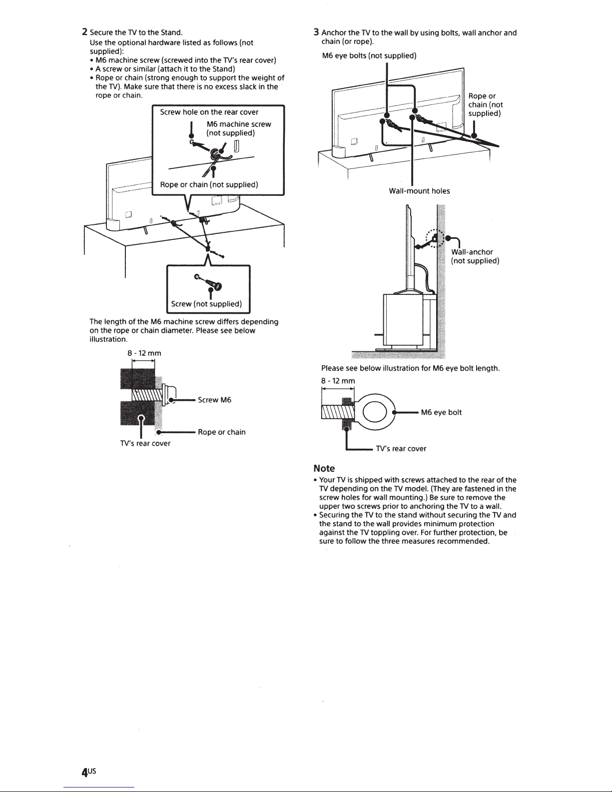
2 Secure the
Use
supplied):
M6 machine screw {screwed into the TV's rear cover)
•
• A screw or similar (attach it
Rope or chain (strong enough
•
the
rope or chain.
TV
to
the
Stand.
the optional hardware listed
to
TV).
Make sure
that
there
Screw hole on
l
as
follows {not
the Stand)
to
support the weight
is
no
excess
slack in the ·
the
rear cover
M6 machine screw
supplied}
(not
_:::_p-
e,
of
Wall-mount holes
Screw {not supplied)
The length
on the rope or chain diameter.
illustration.
of
8-12
TV's
the
M6 machine screw differs depending
mm
rear cover
l"
Please
see
below
Please
8-12
mm
Note
• Your
TV
TV
depending on
holes
screw
upper
two
Securing the
•
the stand
against
sure
to
see
below illustration for M6 eye
is
shipped
with
screws attached
the
TV
for
wall mounting.)
screws prior
TV
to
the wall provides minimum protection
the
TV
toppling over.
follow the three measures recommended.
model. {They are fastened in the
Be
to
to
anchoring
the stand
without
For
bolt
length.
to
the rear
sure
to
remove
the
TV
to
securing the
further protection, be
a wall.
the
TV
of
the
and
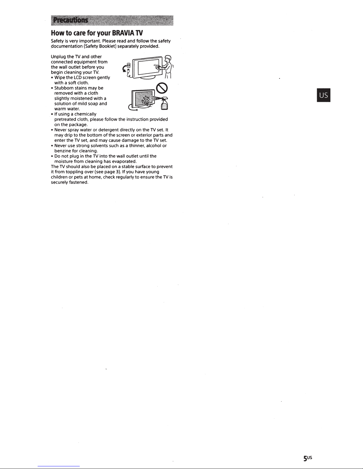
How
to
care
for
your
BRA
VIA
TV
Safety
is
documentation (Safety Booklet) separately provided.
very important. Please read and follow the safety
Unplug the
connected equipment from
the wall outlet before you
begin cleaning your
• Wipe the
with a soft cloth.
• Stubborn stains may be
removed
slightly moistened with a
solution
warm water.
•
If
pretreated cloth, please follow the instruction provided
on the package.
• Never spray water or detergent directly on the
may drip
enter the
• Never use strong solvents such
benzine for cleaning.
•
Do
moisture from cleaning has evaporated.
The
it
from toppling over (see page
children
securely fastened.
TV
and other
LCD
with
of
using a chemically
to
TV
not
plug in the
TV
should also be placed on a stable surface
or
pets at home, check regularly
TV.
screen gently
a cloth
mild soap and
the
bottom
of
set, and may cause damage
the screen or exterior parts and
as
a thinner, alcohol
TV
into the wall outlet until the
3).
If
you have young
to
to
the
ensure
TV
set. It
TV
to
prevent
the
set.
or
TV
is
sus
The
BRA
VIA®
4K
TV
Experience
Thank
you
for
opens
document
Please take a
U.S.A.:
choosing
the
door
will
help
moment
http://productregistration.sony.com
to
the
you
Sony! Your
"4K
TV
Experience."
get
the
to
register
most
your
new
out
TV
Canada: http://www.sony.ca/registration
Four
Steps
to
a
4K
TV
Experience
Set, Source, Sound,
1
Set
Now
that
backlit
accessori
TV
2
To
you
•
This
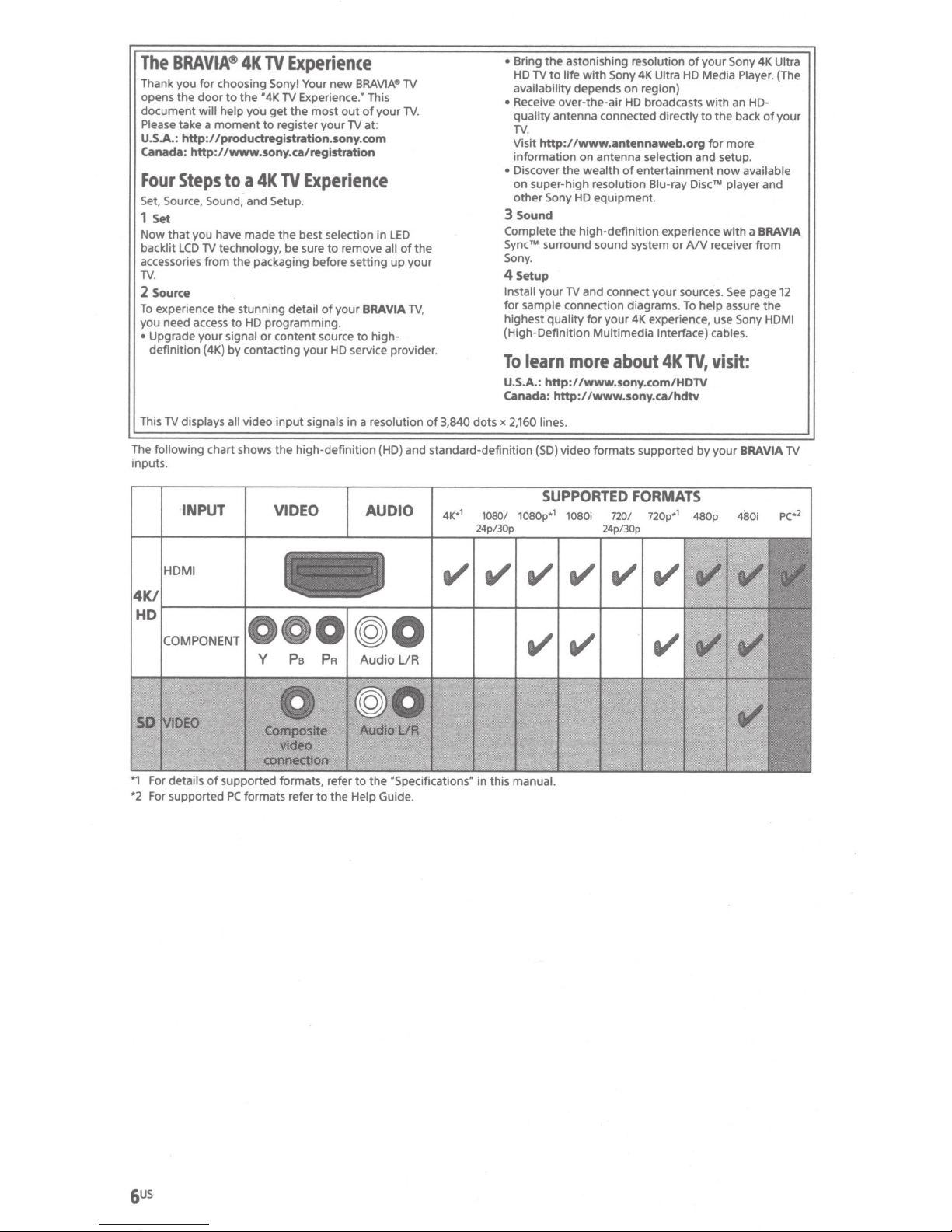
The
inputs.
you have made the best selection in
LCD
es
.
Source
experience the stunning detail
need access
Upgrade
definition
TV
displays all
following
your
and Setup.
TV
technology,
from
the
to
HD
signal
(4K)
by
contacting
video
chart shows
be
sure
to
packaging before setting
programming.
or
content source
input
the
remove
of
your
your
HD
signals
in
high-definition (HD) and standard-definition
BRA
VIA"'
TV
This
of
your
TV
all
VIA
high-
LED
of
up
.
the
your
TV
,
of
at:
BRA
to
service provider.
a resolution
3,840
•
Bring
the
HD
availability depends
•
Receive over-the-air
quality
TV.
Visit
information on antenna selection and setup.
•
Discover
on
other
3
Sound
Complete
Sync™
Sony.
4
Setup
Install
for
highest
(High-Definition
To
U.S.A.:
astonishing resolution
TV
to
life
with
Sony
4K
Ultra
on
region)
HD
antenna connected directly
broadcasts
http://www.antennaweb.org
the
wealth
of
super-high resolution Blu-ray
Sony
HD
the
high-definition experience
surround sound system
your
TV and connect
sample connection diagrams.
quality
for
learn
more
entertainment
equipment.
your
4K
Mu
l
timedia
about
your
experience, use Sony
Interface) cables.
http://www.sony.com/HDTV
Canada: http://www.sony.ca/hdtv
dots
x
2,160
lines.
(SD)
video formats supported by
of
your
HD
Media Player. (The
with
to
the
for
now
Discru player and
or
AIV
receiver
sources.
To
help
4K
TV,
visit:
your
Sony
an HD-
back
more
available
with
See
assure
BRA
4K
of
a
BRAVIA
from
page
the
HDMI
VIA
Ultra
your
12
TV
INPUT
HOM
I
*1
For details
*2 For supported
of
supported
PC
formats refer
VIDEO
formats, refer
to
the
AUDIO
to
the
"Specifications·
Help Guide.
1080/
1080p*
24p/30p
in
this manual.
SUPPORTED
1
1080i
720
24p/30p
FORMATS
/ 720p*
1
480p
4SO
i
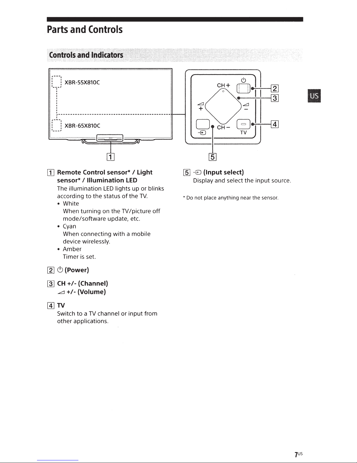
Parts
fi*M•
:
~.
___
.;.9-.vv.-
:
~.
___
[I]
and
~
XBR-SSX810C
,
I
t
I
I
I
I
I
I
I
l
I
,--------~---w•------·----------••••--•--•-~----
1
~
XBR-65X810C
,
Remote Control sensor* I Light
sensor*
The illumination
according
Controls
I Illumination
LED
lights up or blinks
to
the status
LED
of
the
TV.
...:::::::1
+
[§]
-EJ
Display and select the
*Do
not
• White
When turning on the
mode/software
Cyan
•
TV
/picture
update, etc.
off
When connecting with a mobile
device wirelessly.
• Amber
is
Timer
set.
CH+
(Input select)
place
anything
near
input
the
source.
sensor.
11]
c9
(Power)
~
CH
+1-
(Channel)
....c:1
+I- (Volume)
@]TV
Switch
other applications.
to a TV
channel or input from
JUS
0
r"""'"b
5V
=
D
1.
5
A MAX,.
II
·D
1----""111
·D
Hi:lmi
IR
Serial
II
!ARcl
iN
@
IN
Control
@
+{I]
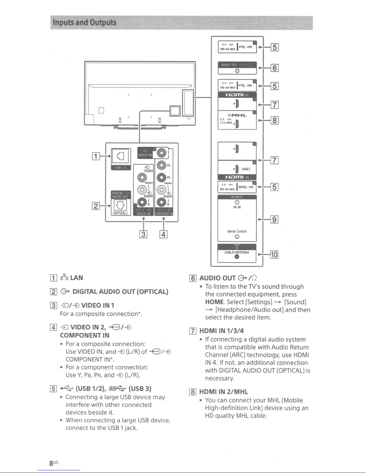
[1]
n
LAN
[2]
(3.
DIGITAL AUDIO OUT (OPTICAL)
~
-8/-B
For a composite connection*.
@]
-8
VIDEO IN
VIDEO IN
2,
-+3/-B
1
COMPONENT IN
•
For a composite connection:
Use
VIDEO
COMPONENT
• For a
Use
Y,
[ID
~
(USB
•
Connecting a
interfere
devices beside it.
•
When connecting a
connect
IN,
and
IN*.
component
PB,
PR,
and
112),
S~
large
with
other
to
the
USB
-B
connection:
-B
(LIR)
of
(L/R).
(USB
3)
USB
device may
connected
large
USB
1 jack.
-+3/-B
device,
CABLE/ANTENNA
•
[ID
AUDIO OUT
•
To
listen
the
connected equipment, press
HOME.
--+
[Headphone/
select
[1]
HDMI
•
[ID
HDMIIN
•
IN
If
connecting a digital
that
is
Channel
IN
4.
with
DIGITAL
necessary.
You
can connect
High-definition Link) device using an
HD
quality
G+
to
the
Select
the
desired item.
1/3/4
compatible
(ARC)
If
not, an
AUDIO
2/MHL
MHL
10
TV's sound
[Settings]-+
Audio
technology,
additional
your
cable.
out]
audio system
with
Audio
OUT
MHL (Mobile
through
[Sound]
and
then
Return
use
HDMI
connection
(OPTICAL)
is
sus
lj]
REMOTE
IR
IN
REMOTE
• These jacks are
external control signal. Enables
extended control
RS232C
jacks.
IR
of
Serial Control: connect
terminal
Take
•
headphones
system.
•
If
[BRA VIA Sync settings]
available.
[1Q]
lr
CABLE/ANTENNA
Connect
* When connecting mono equipment, connect
the L {MONO) audio jack.
Serial Control
via
IN
: connect
the
home
of
care
[RS232C
to
your
for
receiving
of
the
theIR
IN
and Serial Control
to
the
controller.
the
home
to
not
connect
or
an external audio
control]
cable
is
or
TV
using
IR
out
terminal
to
the
controller.
to
set
to
[On],
is
not
antenna.
the
RS232C
II
to
gus

Using
Remote
Control
Remote
IR
(infrared) Remote
Control
Parts
Control
Description
~
Color
Execute correspondent function
time.
DISPLAY
Display
program/input
NETFLIX
Access the
HELP
Display Help Menu.
@]
ACTION
Display a
TV
Switch
other applications.
GUIDE*
Display
buttons
information about the channel/
you are viewing.
N
MENU
list
to
a
1
the
NETFLIX"
of
TV
channel or
digital
online
contextual functions.
program guide.
service.
input
at
that
from
[I]
INPUT
Display
POWER/C)
Turn on
mode).
SYNC
Display
CJ
Display
[2]
Number
Use
-
digital channels.
PIC OFF*
Turn the picture off,
remains on.
and
or
MENU
the
(Twin
two
with
turn
picture/PIP}*
buttons
the
2
select
off
BRA
VIA
pictures
0-9
buttons
the
input
source.
the
TV
(standby
Sync
Menu.
1
2
*
simultaneously.
to
select
while
sound
BACK
Return
HOME
Display
DISCOVER
Bring
content.
to
previous screen.
the
TV
up
the
+1+1+1+/(j)
[§]
VOL+/-
Adjust the volume.
JUMP
Jump back and
channels
between the current
and the last channel
selected.
MUTING
Mute
the
CH
Select the
the
sound.
+/-
(Volume}
or
sound.
channel.
Home Menu.
Content Bar
{Item
inputs. The
select/Enter}
forth
between
channel
or
Press
to
TV
alternates
input
again
search
two
or
input
that
to
restore
for
was
1QUS
(§]AUDIO
Change
currently being viewed.
CCI
Turn subtitles on or
feature
[1]
~,~,
Operate media contents on
connected
device.
the
language
SUBTITLE
is
available).
....
, ...... ,
BRA
for
the
program
off
{when the
•• , .....
VIA Sync-compatible
,.
TV
and
WIDE
Change
the
screen format.
FOOTBALL
Turn Live Football Mode on or
the feature
*1
The location, availability and function
remote control button may vary depending on
your country/region/TV model.
*2
Twin Picture/PIC
from July
PIC
OFF
software upgrade. Make sure your
connected
network connection, you will be able
download the software from the Sony support
website using your
upgrade, please visit the Sony support
website.
is
available).
OFF
function will be available
2015.
You
will receive Twin Picture/
function automatically
to
the Internet.
PC.
If
For
details on
as
you
off
of
a network
TV
is
do
not
to
how
{when
have a
to
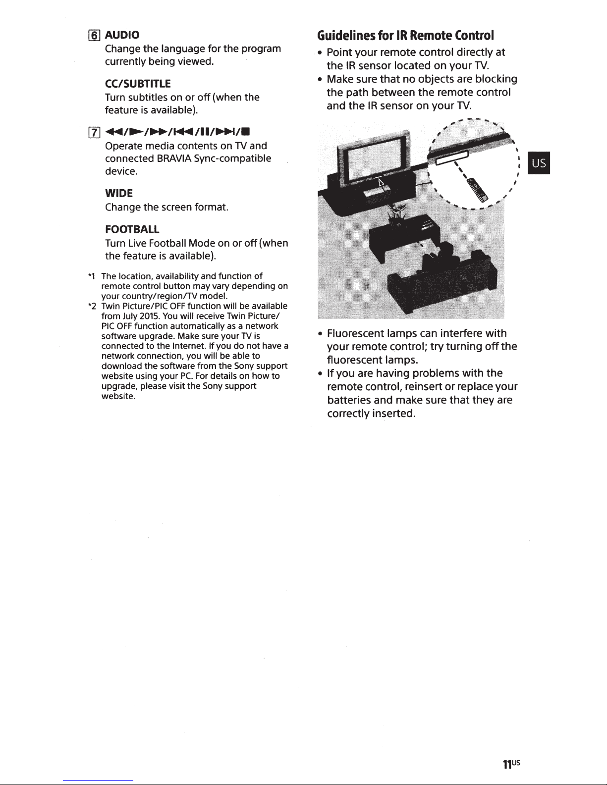
Guidelines
for
IR
Remote
Control
• Point your remote control directly at
the
IR
sensor located on your
• Make sure
that
no objects are blocking
TV.
the path between the remote control
and the
• Fluorescent lamps can interfere
your remote control;
IR
sensor on your
try
TV.
turning
with
off
fluorescent lamps.
•
If
you are having problems with
remote control, reinsert
batteries and make sure
or
that
the
replace your
they are
correctly inserted.
II
the
Connecting
For
more information on connections, refer
to
the Help Guide.
Note
• When connecting
Antenna,
tightening
•
For
only (The availability depends on region).
To
•
press
input
the
FMP-X1,
select an
INPUT.
the
the
TV
the
cable
to
the
finger
tighten
connection can damage
connect
input
device connected
it
to
only, over
the
Cable/
HDMIIN 2 jack
to
the
the
TV.
TV,
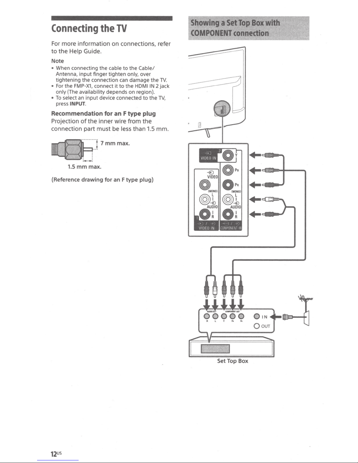
Showing
COMPONENT
asetTopBoxwlth
connection
Recommendation
Projection
connection part must be less than
mrr-A:--f
II1II....S1
(Reference
1.5
of
:--:
mm
drawing
for
an F type
the
inner wire from
7
mm
max.
for
an F type
max.
plug)
plug
the
1.5
mm.
+--=-~
+-c:~~~~~~-+-"""
.....
+-~_.....,.
..
...,
~..,
12US
OIN
Qour
Set Top Box
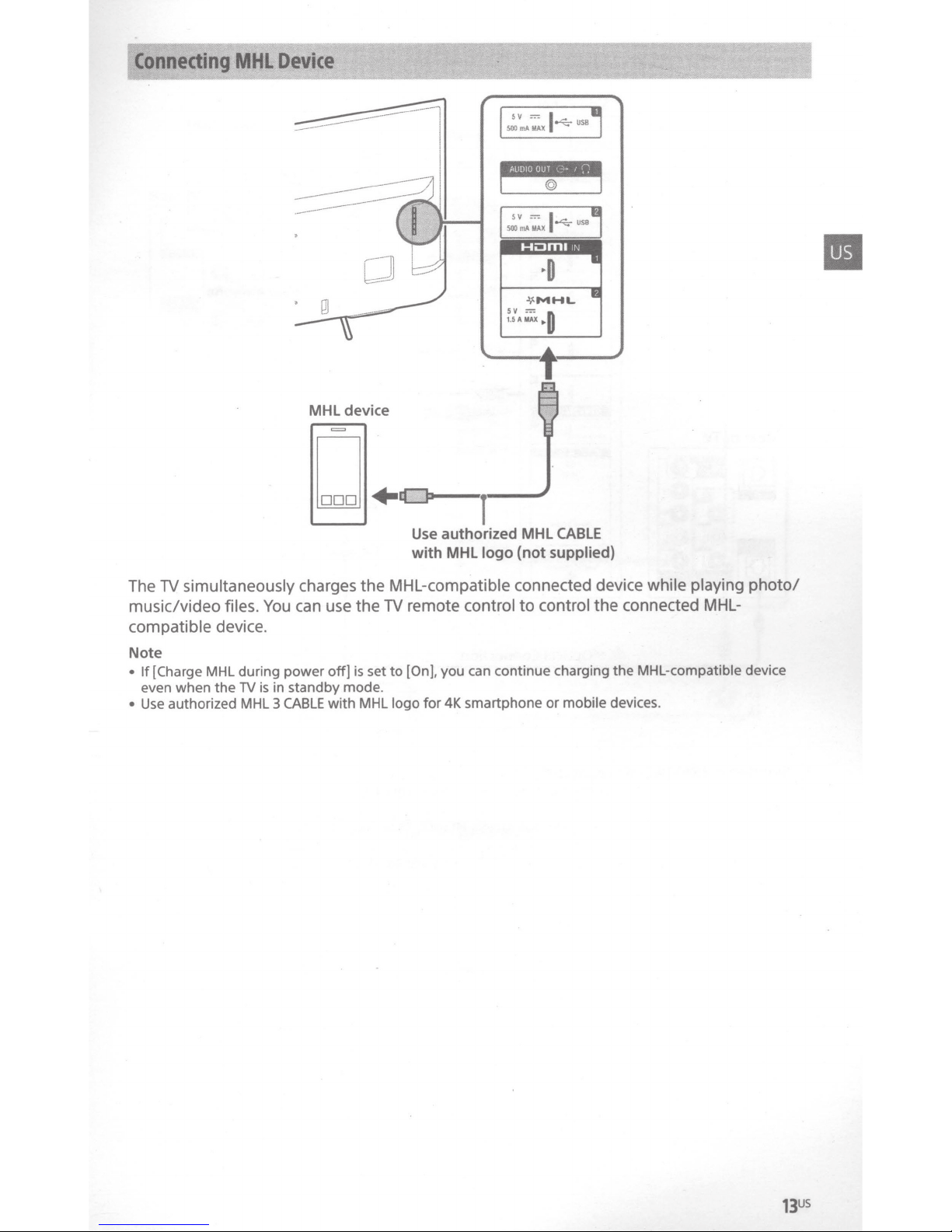
MHL
llik1Jf~~~~·
*''t
rt:
device
m
5V
I
SllOmAMAX
sv
5AMAX
1.
=
=
I
~USB
0
•
,
ili:l:!.
~
...
:
'
~~\%!
·.
•
•·•··
,w
WI
simultaneously
TV
The
music/video files.
compatible device.
Note
[Charge
If
•
even when
Use
•
MHL during power
the
authorized
TV
MHL
D
charges
can use
You
off]
in standby mode.
is
with MHL
CABLE
3
Use
with
MHL-compatible
the
remote
TV
the
is set to
[On],
logo
for
CABLE
authorized
MHL
control
you can continue charging the MHL-compatible device
4K smartphone
MHL
supplied)
(not
logo
connected device while playing
control
to
or
the connected
mobile
devices.
photo/
MHL-
1
*
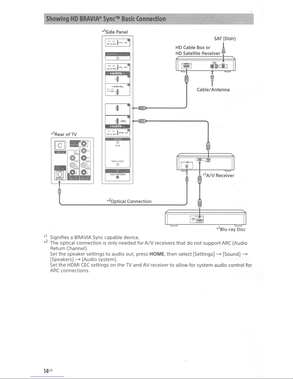
Side Panel
HD
Cable Box
HD
Satellite
SAT
(Dish)
or
Recei~ver
!
·
1
*
Rear
of
TV
·0
-\<
MHL
1SAMAX
.,.
"=
0
©
IR
Serial
eontrot
©
CA8lEIANT£NNA
•
2
•
optical
•
IN
Connection
~I
~t
Cable/
g[j]
, -
v
Antenna
*1 Signifies a
2
•
The optical connection
Return Channel).
Set
the
[Speakers]Set the
ARC
BRA
VIA Sync capable device.
speaker settings
[Audio system].
HDMI
CEC
connections.
is
o·nly needed
to
audio out, press HOME,
settings on
the
TV
for
and
A/V
AV
receivers
receiver
=
then
to
that
select
allow
do
not
support
[Settings]-
for
system audio control
ARC
(Audio
[Sound]-
for
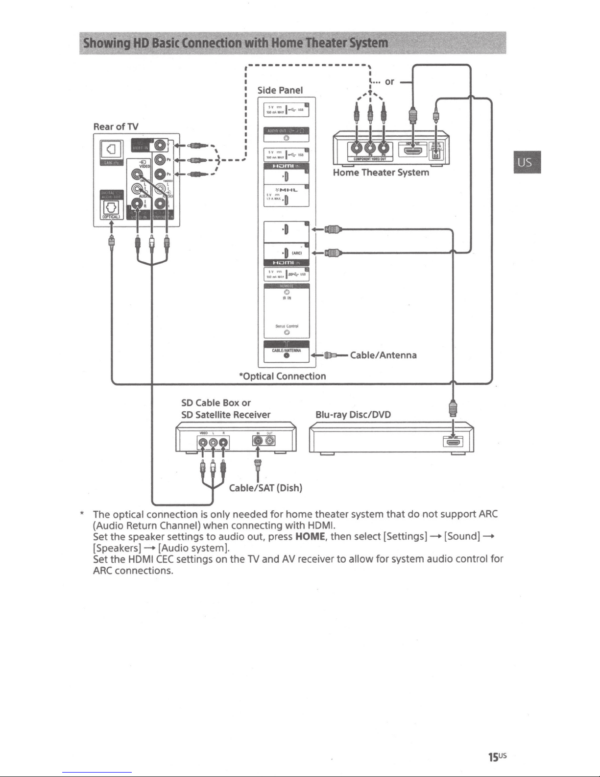
RearofTV
.------------------,
Side
Panel
~
~~~
~~
--
,
,
' i l
I
~
...
t,
or
~-
' I
~--4----"
I
~-
SO
Cable
Box
SO
Satellite Receiver Blu-ray Disc/DVD
~v
....
:..J~-·
•
·D
-\<
MHL
..
•
0
1.5-..u
"=
*Optical Connection
or
Home Theater
Ill=-
Cable/ Antenna
System
Ff
~i~.~~t
_
~
u
v.
Cable/SAT
* The optical connection is only needed
(Audio Return Channel) when connecting
Set the speaker settings
[Speakers)-+ [Audio system].
CEC
Set the HDMI
ARC
connections.
settings on the
to
audio out, press HOME,
TV
~rr
c=
(Dish)
for
and
~~~--------------~~~~
home
theater system
with
HDMI.
then
AV
receiver
to
select
allow
~
that
do
not
support
[Settings)-+
for
system audio control
[Sound]-+
ARC
for
15US
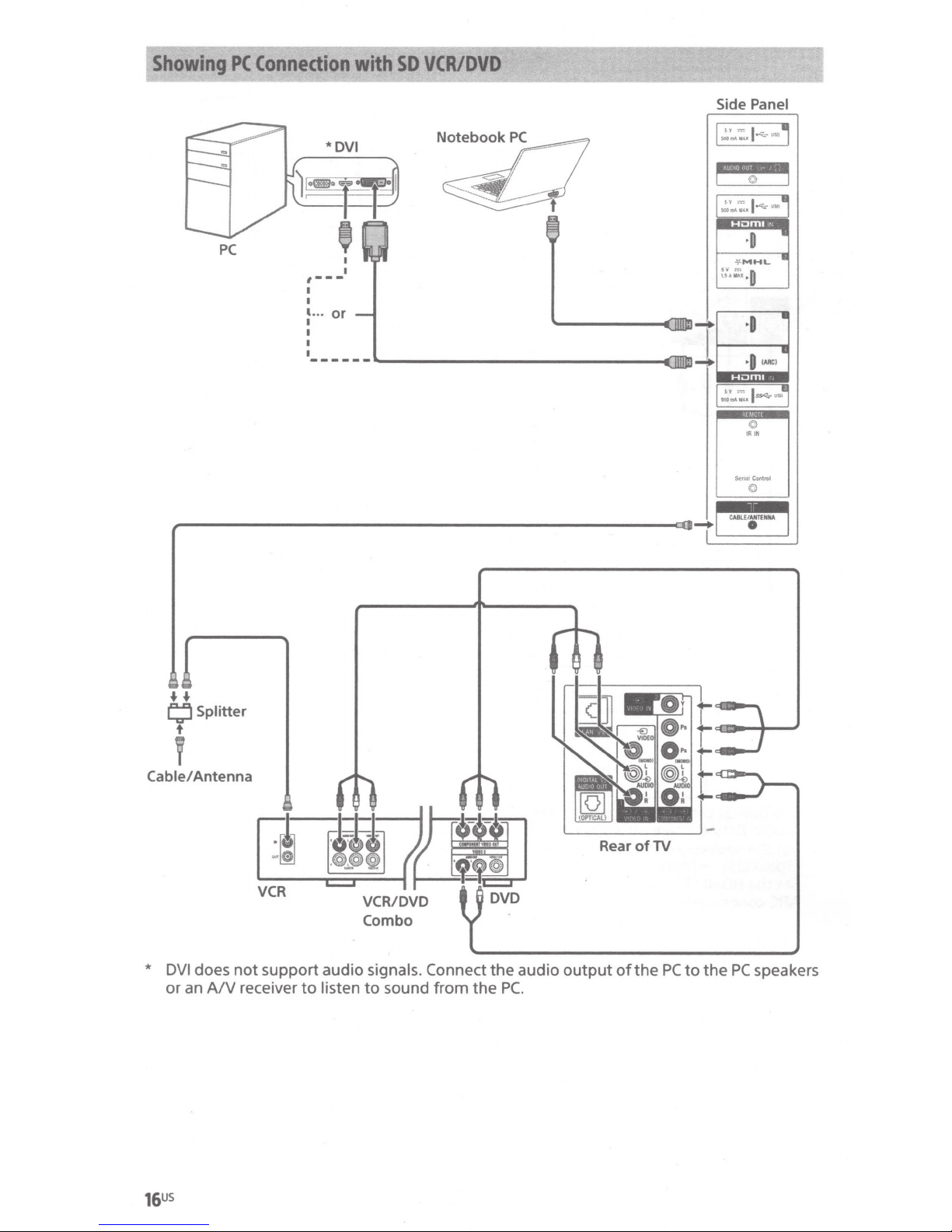
Showing
PC
PC
Connection
,---
1
I
'···
I
I
I
I
with
I
I
or
------~------------------------~mm-+
SD
VCRIDVD
Side Panel
1.::
..
:.
1
~-
"'
j
~I
©I
I
I.::
..
:.
1·
"'-
...
j
•
·0
-\<
MHL
•
~:.:;~
·0
I
E@
I
"=
I ,
' tc<OIIIAW.•
$9Ci.7
:JSII
-
©
IR
IN
krlaiC~
©
CABlE/ANTENNA
I
•
[ I
++
9 Splitter
Cable/
Antenna
'
*
DVI
does
or
an
A/V
not
support
receiver
audio signals. Connect
to
listen
to
sound
from
the
the
PC.
audio
Rear
output
of
of
the
TV
PC
to
the
PC
speakers
16US
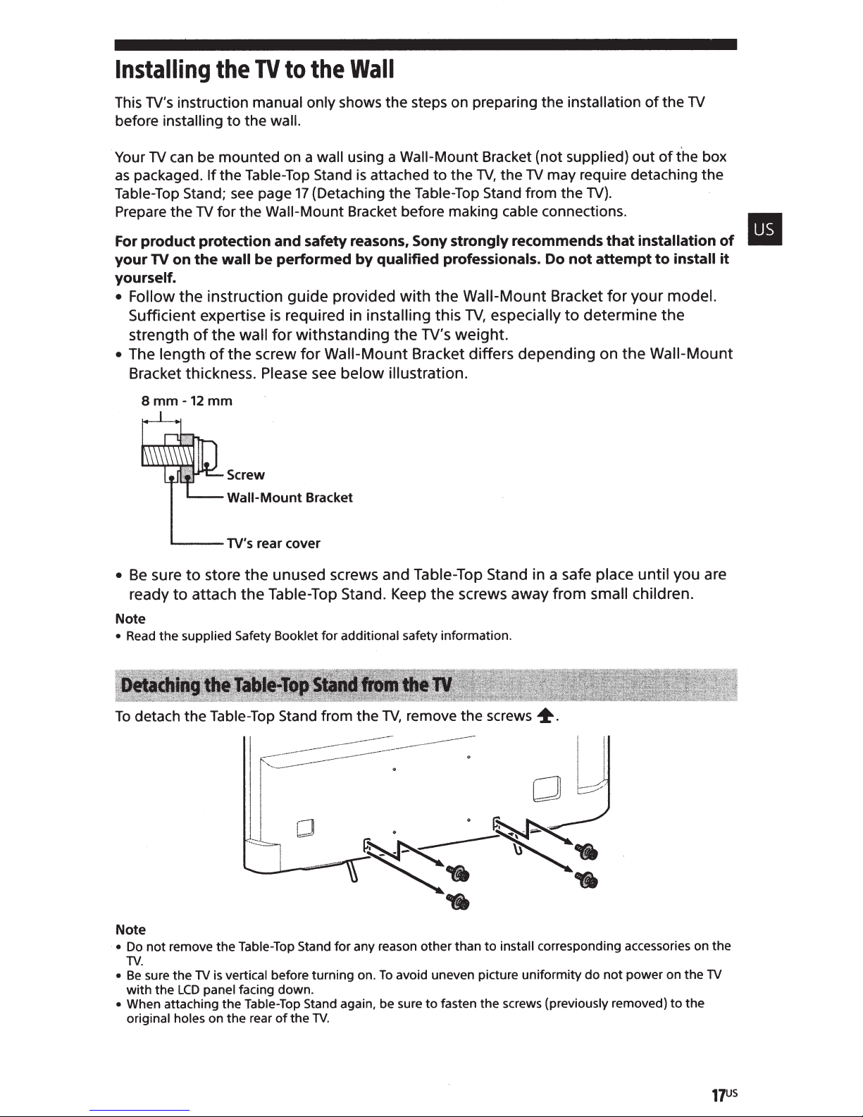
Installing
This TV's instruction
before
Your
as
Table-Top
Prepare
installing
can be mounted on a
TV
packaged.
the
the
to
the
If
Stand; see page
the
for
TV
to
TV
manual only
wall.
the
Table-Top
17
Wall-Mount
Wall
the
steps on preparing
shows
wall
Stand
(Detaching
the
using a
is
Bracket before making
Wall-Mount
attached
Table-Top
the
to
Bracket (not
the
TV,
the
Stand from the
cable
installation
the
supplied)
may require detaching
TV
TV).
connections.
of
out
the
of
TV
the
box
the
safety reasons, Sony
For
your
product
on
TV
protection
wall
the
and
performed
be
qualified
by
professionals. Do
yourself.
• Follow the instruction guide provided with the
Sufficient expertise
the wall
strength
The length
•
of
the screw for
of
is
Bracket thickness. Please
mm
-12
mm
8
Screw
Wall-Mount
store the unused screws and Table-Top Stand in a safe place until you are
to
sure
Be
•
Table-Top Stand.
ready to attach
Note
supplied Safety Booklet
the
Read
•
the
required in
withstanding the
for
Wall-Mount Bracket differs depending on the
below illustration.
see
Bracket
additional safety information.
for
installing
Keep
this
TV's
the screws away from
strongly
recommends
Wall-Mount
especially
TV,
weight.
that
attempt
not
Bracket
for
determine the
to
small
installation
install
to
model.
your
Wall-Mount
children.
of
it
II
Table-Top
not
sure
the
the
remove
TV
the
panel
LCD
the
is
the
on
vertical
the
detach
To
Note
Do
•
TV.
Be
•
with
When attaching
•
original holes
Stand from the
Table-Top Stand
before turning on.
facing down.
Table-Top Stand
of
rear
the
TV,
----
any reason other than
for
To
again, be sure
TV.
screws
to
the
fasten
to
the
remove
-------------
-----
-
avoid uneven picture uniformity
~.
corresponding accessories on the
install
screws (previously removed)
do
not
power on the
the
to
TV
17US
 Loading...