

Sony Bravia KDL-52XBR7 Operating Instructions Manual
Operating Instructions
KDL-52XBR7
BRAVIA
© 2008 Sony Corporation
XB1
Owner's Record
The
model
and serial
rearofthe TV. Record these
at the
numhers
Refertothem
your
in the spaces prO\ided
Sony
dealer
numhers
whenever
you call upon
regarding this TV.
are located
belo\\.
Model Name
Serial No.
CAUTION
To
prevent
electric
shock
and
do not use
extension
unless the
D
Operate
this
polarizedACplug with an
cord.
receptacleorother
blades
can
the
TV only on 120 V AC.
blade exposure.
outlet
be fully inserted.
DeclarationofConformity
Trade
Name:
Model:
Responsible
Address:
San
Diego.CA92127
I
Telephone
This
FCC
following
,
may
this
device
received.
~
cause
SONY
KDL-52XBR7
Party:
16530
device
rules.
two
not
cause
including
undesired
Sony
Via Esprillo.
Number:
Operationissubject to the
must
858-942-2230
complies
with part15of
conditions: ( I)
hmmful interference. and (2)
accept
interference that
operation.
Electronics Inc.
U.S.A.
This
any
interference
the
device
may
NOTIFICATION
This
equipment
comply
device.
These
limits
reasonable
interferenceina residential installation. This
equipment
radio
frequency
used in
cause
harmful
communications.
However.
interference
installation.
harmful
reception.
the
equipment
encouragedtotry to correct the intelt"erence by
oneormoreofthe following measures:
D
Reorientorrelocate the receiving antenna.
D
Increase
equipment
D
Connect
circuit
receiverisconnected.
D
Consult
TV
PursuanttoFCC
cautioned
expressly
not
void
your
equipment.
For CustomersinCanada
This
Class
Canadian
has been tested and found to
with
the
pursuant
accordance
technician
limits for a
to Part15of
are
designed
protection
generates.
energy
interference to radio •
there
is no guarantee that
will
not
If
this
interference
equipment
which
can be
off
and
the
separation
and
the
equipment
different
the
dealeroran experienced
for help.
that
anv
approvedTnthis manual could
authoritytooperate
B digital apparatus complies with
ICES-003.
Class
B digital
the FCC Rules.
to provide
against harmful
uses
and
can
and.ifnot installed and
with the instructions. mav
;ccur
in a particular
does
to radioortelevision
determined
on. the user is
receiver.
from that to which the
regulations. you are
changesormodifications
cause
between
into an outlet on a
this
radiate
by turning
the
radial
CAUTION
Use the following
following
TV-stand.
Sony
Wall-Mount
Bracket
No.
Model
Sony
TV
Stand
Model No.
Use with
orTVstands
possibly result
other
To Customers
Sufficient
the specified TV. Be
installation to a Sony
contractor
during
the installation.
Note
This
television
which
should
unscrambled
programming
cable service provider. Availability
cable
television
dependsonthe typeofprogramming
providedbyyour
Licensing Information
Macintoshisa
registered
HDM!.
the
Multimedia
registered
LLC.
Fergason
U.S. Patent No.
U.S. Patent No. 6.816.141
Manufactured
Laboratories.
are
In
related marks are
Gemstar-TVGuide
oneofits affiliates.InCanada.TVGuide is a
registered mark
used under license by
International. Inc. .
TheTVGuideOnScreen
manufactured
Guide
affiliates.
TheTVGuideOnScreen
by
patents
6.396.546:
Gemstar-TV
its subsidiaries.
Gemstar-TV
related affiliates are not in any way liable for
the
schedule
GuideOnScreen
service availability'
shall
andlor
damagesinconnection
mailabilityofthe
information
Screen systenl.
Patent
trademarksofDolby
the United States.TVGuide
International. Inc.
oneormoreofthe
4.908.713:
accuracyoravailabilityofthe program
informationorother
Gemstar-TV
its related affiliates be liable for any
Sony
WALL-MOUNT
TVs
SonyTVModel No.
KDL·52XBR7
SU-WL500
WS-S10LS
WALL-MOUNT
may
cause
in
expertiseisrequired
and
pay
includesaQAM
allow
digital
via
trademarkofApple Inc"
in
the U.S.
HDMllogo
Interface
trademarksofHDMI
under
Dolby
of
under
5.940.073:
Guide
Guide
or
other
instability and
injury.
sure
to subcontract the
dealerorlicensed
adequate
subscription
programminginyour
cable
Properties.
5.717.422
registered
Transcontinental
6.498.895:
Internationallnl'.
system
in
Guide
program
attention to safety
youtoreceive
cable
television
service
and
other
and
High-Definition
are
trademarks
LLC:
license
from Dolby
and
the
double-D
Laboratories.
marks
International.
Gemstar-TVGuide
system
license
from Gemstar-
and/or
systemisprotected
following
6.D9.7lJ4to
International. Inc.
and
your
area.Inn'O
International. Inc.
with
the accuracy
schedule
data
in theTVGuide
only with the
BRACKET
servicetoa
6.850.693:
datainthe
cannot guarantee
or
BRACKETS
for installing
demodulator
of
digital
area
and signal
provider.
countries.
or
Licensing.
symbol
and
other
of
Inc. andlor
Inc" and is
is
oneofits
United States
andlor
andlorits
TV
event
or
TV
On
Blu-ray Disc
"BRA
Motionllow. BRA VIA Sync.
MICRO
trademarks
Corporation. " 0
"XrossMediaBar"isa trademarkofSony
Corporation.
Corporation and Sony
Entertainment Inc.
"PLA
and
o·Ps.risa trademark
Entertainment Inc.
Adobe
of
Adobe
States 'IndioI' other countries.
DLNA®. the DLNA Logo and DLNA
CERTIFlED!1I are
or
certification marksofrhe Digital Living
Network Alliance.
[I]
i.s
a trademark.
VIA"
and
BRAVIA.
VAULT. ando,x·.\·. Color" are
or
re~istered
"XMB"
YSTATION"isa registered trademark
is
a re!.!istered trademarkora
Sy~tems
IncorporatedinUnited
trad;marks.
S-Force.
m.
DMe'.
mark>ofSon\
is a trademarkofSon\
Computer
~I'
SOIll
Computer
trademark
service marks.
HIGH-DEFINITION
TELEVISION
DOLBY
DIGITAL I
•
For Customers in the United
States
Lamp
mercury. Disposal
materials may be regulated
to environmental considerations.
For
information, please contact
local authoritiesorthe
Electronic Industries Alliance
(www.eiae.org).
in this product contains
of
these
disposalorrecycling
due
your
2
Four
The
Sound,
Picture
TV
Home
1.
Installing
Stepstoa Full HD Experience: Set,
Source, and Setup 4
Quality
and
Aspect
Menu:
XMBTM
the
TV 6
Ratio 4
(XrossMediaBar) 5
Carrying the TV
Preparation for Wall-Mount Bracket 6
When Installing the TV Against a
Wallar
Enclosed Area 7
Bundling the Connecting Cables 8
Securing the TV 8
2.
Locating
3.
Connecting
Inputs
the
and
Outputs
TV 12
Cable System or VHF/UHF Antenna
System
Cable System and VHF/UHF Antenna
System
HD Cable BoxlHD Satellite Box 12
PC
Other Equipment 15
4.
Setting
Initial
Inserting
When
TV
Controls
Remote
Up
Setup
Batteries
Using
Control
the
the
Channel
into
Remote
Button
List
-
the
Remote
Control
Description
Control
Indicators
Programming
the
Remote
Control.
Programming Other Equipment.. 25
Auto Backlight. 25
Backlight Time Out 25
Reset the Remote Control 25
Manufacturer's
Code
List
Sony Equipment Codes 26
Other Manufacturer Equipment Codes 26
Using
Other
Equipment
with
Your
Remote
Control
Favorites
Displaying Favorites 28
Navigating Favorites 28
Adding to Favorites 28
Removing from Favorites 28
Quick Setup Guide (separate volume)
Provides a varietyofoptional equipment
connection diagrams.
10
12
12
14
16
18
18
18
19
24
25
26
27
28
Background
Navigating Background TV 29
DLNA Certified™
Enjoying
USB
Photos
Port
Using USB Equipment.. 29
Removing USB Equipment... 29
USB Equipment Functionality 29
Photo
6
Accessing Photos 30
Navigating through Photo 30
Photo Options
Music
Accessing Music
Navigating through Music 33
Music Options 33
HowtoUseTVGuide
Using
Using
Using
BRAVIA
DIGITAL MEDIA PORT
P&P
To Enter P&P and PIP 37
To Change Inputs or Channels (P&P) 37
To Change Channels (PIP) 37
To Exit from P&P and PIP 37
Media
Category
;:;
Adjusting TV Settings 38
~
Viewing Photos 38
nListening to Music 38
d Watching TV 38
€l
Accessing External Inputs 38
Navigating
on
XMBTM
Settings
TV
" Product Support 40
Q(J)
ClocklTimers Settings 40
ttl
Picture Settings
Q~I)Sound
9±J
Screen Settings .44
'i:::f
Channel Settings .46
~
Closed Captions (CC) Settings .47
tQ Parental Lock Settings 47
ttl External Inputs Settings 50
'=
HDMI Settings 50
~
Network Settings
Y.J
General Setup Settings
1~
Initial Setup 52
"Otlier:Information
~~
~
"
Troubleshooting
Specifications
Index
Customer Support
United States
http://www.sony.com/tvsupport
Canada
http://www.sony.ca/support
On-line Registration
United States
http://productregistration.sony.com
Canada
http://www.SonyStyle.calregistration
TV 29
Photo
and
Media
Music
Player
through
On Screen 34
Sync
with
Control
for
HDMI. 36
Adapter
and
PIP Features 37
Icons
through
TV
Home
Menu
Descriptions
Settings .43
."
~
29
29
30
31
32
32
36
38
39
40
41
51
51
53
57
58
3
Thank
seeonyour BRAVIA TV is onlyasgoodasthe quality of the signalitreceives.Toexperience the
stunning detail of your new
can receive and display HD programming from:
Contact your cable
To
you
for purchasing this Sony
BRAVIA
• Over-the-air broadcasting via HD-quality antenna
• HD cable sUbscription
• HD satellite subscription
• Blu-ray
learn more about
Disc™
or
player or other HD compatible external equipment
satellite provider for information on upgrading to HD programming.
HDTV,
BRAVIA®
TV,
you
visit:
high-definition television. The quality of the image
need accesstoHD
programming.
Your
you
BRAVIA TV
U.S.A. http://www.sony.com/HDTV
Canada http://www.sonystyle.calhd
Jl!.illlll!\~k;dii$("r'··.'
The Four Steps to a Full HD Experience: Set, Sound, Source, and Setup
Along with your BRAVIA TV set, a complete HD system requires an HD sound system, a
source of HD programming and proper setup connections. This manual explains basic setup
connections (see page 12). The Quick Setup Guide, enclosed separately, illustrates how to
connect other optional equipment.
Picture Quality and Aspect Ratio
You
can enjoy crisp, clear images, smooth movement and high-impact visuals from 1080 HD
signals. When you compare a high-definition signal to a standard analog signal, you will notice
a big difference.
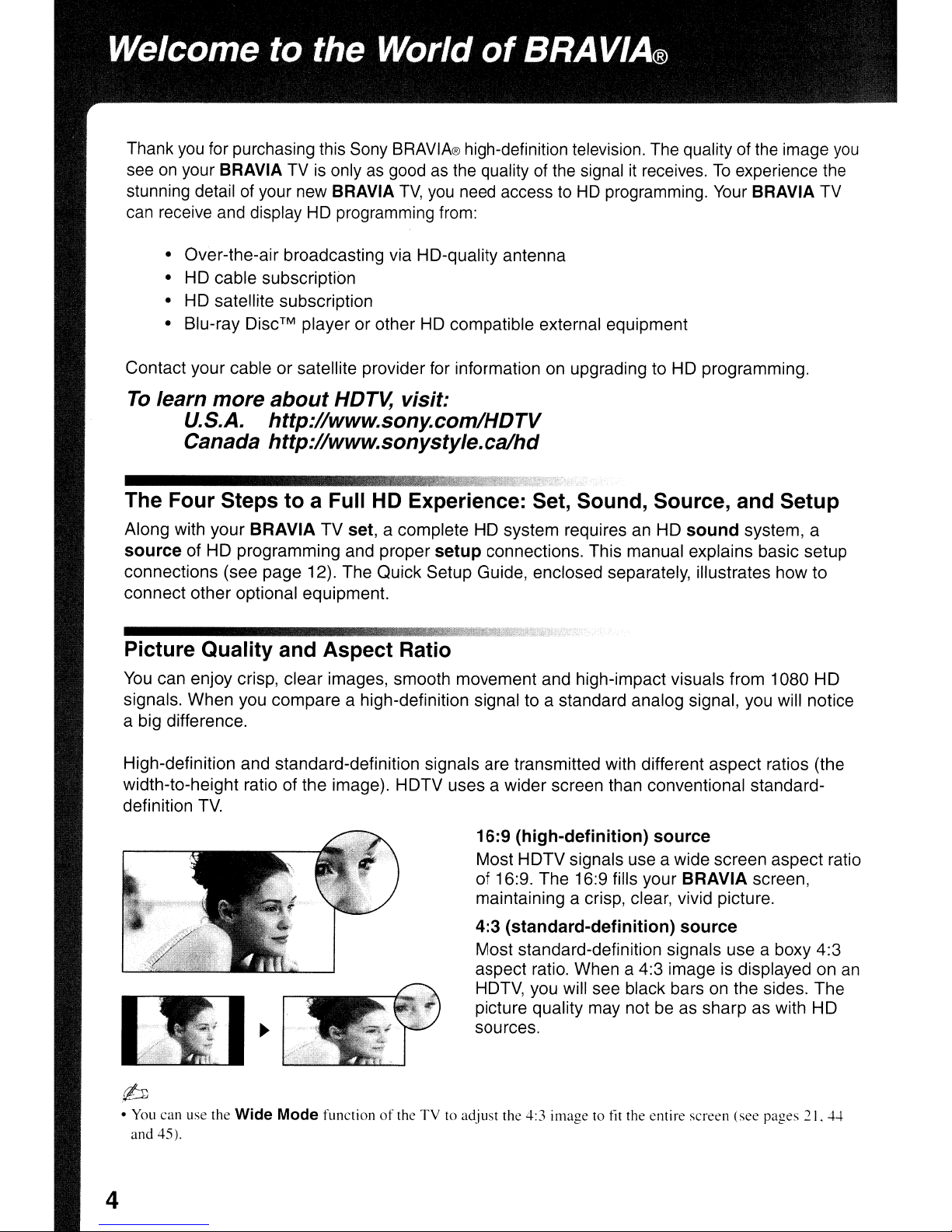
High-definition and standard-definition signals are transmitted with different aspect ratios (the
width-to-height ratio of the image). HDTV uses a wider screen than conventional standarddefinition
(bJ
•
You
and 45).
TV.
16:9 (high-definition) source
Most HDTV signals use a wide screen aspect ratio
of 16:9. The 16:9 fills your
maintaining a crisp, clear, vivid picture.
4:3 (standard-definition) source
Most standard-definition signals use a boxy 4:3
aspect ratio. When a 4:3 image is displayed on
HDTV, you will see black barsonthe sides. The
picture quality may not be as sharp as with HD
sources.
can use the Wide Mode functionofthe TVtoadjust the 4:3 imagetotit the entire screen (see pages 21.
BRAVIA screen,
4-1-
an
4
TV
Home
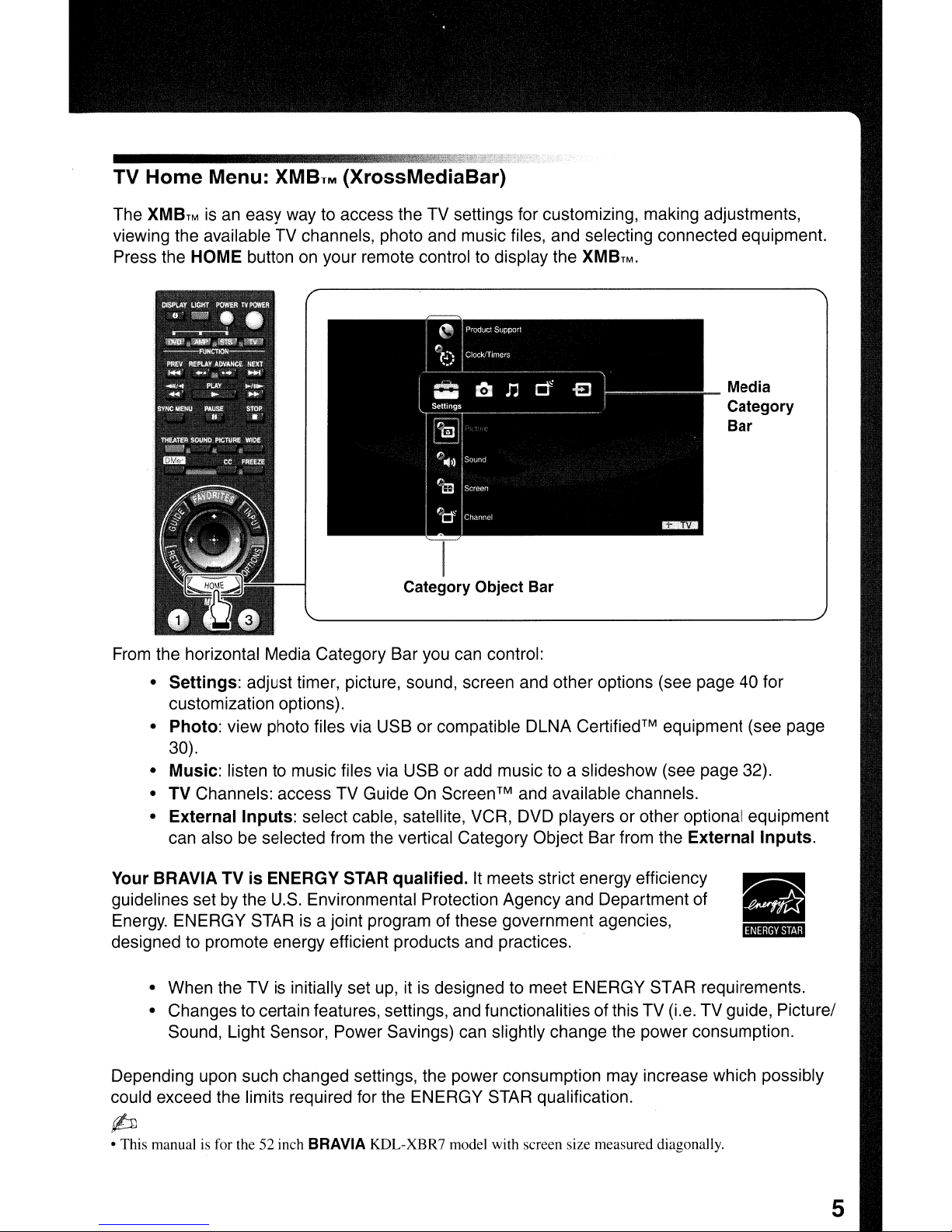
The
XMBTMisan easy way to access the TV settings for customizing, making adjustments,
viewing the available TV channels, photo and music files, and selecting connected equipment.
Press the HOME button on your remote control to display the
Menu:
XMBTM
(XrossMediaBar)
XMBTM.
Media
Category
Bar
I
Category Object Bar
From the horizontal Media Category Bar you can control:
Settings:
•
customization options).
• Photo: view photo files via USB or compatible DLNA
30).
•
Music:
• TV Channels: access TV Guide
•
External
can also be selected from the vertical Category Object Bar from the
Your BRAVIA TVisENERGY STAR
guidelines set by the
Energy. ENERGY STAR is a joint program of these government agencies,
designed to promote energy efficient products and practices.
• When the TV is initially set up, it is designed to meet ENERGY STAR requirements.
• Changes to certain features, settings, and functionalities of this TV (i.e. TV guide, Picture/
Sound, Light Sensor, Power Savings) can slightly change the power consumption.
Depending upon such changed settings, the power consumption may increase which possibly
could exceed the limits required for the ENERGY STAR qualification.
adjust timer, picture, sound, screen and other options (see page 40 for
Certified™
listen to music files via USB or add music to a slideshow (see page 32).
On
Screen™ and available channels.
Inputs:
select cable, satellite, VCR, DVD players or other optional equipment
qualified.Itmeets strict energy efficiency
U.S.
Environmental Protection Agency and Department of
equipment (see page
External
Inputs.
p
• This manual is for the 52 inch BRAVIA KDL-XBR7 model with screen size measured diagonally.
5
1.
Installing the TV
This TV can be mounted on a wall using a WallMount
separately). This section will explain:
• How
• Preparation for a Table-Top stand
• Preparation for a Wall-Mount Bracket
• Installation against a wall or enclosed area
• Bundling the connecting cables
• Securing the TV
Carrying the
Bracket or placed on a TV stand (each sold
to
carry the TV
TV
Preparation for Wall-Mount Bracket
• For product protection and safety reasons,
Sony strongly recommends that you use the
Wall-Mount Bracket model designed for your
of
TV and the wall-mounting
be performed by a Sony dealer or licensed
contractor.
• Sufficient expertise is required in installing this
TV,
especially to determine the strengthofthe
wall for withstanding the
your TV should
TV's
weight.
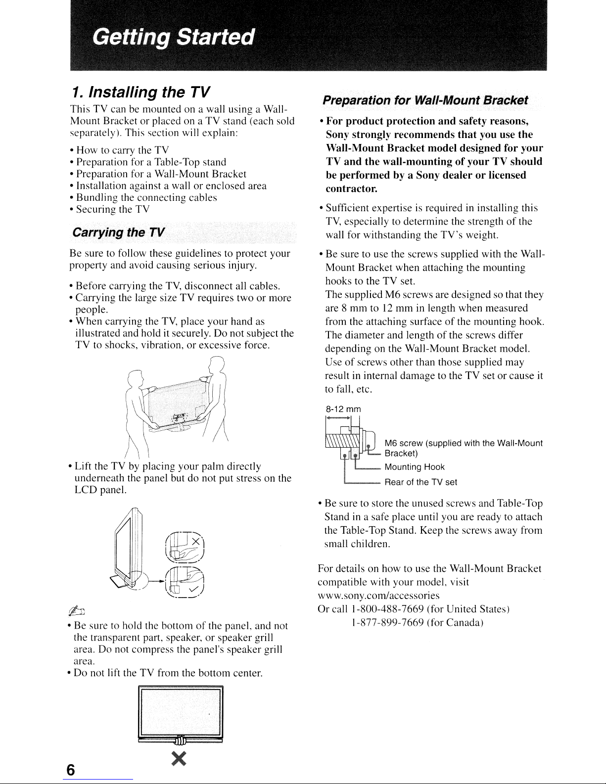
Be sure to follow these guidelines to protect your
property and avoid causing serious injury.
TV,
• Before carrying the
• Carrying the large size
people.
When
•
illustrated and hold
TV
• Lift the TV by placing your palm directly
underneath the panel but do not put stress on the
LCD
carrying the
to shocks, vibration,orexcessive force.
panel.
disconnect all cables.
TV
requires twoormore
TV,
place your hand as
it
securely.Donot subject the
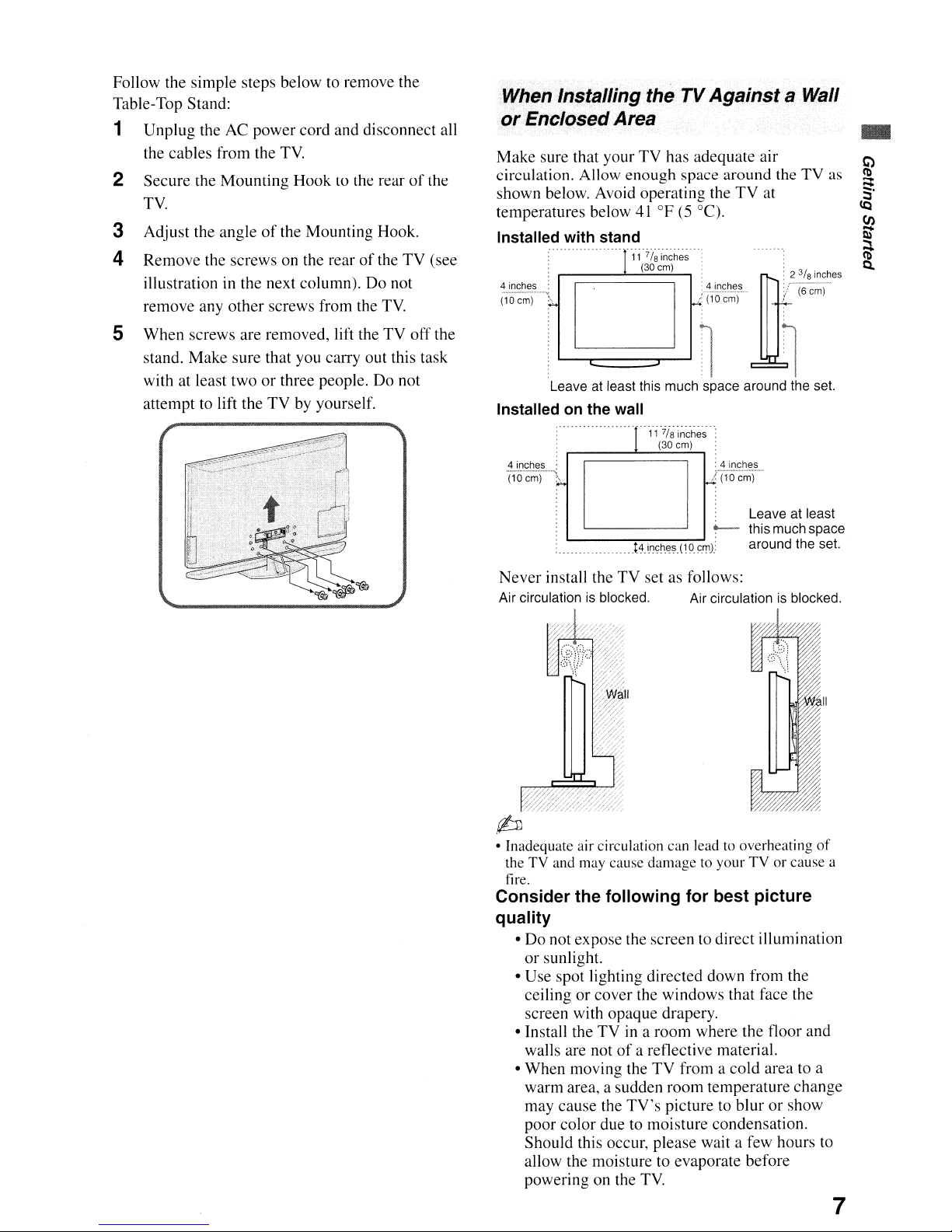
• Be sure to use the screws supplied with the WallMount Bracket when attaching the mounting
hooks to the TV set.
The supplied
are 8 mm to
from the attaching surface
The diameter and length
depending on the Wall-Mount Bracket model.
Use
of
result in internal damage to the TV set or
to
fall, etc.
8-12
mm
1.--
• Be sure to store the unused screws and Table-Top
Stand
in
the Table-Top Stand. Keep the screws away from
small children.
M6
screws are designed so that they
12
mm in length when measured
of
the mounting hook.
of
the screws differ
screws other than those supplied may
cause
M6 screw (supplied with the Wall-Mount
Bracket)
Mounting Hook
__
Rear of the TV set
a safe place until you are ready to attach
it
~
• Be sure to hold the bottomofthe panel, and not
the transparent part, speaker,
area. Do not compress the panel's speaker grill
area.
Do
not lift the TV from the bottom center.
•
x
6
or
speaker grill
For details on how to use the Wall-Mount Bracket
compatible with your model, visit
www.sony.comlaccessories
Or
call 1-800-488-7669 (for United States)
1-877-899-7669 (for Canada)
Follow the simple steps below to remove the
Table-Top Stand:
1
Unplug
the cables from the TV.
2 Secure the
TV.
3 Adjust the angle
4 Remove the screws on the rear
illustration in the next column).
remove any
the AC power cord and disconnect all
Mounting
other
Hook to the rearofthe
of
the Mounting Hook.
of
Do
screws from the
the
TV.
TV
not
(see
When Installing the
or
EnclosedArea
Make sure that your
circulation. Allow enough space
shown below. Avoid operating the
temperatures below
Installed with stand
111
~":o~)'
.).
D
TV
TV
has adequate air
41°F
(5 °C).
7/
inches
e
~)g:~,\,
Againsta Wall
around
TV
the TV as
at
~::::t
-
5 When screws are removed, lift the
stand. Make sure that you carry out this task
with at least two
attempt to lift the TV by yourself.
or
three people.Donot
TV
off
the
Leave at least this much space around the set.
Installed on the wall
- -----T1
D
L..--__-__- -
Never
install the
Air circulationisblocked. Air circulationisblocked.
\~i
~~)h~S:
~_<!_i':1~J::I~~
~
(10 cm)
: Leaveatleast
~
__
-;.t-:-4_,..i.nc-:-_~_-e~-:(-:19:-'.c.r!1J:
TV
set as follows:
this much space
around the set.
• Inadequate air circulation can lead to overheating
theTVand may cause
fire.
Consider the following for best picture
quality
•Donot expose the screen to direct illumination
or
sunlight.
• Use spot lighting directed down from the
or
ceiling
screen with opaque drapery.
• Install the
walls are not
When
•
warm area, a sudden room temperature change
may cause the
poor color due to moisture condensation.
Should this occur, please wait a few hours to
allow the moisture to evaporate before
powering on the
cover the windows that face the
TVina room where the floor and
moving the
damagetoyourTVor
of
a reflective material.
TV
from a
TV's
picture to blur or show
TV.
cold
cause a
area to a
of
7
Bundling the Connecting Cables
You
can
bundle the connecting cables as illustrated
below.
b
• Do not bundle the AC
power cord with other
connecting cables.
Securing the TV
Sony strongly
measures to prevent the
over. Unsecured TVs
in
result
injury
or
Prevent the TV from Toppling Over
o Secure the
o
Do
not allow children to play or climb on
furniture and
TV
D Avoid placing
D Never install the
• slippery, unstable and/or uneven surfaces.
• furniture that
such as a chest
D Install the
pushed,
TV
or
knocked over.
o Route all AC
cables so that they are not accessible to
curious children.
recommends
property damage, serious bodily
even death.
to a wall
TV
sets.
or
hanging items on the
TV
can
of
where it
power
and/or
on:
easily be used as steps,
drawers.
cannot
cords
TV
may
and
taking
from toppl i
topple and
stand.
be pulled,
connecting
ng
TV.
Use a Sony TV Stand
Use a Sony specified
follow the instruction manual provided with the
Sony
TV
stand.
If
a Sony specified
the following
recommended
TV
stand (see page2)and
TV
stand is not used, consider
measures.
Recommended Measures to Secure the TV
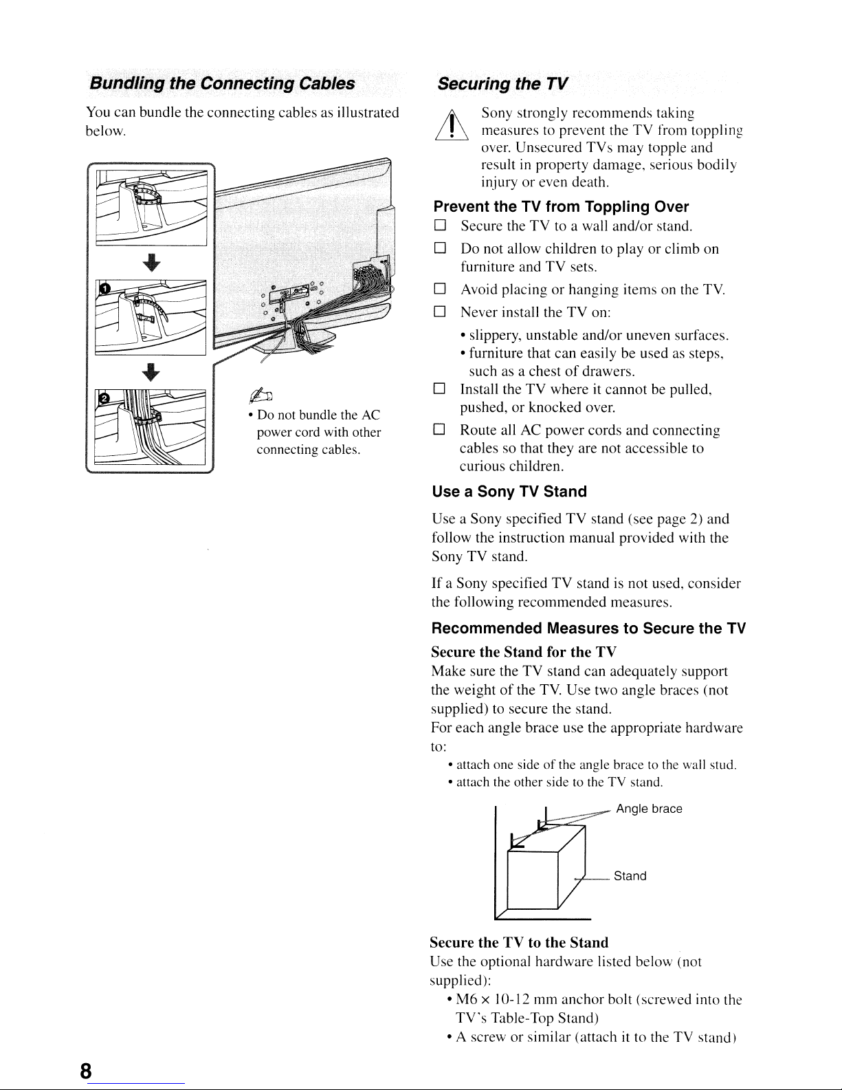
Secure the Stand for the TV
Make sure the
the weight
supplied) to secure the stand.
For each angle brace use the appropriate hardware
to:
• attach one sideofthe angle brace to the wall stud.
• attach the other side to the TV stand.
of
TV
stand can adequately support
the
TV.
Use
two angle braces (not
Angle brace
Stand
8
Secure the TV to the Stand
Use the optional hardware listed below (not
supplied):
mm
• M6 x 10-12
TV's
Table-Top Stand)
• A screw or similar (attach it to the TV stand)
anchor
bolt (screwed into the
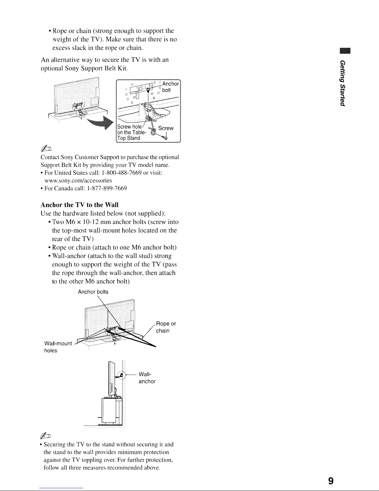
• Ropeorchain (strong enough to support the
weight
excess slack
An alternative way to secure the TV is with an
optional Sony Support Belt Kit.
of
the TV). Make sure that thereisno
in
the rope or chain.
p
Contact Sony Customer Support to purchase the optional
by
Support Belt Kit
• For United States call: 1-800-488-7669 or visit:
www.sony.comlaccessories
• For Canada call: 1-877-899-7669
Anchor the TV to the Wall
Use the hardware listed below (not supplied):
• Two
M6
the top-most wall-mount holes located on the
rear
of
• Rope
• Wall-anchor (attach to the wall stud) strong
or
enough to support the weight
the rope through the wall-anchor, then attach
to the other
providing your TV model name.
x 10-12 mm anchor bolts (screw into
the TV)
chain (attachtoone M6 anchor bolt)
of
the TV (pass
M6
anchor bolt)
Anchor bolts
•
Wall-mount
holes
p
• Securing the TV to the stand without securing it and
the stand to the wall provides minimum protection
against the TV toppling over. For further protection,
follow all three measures recommended above.
Rope or
chain
Wallanchor
9

2.
Locating Inputs and Outputs
Rear of TV
-,J
/-~,
HomilN
1,--
__
1
.....-.:.1
DIGITAL
A88l0
(OPTICAL)
1
VIDEO
L
IMONDI
I
AUDIO
I
R
2
[[}11----~9
DC5V=
O.7A
MAX
Olo!PORT
,....-----
~
CABLE/ANTENNA
10
....
Side Panel
.
r;hJ
121---
......
• ThisTVdisplays all video input signalsina resolutionof1,920 dots x 1,080 lines.
or
• An HOMI
Component video (YPHPR) connectionisrequiredtoview 480i. 480p.
formats. 1080/24p is available only with HOM! connection.
10
nop.
I080i and I080p video
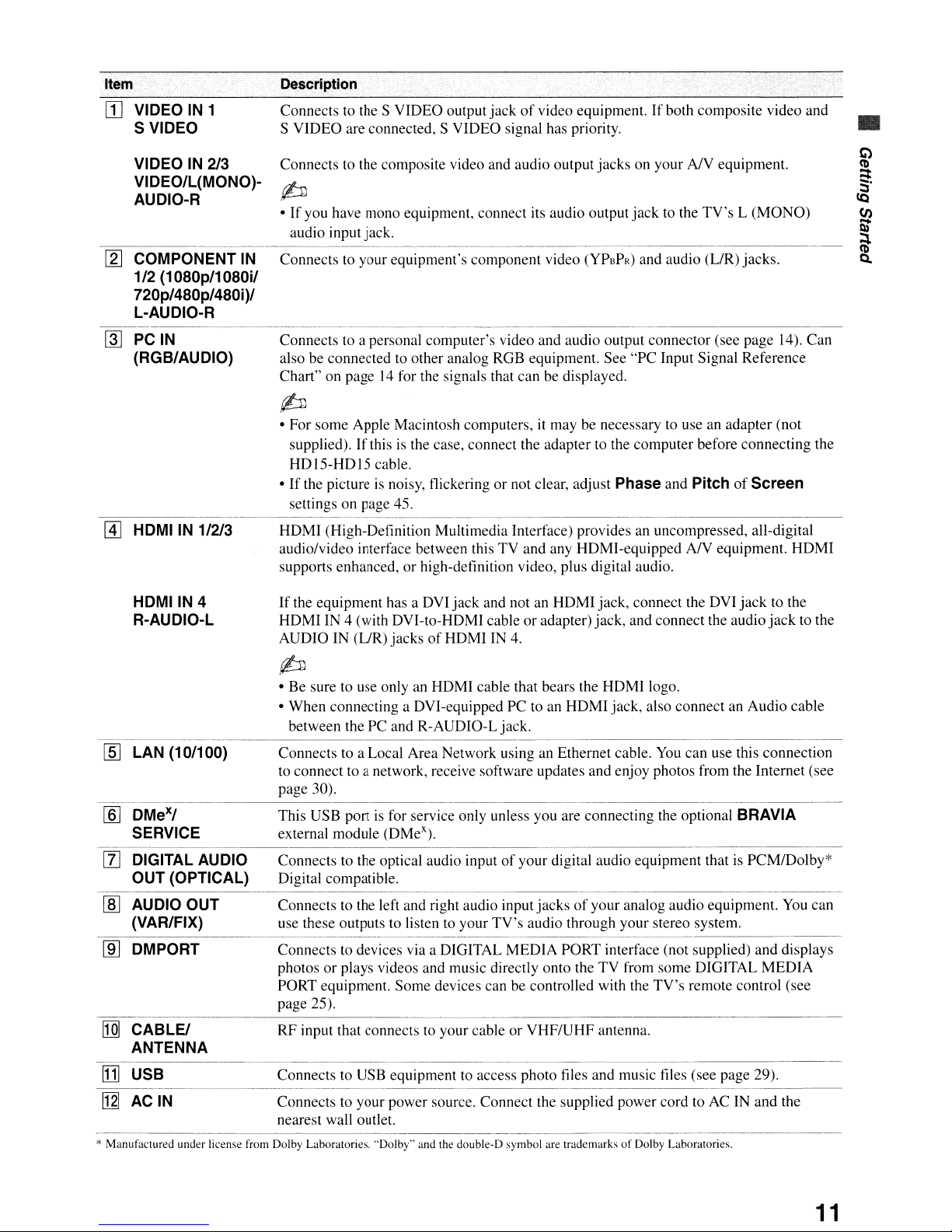
Item
[I]
VIDEO IN 1
S VIDEO
VIDEO IN 2/3
VIDEO/L(MONO)AUDIO-R
Description
Connects to the S VIDEO output
S VIDEO are connected, S VIDEO signal has priority.
Connects to the composite video and audio output jacks on your
jackofvideo equipment. If both composite video and
~
•Ifyou have mono equipment, connect its audio output
audio input jack.
jack
to the
NY
TV's
•
equipment.
L (MONO)
[2J
COMPONENT
1/2(1080pl1
720p/480p/480i)1
L-AUDIO-R
~
PCIN
(RGB/AUDIO)
-------------
[4]
HDMIIN
HDMIIN
R-AUDIO-L
Connects to your equipment's component video
IN
(YPSPR)
and audio (LIR) jacks.
080il
Connects to a personal computer's video and audio output connector (see page 14). Can
also be connected to other analog RGB equipment. See "PC Input Signal Reference
14
Chart" on page
for the signals that can be displayed.
~
• For some Apple Macintosh computers,itmay be necessary to use an adapter (not
If
supplied).
HDI5-HDI5
•
If
the pictureisnoisy, flickering or not clear, adjust Phase and
settings on page 45.
this is the case, connect the adapter to the computer before connecting the
cable.
PitchofScreen
----------------------~----
1/2/3 HDMI (High-Definition Multimedia Interface) provides an uncompressed, all-digital
NY
audio/video interface between this TV and any HDMI-equipped
supports enhanced, or high-definition video, plus digital audio.
If
4
the equipment has a DVI jack and not an HDMI jack, connect the DVI
or
HDMI IN 4 (with DVI-to-HDMI cable
of
AUDIO IN (L/R) jacks
HDMI IN 4.
adapter) jack, and connect the audio
equipment. HDMI
jack
to the
jack
~
• Be sure to use only an HDMI cable that bears the HDMI logo.
• When connecting a DVI-equipped PC to an HDMI jack, also connect an Audio cable
between the PC and R-AUDIO-L jack.
to the
lID
LAN (10/100)
[§]
DMexl
SERVICE
---_.
[l]
DIGITAL AUDIO
OUT
(OPTICAL)
lID
AUDIO
(VAR/FIX)
OUT
ill] DMPORT
[Q]
CABLEt
ANTENNA
[j]
USB
[12J
AC IN
* Manufactured under license from Dolby Laboratories. "Dolby" and the double-D symbol are trademarks
Connects to a Local Area Network using an Ethernet cable.
to connect to a network, receive software updates and enjoy photos from the Internet (see
page 30).
is
This USB port
external module (DMe
Connects to the optical audio inputofyour digital audio equipment that is PCM/Dolby*
Digital compatible.
Connects to the left and right audio input jacks
use these outputs to listen to your
Connects to devices via a DIGITAL MEDIA PORT interface (not supplied) and displays
photos or plays videos and music directly onto the TV from some DIGITAL MEDIA
PORT equipment. Some devices can be controlled with the
page 25).
RF input that connects to your cable or VHF/UHF antenna.
Connects to USB equipment to access photo files and music tiles (see page 29).
Connects to your power source. Connect the supplied power cord to AC IN and the
nearest wall outlet.
for service only unless you are connecting the optional BRAVIA
x
).
of
your analog audio equipment.
TV's
audio through your stereo system.
You
can use this connection
TV's
remote control (see
of
Dolby Laboratories.
You
can
11
3.
Connecting the TV
Cable System
or
VHF/UHF Antenna
System
You can enjoy high-definition and standarddefinition digital
your
area) along with standard-definition analog
programming.
programming
(if
available in
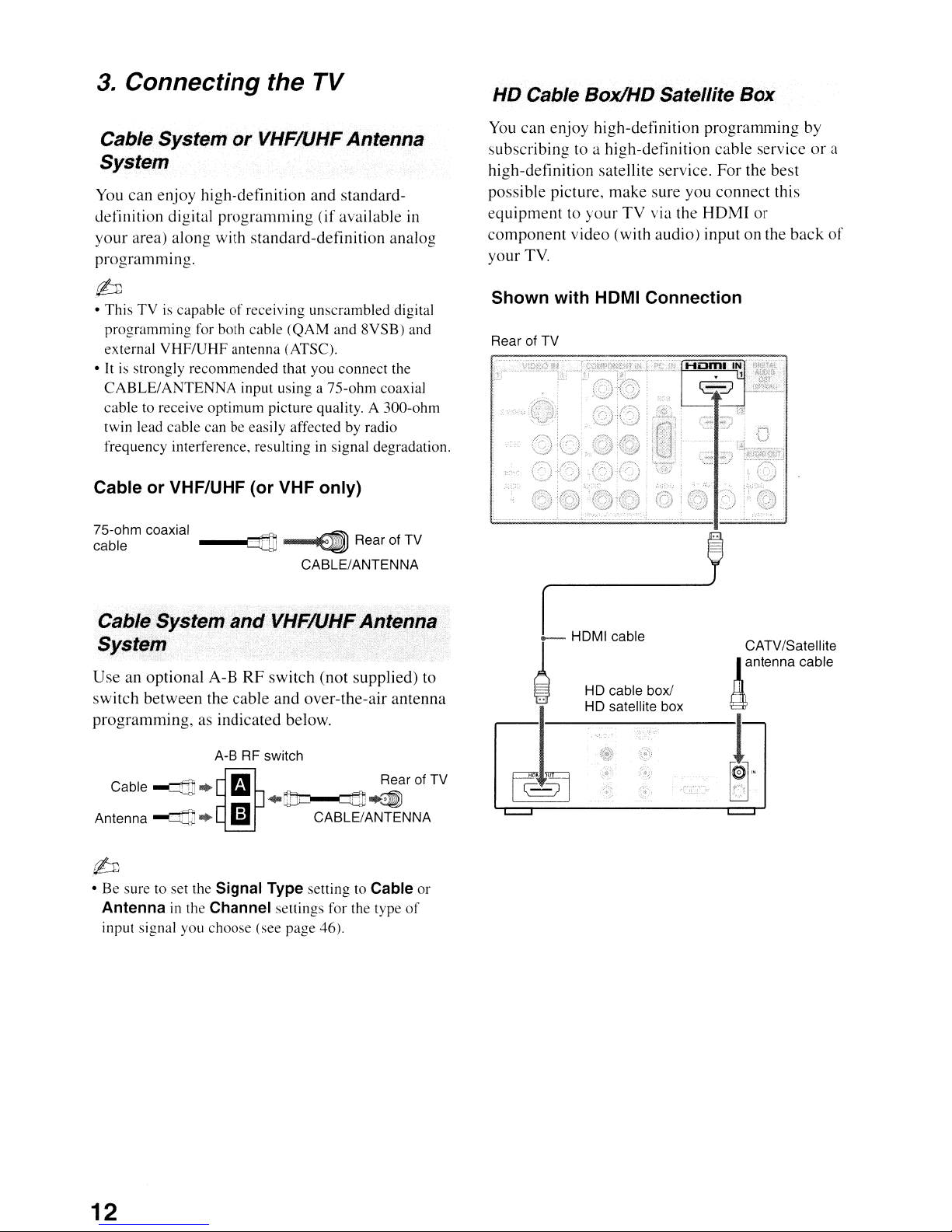
HD Cable BoxlHD Satellite Box
You
can enjoy high-definition
subscribing to a high-definition cable service
high-definition satellite service.
possible picture, make sure you
equipmenttoyour
component
your TV.
video (with audio) input on the
TV
via the
programming
For
the best
connect
HOMI
this
or
by
back
or
a
of
• This TViscapableofreceiving unscrambled digital
programming for both cable (QAM and 8VSB) and
external VHF/UHF antenna (ATSC).
•
It
is
strongly recommended that you connect the
CABLE/ANTENNA
cable to receive optimum picture quality. A 300-ohm
twin lead cable can be easily affected by radio
frequency interference, resulting in signal degradation.
Cable or VHF/UHF (or VHF only)
75-ohm coaxial
cable
Cable System
input using a 75-ohm coaxial
~
and
--4
CABLE/ANTENNA
VHF/UHFAntenna
Rear of TV
System
Use
an optional A-B
switch
programming,
between the cable and over-the-air antenna
RF
switch
as indicated below.
(not
supplied) to
Shown with HOMI Connection
Rear of TV
..
CATV/Satellite
!antenna
cable
A-B RF switch
Cable
~
Antenna
~*
*,'
Ii)
-.rJJ=
CABLE/ANTENNA
Rear of TV
LlQ!1"~
.r/-:JJ
•Besure to set the Signal Type setting to Cable or
Antenna
input signal you choose (see page 46).
in
the Channel settings for the type
of
t
~
...
~
...
"
lQJ.
12
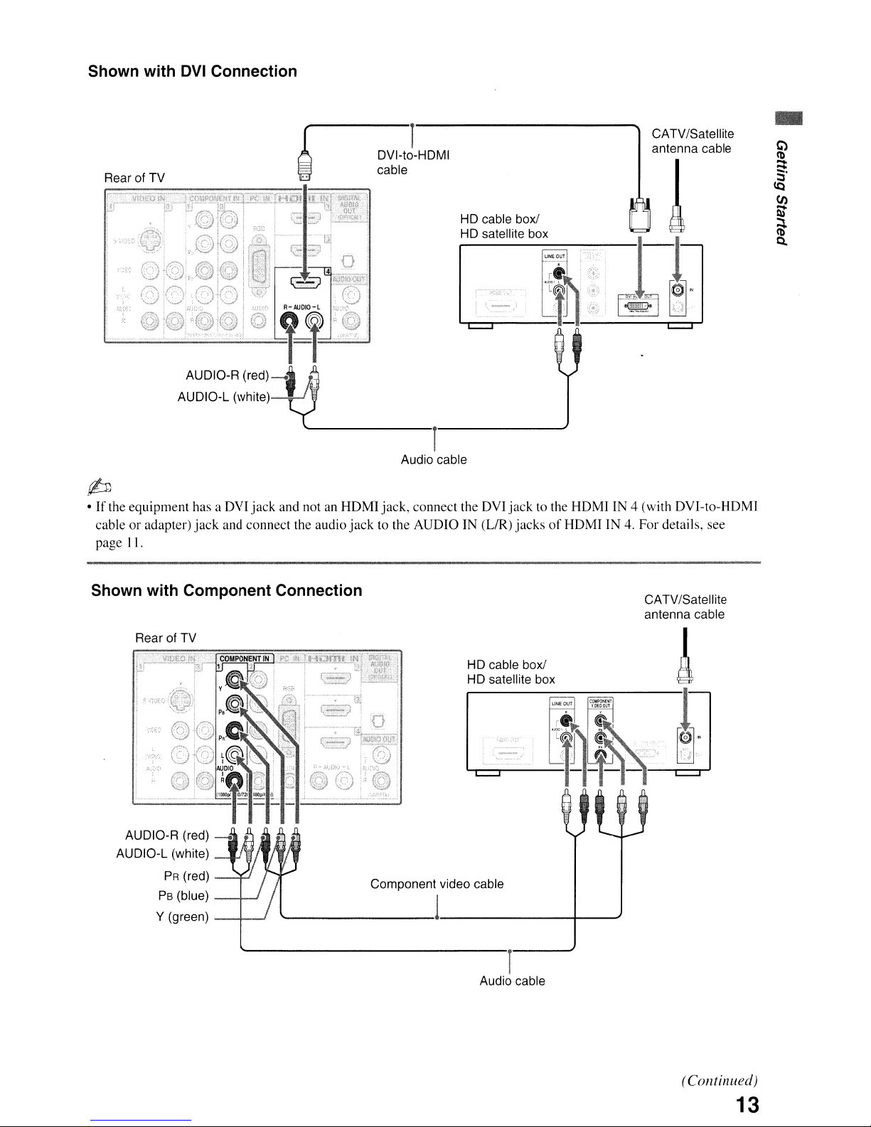
Shown with DVI Connection
Rear of TV
~
•Ifthe equipment has a OVI
jack
cable or adapter)
II.
page
and connect the audio jack to the AUDIO IN
1
DVI-to-HDMI
cable
HD cable box!
HD satellite box
CATV/Satellite
antenna cable
r
Audio cable
jack
and notanHDMI jack, connect the DVI jack to the HOMI IN 4 (with OVI-to-HOMI
(UR)
jacksofHOMI IN4.For details, see
-
Shown with Component Connection
Rear of TV
AUDIO-R (red) _
AUDIO-L (white)
PR
(red)
PB
(blue) _-+-..J
Y (green)
--+---'
_______
HD cable box!
HD satellite box
Component video cable
1
Audio cable
CATV/Satellite
antenna cable
!
-B-1]
--+_--'
r
(Continued)
13
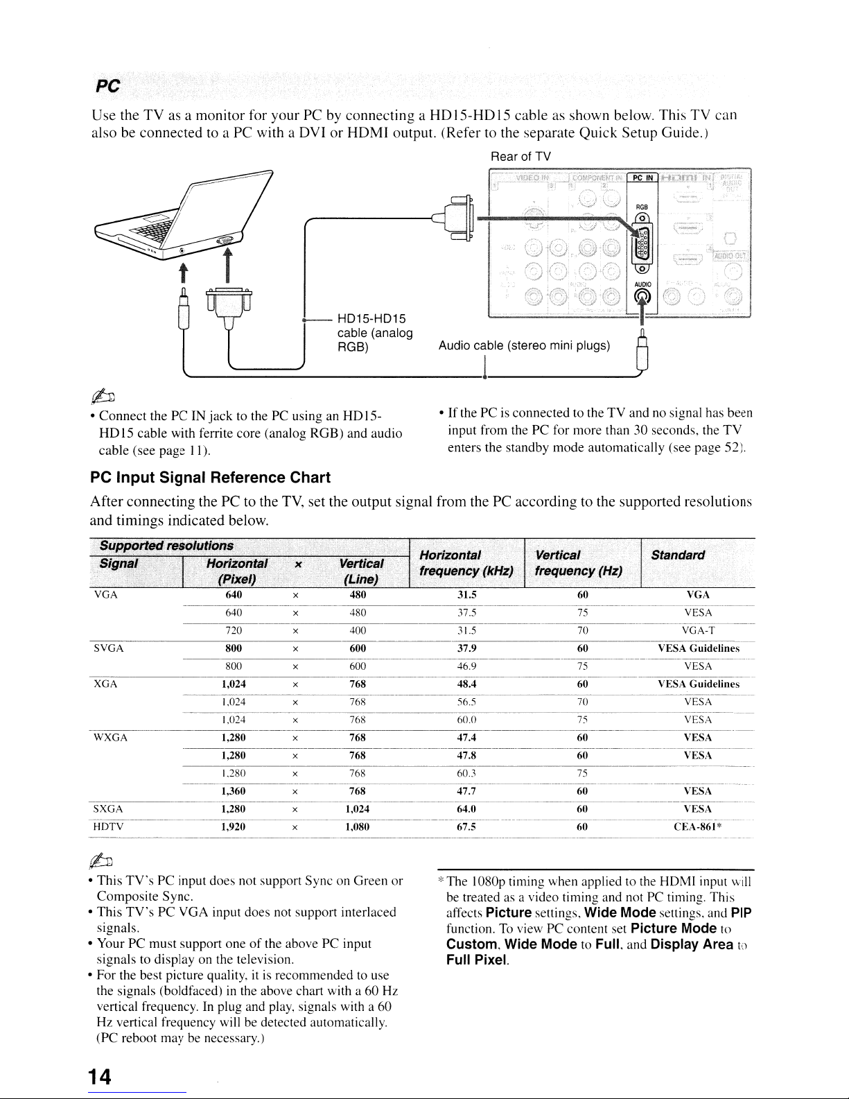
PC
Use the
also
TV
as a monitor for your PC by connecting a
be
connected to a PC with a DVI or HDMI output. (Refer to the separate Quick Setup Guide.)
_ HD15-HD15
cable (analog
RGB)
L----===:::::::::...
{b
• Connect the PC IN
HD15cable with ferrite core (analog RGB) and audio
cable (see page
PC Input Signal Reference Chart
After connecting thePCto the
and timings indicated below.
Il).
jack
to the PC using an HD15-
TV,
set the output signal from the PC according to the supported resolutions
HD
JS-HD
Audio cable (stereo mini plugs)
•Ifthe PCisconnected to theTVand no signal has been
input from the PC for more than 30 seconds. the
enters the standby
IS
cable as shown below. This TV can
Rear of TV
,l
mode
---'
automatically (see page 52).
TV
,t!~
x
x
x
SVGA
XGA
WXGA
{b
• This
TV's
PC input does not support Sync on Green or
Composite Sync.
TV's
• This
signals.
• Your PC must support one
signals to display on the television.
• For the best picture quality.
the signals (boldfaced)
vertical frequency. In plug and play, signals with a 60
Hz vertical frequency will
(PC reboot may be necessary.)
PC VGA input does not support interlaced
of
the above PC input
itisrecommended to use
in
the above chart with a 60 Hz
be
detected automatically.
Standard
VGA
VESA
VGA-T
31.5
Vertical
fre
'Y
(Hz)
60
75
70
*The 1080p timing when applied to the HDMI input will
be
treated as a video timing and not PC timing. This
affects Picture settings, Wide Mode settings. and PIP
function.Toview PC content set Picture Mode to
Custom, Wide Mode to Full. and Display Area to
Full Pixel.
14
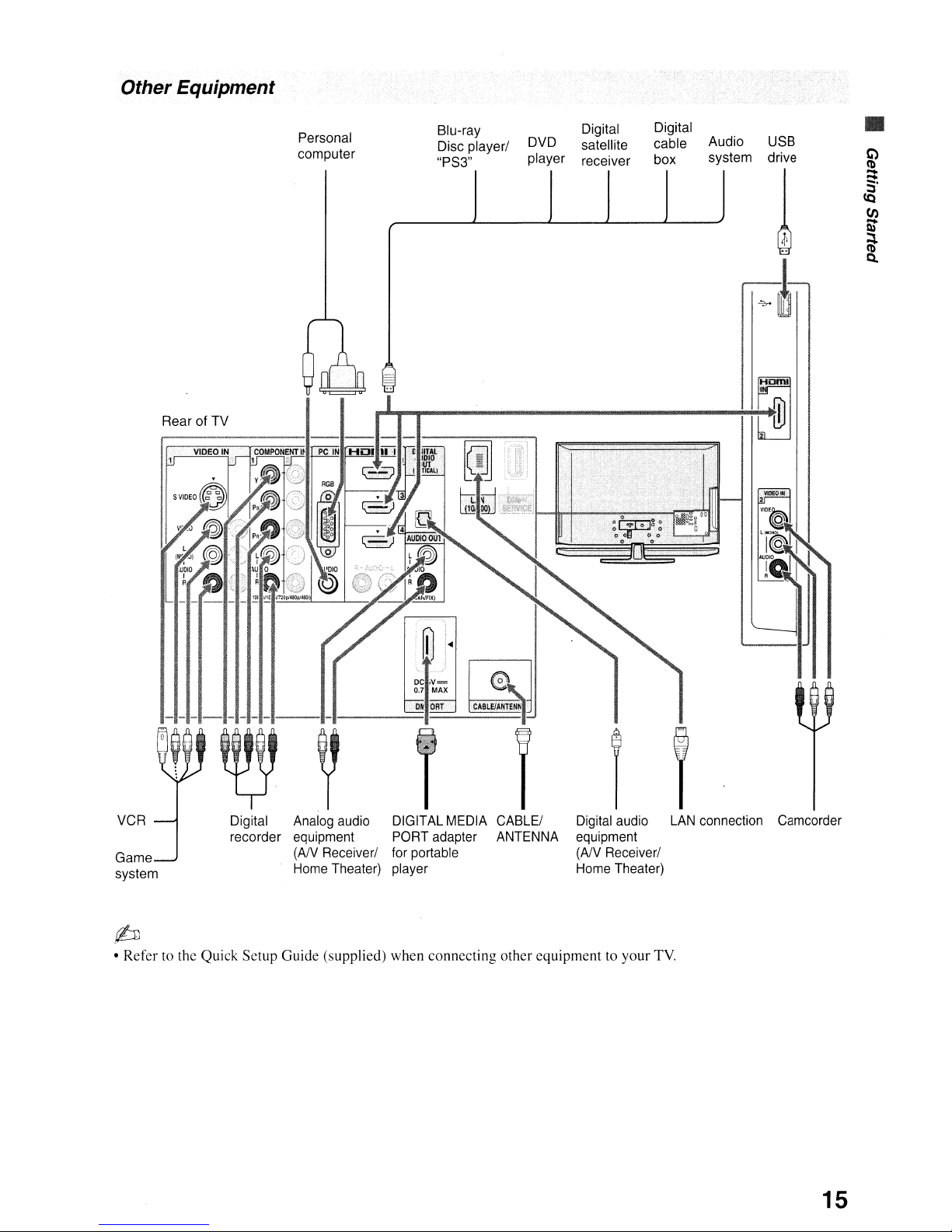
Other Equipment
Rear of TV
Personal
computer
Blu-ray
Disc player/
"PS3"
DVD
player
Digital
satellite
receiver
Digital
cable
box
Audio USB
system drive
•
VCR
Game
system
Digital
recorder
Analog audio
equipment
(AN
Home Theater)
{b
• Refertothe Quick Setup Guide (supplied) when connecting other equipmenttoyour
Receiver/
DIGITALMEDIA CABLE/
PORT adapter ANTENNA
for portable
player
Digital audio
equipment
(NV
Receiver/
Home Theater)
LAN
connection Camcorder
TV.
15
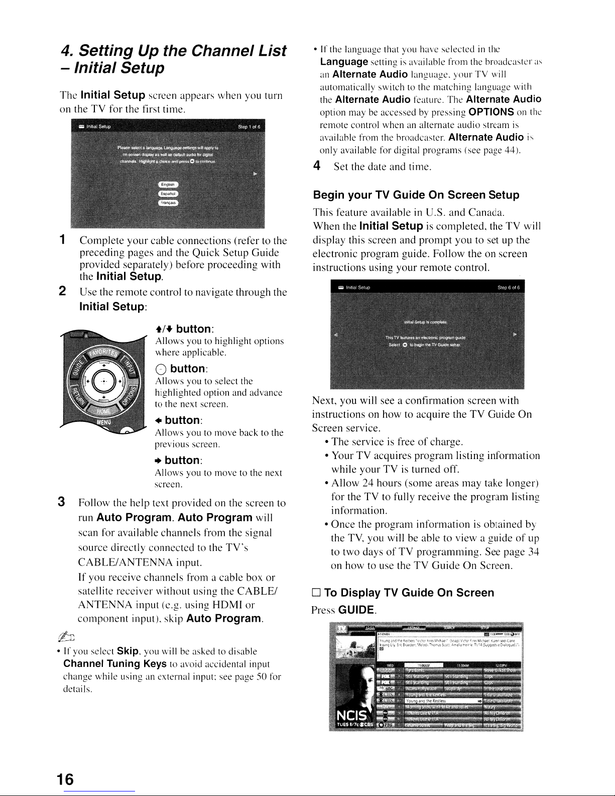
4.
Setting Up the Channel List
- Initial Setup
The
Initial Setup screen appears when you turn
on the
1
2 Use the remote control to navigate through the
3 Follow the help text provided on the screen to
TV
for the first time.
Complete
your
cable connections (refer to the
preceding pages and the Quick Setup Guide
provided separately) before proceeding with
Initial Setup.
the
Initial Setup:
+/+ button:
Allows
where
()
Allows
highlighted
to the next screen.
• button:
Allows
previous
youtohighlight
applicable.
button:
you to select the
option
youtomove
screen.
and
back
options
advance
to the
+ button:
Allows
screen.
run Auto Program. Auto Program
scan for available channels from the signal
source directly connected to the
CABLE/ANTENNA
If
you receive channels from a cable box
satellite receiver without using the
ANTENNA
component
input (e.g. using
input), skip Auto Program.
you to
input.
move
TV's
HOMI
to the next
will
or
CABLE/
or
•Ifthe language that you have
Language setting
an Alternate Audio language.
automatically
the
Alternate Audio feature.
option may be
remote
availahle from the broadcaster. Alternate Audio is
only
control
available for digital
is
available from the
switch to the
accessedbypressing
when
an alternate
selectedinthe
yourTVwill
matching
The
audio
programs
broadcaster
language
Alternate Audio
OPTIONS on the
stream
(see page 44).
with
is
4 Set the date and time.
Begin your TV Guide On Screen Setup
This feature availableinU.S. and Canada.
When
the Initial Setupiscompleted, the TV will
display this screen and
electronic program guide. Follow the on screen
instructions using your remote control.
Next, you will see a confirmation screen with
instructions on how to acquire the
Screen service.
•
The
service is freeofcharge.
• Your TV acquires program listing information
while your
TVisturned off.
• Allow 24 hours (some areas
TV
for the
to fully receive the program listing
information.
•
Once
the program information is obtained by
the TV, you will be able to view a guide
to two days
of
on how to use the
o
To
Display TV Guide On Screen
Press GUIDE.
prompt
you to set up the
TV
Guide
may
take longer)
of
TV programming. See page 34
TV
Guide
On
Screen.
as
On
up
~
• If
you
select Skip, you will be asked to disable
Channel Tuning Keys to avoid accidental input
change
details.
16
while using an
external
input: see page50for
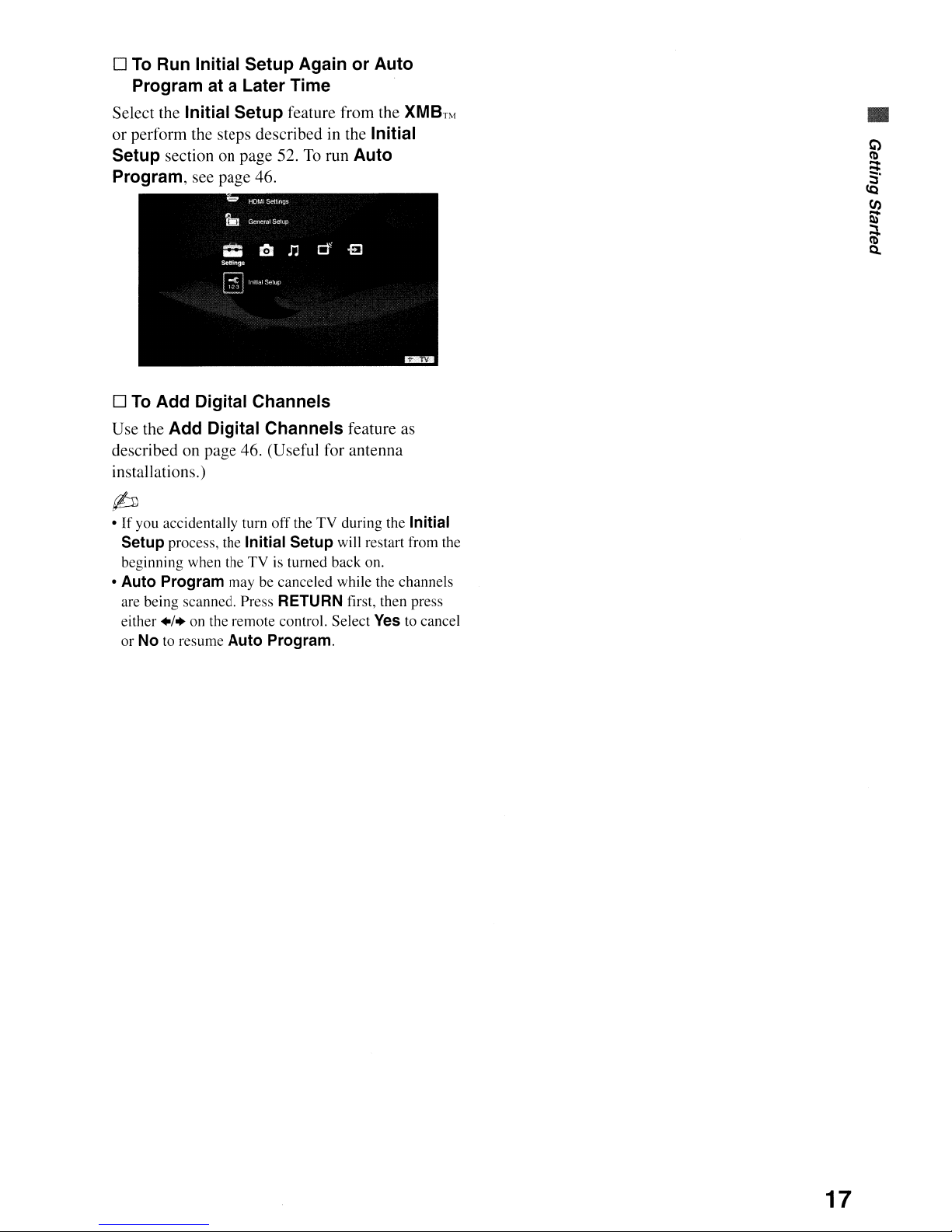
o
To
Run Initial Setup Again or Auto
Program at a Later Time
Select the Initial Setup feature from the
or perform the steps described in the Initial
Setup
Program,
o
Use the Add Digital Channels feature as
described on page 46. (Useful for antenna
installations.)
section on page 52.Torun Auto
see page 46.
To
Add Digital Channels
XMBnf
~
•Ifyou accidentally turn
Setup process, the Initial Setup will restart from the
beginning when the
• Auto Program may be canceled while the channels
are being scanned. Press
+/.
either
or
No to resume Auto Program.
on the remote control. Select
off
the TV during the Initial
TVisturned back on.
RETURN first, then press
Yes
to cancel
•
17
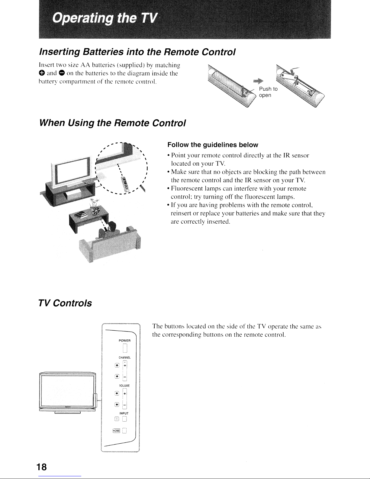
Inserting Batteries into the Remote Control
Insert
two
size
AA
o
and.
battery
batteries
on the batteries to the
compartmentofthe
(supplied)
diagram
remote
by matching
inside the
control.
When Using the Remote Control
Follow the guidelines below
,
,
,
" \
"
..
__
,
\
,,<
...
,
• Point
•
•
•
your
remote
locatedonyour
Make
sure thatnoobjects
the
remote
Fluorescent
control: try
If
you are having
reinsertorreplace
are
correctly
control
lamps
turning
inserted.
control directly at theIRsensor
TV.
and theJRsensoronyour
can
off
problems
your
...
are
interfere
the
fluorescent
with the
batteries
Push to
open
blocking
with
remote
and
the path
your
lamps.
make
between
TV.
remote
control,
sure that
they
TV Controls
POWER
o
CHANNEL
1-1
0+!
[±J
-I
'-J
VOLUME
:d
INPUT
00
18
The buttons locatedonthe sideofthe
the cOITesponding
buttons
on the
remote
TV
control.
operate
the
same
as
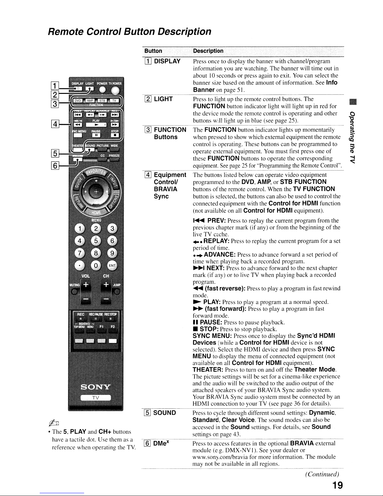
Remote Control Button Description
fib
• The 5, PLAY and CH+ buttons
have a tactile dot. Use them as a
reference when operating the
TV.
Button
[]
DISPLAY
[g]
LIGHT
~
FUNCTION
Buttons
@]
Equipment
Controll
BRAVIA
Sync
lID
SOUND
Description
Press once to display the banner with channel/program
red for
of
SYNC
of
the
module
in
of
information you are watching. The banner will time out
about10secondsorpress again to exit. You
of
banner size based on the amount
Banner
Press to light up the remote control buttons. The
FUNCTION button indicator light will light up
the device mode the remote control is operating and other
buttons will light up
The FUNCTION button indicator lights up momentarily
when pressed to show which external equipment the remote
control is operating. These buttons can be programmed to
operate external equipment.
these FUNCTION buttons to operate the corresponding
equipment. See page
The buttons listed below can operate video equipment
programmed to the
buttonsofthe remote control. When the TV FUNCTION
button is selected, the buttons can also be used to control the
connected equipment with the
(not available on all
~
previous chapter mark (if any)
live TV cache.
...
period
...
time when playing back a recorded program.
~
mark (if any) or to live
program.
.....
mode.
~
~
forward mode.
II
• STOP: Press to stop playback.
SYNC MENU: Press once to display the Sync'd HDMI
Devices
selected). Select the HDMI device and then press
MENU
available on all
THEATER: Press to turn on and
The picture settings will be set for a cinema-like experience
and the audio will be switched to the audio output
attached speakers
Your BRAVIA Sync audio system must be connected by an
HDMI connection to your TV (see page 36 for details).
Press to cycle through different sound settings:
Standard, Clear Voice.
accessed
settings on page 43.
Press to access features
module (e.g.
www.sony.com/bravia for more information.
may not be available
on page 51.
in
blue (see page 25).
25
for
"Programming the Remote Control".
DVD,
AMP,
Control for HDMI equipment).
PREV: Press to replay the current program from the
REPLAY: Press to replay the current program for a set
of
time .
ADVANCE: Press to advance forward a set period
NEXT: Press to advance forward to the next chapter
TV
when playing back a recorded
(fast reverse): Press to
PLAY: Press to
(fast forward): Press to
PAUSE: Press to pause playback .
(while a Control for HDMI deviceisnot
to display the menuofconnected equipment (not
in
the Sound settings. For details, see Sound
playa
program at a normal speed.
Control for HDMI equipment).
of
your BRAVIA Sync audio system.
The sound modes can also be
in
the optional BRAVIA external
DMX-NVI).
See your dealer
in
all regions.
information. See Info
You
must first press one
or STB FUNCTION
Control for HDMI function
or
from the beginningofthe
playa
programinfast rewind
playa
off
can
select the
in
programinfast
the Theater Mode.
Dynamic,
or
The
•
(Continued)
19
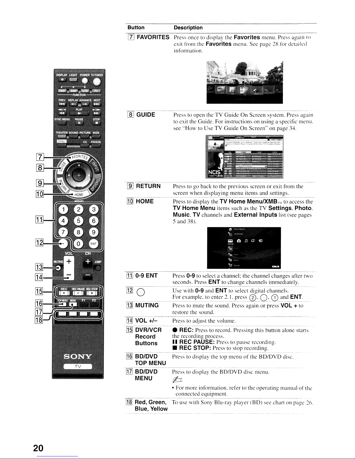
Button Description
[l]
FAVORITES Press once to display the Favorites menu. Press again to
[ID
RETURN
[Q]
HOME
exit from the
information.
to
Press
to exit the Guide. For instructions on using a specific menu.
see "How to UseTVGuide On Screen" on page 34.
Press to go back to the previous screen or exit from the
screen when displaying menu items and settings.
Press to display the
TV Home Menu items such as theTVSettings, Photo.
Music, TV
5 and 38).
Favorites menu. See page
open theTVGuideOnScreen system. Press again
TV Home Menu/XMBr"
channels and External Inputs list (see pages
28
for detailed
to
access the
[li] 0-9 ENT
[12]0
[j]] MUTING
[j]
VOL~
~rrn~DVRNCR--.
Record the recording process.
Buttons
-1J]]-B-D-jDvD~----
TOP MENU
ffZlB-D/DVD-~~Pres~~-display
MENU b
-[~rRed,
Green,--To
Blue, Yellow
0-9 to select a channel; the channel changes after two
Press
seconds. Press
Use with
For example,
Press to mute the sound. Press again or press
restore the sound.
Presstoadjust the
REC:
II
REC PAUSE: Press to pause recording .
• REC STOP: Press to stop recording.
P~~~~st~-di
• For more information. refer to the operating manualofthe
connected equipment.
use-;ithS~ny
ENT to change channels immediately.
0-9 and ENT to select digital channels.
to
enter 2.1, press
volume.~-------·----·---·~·~---~
Pr~~-t;-
spl~y-t~top
rec~-;:-d~
~~~~L~f
the
SD/OVO-
Blu-ray
0,
Pr~~~~g
the
dis~~;;e~~.
p-laY~~(BD)~ee~hart~l~p~gc-26.
O·
G)
and
ENT.
VOL
+ to
this-butto~~~-;;~;:t~rts
-BD;DVDd~~~
------
20
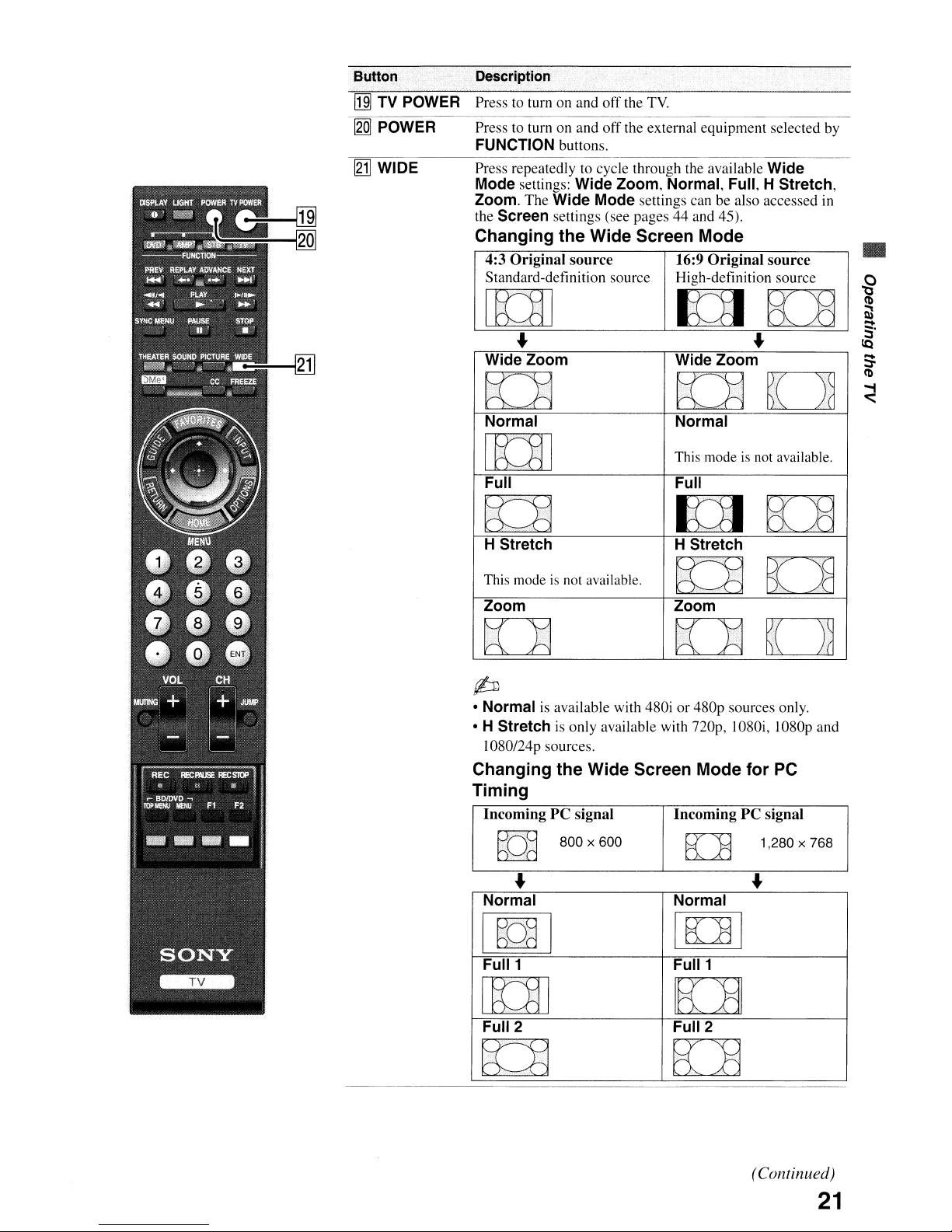
Button
[j]
TV
POWER
I2:Q]
POWER Press to turn on and
~WIDE
Description
Press to turn on and
FUNCTION buttons.
Press repeatedly to cycle through the available Wide
settings: Wide Zoom, Normal, Full, H Stretch,
Mode
Zoom.
the
Changing the Wide Screen Mode
The Wide Mode settings can be also accessed in
Screen settings (see pages
4:3 Original source
Standard-definition source High-definition source
off
the
TV.
off
the external equipment selected
44
and 45).
16:9
Original source
by
•
1m
Wide Zoom
D
Normal
[[lTI
Full
~
.•.
····i,
~
H Stretch
This modeisnot available.
Zoom
D
(bJ
• Normal is available with 480i
• H Stretch is only available with
I080124p sources.
Changing the Wide Screen Mode for PC
Timing
IncomingPCsignal IncomingPCsignal
Wide Zoom
DO
Normal
This modeisnot available.
Full
KlI
H Stretch
~D
Zoom
DO
or
480p sources only.
nop,
ED8
B:J8
1080i, 1080p and
hO~
Normal Normal
I
~Qd
Full 1
800 x 600
I
[[]]
Full 2 Full 2
~
K:J3
I
EL:H
Full 1
K1]
B:8
1,280 x 768
I
(Continued)
21
Button Description
~
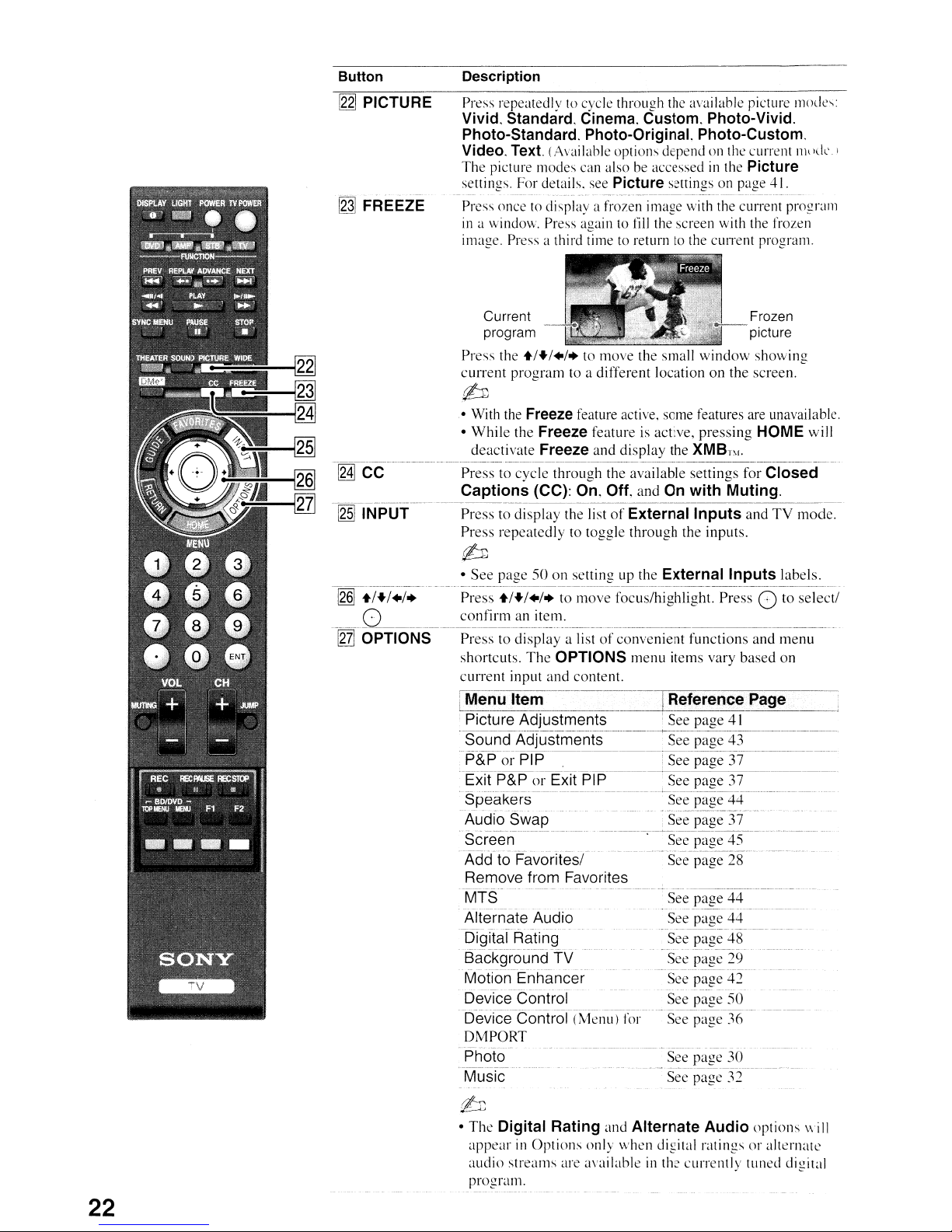
PICTURE
~
FREEZE
Press repeatedly
Vivid.
Standard.
Photo-Standard.
Video.
Text. (Available options dependonthe current
The picture modes can alsobeaccessedinthe
settings. For details. see
--
---
--------
Press oncetodisplay a frozen image with the current
in
a window. Press againtofill
image. Press a third time
Current Frozen
program picture
Press the
+/./+/+
to
cycle through the available picture
Cinema.
Photo-Original.
Custom.
Photo-Vivid.
Photo-Custom.
Picture
Picture
-------_._----~-_._,
settingsonpage 41.
..
_----_._------------_
the screen with the frozen
to
returntothe
CUITent
program.
to move the small window showing
mode'..:
n1\
'ek ,
..
---
progr~111l
current program to a different location on the screen.
(6J
• With
the
• While the
-----_.
~
--_._._---_.----~-_._------~---------~-~------~-------------
CC
Press to cycle through the available settings for
Captions
-[g§]
Ir~.fpUT----
Press to display the listofExternal
Freeze
deactivate
feature active. some features are unavailable.
Freeze
Freeze
(CC):
featureisactive, pressing
and display the XMB
On.
Off. andOnwith
".
T
Muting.
Inputs
HOME
will
Closed
and TV mode.
Press repeatedly to toggle through the inputs.
(6J
• See page 50 on settingupthe
--_._,-_._-_.
__
-[g§]
-i
/./
.i.-
o
-lni-
OPTIONS---Pl~~~;;_t~dispi~y-;l~t-~;t:convenient
._._------------------~------~-_._._---------_.
Press
+/./+/+
confirm
shortcuts.
to move focus/highlight. Press 0 to select/
an
item.
The
OPTIONS
current input and content.
LMenu
·
·
-
-Exit
·
·Spe'akers------------------------T-
Item
Picture
Sound
P&PorPTP---~-~j
Adjustments
Adjustmenfs-----See
P&P
Audi()
Swap
Scree-n---------------
.
()rExitPIP
----
..
===l
---------·---Seepage
External
Inputs
functions and
labels.
m~nu
menu items vary based on
Reference
' See page
page
Page
41
43
See page 37
.See page 37
page44-
See
•
See-page
---------------
Ii-
45--------------
--
22
Adcft() FavorTfeS( - "See'-page28"
Remove
MTS-
-------------
Alternate
-I5TgltafRating·-Se-epage-4S-------
--
---
Background
- -
Motion
Device
-Device-ControT(Men-L~)T(;J:-·-Seepage
from
Favorites
--
- .-
Audio See page
----------
------
---
TV See page 29
- -
---
--
Enhancer
--
------------
----------
Control
----~--
"See"page
-_
..
_---------._--._------------
-----------------------
See page 42
See page
44--~------
44
50
36--
DMPORT
-Photo-
-Muslc-
See page 30
-
_._--------------------
See page
32
b
• The
Digital
appear
audio streams are available
program.
Rating
in
Options only when digital ratings or alternate
and
Alternate
in
Audio
the currently tuned digital
options will
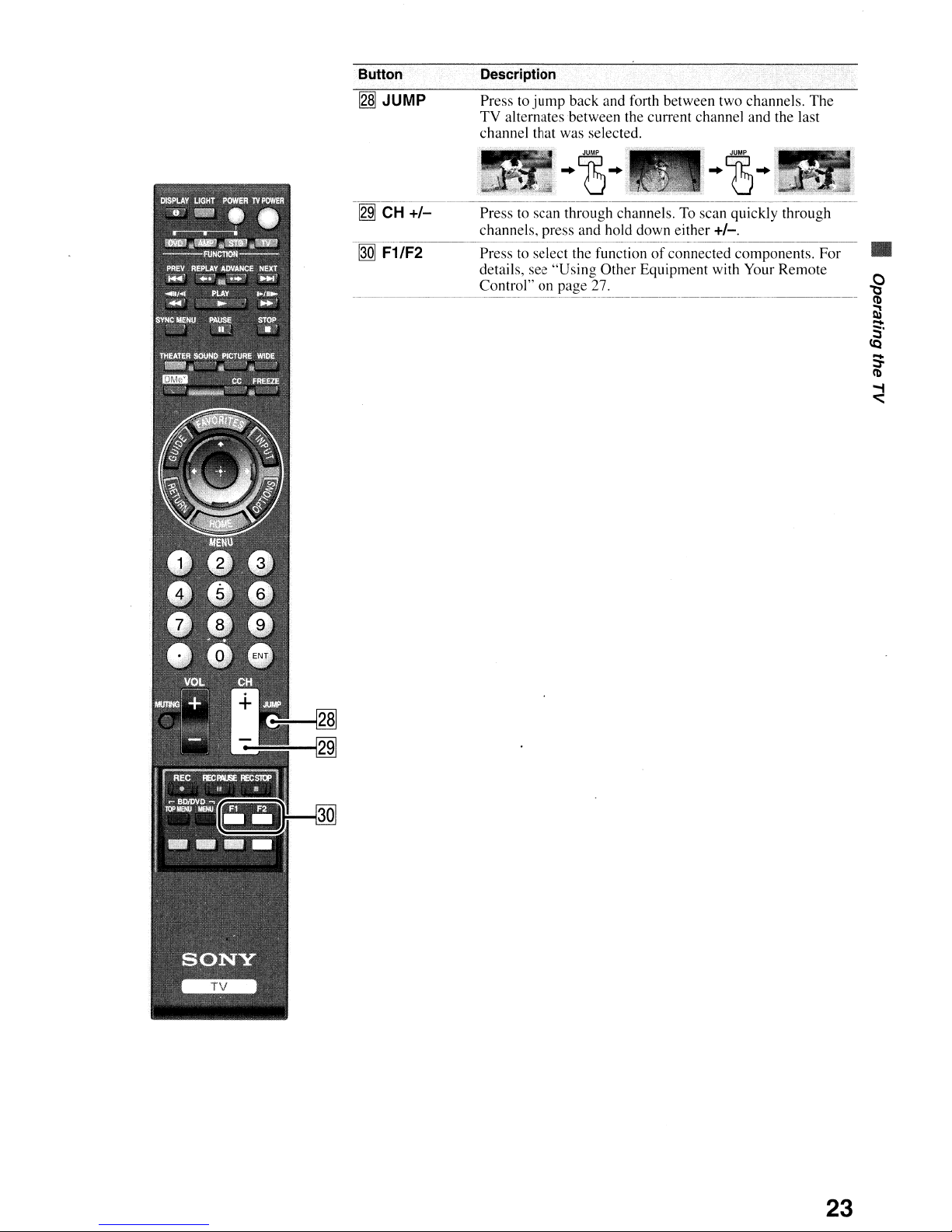
Button
~JUMP
Description
Press(0jump
TV alternates between the current channel and the last
channel that was selected.
back and forth between two channels. The
~
00
CH
+/-
F1/F2
Press to scan through channels.
channels. press and hold down either
Press to select the functionofconnected components. For
details, see "Using Other Equipment with Your Remote
Control" on page 27.
To
scan quickly through
+/-.
•
23
 Loading...