

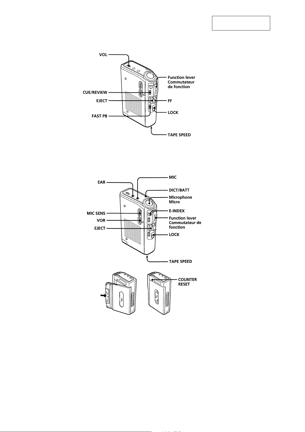
Sony BM-23 Mk2 Service manual
BM-23MK2
SERVICE MANUAL
Ver. 1.0 2005.08
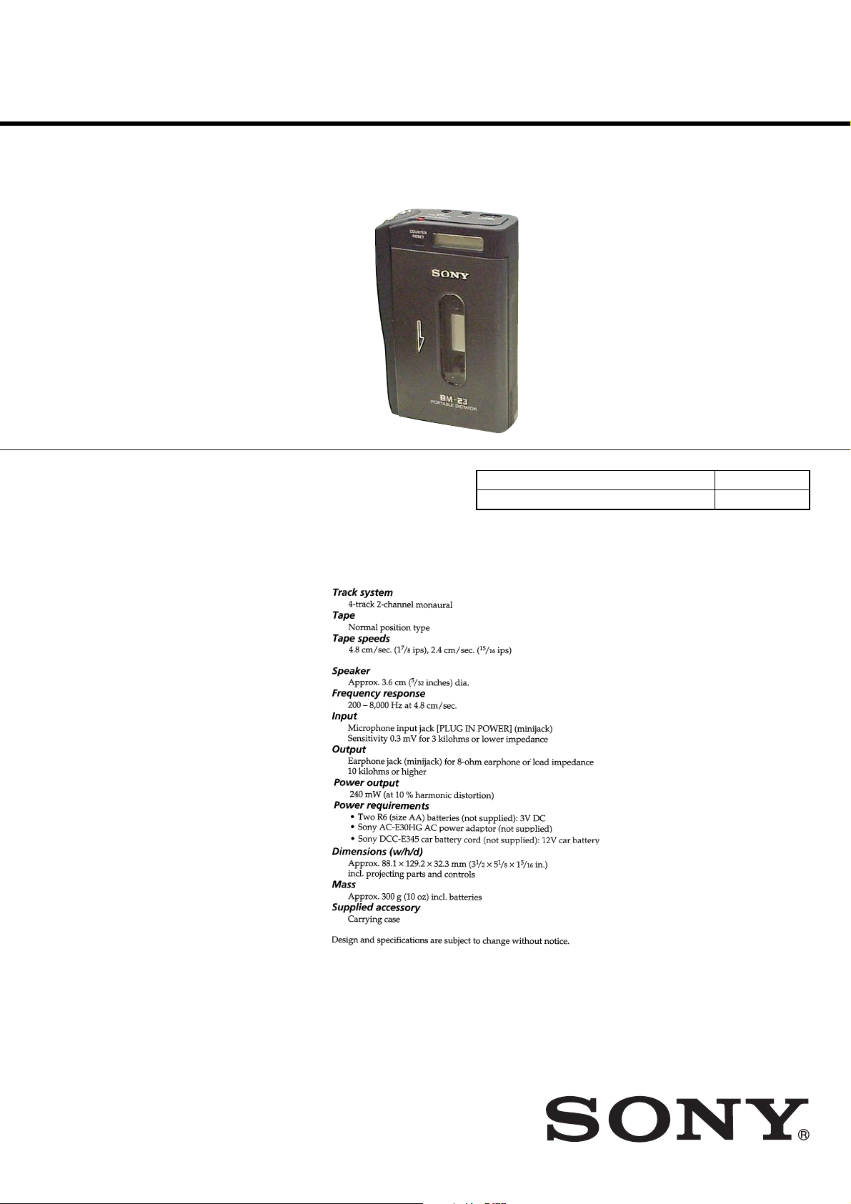
SPECIFICATIONS
US Model
Model Name Using Similar Mechanism NEW
Tape T ransport Mechanism T ype MB-23MK2-101
9-879-836-01
2005H1678-1
© 2005.08
PORTABLE DICTATOR
Sony Corporation
Personal Audio Group
Published by Sony Engineering Corporation

BM-23MK2
CAUTION
Use of controls or adjustments or performance of procedures
other than those specified herein may result in hazardous radiation
exposure.
Notes on chip component replacement
•Never reuse a disconnected chip component.
• Notice that the minus side of a tantalum capacitor may be
damaged by heat.
Flexible Circuit Board Repairing
•Keep the temperature of soldering iron around 270˚C during
repairing.
• Do not touch the soldering iron on the same conductor of the
circuit board (within 3 times).
• Be careful not to apply force on the conductor when soldering
or unsoldering.
UNLEADED SOLDER
Boards requiring use of unleaded solder are printed with the leadfree mark (LF) indicating the solder contains no lead.
(Caution: Some printed circuit boards may not come printed with
the lead free mark due to their particular size)
: LEAD FREE MARK
Unleaded solder has the following characteristics.
• Unleaded solder melts at a temperature about 40 °C higher
than ordinary solder.
Ordinary soldering irons can be used but the iron tip has to be
applied to the solder joint for a slightly longer time.
Soldering irons using a temperature regulator should be set to
about 350 °C.
Caution: The printed pattern (copper foil) may peel away if
the heated tip is applied for too long, so be careful!
• Strong viscosity
Unleaded solder is more viscou-s (sticky, less prone to flow)
than ordinary solder so use caution not to let solder bridges
occur such as on IC pins, etc.
• Usable with ordinary solder
It is best to use only unleaded solder but unleaded solder may
also be added to ordinary solder.
TABLE OF CONTENTS
1. SERVICING NOTES ............................................... 3
2. GENERAL ................................................................... 4
3. DISASSEMBLY
3-1. Disassembly Flow ........................................................... 5
3-2. Cabinet (Rear) Block Assembly ...................................... 6
3-3. Control Panel Block Assembly........................................ 7
3-4. AUDIO Board.................................................................. 8
3-5. Mechanism Deck (MB-23MK2-101) .............................. 9
3-6. Holder Panel Assembly ................................................... 9
4. MECHANICAL ADJUSTMENTS......................... 10
5. ELECTRICAL ADJUSTMENTS .......................... 10
6. DIAGRAMS
6-1. Block Diagram – AUDIO Section – ................................ 13
6-2. Printed Wiring Boards ..................................................... 14
6-3. Schematic Diagram – AUDIO Board (1/4) – .................. 15
6-4. Schematic Diagram – AUDIO Board (2/4) – .................. 16
6-5. Schematic Diagram – AUDIO Board (3/4) – .................. 17
6-6. Schematic Diagram – AUDIO Board (4/4) – .................. 18
6-7. Schematic Diagram – LCD Board –............................... 19
7. EXPLODED VIEWS
7-1. Cabinet Section................................................................ 22
7-2. Chassis Section ................................................................ 23
7-3. Mechanism Deck Section-1 (MB-23MK2-101).............. 24
7-4. Mechanism Deck Section-2 (MB-23MK2-101).............. 25
8. ELECTRICAL PARTS LIST .................................. 26
SAFETY-RELATED COMPONENT WARNING!!
COMPONENTS IDENTIFIED BY MARK 0 OR DOTTED LINE
WITH MARK 0 ON THE SCHEMATIC DIAGRAMS AND IN
THE PARTS LIST ARE CRITICAL TO SAFE OPERATION.
REPLACE THESE COMPONENTS WITH SONY PARTS WHOSE
PART NUMBERS APPEAR AS SHOWN IN THIS MANUAL OR
IN SUPPLEMENTS PUBLISHED BY SONY.
2
BM-23MK2
2
SECTION 1
SERVICING NOTES
This unit use PH501 (photo coupler) to detect reel rotation.
As PH501 is mounted on the AUDIO board, reel rotation will not be detected if the AUDIO board has been removed.
When performing mechanism deck operation and voltage checks whit the A UDIO board removed, perform them using the follo wing method.
Method:
Connect TP32 of the AUDIO board and GND with a jumper wire.
AUDIO BOARD (SIDE B)
TP3
PH501
IC503
3
BM-23MK2
SECTION 2
GENERAL
This section is extracted
from instruction manual.
4
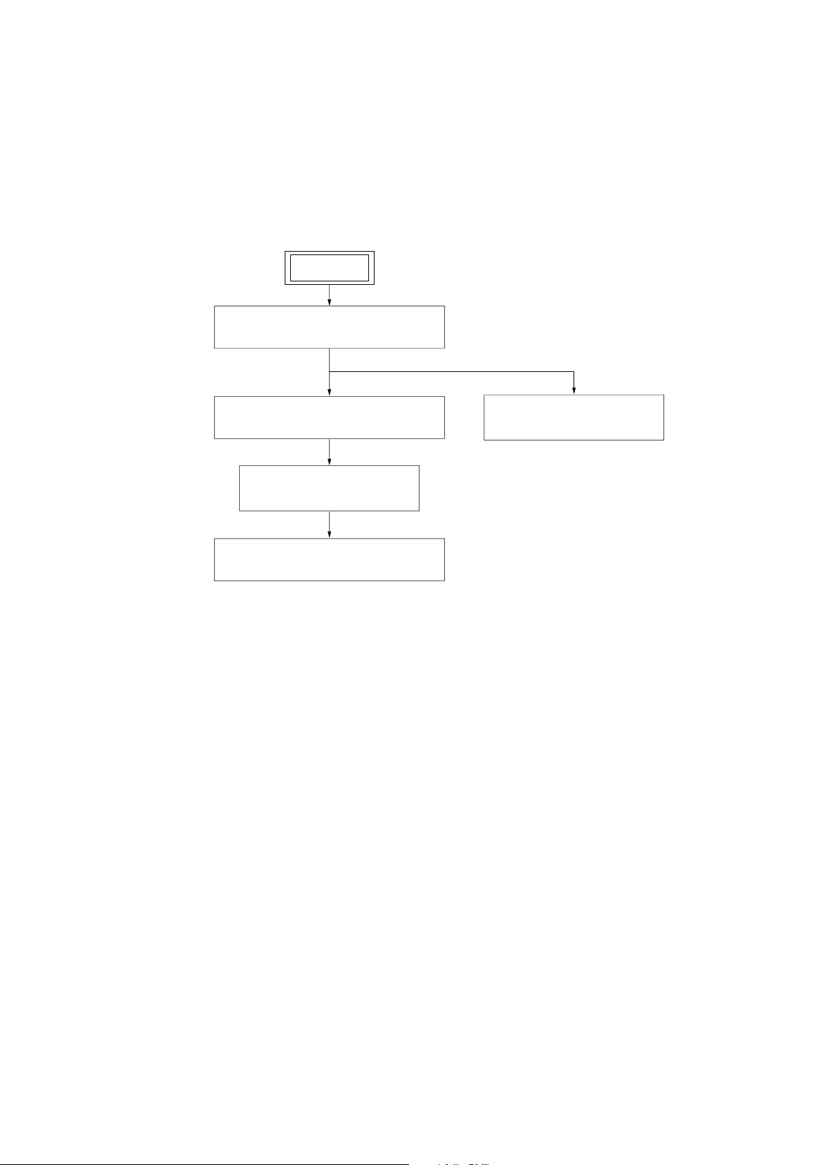
3-1. DISASSEMBLY FLOW
•This set can be disassembled in the order shown below.
SET
BM-23MK2
SECTION 3
DISASSEMBLY
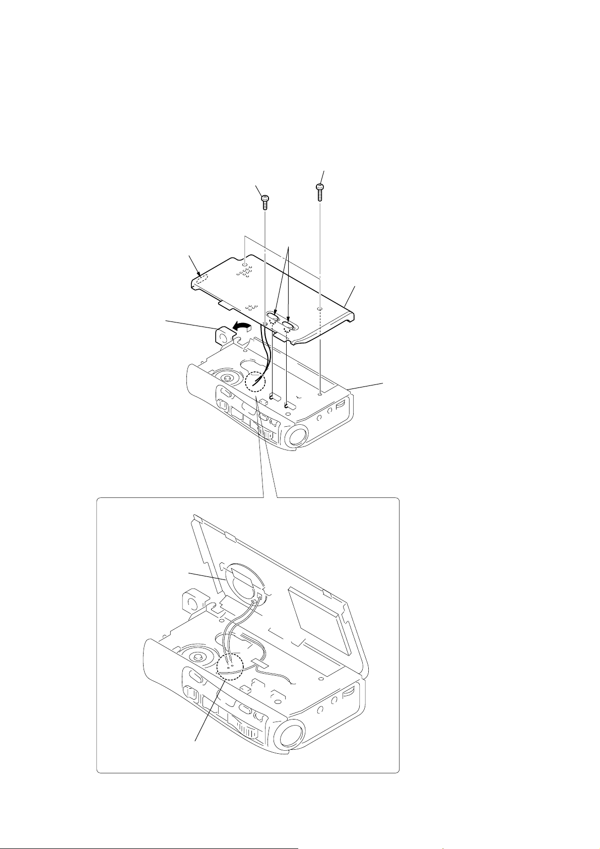
3-2. CABINET (REAR) BLOCK ASSEMBLY
(Page 6)
3-3. CONTROL PANEL BLOCK ASSEMBLY
(Page 7)
3-4. AUDIO BOARD
(Page 8)
3-5. MECHANISM DECK (MB-23MK2-101)
(Page 9)
3-6. HOLDER PANEL ASSEMBLY
(Page 9)
5
BM-23MK2
Note: Follow the disassembly procedure in the numerical order given.
3-2. CABINET (REAR) BLOCK ASSEMBLY
2
screw
(M 1.4
×
5.0)
3
two screws
(+BTP 1.7
×
10)
1
Open the battery case lid
in the direction of arrow.
A
A
5
cabinet (rear) block assembly
note : When attaching the cabinet (rear)
block assembly, adjust the position
of the three knobs indicated by
arrows
AUDIO board.
A
and the switch of the
AUDIO board
speaker
4
Remove soldering
two the four points.
6
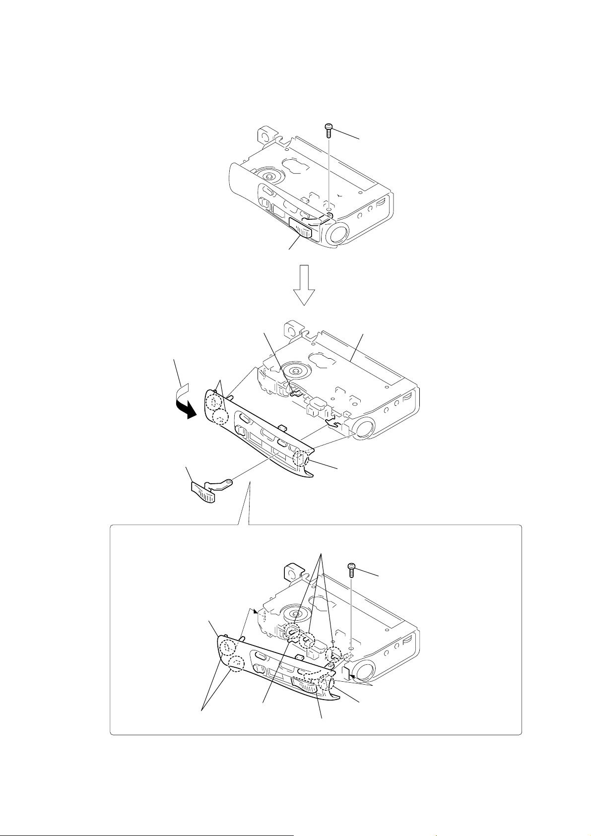
3-3. CONTROL PANEL BLOCK ASSEMBLY
control button assembly
1
screw (M1.4)
BM-23MK2
4
lever (lock)
6
Remove the control panel block
assembly in the direction of the arrow.
2
two claws
5
control button assembly
qd
control panel
block assembly
AUDIO board
3
claw
PRECAUTION DURING CONTROL PANEL BLOCK
ASSEMBLY INSTALLATION
8
To attach the control panel block
assembly , align the three switch positions as shown.
qs
screw (M1.4)
qa
two claws
9
lever (lock)
0
7
control button assembly
claw
7
BM-23MK2
)
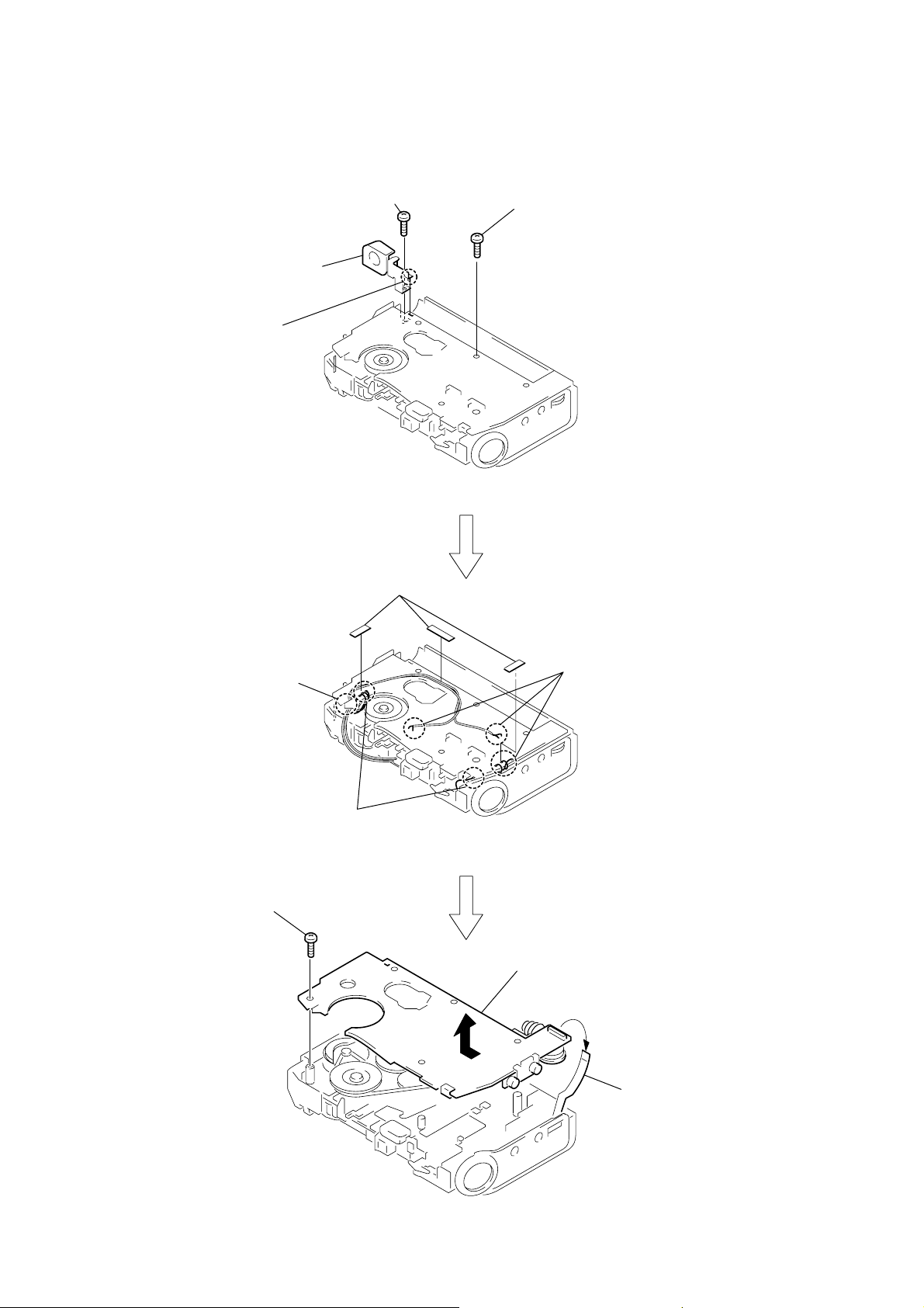
3-4. AUDIO BOARD
3
Remove the soldering.
4
battery case
2
screw (1.7 × 2.5)
1
screw (M1.4 × 3)
6
harnesses
7
from the five points.
0
screw (M1.4 × 3)
5
three cabinet
upper cushions
Remove soldering
8
Remove soldering
from the seven points.
qa
Remove the AUDIO board complete
in the direction of arrow.
9
flexible board
(CN101) (12core
8
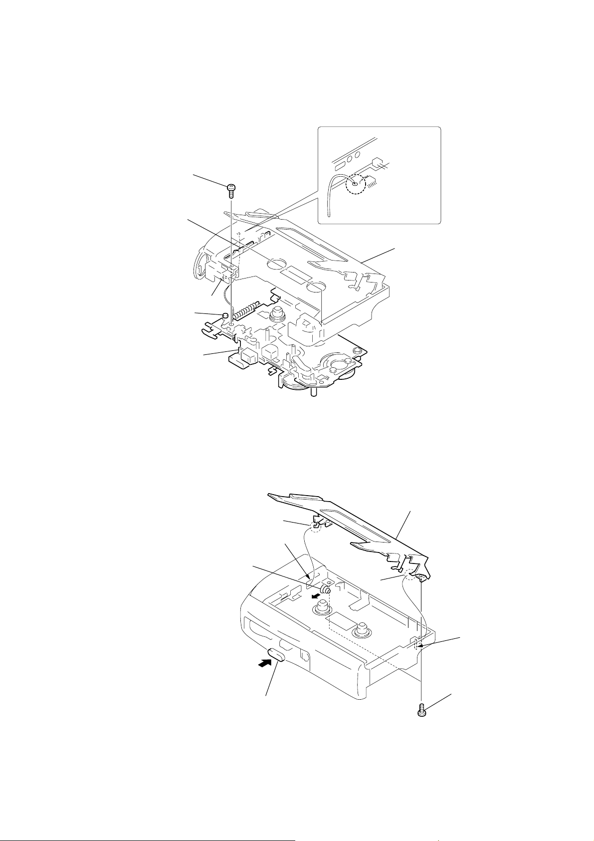
3-5. MECHANISM DECK (MB-23MK2-101)
t
3
two screws (M1.4 × 3.0)
lock plate assembly
A
shaft-A
1
Remove the soldering.
2
Set the holder panel
assembly to eject.
BM-23MK2
4
mechanism deck
(MB-23MK2-101)
3-6. HOLDER PANEL ASSEMBLY
2
Move the battery coil spring in the direction
of the arrow and secure it with the screw.
claw
A
note : When attaching the mechanism deck,
set the mechanism deck to stop and
adjust the position of shaft-A and par
A of the lock plate assembly.
4
holder panel assembly
claw
A
1
While pressing the button (eject), insert
the two claws of the holder panel assembly
into the holes indicated by arrows
A
.
3
two screws (M1.4 × 1.6)
9
BM-23MK2
SECTION 4
MECHANICAL ADJUSTMENTS
SECTION 5
ELECTRICAL ADJUSTMENTS
PRECAUTION
1. Clean the following parts with a denatured-alcohol-moistened
swab :
playback head rubber belts
capstan idlers
pinch roller
2. Demagnetize the playback head with a head demagnetizer.
3. Do not use a magnetized screwdriver for the adjustments.
4. The adjustments should be performed with the rated power
supply voltage (3V) unless otherwise noted.
•Torque Measurement
Mode Torque Meter Meter Reading
2.06 – 3.72 mN•m
FWD 21 – 38 g•cm
CQ-102C
FWD
Back Tension
REV 21 – 38 g•cm
CQ-102RC
REV
Back Tension
FF
CQ-201B
REW
(0.30 – 0.52 oz•inch)
0.05 – 0.29 mN•m
0.5 – 3 g•cm
(0.01 – 0.04 oz•inch)
2.06 – 3.72 mN•m
(0.30 – 0.52 oz•inch)
0.05 – 0.29 mN•m
0.5 – 3 g•cm
(0.01 – 0.04 oz•inch)
more than 60 g•cm
(more than 0.84 oz•inch)
PRECAUTION
1. Power supply voltage : 3V
Test T ape
Type Signal Used for
WS-48A 3 kHz, 0 db Tape Speed Adjustment
Tape Speed 4.8cm/s Adjustment
Switch position
TAPE SPEED Switch : 4.8 cm
Procedure:
test
WS-48A
(3 kHz, 0 dB)
18
set
J102
1. Play back WS-48A (tape center portion) in FWD mode.
Adjust the R V601 so that the frequenc y counter reads 2,980±
30 Hz.
2. Play back WS-48A (tape center portion) in REV mode.
Confirm that the reading of frequency counter is within 2.5 %
from the reading in step 1.
frequency
counter
Ω
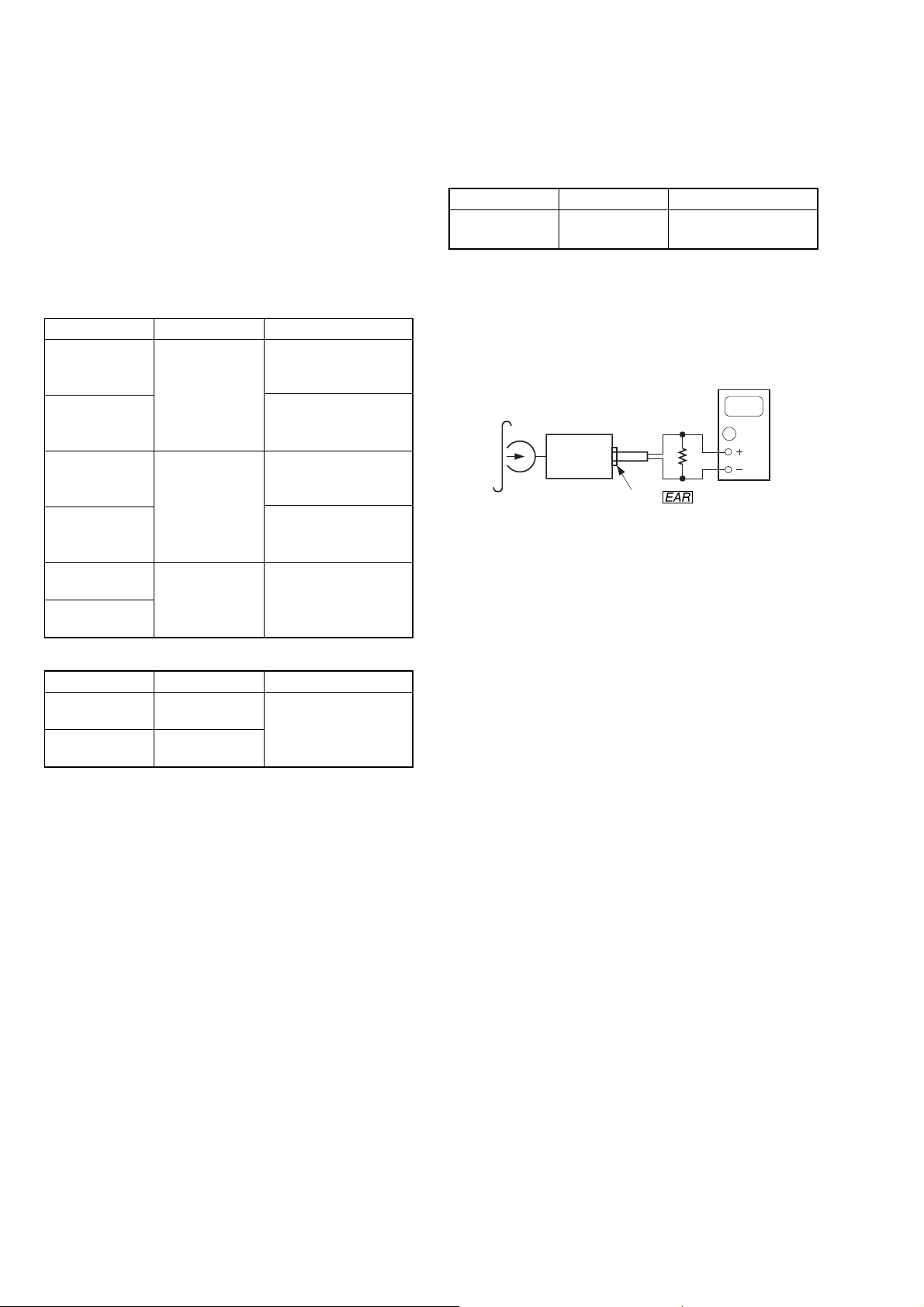
•Tape Pulling Force Measurement
Mode Torque Meter Meter Reading
FF CQ-403A
REW CQ-403R
(more than 1.42 oz)
more than 40 g
10
 Loading...