

Page 1

100BASE-T BOARD
BKSR-2070
INSTALLATION MANUAL
1st Edition
Page 2

! W ARNING
This manual is intended for qualified service personnel only.
To reduce the risk of electric shock, fire or injury, do not perform any servicing other than that
contained in the operating instructions unless you are qualified to do so. Refer all servicing to
qualified service personnel.
! W ARNUNG
Die Anleitung ist nur für qualifiziertes Fachpersonal bestimmt.
Alle Wartungsarbeiten dürfen nur von qualifiziertem Fachpersonal ausgeführt werden. Um die
Gefahr eines elektrischen Schlages, Feuergefahr und Verletzungen zu vermeiden, sind bei
Wartungsarbeiten strikt die Angaben in der Anleitung zu befolgen. Andere als die angegeben
Wartungsarbeiten dürfen nur von Personen ausgeführt werden, die eine spezielle Befähigung
dazu besitzen.
! A VERTISSEMENT
Ce manual est destiné uniquement aux personnes compétentes en charge de l’entretien. Afin
de réduire les risques de décharge électrique, d’incendie ou de blessure n’effectuer que les
réparations indiquées dans le mode d’emploi à moins d’être qualifié pour en effectuer d’autres.
Pour toute réparation faire appel à une personne compétente uniquement.
BKSR-2070
Page 3

Table of Contents
Manual Structure
Purpose of this manual ........................................................................................ 3 (E)
Contents ............................................................................................................... 3 (E)
Related manuals................................................................................................... 3 (E)
Trademark............................................................................................................ 3 (E)
1. Installation
1-1. Overview ...............................................................................................1-1 (E)
1-1-1. BKSR-2070 ..........................................................................1-1 (E)
1-2. Board Installation ..................................................................................1-2 (E)
1-3. Functions of Connectors .......................................................................1-4 (E)
1-4. Matching Connectors and Cables..........................................................1-4 (E)
2. Service Overview
2-1. Description of Internal Switches and Indicators ...................................2-1 (E)
2-1-1. CCM-38A Board (BKSR-2070) ..........................................2-1 (E)
2-2. Specifications ........................................................................................2-4 (E)
BKSR-2070
1 (E)
Page 4

Page 5

Purpose of this manual
Contents
Manual Structure
This manual is the installation manual of the BKSR-2070 100BASE-T ETHERNET
Board
.
This manual is intended for use by trained system and service engineers, and
describes the information regarding installation.
The following is a summary of all the section for understanding the contents of this
manual.
Section 1 Installation
Explains the overview of the BKSR-2070, how to install the BKSR-2070 to the
VSR-2000, and the connector and cable information for peripheral equipment
connections, etc.
Section 2 Service Overview
Explains the function and factory setting of the switches and LEDs on the board and
the specifications of the BKSR-2070.
Related manuals
Trademark
Besides this Installation Manual, the following manuals are available for the BKSR-
2070.
. VSR-2000/BKSR-2020/2031/2070/BKSH-209G
Service Manual (available on request)
This manual describes the information that premise the service based on parts
replacement (Version upgrading, diagnostics function, parts replacement, electrical adjustment, circuit outline, parts list, block diagrams).
If this manual is required, please contact your local Sony Sales Office/Service
Center.
. Ethernet is a registered trademark of XEROX corporation.
BKSR-2070
3 (E)
Page 6

Page 7

Section 1
Installation
1-1. Overview
1-1-1. BKSR-2070
The BKSR-2070 is the 100BASE-T Board that is attached on top of the SY-283 board of the VSR-2000.
The BKSR-2070 enables the transmisson and reception of the digital (MPEG2 coded) video and audio
data that are stored in the internal hard disk of the VSR-2000, to and from the external system through a
LAN (ETHERNET).
The BKSR-2070 consists of the following components.
. CCM-38A board (1)
. Installation Guide (1)
. Fixing screws (5)
BKSR-2070
1-1 (E)
Page 8
1-2. Board Installation
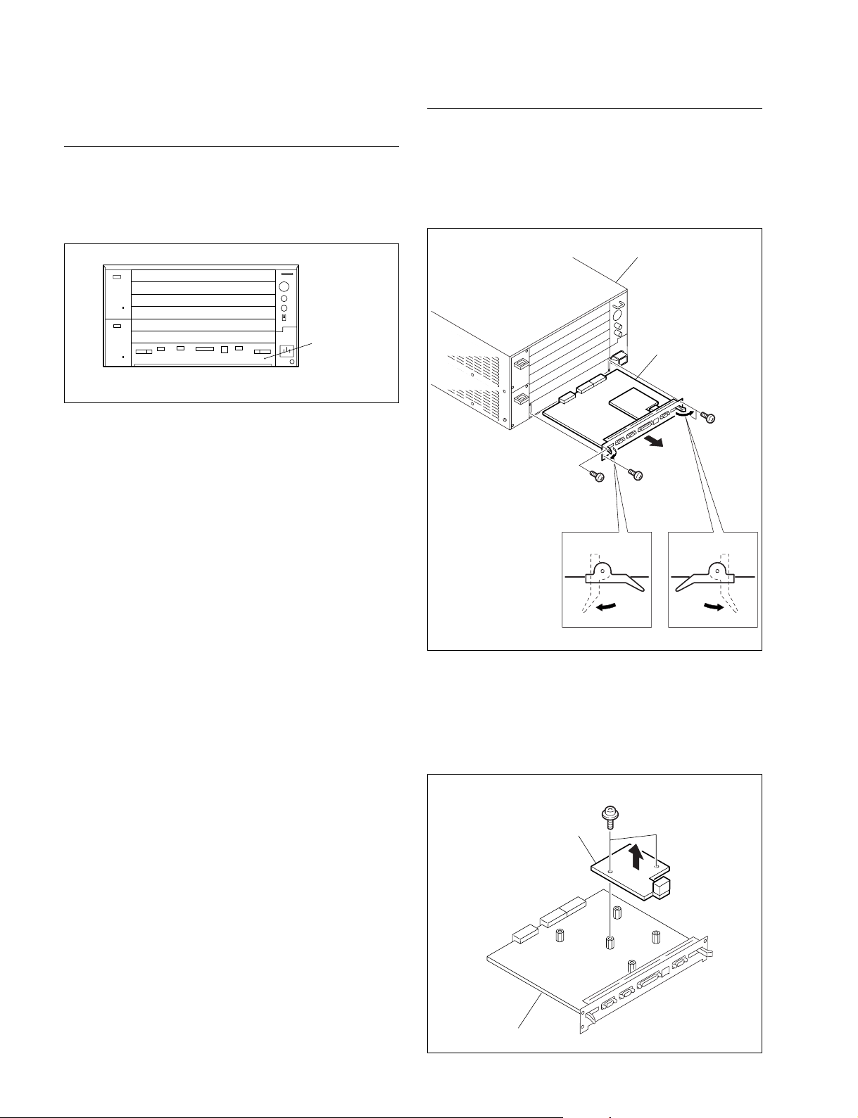
1-2. Board Installation
General information
. The BKSR-2070 is installed in place of the CCM-37
board that has been installed on top of the SY-283 board
which is inserted in No. 7 slot of the VSR-2000.
No.7 slot
VSR-2000 (rear side)
. No adjustment is needed after installing or replacing the
boards.
Procedure
1. Turn off the power switches A and B of the VSR-
2000.
2. Remove the four screws from the No. 7 slot and
remove the SY-283 board.
VSR-2000
SY-283 board
BVTT3 x 6
BVTT3 x 6BVTT3 x 6
Board lever Board lever
1
1
3. Remove the two screws and remove the CCM-37
board.
n
Store the removed CCM-37 board and screws in a safe
location.
PSW3 x 6
CCM-37 board
1-2 (E)
SY-283 baord
BKSR-2070
Page 9
1-2. Board Installation
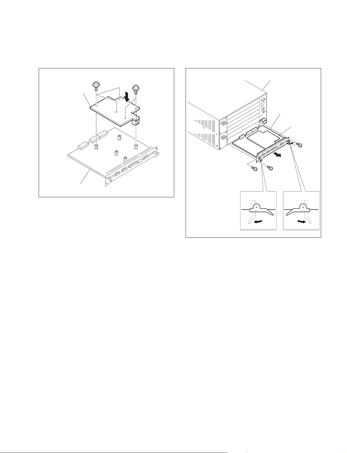
4. Attach the BKSR-2070 (CCM-38A board) on top of
the SY-283 board with the five screws that are supplied with the BKSR-2070.
PSW3 x 6
CCM-38A board
SY-283 board
PSW3 x 6
5. Insert the SY-283 board into the slot No. 7 and
connect it to the board securely by pressing the board
level in the direction of the arrow 1.
VSR-2000
SY-283 board
CCM-38A board
BVTT3 x 6
BVTT3 x 6BVTT3 x 6
Board lever Board lever
1
1
6. Fix the SY-283 board securely as before using the four
screws that have been used to fix the SY-283 board.
n
To remove the plug-in board, remove the desired by to the
front by pressing the board level in the direction of the
arrow 2.
BKSR-2070
1-3 (E)
Page 10
1-3. Functions of Connectors
1-4. Matching Connectors and Cables
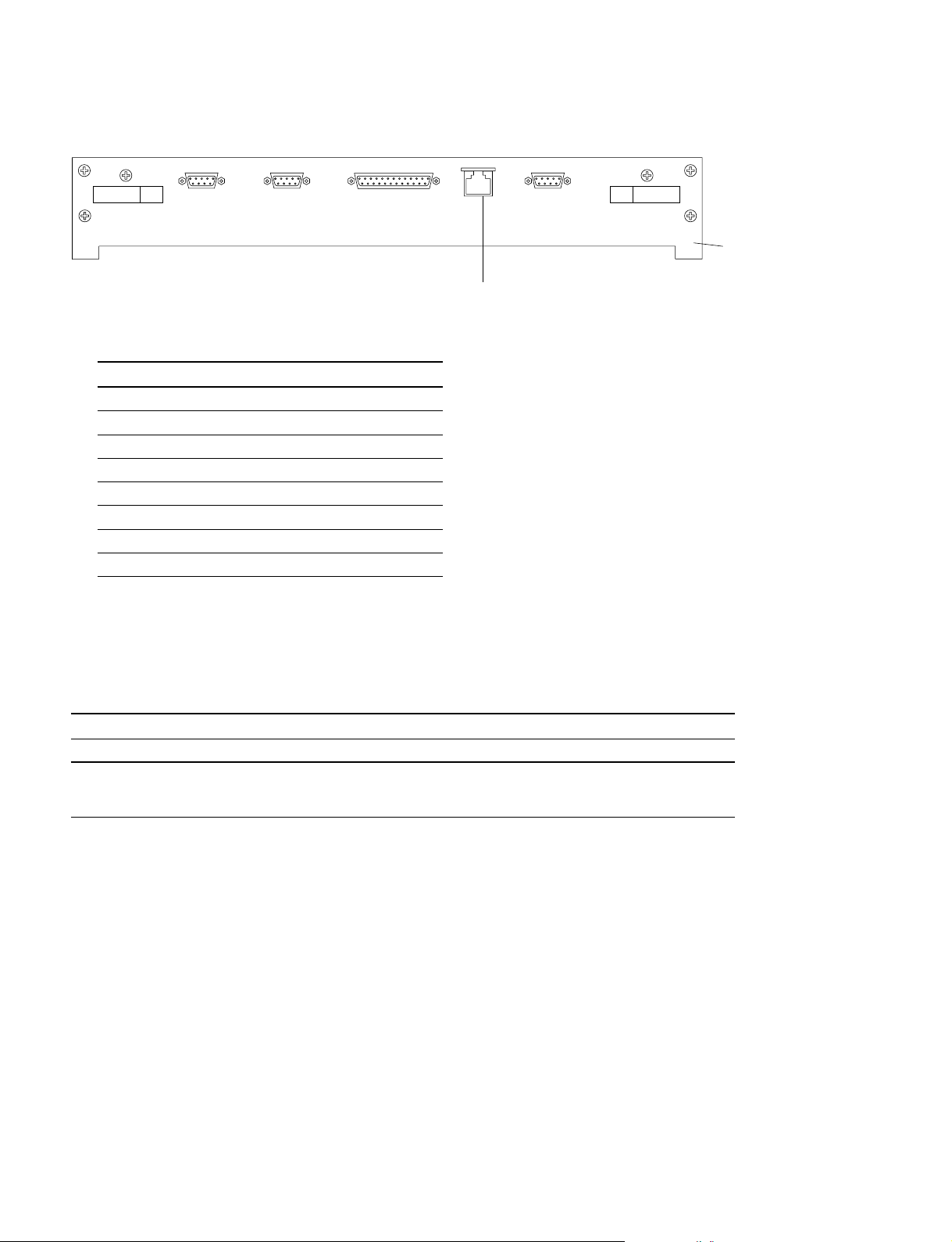
1-3. Functions of Connectors
ETHER
1
1 100BASE-T ETHERNET IF terminal : 8-pin modular connector
Connected to the network modular hub of a LAN (10/100BASE-T ETHERNET).
Pin No. Signal Name
1TX+
2TX_
3RX+
4NC
5NC
6RX_
7NC
8NC
Connector panel of
SY-283 board
1-4. Matching Connectors and Cables
When connecting cables to various connectors on the connector panel at the time of installation or
servicing, connect the following connectors/cables or their equivalents.
Connector on BKSR-2070 Matching Connector/Cable
Panel indication Connector Connector/Cable Sony Part No.
ETHER ETHERNET ETHERNET ––––––
STP category 5 STP category 5
cable
1-4 (E)
BKSR-2070
Page 11
Section 2
1ON2 3 4 5 6 7 8
Service Overview
2-1. Description of Internal Switches and Indicators
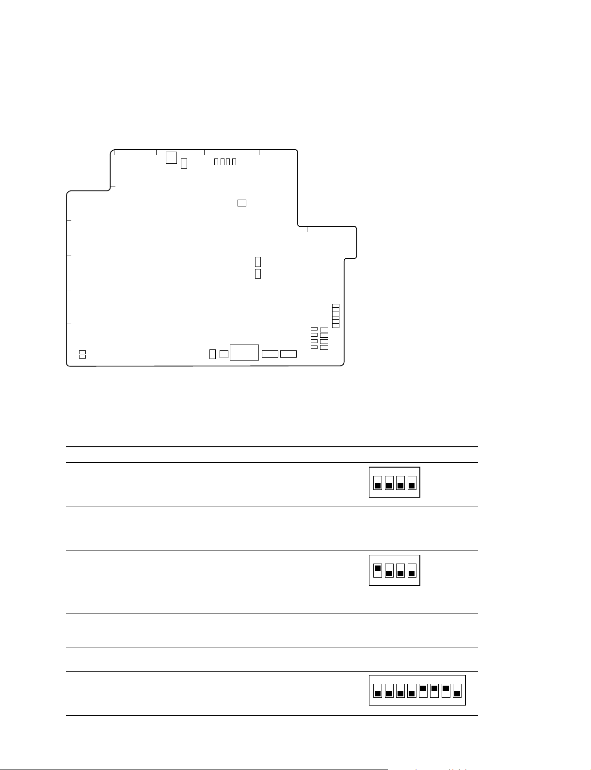
2-1-1. CCM-38A Board (BKSR-2070)
BCDE
1
CN204
S201
D552
D551
D554
D553
A
2
3
S1
F
S101
4
S102
D101
D104
D103
D102
D257
D258
D259
D260
D261
D262
S156
S155
S154
S153
Side A (Component side)
5
6
D106
D105
S51
S52
ND201
S151
S152
Switches
n
Do not change the setting of the switches described as “Factory use only”.
Ref. No. Address Name Description Factory Setting
S1 (D-2) Optional operation Factory use only
setting switch 1
1ON2 3 4
S51 (D-6) JTAG circuit selector CPU: CPU is included PLD position
S52 (D-6) JTAG condition switch B1 : Input signal selector to
S101 (D-4) CPU clock frequency Source oscillator of CPU is HI position
S102 (D-4) CPU clock frequency LO position
S151 (E-6) Optional operation Factory use only
BKSR-2070
switch in the circuit. (Never change)
PLD : CPU is not included
in the circuit.
CPU from the JTAG
circuit TRST signal
ON : JTAG DISABLE
OFF : JTAG ENABLE
1ON2 3 4
(Never change)
B2-4 : Not used
setting switch 1 selected by the combination (Never change)
of S101 and S102.
setting switch 2 (Never change)
setting switch 2
2-1 (E)
Page 12
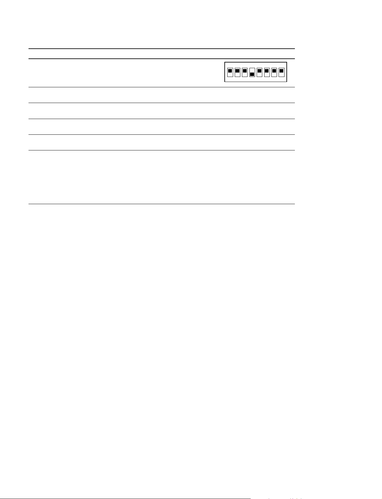
1ON2 3 4 5 6 7 8
2-1. Description of Internal Switches and Indicators
Ref. No. Address Name Description Factory Setting
S152 (E-6) Optional operation Software option
setting switch 3
S153 (F-6) POWER ON reset Initialization of board
switch
S154 (F-6) HRESET interrupt Generates the HRESET
switch interrupt.
S155 (F-6) SRESET interrupt Generates the SRESET
switch interrupt.
S156 (F-6) NMI interrupt switch Generates the NMI interrupt.
(ABORT)
S201 (C-1) RS-232C selector Selects the target connector of EXT position
switch console to which the RS-232C
is connected.
INT: Output to the internal
connector CN204.
EXT: Output to the 9-pin
connector on the
front panel of the console.
2-2 (E)
BKSR-2070
Page 13

2-1. Description of Internal Switches and Indicators
LED
Ref.No. Address Color Name Description Normal State
D101 (F-6) Green NMI interrupt Turns on when the NMI interrupt Turned off.
D102 (F-6) Green POWER ON reset Turns on when the POWER ON Turned off.
D103 (F-6) Green HRESET interrupt Turns on when the HRESET Turned off.
D104 (F-6) Green SRESET interrupt Turns on when the SRESET Turned off.
D105 (A-6) Green PROGRAM1 Turns on by the program. Changes depending on
D106 (A-6) Green PROGRAM2 Turns on by the program. Changes depending on
D257 (F-5) Green RECEIVE Turns on when data from the Changes depending on
D258 (F-5) Green TRANSMIT Turns on when data is Changes depending on
D259 (F-5) Green LINK Turns on when a link is Turns on at all times
D260 (F-5) Orange COLLISION Turns on when a collision Changes depending of
D261 (F-5) Green SPEED Turns on when a network (speed) Changes depending
D262 (F-5) Green DUPLEX MODE Turns on when a network is Changes depending
D551 (D-1) Green D+3.3 V power Turns on when the +3.3 V digital Turned on.
D552 (D-1) Green A+3.3 V power Turns on when the +3.3 V analog Turned on.
D553 (D-1) Green D+5.0 V power Turns on when the +5.0 V digital Turned on.
D554 (D-1) Green A+5.0 V power Turns on when the +5.0 V analog Turned on.
ND201 (D-6) 7 PROGRAM Displays the two digit number that Changes depending on
segment indicator is supplied from program. operation.
indicator is issued.
(When the switch is pressed or
turned on by the program.)
indicator resetis issued.
(When the switch is pressed
or turned on by the program.)
indicator interrupt is issued.
(When the switch is pressed
or turned on by the program.)
indicator interrupt is issued.
(When the switch is pressed
or turned on by the program.)
indicator (Specifications are not operation.
determined.)
indicator (Specifications are not operation.
determined.)
indicator network is received. operation. (Flashing)
indicator sent to network. operation. (Flashing)
indicator established with network. when the connector is
connected and the
power is turned on.
(Tuned on or off.)
indicator occurs in a network. a network.
(Flashing)
indicator is 100BASE-T. on the conditions of
a network.
(Turned off or flashing)
indicator full duplex mode. on the conditions of
a network.
(Turned off or flashing)
supply indicator power is supplied to the board.
supply indicator power is supplied to the board.
supply indicator power is supplied to the board.
supply indicator power is supplied to the board.
BKSR-2070
2-3 (E)
Page 14

2-2. Specifications
2-2. Specifications
BKSR-2070
General
Operating temperature 0 dC to 45 dC (32 dF to 113dF)
Storage temperature _20 dC to +60 dC (_4 dF to +140 dF)
Operating humidity 20 to 85% (without condensation)
Storage humidity 20 to 95% (without condensation)
Maximum external dimensions 216 x 156 x 20 mm (w/d/h)
(8 1/2 x 6 1/8 x 13/16 inches)
Mass Approx. 0.2 kg (7 oz)
Current consumption 1.5 A or less
Design and specifications are subject to change without prior notice.
2-4 (E)
BKSR-2070
Page 15

The material contained in this manual consists of
information that is the property of Sony Corporation and
is intended solely for use by the purchasers of the
equipment described in this manual.
Sony Corporation expressly prohibits the duplication of
any portion of this manual or the use thereof for any
purpose other than the operation or maintenance of the
equipment described in this manual without the express
written permission of Sony Corporation.
Le matériel contenu dans ce manuel consiste en
informations qui sont la propriété de Sony Corporation et
sont destinées exclusivement à l’usage des acquéreurs
de l’équipement décrit dans ce manuel.
Sony Corporation interdit formellement la copie de
quelque partie que ce soit de ce manuel ou son emploi
pour tout autre but que des opérations ou entretiens de
l’équipement à moins d’une permission écrite de Sony
Corporation.
Das in dieser Anleitung enthaltene Material besteht aus
Informationen, die Eigentum der Sony Corporation sind,
und ausschließlich zum Gebrauch durch den Käufer der
in dieser Anleitung beschriebenen Ausrüstung bestimmt
sind.
Die Sony Corporation untersagt ausdrücklich die
Vervielfältigung jeglicher Teile dieser Anleitung oder den
Gebrauch derselben für irgendeinen anderen Zweck als
die Bedienung oder Wartung der in dieser Anleitung
beschriebenen Ausrüstung ohne ausdrückliche
schriftliche Erlaubnis der Sony Corporation.
BKSR-2070
Page 16

BKSR-2070 (SY) J, E
3-203-496-01
Printed in Japan
Sony Corporation 1999. 10 16
Broadcasting & Professional Systems Company ©1999
 Loading...