

Page 1

Network Management Adaptor BKM-FW32
2-560-787-02 (1)
Network
Management
Adaptor
取扱説明書
Operating Instructions
Mode d’emploi
Bedienungsanleitung
Manual de instrucciones
Istruzioni per l’uso
お買い上げいただきありがとうございます。
電気製品は安全のための注意事項を守らないと、火
災や人身事故になることがあります。
この取扱説明書には、事故を防ぐための重要な注意事項と製品の
取り扱いかたを示してあります。この取扱説明書をよくお読みの
うえ、製品を安全にお使いください。お読みになったあとは、い
つでも見られるところに必ず保管してください。
JP
GB
FR
DE
ES
IT
CS
BKM-FW32
2004 Sony Corporation
Page 2
安全のために
ソニーの製品は安全に充分配慮して設計されています。し
かし、電気製品は、まちがった使いかたをすると、火災や
感電などにより死亡や大けがなど人身事故につながること
があり、危険です。
事故を防ぐために次のことを必ずお守りください。
安全のための注意事項を守る
4(JP)ページの注意事項をよくお読みください。
定期点検をする
5年に1度は、内部の点検を、お買い上げ店またはソニー
のサービス窓口にご依頼ください(有料)。
故障したら使わない
すぐに、お買い上げ店またはソニーのサービス窓口にご連
絡ください。
万一、異常が起きたら
・煙が出たら
・異常な音、においが
したら
・内部に水、異物が
入ったら
・製品を落としたり
キャビネットを破損
したときは
1 ディスプレイの電 源を
b
切る。
2 ディスプレイの電 源
コードや接続コードを
抜く。
3 お買い上げ店または
ソニーのサービス窓
口に連絡する。
警告表示の意味
取扱説明書および製品で
は、次のような表示をして
います。表示の内容をよ
く理 解し て か ら 本 文を お
読みください。
この表 示の注 意事項を守
らないと、健 康 を 害 す る
おそれがあります。
この表 示の注 意事項を守
らないと、感 電 や その 他
の事故によりけがをしたり
周辺の物品に損害を与え
たりすることがあります 。
注意を促す記号
行為を禁止する記号
行為を指示する記号
この装置は、情報処理装置等電波障害自主規制協議会
(VCCI)の基準に基づくクラスB 情報技術装置です。この 装
置は、家庭環境で使用することを目的としていますが、この
装置がラジオやテレビジョン受信機に近接して使用されると、
受信障害を引き起こすことがあります。取扱説明書に従って
正しい 取り扱 いをしてください 。
JP
2
Page 3

目次
注意 ..................................................
使用上のご注意 .....................................
このマ ニュアルについて ........................
各部の名称と働き ..................................
ネットワーク機 能を使う
準備をする...................................
本機を取り付ける ................................... 7(JP)
システム構成 .......................................... 8(JP)
コンピューターで操作する...................
ディスプレイをコントロ ールする............................
トラブル時の対処 ................................
仕様 ....................................................
4 (JP)
5 (JP)
5 (JP)
6 (JP)
7 (JP)
10 (JP)
10(JP)
13 (JP)
14 (JP)
JP
JP
3
Page 4
下記の注意を守らないと、けがをしたり周辺の物品に損害
を与えることがあります。
取り付けは専門の工事業者に依頼する
お客様が取り付けを行うと、火災や感電により人身事故につながります。
取り付けにつ い て は 、必ずお買い上げ店またはソニーのサービス窓口にご依
頼ください。
接続の際は電源を切る
電源コードや接続ケーブルを接続するときは、電源を切ってください。感電や
故障の原因となることがあります。
お手入れの際は、電源を切って電源プラグを抜く
電源を接続したままお手入れをすると、感電の原因となることがあります。
内部を開けない、改造しない
内部には電圧の高い部分があり、キャビネットや裏ぶたを開けたり改造したり
すると、火災や感電の原因となることがあります。内部の調整や設定、点検、
修理はお買い上げ店またはソニーのサービス窓口にご依頼ください。
コネクター部には、手を触れない
ディスプレイ内部 のコネクター部には手を触れないでください 。
けがをしたり故障の原因となることがあります。
基板の取り付けは注意深く
この説明書で説明しているアダプター(拡張ボード)をフラットパ ネ ル ディスプ
レイのスロットに 取り付けるときは、部品や基板などの角で、手や指にけがをし
ないように注意深く作業してください。
JP
注意
4
Page 5

使用上のご注意
このマニュアル
• 本機のソフトウェア の 仕 様は、改良のため
予告なく変更することがありますが、ご了
承ください。
• アプリケーションソフトウェアは、この取扱
説明書の画面と一部異なる場合がありま
す。
• 安全の為に該当ポートに は 過 電圧が加わ
る恐れのないネットワークに接 続し てくださ
い。
について
このマ ニュアルでは、FlatPanel Display
FWDシリーズに本機を取り付け、ネットワー
クを 介し てご 使 用に なる場合の操作につい
て説明しています。
◆ディスプレイの通 常 の操作については、
FWDシリーズの取扱説明書をご覧くださ
い。
...........................................................................................................................................................................
MicrosoftおよびWindowsは、米国 MicrosoftCorporationの米国およびその他の国における登録
•
商標です。
その他記載された商品名、会社名などは、各社の商標または登録商標です。
•
使用上のご注意/このマニュアルについて
JP
5
Page 6
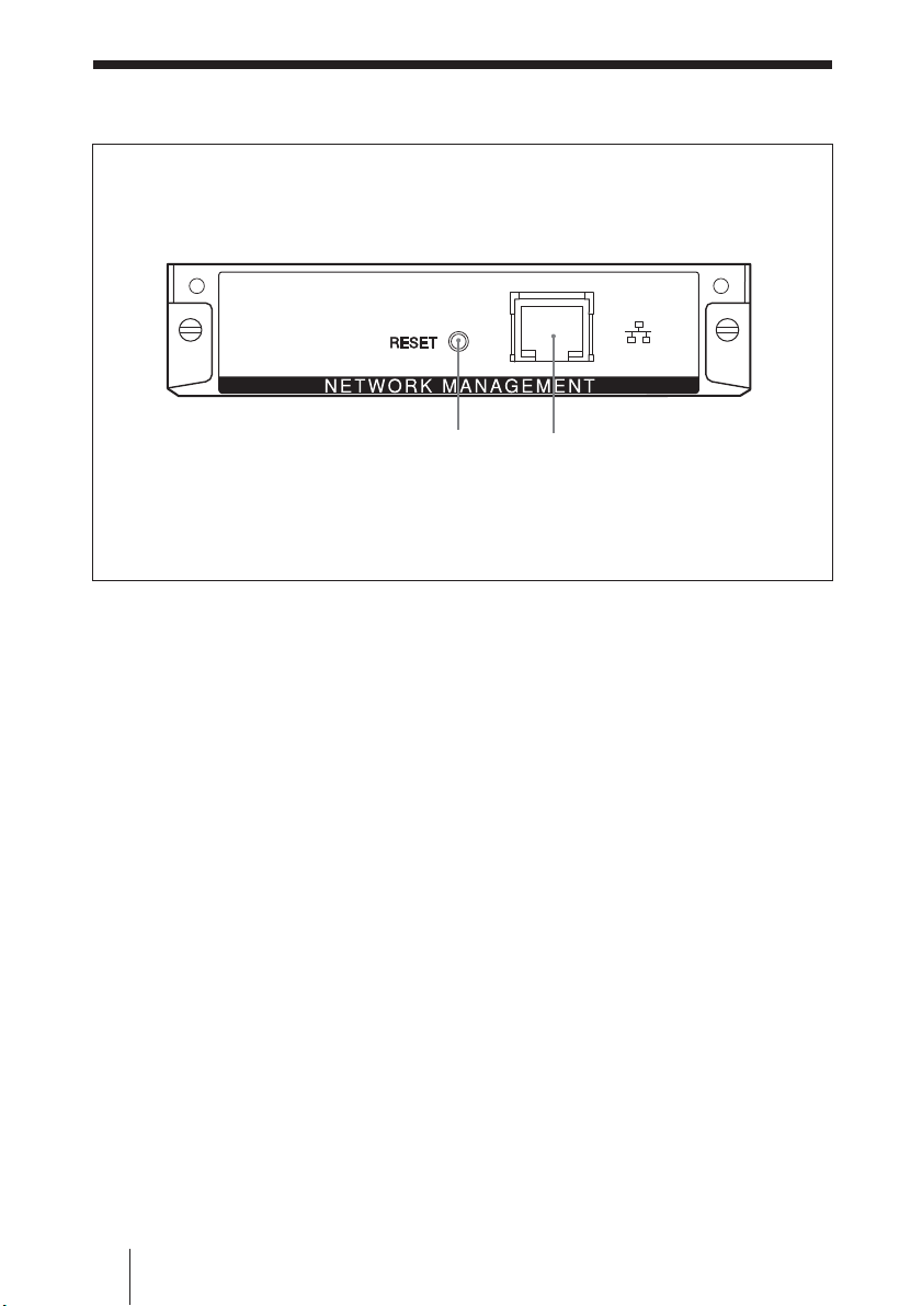
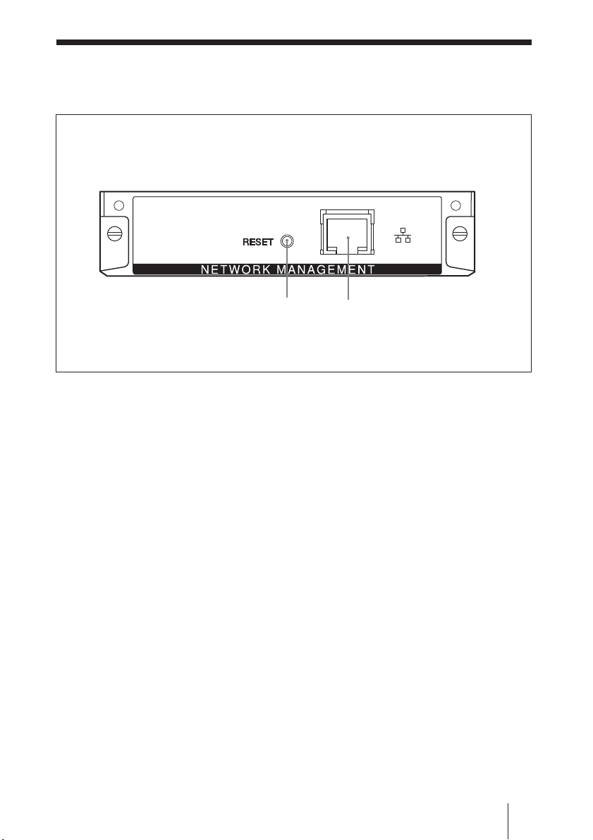
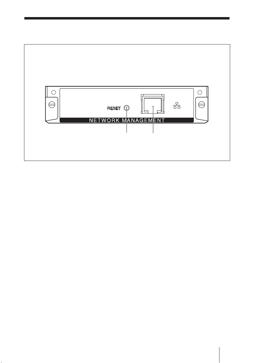
各部の名称と働き
RESET
ボタン
ネットワーク端子
RESET
3秒以上押したままにすると、各種設定値
を初期化します。
ネットワーク端子(
100BASE-TX
本機を10BASE-T/100BASE-TX の LAN
ケーブルでネットワークと接続します 。
JP
ボタン
各部の名称と働き
6
10BASE-T/
)
Page 7
ネットワーク機
能を使う準備を
する
本機は、10BASE-T/100BASE-TXの LAN
ケーブル でネットワークに 接続することがで
きます 。
ここで は 、ネットワークに接 続し て 本 機 の
ネットワーク機 能を使うために必要な準備に
ついて説明します。
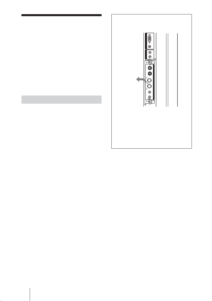
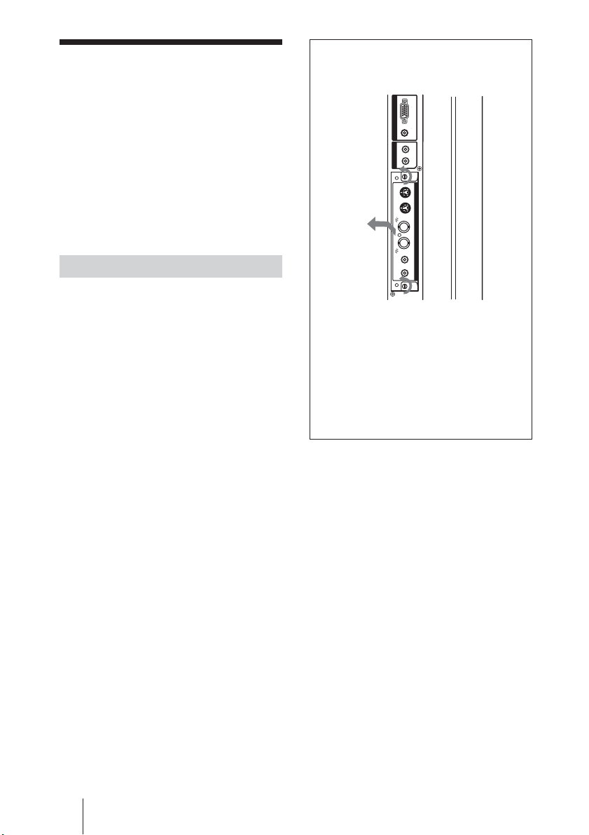
本機を取り付ける
オプションス
ロットがディ
スプレイの左
側面にある場
*
合
INPUT 2
OUT
AUDIO
RGB / COMPONENTAUDIO
L
R
1
INOUTINOUTRL
S VIDEO
2
VIDEO
VIDEO INPUT ADAPTOR
AUDIO IN
1
*オプションスロットの位置は機種により
異なります。オプションスロットが複数あ
る機種の場合は、本機を通信機能対応
(
ポート)のスロットへ取り付けてく
COM
ださい。
わせてご確認ください。
シリーズの取扱説明書もあ
FWD
取り付ける前に
• ディスプレイとディスプレイにつなが れて
いるすべての機器の電源を切ってくださ
い。特にディスプレイについては、ディス
プレイの 1スイッチを 押してスタンバイ状
態にし、電源コードをコンセントから 抜 い
た後取り付けを行ってください。
• 取り付け 作 業は 、ディスプレイ本体を 安 定
した状態に固定して行ってください。
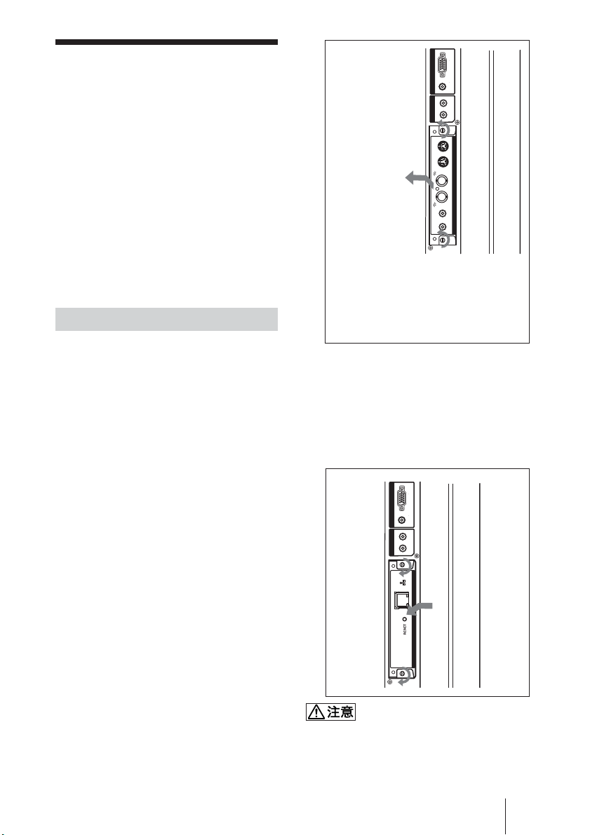
本機(BKM-FW32)を以下の手順に従っ
て、ディスプレイ本 体に 取り付 け てください。
すでに取り付けられているオプション
1
アダプターの上下にあるネジ(
2
本)
をマイナスドライバーを使って反時計
方向回りにゆるめ、オプションアダプ
ターをゆっくりとディスプレイ本体か
ら引き出す。
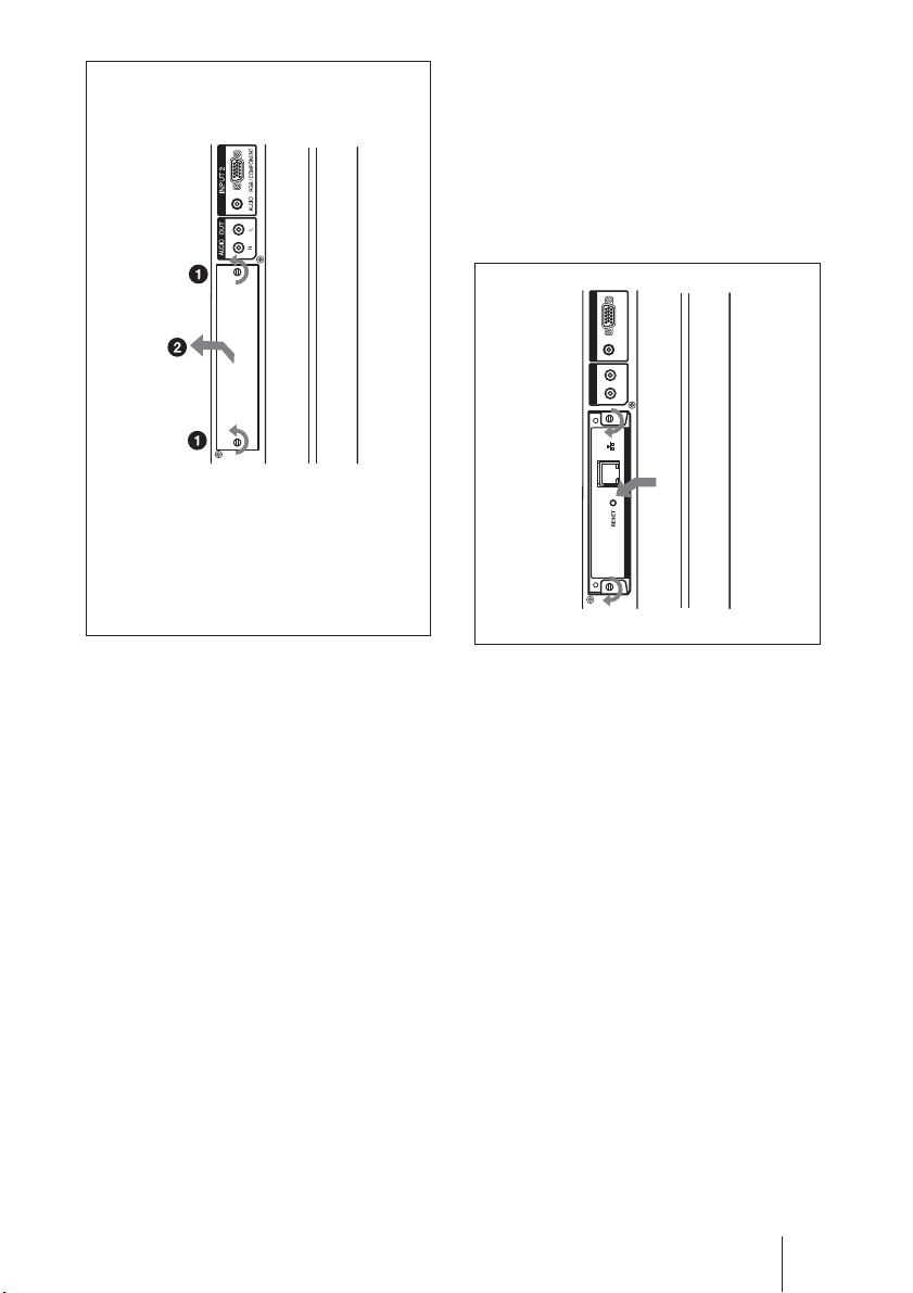
本機の上下を確かめて、ディスプレイ
2
本体に押し込む。
ディスプレイ内部 のコネクター部を確 実 に
接続してください。上下のネジ(2本)をマ
イナ スドライバー で 締 め て、必要な配線を
してください。
RGB / COMPONENTAUDIO
INPUT 2
L
OUT
R
AUDIO
2
1
NETWORK MANAGEMENT
2
コネクター部には手を触れない
ディスプレイ内部 のコネクター 部 には 手を 触
れないでください。けがをしたり故障の原因
となることが あります 。
ネットワーク機能を使う準備をする
JP
7
Page 8
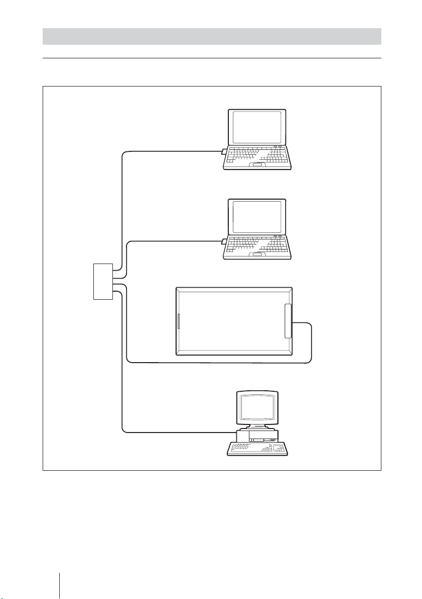
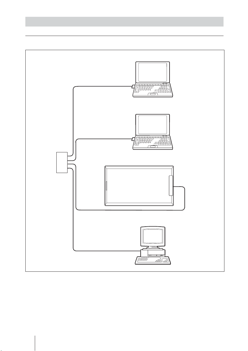
システム構成
ケーブルでネットワークに接続する
LAN
ケーブル
LAN
ケーブル
LAN
ハブ/
ルーターへ
LAN
ケーブル
コンピューター
コンピューター
ディスプレイ(本機)
ネット
ワーク
端子
ケーブル
LAN
LANに接続して使用するときは、IPアドレ
スの設定が必要です。IPアドレ ス の 自動取
得の環境(DHCP環境)下でご使用くださ
い。
JP
ネットワーク機能を使う準備をする
8
コンピューター
設定されたIPアドレス の 情 報 は 、ディスプレ
イの メ ニ ュー から、インフォメーションまたは
ステータスの ペ ージ で 確認することができま
す。
Page 9

ネットワーク環境 が変わったときは、IPアドレ
スを 再設定する必要があります。
• DHCP環境のとき
LANケーブルを抜き差しすることに より、
自動的にIPアドレ スが再設定されます。
• マニュアルで設定されたとき
環境にあわせて設定の変更を行ってくだ
さい。
ご注意
アドレスをマニュアルで設定するには
IP
IPアドレスを 自動で設定できない場合は、
以下の手順に従ってマニュアルで設定す
ることが で きます。
本機とコンピューターをクロスタイ
1
プの
ケーブルで直接接続する。
LAN
11(JP
6
の
る。
クロスタイプの
7
し、通常のストレートタイプの
ケーブルで接続させたいネットワー
ク( 固 定
ク)へ接続する。
ご注意
設定に不具合がある場合は、RESETボタン
を3秒以上押したままにして設定を初期化
してから、あら た め て 手 順1から設 定しなお
してください。
)ページの手順に従い、本機
アドレスをマニュアルで設定す
IP
ケーブルをはず
LAN
を使っているネットワー
IP
LAN
コンピューターを「
2
動的に取得する」に設定する。
本機を取り付けたディスプレイの電
3
源を入れる。
約30秒後、ディスプレイのメニュー
4
画面で本機の
る。
確認したIPアドレスをコンピュー
5
ターのブラウザーでアクセスする。
ご注意
アクセスできない場合には
• ブラウザーで Proxyを使わないように設
定してください 。
• コンピューターのIP が 169.254.xxx.xxx、
Subnet Maskが 255.255.0.0 でない場
合、手動でそれぞれを設定してください 。
IP Address
アドレスを確認す
IP
を自
ネットワーク機能を使う準備をする
JP
9
Page 10

コンピューター
Information
画面
で操作する
ディスプレイをコントロールする
コンピ ューター の 画面上でディスプレイの各
種設定ができます。
本機がディスプレイにしっかり装 着され て い
ること、本機、コンピューター、ルーターまた
はハブがネットワークケーブ ル で接続されて
いることを確認し、ディスプレイとコンピュー
ター、ルーターまたは ハブ の 電源を入れてく
ださい。
ディスプレイコントロール 画 面 は 、機 能 別に
「Information」画面、「Configuration」画
面、「Control」画面、「Setup」画面の4 画
面を表示 できます。
◆ボタンの働きについて詳しくは、ディスプレイ
本体、FWDシリーズの取扱説明書もあわせ
てご覧ください。
コンピューターのブラウザ(
1
Explorer 6.0
アドレスに「
2
(本機のIPアドレス)」と入力し、キー
ボードの
本機のIPアドレスは、ディスプレイの
「Information」メニュー で 確 認できます。
ユーザー名とパスワードが設定され ている
と、NetworkPassword(ネットワークパス
ワード)入力画面が表示されます。設定し
たユーザー名とパスワードを 入 力し て か
ら、次 の 手 順 に進んでください。
以上)を起動する。
http ://xxx.xxx.xxx.xxx
キーを押す。
Enter
Internet
ModelName(モデル名)やSerialNo.(シ
リア ル番号)等のディスプレイの情報や、
POWER(電源)やINPUT(入力信号)な
どのディスプレイの現 在 の 状態などを表示
します。
この画面は確認のみで、設定の変更はで
きませ ん 。
Configuration
(タイマー)
Timer
タイマーを 設 定しま す 。
設定後Applyをクリックします。
Screen Saver
スクリーンセーバーを設 定します。
設定後Applyをクリックします。
Picture and Picture(2
2画面の設定をします。
設定後Applyをクリックします。
ご注意
各機能については、ディス プレイ本体、
FWDシリーズの取扱説明書もあわせてご
覧ください。ディスプレイのモ デ ルによって
対応していない機能もあります。
画面
(スクリーンセーバー)
画面)
画面上部の機能タブをクリックして表
3
示したい画面を選ぶ。
JP
10
コンピューターで操作する
Page 11

Control
画面
Set up
画面
POWER
ディスプレイの 電源 の 入 / 切を切り換えま
す。
INPUT
入力信号を切り換えます。
PICTURE MODE
ピクチャーモードを 切り換 えます 。
ASPECT
画面の縦横比を切り換えます。
CLOSED CAPTION
プション)
英語字幕を画面に表示したいときに使用し
ます。
PICTUREMODEをUser1、User2、User3
に設定したとき、以下の調整ができます。
(FWDシリーズの取扱説明書もあわせてご
覧ください。)
Contrast
コントラストを調整します。
Brightness
画面の明るさを調整します。
Chroma
色の濃さを調整します。
Phase
色あいを調整します。
(電源)
(入力切換)
(ピクチャーモード)
(アスペクト)
(クローズドキャ
(コントラスト)+/− ボタン
(ブライトネス)+/− ボタン
(色の濃さ)+/− ボタン
(色あい)+/− ボタン
NetworkPassword(ネットワー ク パ ス ワ ー
ド)の入力画面が表示されます。お買い上
げ時は、次のように設定されています。
Name: root
Password: fw32ad
各画面で入力した情報、変更した設定など
は、各画面下方の「Apply」をクリックす ると
反映されます。
特殊文字は使用できません。
Owner Information
(所有者)
Owner
所有者の情報を入力します。
Display Location
ディスプレイのLocation(設置場所)を入力
します。
(メモ)
Memo
メモを 入 力し て おくことが で きま す 。
(ディスプレイ設置場所)
Time
(時刻)
Time
時刻と曜日を入力します。*
*曜日については、FWD-50PX1/50PX1Nには
対応していません。
Network
Internet Protocol (TCP/IP)
ネットプロトコル)
通常は、「ObtainanIPaddressautomatically
(DHCP)(IPアドレ スを 自動的に設定する)」
に設定します。「SpecifyanIPaddress(IPア
ドレスを 手動で設定する)」を選んだ場合は、
各数値を入力してください。
(インター
コンピューターで操作する
11
JP
Page 12

Password
管理者、ユーザーそれぞれに名前とパス
ワードを 設定できます。管理者の名前は
「root」に固定されています。
Mail Report
ディスプレイにエラーが発生した 場 合、すぐ
にメールで通知します(エラー通知)。
*FWD-50PX1/50PX1Nには対応していませ
ん。
Address
各テキストボックスに 送 信先のメールアドレ
スを 入 力しま す 。同 時 に4か所に送 信でき
ます。各アドレ スの 最大入力文字数は64文
字です。
Mail Account
Mail Address
割り当 てられたメールアドレ スを 入 力しま
す。
最大入力文字数は64 文字です。
Outgoing Mail Server (SMTP)
信メールサーバー):
メール サ ー バ ー の アドレスを 設 定します 。
最大入力文字数は64 文字です。
(パスワード)
(メールレポートの設定)
(送信先)
(メールアカウント)
(メールアドレ ス ):
(送
Requires the use of POP
Authentication before Send
e-mail (POP before SMTP)
(メール送信に
SMTPサーバーに接続する際にPOP 認
証を行う必要がある場合、チェックボック
スを チ ェックし てください。
Ingoing Mail Server (POP3)
認証が必要):
POP
(受信
メール サーバー):
「POPbeforeSMTP」でのPOP認証に使
用するPOP3サーバーのアドレ スを 入力し
ます。
*
Account Name
メール アカウントを入力します。
Password
メール パ スワードを 入 力します 。
Send Test Mail
指定したアドレスに メー ル が 送 信され るか
どうか 、テストメー ル を 送 信 す ること が で き
ます。チェックボックスをチェックし て
「Apply」をクリックす ると 送 信され ま す 。
ご注意
以下の項目が設定されていな い か、設定
が正しくない場合には、エラーメッセージ が
表示され、テストメールは送信できません。
• 送信先のアドレ ス
• メー ル ア カウントの メール アドレスと送 信
メール サーバー(SMTP)
Advanced
ネットワーク上 で 各種 アプリケーションを利 用
可能にする高度な設定を行います。ご利用
のアプリケーションの設定要求とあわせてご
確認ください。
RESET
Setup 画面で入力した設定値を初期化す
るには、細い棒状のものでRESETボタンを
3秒以上押したままにしてください。すべて
の入力情報が消去されます。
(高度な設定)
ボタンについて
(アカウント名 ):
(パスワード):
(テストメー ル送信):
JP
コンピューターで操作する
12
Page 13

トラブル時の対処
サービス窓口にご相談になる前に下記の項目をもう一 度 チ ェックしてみてください。それで
も具合の悪いときは、ソニーのサービス窓口にご相談ください 。
症状 原因/対処
ネットワ ー ク に 接 続 で き な い 。
・本機がディスプレイに正しく取り付けられ て いない。
t 本機を奥までしっかり差し 込 み 、固 定 ネジを締 め てください。
・ネットワ ーク 端 子 に ケ ー ブ ル が 正しく接続されていない。
t ケーブルを奥までしっかり差し 込 ん でください。
・ネットワ ーク の 設 定 が 正 しくない。
t コンピューター の Webブラウザから操作している場合、コン
ピューターのネットワーク設 定を 確 認してください 。
本機のRESETボタンを3秒以上押したままにして初期設定
状態に戻し、あらためて設定しなおしてください。
・ケーブルの種類が適切でない。
t ストレートケ ー ブ ル また は クロ スケーブ ルを ネットワーク環 境に
合わせてご使用ください。
トラブル時の対処
13
JP
Page 14

仕様
入/出力
Network 10BASE-T/100BASE-
TX(ネットワークの 使
用環境により、接続速
度に差が生じることが
あります 。)
その他
最大外形寸法 135× 30 × 90mm
(幅/高さ/奥行き)
質量 約120g
消費電力 約1.0W
動作温度 0〜35℃(本機を装着し
たディスプレイの環境)
保存温度 −10 〜+40℃
LED Link(緑)/
Act(オレンジ)
ケーブル長 100m以内(カテゴリー
5)
本機の仕様および外観は改良のため予告
なく変更 することがあります が 、ご 了承くだ
さい。
JP
仕様
14
Page 15

Page 16

WARNING
Owner’s Record
The model and serial numbers are located at
the rear. Record these numbers in the
spaces provided below.
Refer to these numbers whenever you call
upon your Sony dealer regarding this
product.
Model No.
Serial No.
To prevent fire or shock hazard,
do not expose the unit to rain or
moisture.
To avoid electrical shock, do not
open the cabinet. Refer servicing
to qualified personnel only.
For the Customers in the U.S.A.
If you have any questions about this
product, you may call; Sony Customer
Information Services Center
1-800-222-7669 or http://www.sony.com/
Declaration of Conformity
Trade Name: SONY
Model: BKM-FW32
Responsible Party: Sony Electronics
Inc.
Address: 16450 W. Bernardo
Dr, San Diego,
CA 92127 U.S.A.
Telephone Number: 858-942-2230
This equipment has been tested and found
to comply with the limits for a Class B digital
device, pursuant to Part 15 of the FCC
Rules. These limits are designed to provide
reasonable protection against harmful
interference in a residential installation. This
equipment generates, uses, and can radiate
radio frequency energy and, if not installed
and used in accordance with the
instructions, may cause harmful interference
to radio communications. However, there is
no guarantee that interference will not occur
in a particular installation. If this equipment
does cause harmful interference to radio or
television reception, which can be
determined by turning the equipment off and
on, the user is encouraged to try to correct
the interference by one or more of the
following measures:
• Reorient or relocate the receiving antenna.
• Increase the separation between the
equipment and receiver.
• Connect the equipment into an outlet on a
circuit different from that to which the
receiver is connected.
• Consult the dealer or an experienced radio/
TV technician for help.
You are cautioned that any changes or
modifications not expressly approved in this
manual could void your authority to operate
this equipment.
For customers in Canada
This Class B digital apparatus complies with
Canadian ICES-003.
This device complies with Part 15 of the
FCC Rules. Operation is subject to the
following two conditions: (1) This device may
not cause harmful interference, and (2) this
device must accept any interference
received, including interference that may
cause undesired operation.
GB
2
Page 17

Table of Contents
Precautions...................................... 4 (GB)
About This Manual .......................... 4 (GB)
Location and Function of Parts and
Controls ........................................ 5 (GB)
Preparations for Using the
Networking Function ................... 6 (GB)
Installing this device ........................... 6 (GB)
System Configuration ......................... 8 (GB)
Operations from a Computer ....... 10 (GB)
Controlling the Display from a Computer ...
Troubleshooting ............................ 13 (GB)
Specifications ................................ 14 (GB)
10 (GB)
GB
GB
3
Page 18

Precautions
About This Manual
• Please note that the software
specifications are subject to change
without notice.
• Some of the illustrations in this manual
may differ from the actual application
software.
• For your safety, connect to an Ethernet
network which does not exceed the
voltage limit of the Ethernet connector.
This manual explains networking
operations when this device is installed in
the FWD series Flat Panel Display.
Refer to the Operating Instructions for the
FWD series for operations other than
networking.
...........................................................................................................................................................................................................
• Microsoft and Windows are the registered trademarks of Microsoft Corporation in the
United States and/or other countries/regions.
• All other product and company names mentioned herein are trademarks or registered
trademarks of their respective owners.
GB
4 Precautions/About This Manual
Page 19
Location and Function of Parts and
Controls
Network connectorRESET button
RESET button
Press and hold the button for more than 3
seconds to clear the settings you made.
Network connector (10BASE-T/
100BASE-TX)
Connect this device to the network with the
LAN cable (10BASE-T/100BASE-TX).
Location and Function of Parts and Controls
GB
5
Page 20
Preparations for
Using the
Networking
Function
You can connect this device to the network
with a LAN cable (10BASE-T/100BASETX).
This section describes the tasks required for
using the networking function of this
device.
Installing this device
When the option slot is located on
the left side of a Display unit*
RGB / COMPONENTAUDIO
INPUT 2
L
OUT
R
AUDIO
1
INOUTINOUTRL
S VIDEO
2
VIDEO
VIDEO INPUT ADAPTOR
AUDIO IN
1
Before installation
• Before installation, make sure that the
power to all the equipment is off. To turn
the display completely off, press the 1
switch so that the display changes to
standby mode, then disconnect the power
cord from the wall outlet.
• When you install this device, make sure
that the flat panel display is locked and
stable.
Follow the steps below to install this device
to the FWD series Flat Panel Display.
1 Remove the installed option adaptor
or the panel cover. (Refer to either of
the following illustrations that applies
to your Display unit.)
* The location of the option slot differs
depending on the model of the Display
unit. If your Display unit has more than
one option slot, install the device in a
COM port, a slot used for the network.
Refer to the Operating Instructions for the
FWD series as well.
GB
Preparations for Using the Networking Function
6
Page 21
When the option slot is located on
the left side of a Display unit*
2 Check the direction (top/bottom) of
this device and insert it into the flat
panel display. Make sure that the
connector inside the Display is firmly
connected.
Using a slot screwdriver, tighten the
two screws of this device. Connect the
LAN cable, as needed.
RGB / COMPONENTAUDIO
INPUT 2
L
OUT
R
AUDIO
2
* The location of the option slot differs
depending on the model of the Display
unit. If your Display unit has more than
one option slot, install the device in a
COM port, a slot used for the network.
Refer to the Operating Instructions for the
FWD series as well.
1
NETWORK MANAGEMENT
2
Caution
Do not touch the connector inside the
Display. Doing so may result in injury to
yourself or cause this device to
malfunction.
Preparations for Using the Networking Function
GB
7
Page 22
System Configuration
Connecting to the network using LAN cables
LAN cable
LAN cable
to
Hub/router
Display (this device)
Computer
Computer
Network
connector
LAN
cable
LAN cable
When you use this device connected to a
LAN, you must set an IP address. Use this
device in a DHCP environment in which an
IP address is automatically obtained.
GB
Preparations for Using the Networking Function
8
Computer
You can confirm information such as the IP
address assigned to this device using the
Information page or the Unit Status page
selected from the menus of the Display
unit.
Page 23

If the network environment is changed, you
must set up a new IP address again.
• When using this device in a DHCP
envirnment;
Disconnect the LAN cable once, and then
connect it again. An IP address is
automatically obtained.
• When the IP address has been set
manually;
Modify the settings in accordance with the
new network environment.
NOTE
When you need to set an IP address
manually
When an IP address cannot be set
automatically, follow the steps below to set
an IP address manually.
1 Connect this device and the computer
directly using a crossover LAN cable.
2 Choose “Obtain an IP address
automatically” on the computer.
3 Turn on the power of the Display unit
in which this device is installed.
4 After about 30 seconds, confirm the
IP address assigned to this device
using the menu screen of the Display
unit.
6 Set the IP address manually on this
device following the steps given on
page 11 (GB).
7 Disconnect the crossover LAN cable,
then connect this device to a network
in which fixed IP addresses are used,
using a straight LAN cable.
NOTE
If you misconfigure the connection, press
and hold the RESET button for more than 3
seconds to clear the settings. Then repeat
the procedure from Step1.
5 Access the IP address confirmed in
Step 4 using your browser.
NOTE
When you cannot access the network
• Set the browser of the computer to access
the Internet without using a proxy server.
• If the IP address of the computer is not
169.254.xxx.xxx or the subnet mask is
not 255.255.0.0, change the settings to
those address values.
Preparations for Using the Networking Function
GB
9
Page 24

Operations from a
Computer
Controlling the Display from a
Computer
You can perform various adjustments and
settings of the Display on a computer’s
display. Check that this device is firmly
installed in the Display and that this device,
the personal computer, and the router or
hubs are connected via LAN cables. Then
turn on the Display, the computer, and the
router or hubs. Four control windows are
available; Information, Configuration,
Control, and Setup, each with distinct
functions.
For details on the functions of buttons, see the
Operating Instructions for the FWD series as
well.
Information window
This window displays information on the
Display unit, such as the Model name,
Serial No., and the current operating status
of the Display unit, including the presence
of power and an input signal.
This window only displays information.
You cannot change settings using this
window.
Configuration window
Timer
Sets the timer.
After setting the timer, click Apply.
Screen Saver
Sets the screen saver.
After setting the desired screen saver, click
Apply.
1 Start the computer’s browser (Internet
Explorer 6.0 or later).
2 Type “http://xxx.xxx.xxx.xxx (for the
IP address of this device)” and press
the ENTER key of the keyboard. You
can confirm the IP address assigned
to this device using the information
menu of the Display unit.
When a user name and password have
been set, the “Network Password”
screen appears. Enter the user name
and password that were set, and then
proceed to the next step.
3 Click the function tab to select the
window you want.
Picture and Picture
Sets the Picture and Picture mode.
After setting the desired mode, click Apply.
NOTE
Refer to the Operating Instructions for the
FWD series for details on each function as
well.
Depending on the Display model, some
functions are not available.
Control window
POWER (power switch)
Turns the power of the Display unit on or
off.
INPUT (input selector)
Switches the input signal.
PICTURE MODE (picture mode)
Switches the picture mode.
ASPECT (aspect)
Switches the width of the screen display.
GB
Operations from a Computer
10
Page 25

CLOSED CAPTION (closed caption)
Displays closed captions.
When PICTURE MODE is set to any of
User1, User2 and User3, you can adjust the
following items.
Refer to the Operating Instructions for the
FWD series as well.
Time
Time
Enter the current time and the day of the
week.*
* For the FWD-50PX1/50PX1N, enter the
current time only.
Contrast +/– buttons
Adjusts the picture contrast.
Brightness +/– buttons
Adjusts the picture brightness.
Chroma +/– buttons
Adjusts color intensity.
Phase +/– buttons
Adjusts color tones.
Setup window
“Network Password” screen appears.
The factory default settings are as fallows:
Name: root
Password: fw32ad
After you have made any changes or
entered information, click “Apply” at the
bottom of each screen to enable the
settings. Special characters cannot be used
in the text fields.
The settings entered or changed in each
window become valid after you click Apply
located near the bottom of the window.
You cannot enter special characters in this
window.
Owner Information
Owner
Enter information on the owner.
Display Location
Enter the location of the Display unit.
Memo
You can write comments or notes here.
Network
Internet Protocol (TCP/IP)
Under normal circumstances, set this item
to “Obtain an IP address automatically
(DHCP).” Enter the required value
(address) if you set it to “Specify an IP
address.”
Password
Names and Passwords can be set
individually for the Administrator and each
User. The Name for the Administrator is
permanently set to “root.”
Mail Report*
If an error occurs inside the Display unit,
the system immediately reports the error by
sending an e-mail (Error Report).
* Except for the FWD-50PX1/50PX1N.
Address (Destination)
Enter an e-mail address in each text box.
The error report can be sent to four
destinations at the same time. The
maximum number of characters of each email address is 64.
Mail Account
Mail Address:
Enter the e-mail address assigned to this
device.
The maximum number of characters of the
address is 64.
Outgoing Mail Server (SMTP) (SMTP
server):
Enter the address of the SMTP server.
The maximum number of characters of the
address is 64.
Operations from a Computer
11
GB
Page 26

Requires the use of POP
Authentication before Send e-mail
(POP before SMTP):
Check the “POP before SMTP” check box
when POP authentication is needed before
connecting to the SMTP server.
Ingoing Mail Server (POP3):
Enter the address of the POP3 server to be
used for POP Authentication (POP before
SMTP).
Account Name:
Enter the name of the e-mail account.
Password:
Enter the password for the e-mail account.
Send Test Mail:
A test e-mail message can be sent to
specified destinations. Check this check
box and click Apply to send a test e-mail.
NOTE
If the following items are not set or the
settings are incorrect, an error message
appears and the test e-mail message cannot
be sent.
• Destination addresses
• The Mail Address of the Mail Account
and the address of the SMTP server
Advanced (Advanced settings)
Sets the advanced settings required to use
various application software on the
network. Refer to the setting requirements
of the application software you want to use
as well.
RESET button
Press and hold this button using a thin stick
for more than 3 seconds to clear all the
settings you made in the Setup window.
GB
Operations from a Computer
12
Page 27

Troubleshooting
If the Display appears to be operating erratically, try to diagnose and correct the problem,
refering to the following guide. If the problem still persists, consult with qualified Sony
personnel.
Symptom
A connection to the network is not
established.
Causes and remedies
• This device is not properly installed.
t Push this device into the slot until it is
firmly seated and tighten the two screws.
• The cable is not properly connected to the
Network connector.
t Insert the plug of the cable to the connector
firmly.
• The network environment is not properly set
up.
t When you use the computer’s web browser,
check the network settings on the computer.
Press and hold the RESET button for more
than 3 seconds to clear the settings, and
then configure the network environment
again.
• The cable used to connect this device to the
network is not correct.
t Use a straight cable or a crossover cable
that is appropriate to your network
environment.
Troubleshooting
13
GB
Page 28

Specifications
Input/Output
Network 10BASE-T/100BASE-
General
Dimensions 135 × 30 × 90 mm
Mass Approx. 120 g (4 oz)
Power consumption
Operating temperature
Storage temperature
LED Link (Green) /
Cable length limit
TX (Network
connection speed may
vary depending on the
network
environment.)
3
/8 × 1 3/16 × 3 5/8
(5
inches) (w/h/d)
Approx. 1.0 W
0°C to 35°C
(32°F to 95°F) (The
ambient temperature
at which you use the
display unit with this
device installed)
–10°C to +40°C
(14°F to 104°F)
Act (Orange)
Within 100 m (Category
5)
Design and specifications are subject to
change without notice.
GB
14
Specifications
Page 29

Page 30

AVERTISSEMENT
Afin d’éviter tout risque
d’incendie ou d’électrocution,
n’exposez pas cet appareil à la
pluie ou à l’humidité.
Afin d’éviter tout risque
d’électrocution, n’ouvrez pas le
châssis. Confiez l’entretien
uniquement à un personnel
qualifié.
Pour les utilisateurs au Canada
Cet appareil unmérique de la classe B est
conforme à la norme NMB-003 du Canada.
FR
2
Page 31

Table des matières
Précautions....................................... 4 (FR)
A propos de ce manuel.................... 4 (FR)
Emplacement et fonctionnement des
pièces et des commandes ........... 5 (FR)
Préparation à l’utilisation de la fonction
de gestion de réseaux .................. 6 (FR)
Installation de l’appareil ..................... 6 (FR)
Configuration système ........................ 8 (FR)
Opérations à partir d’un ordinateur ....
Contrôle de l’écran à partir
d’un ordinateur ...................... 10 (FR)
Guide de dépannage ...................... 13 (FR)
Spécifications ................................. 14 (FR)
10 (FR)
FR
FR
3
Page 32

Précautions
A propos de ce
• Notez que les spécifications du logiciel
sont sujettes à modifications sans préavis.
• Certaines illustrations du présent manuel
peuvent être légèrement différentes de ce
qui apparaît réellement dans le logiciel.
• Pour votre sécurité, raccordez-vous à un
réseau Ethernet dont la tension est
inférieure à la tension limite du
connecteur Ethernet.
manuel
Ce manuel explique les opérations de
gestion de réseaux lorsque l’appareil est
raccordé à un moniteur à écran plat de la
série FWD.
Reportez-vous au mode d’emploi de la série
FWD pour les opérations autres que la
gestion de réseaux.
...........................................................................................................................................................................................................
• Microsoft et Windows sont des marques déposées de Microsoft Corporation aux Etats-Unis
et/ou dans d’autres pays/régions.
• Tous les autres noms de produits et de sociétés mentionnés dans le présent manuel sont des
marques commerciales ou des marques déposées de leurs propriétaires respectifs.
FR
4 Précautions/A propos de ce manuel
Page 33
Emplacement et fonctionnement des pièces
et des commandes
Connecteur réseauTouche RESET
Touche RESET
Appuyez sur la touche et maintenez-la
enfoncée pendant plus de 3 secondes pour
effacer les réglages effectués.
Connecteur réseau (10BASE-T/
100BASE-TX)
Raccordez cet appareil au réseau à l’aide du
câble LAN (10BASE-T/100BASE-TX).
Emplacement et fonctionnement des pièces et des commandes
FR
5
Page 34

Préparation à
l’utilisation de la
Lorsque l’emplacement optionnel est situé
sur le côté droit d’un moniteur*
fonction de gestion
de réseaux
Vous pouvez raccorder cet appareil au
réseau à l’aide du câble LAN (10BASE-T/
100BASE-TX).
Cette section décrit les tâches requises pour
utiliser la fonction de gestion de réseaux de
cet appareil.
Installation de l’appareil
Avant l’installation
• Avant de procéder à l’installation,
assurez-vous que tous les appareils sont
hors tension. Pour mettre le moniteur
complètement hors tension, appuyez sur
le commutateur 1 de façon que le
moniteur passe en mode de veille, puis
débranchez le cordon d’alimentation de la
prise murale.
• Lorsque vous installez cet appareil,
veillez bien à ce que le moniteur à écran
plat soit verrouillé et stable.
Suivez les étapes ci-dessous pour installer
cet appareil sur le moniteur à écran plat de
la série FWD.
RGB / COMPONENTAUDIO
INPUT 2
L
OUT
R
AUDIO
1
INOUTINOUTRL
S VIDEO
2
VIDEO
VIDEO INPUT ADAPTOR
AUDIO IN
1
* La place de l’emplacement optionnel varie
selon le modèle du moniteur. Si votre
moniteur possède plusieurs
emplacements optionnels, installez le
périphérique sur un port COM réservé aux
communications en réseau.
Reportez-vous également au mode
d’emploi de la série FWD.
1 Retirez l’adaptateur en option déjà
installé ou le couvercle du panneau.
(Reportez-vous aux deux illustrations
suivantes concernant votre moniteur.)
FR
Préparation à l’utilisation de la fonction de gestion de réseaux
6
Page 35

Lorsque l’emplacement optionnel est situé
sur le côté droit d’un moniteur*
2 Vérifiez le sens (haut/bas) de cet
appareil et insérez-le dans le
moniteur à écran plat. Assurez-vous
que le connecteur est correctement
branché à l’intérieur du moniteur.
A l’aide d’un tournevis plat, serrez les
deux vis de cet appareil. Raccordez le
câble LAN, si nécessaire.
RGB / COMPONENTAUDIO
INPUT 2
L
OUT
R
AUDIO
2
* La place de l’emplacement optionnel
varie selon le modèle du moniteur. Si
votre moniteur possède plusieurs
emplacements optionnels, installez le
périphérique sur un port COM réservé
aux communications en réseau.
Reportez-vous également au mode
d’emploi de la série FWD.
1
NETWORK MANAGEMENT
2
Attention
Ne touchez pas les connecteurs situés à
l’intérieur du moniteur.
Vous risqueriez de vous blesser ou
d’endommager l’appareil.
Préparation à l’utilisation de la fonction de gestion de réseaux
FR
7
Page 36

Configuration système
Connexion au réseau à l’aide des câbles LAN
Câble LAN
Câble LAN
vers le hub/
routeur
Moniteur (cet appareil)
Câble
LAN
Ordinateur
Ordinateur
Connecteur
réseau
Câble LAN
Lorsque vous utilisez cet appareil alors
qu’il est raccordé à un réseau local, vous
devez définir une adresse IP. Utilisez cet
appareil dans un environnement DHCP
dans lequel vous obtenez immédiatement
une adresse IP.
FR
Préparation à l’utilisation de la fonction de gestion de réseaux
8
Vous pouvez vérifier les informations telles
que l’adresse IP définie pour cet appareil à
la page « Information » (Informations) ou à
la page « Unit Status » (Statut de l’appareil)
à laquelle vous accédez à l’aide du menu du
moniteur.
Ordinateur
Page 37

Si l’environnement réseau est modifié, vous
devez configurer une nouvelle adresse IP.
• Lorsque vous utilisez cet appareil dans un
environment DHCP : débranchez une fois
le câble LAN, puis rebranchez-le. Une
adresse IP est automatiquement générée.
• Une fois l’adresse IP définie
manuellement : modifiez la configuration
en fonction du nouvel environment
réseau.
REMARQUE
Si vous devez configurer une adresse IP
manuellement
Lorsqu’il est impossible de configurer une
adresse IP automatiquement, suivez les
étapes ci-dessous pour la définir
manuellement.
1 Raccordez directement cet appareil à
l’ordinateur en utilisant un câble
LAN croisé.
2 Choisissez « Obtain an IP address
automatically » (Obtenir une adresse
IP automatiquement) sur l’ordinateur.
3 Mettez le moniteur sur lequel cet
appareil est installé sous tension.
6 Réglez l’adresse IP manuellement sur
cet appareil en suivant les étapes
mentionnées à la page 11 (FR).
7 Débranchez le câble LAN croisé, puis
raccordez cet appareil à un réseau
dans lequel des adresses IP fixes sont
utilisées, à l’aide d’un câble LAN
droit.
REMARQUE
Si vous avez mal configuré la connexion,
appuyez sur la touche RESET et
maintenez-la enfoncée pendant plus de 3
secondes pour effacer les réglages.
Recommencez ensuite la procédure à partir
de l’étape 1.
4 Après environ 30 secondes, vérifiez
l’adresse IP attribuée à cet appareil à
l’aide de l’écran de menu du
moniteur.
5 Accédez à l’adresse IP validée à
l’étape 4 à l’aide de votre navigateur.
REMARQUE
Si vous ne parvenez pas à accéder au réseau
• Configurez le navigateur de l’ordinateur
de façon à pouvoir accéder à Internet sans
utiliser de serveur proxy.
• Si l’adresse IP de l’ordinateur est
différente de 169.254.xxx.xxx ou si le
masque de sous-réseau est différent de
255.255.0.0, modifiez les réglages afin
qu’ils correspondent à ces valeurs.
Préparation à l’utilisation de la fonction de gestion de réseaux
FR
9
Page 38

Opérations à partir
d’un ordinateur
Contrôle de l’écran à partir
d’un ordinateur
Vous pouvez exécuter divers réglages et
paramétrages de l’écran sur un écran
d’ordinateur. Vérifiez que cet appareil est
correctement installé dans le moniteur et
que cet appareil, le PC et le routeur ou les
hubs (concentrateurs) sont raccordés par
des câbles LAN. Mettez ensuite le
moniteur, l’ordinateur et le routeur ou les
hubs sous tension. Quatre fenêtres de
commandes sont disponibles : Information,
Configuration, Control et Setup, présentant
chacune des fonctions différentes.
Pour plus de détails concernant le
fonctionnement des boutons, reportez-vous
également au mode d’emploi de la série FWD.
1 Lancez le navigateur de l’ordinateur
(Internet Explorer 6.0 ou une version
ultérieure).
2 Tapez « http://xxx.xxx.xxx.xxx (pour
l’adresse IP de cet appareil) », puis
appuyez sur la touche ENTER du
clavier. Vous pouvez vérifier
l’adresse IP de cet appareil dans le
menu d’information du moniteur.
Lorsqu’un nom d’utilisateur et un
mot de passe ont été définis, l’écran
« Network Password » (Mot de passe
réseau) s’affiche. Saisissez le nom
d’utilisateur et le mot de passe
définis, puis passez à l’étape suivante.
3 Cliquez sur l’onglet correspondant
pour sélectionner la fenêtre souhaitée.
Fenêtre Information (Informations)
Cette fenêtre affiche les informations
relatives au moniteur telles que le nom du
modèle, le numéro de série et l’état de
fonctionnement actuel du moniteur, y
compris la présence de tension et d’un
signal d’entrée.
Cette fenêtre ne fait qu’afficher les
informations.
Vous ne pouvez pas en modifier les
réglages.
Fenêtre Configuration
(Configuration)
Timer (Minuterie)
Active la minuterie.
Une fois la minuterie réglée, cliquez sur
Apply (Appliquer).
Screen Saver (Ecran de veille)
Active l’économiseur d’écran.
Une fois l’économiseur d’écran réglé,
cliquez sur Apply.
Picture and Picture (Image et image)
Active le mode Picture and Picture.
Une fois le mode de votre choix réglé,
cliquez sur Apply.
REMARQUE
Reportez-vous au mode d’emploi de la
série FWD pour obtenir plus de détails sur
chacune des fonctions.
Selon le modèle du moniteur, certaines
fonctions peuvent ne pas être prises en
charge.
Fenêtre Control (Commande)
POWER (Interrupteur)
Met le moniteur sous ou hors tension.
FR
Opérations à partir d’un ordinateur
10
INPUT (Sélecteur d’entrée)
Commute le signal d’entrée.
PICTURE MODE (Mode d’image)
Commute le mode d’image.
Page 39

ASPECT (Format)
Commute la largeur d’affichage de l’écran.
CLOSED CAPTION (Sous-titres)
Affiche les sous-titres.
Si PICTURE MODE est réglé sur User1,
User2 ou User3, vous pouvez ajuster les
éléments suivants.
Reportez-vous également au mode
d’emploi de la série FWD.
Display Location (Emplacement du
moniteur)
Permet de saisir l’emplacement du
moniteur.
Memo (Mémo)
Permet d’écrire des commentaires ou des
notes.
Time (Heure)
Boutons Contrast (Contraste) +/–
Règlent le contraste de l’image.
Boutons Brightness (Luminosité) +/–
Règlent la luminosité de l’image.
Boutons Chroma (Chroma) +/–
Règlent l’intensité des couleurs.
Boutons Phase (Phase) +/–
Règlent les tons des couleurs.
Fenêtre Setup (Installation)
L’écran « Network Password » (Mot de
passe réseau) apparaît.
Les paramètres réglés par défaut sont
comme suit :
Name (Nom) : root
Password (Mot de passe) : fw32ad
Une fois que vous avez effectué des
modifications ou saisi des informations,
cliquez sur « Apply » (Appliquer) en bas de
chaque fenêtre pour activer les réglages.
Il est impossible d’utiliser des caractères
spéciaux dans les zones de texte.
Les réglages définis ou modifiés dans
chaque fenêtre sont pris en compte une fois
que vous avez cliqué sur Apply en bas de la
fenêtre.
Vous ne pouvez pas saisir de caractères
spéciaux dans cette fenêtre.
Owner Information (Informations
concernant le propriétaire)
Time (Heure)
Spécifiez l’heure actuelle et le jour de la
semaine.*
* Pour le FWD-50PX1/50PX1N, spécifiez
l’heure actelle seulement.
Network (Réseau)
Internet Protocol (Protocole Internet)
(TCP/IP)
Dans des circonstances normales, réglez cet
élément sur « Obtain an IP address
automatically (DHCP) ». Saisissez la valeur
requise (adresse) si vous le réglez sur
« Specify an IP address ».
Password (Mot de passe)
Les noms et mots de passe peuvent être
définis individuellement pour
l’administrateur et pour chaque utilisateur.
Le nom de l’administrateur est toujours
« root ».
Mail Report (Rapport d’erreur)*
Si une erreur se produit au niveau du
moniteur, le système le signale
immédiatement en envoyant un e-mail
(Rapport d’erreur).
* Sauf pour le modèle FWD-50PX1/50PX1N.
Address (Destination)
Saisissez une adresse e-mail dans chaque
zone de texte. Le rapport d’erreur peut être
envoyé simultanément vers quatre
destinations. Chaque adresse e-mail peut
contenir au maximum 64 caractères.
Owner (Propriétaire)
Permet de saisir les informations relatives
au propriétaire.
Opérations à partir d’un ordinateur
11
FR
Page 40

Mail Account (Compte de messagerie)
Mail Address (Adresse de messagerie):
Saisissez l’adresse e-mail attribuée à cet
appareil.
L’adresse peut contenir au maximum
64 caractères.
Outgoing Mail Server (SMTP) (Serveur
de messagerie pour courrier sortant)
(SMTP server) (Serveur SMTP):
Saisissez l’adresse du serveur SMTP.
L’adresse peut contenir au maximum
64 caractères.
Requires the use of POP
Authentication before Send e-mail
(POP before SMTP) (Requiert une
authentification POP avant l’envoi de
courrier (POP avant SMTP)) :
Cochez la case à cocher « POP before
SMTP » si une authentification POP est
nécessaire avant le raccordement au serveur
SMTP.
Ingoing Mail Server (Serveur de
messagerie pour courrier entrant)
(POP3) :
Saisissez l’adresse du serveur POP3 à
utiliser pour l’authentification POP (POP
before SMTP).
Account Name (Nom du compte):
Saisissez le nom du compte e-mail.
Password (Mot de passe):
Saisissez le mot de passe du compte e-mail.
Send Test Mail (Envoyer courrier test):
Un e-mail test peut être envoyé aux
destinations spécifiées. Cochez cette case à
cocher et cliquez sur Apply afin d’envoyer
un e-mail test.
Advanced (Réglages avancés)
Permet de définir les réglages avancés
requis pour utiliser divers logiciels
d’application sur le réseau. Reportez-vous
également aux exigences de réglage du
logiciel d’application que vous souhaitez
utiliser.
Touche RESET (Reinitialiser)
Appuyez sur cette touche et maintenez-la
enfoncée à l’aide d’une fine tige pendant
plus de 3 secondes pour effacer les réglages
effectués dans la fenêtre Setup.
REMARQUE
Si les éléments suivants ne sont pas définis
ou si les réglages sont incorrects, un
message d’erreur apparaît et il se peut que
l’e-mail test ne soit pas envoyé :
• les adresses de destination ;
• Mail Address dans Mail Account et
l’adresse du serveur SMTP.
FR
Opérations à partir d’un ordinateur
12
Page 41

Guide de dépannage
Si l’ordinateur ne fonctionne pas correctement, essayez d’en déterminer la cause et de
remédier au problème, à l’aide du guide suivant. Si le problème persiste, consultez le
personnel qualifié Sony.
Symptôme
La connexion au réseau n’est pas
établie.
Causes et solutions
• Cet appareil n’est pas correctement installé.
t Insérez cet appareil dans l’emplacement
prévu à cet effet jusqu’à ce qu’il soit
correctement installé et serrez les deux vis.
• Le câble n’est pas correctement raccordé au
connecteur réseau.
t Insérez fermement la fiche du câble dans le
connecteur.
• L’environnement réseau n’est pas configuré
correctement.
t Si vous utilisez le navigateur Web de
l’ordinateur, vérifiez les réglages réseau de
ce dernier.
Appuyez sur la touche RESET et
maintenez-la enfoncée pendant plus de 3
secondes pour effacer les réglages, puis
reconfigurez l’environnement réseau.
• Le câble utilisé pour raccorder cet appareil au
réseau ne convient pas.
t Utilisez un câble droit ou un câble croisé
adapté à votre environnement réseau.
Guide de dépannage
13
FR
Page 42

Spécifications
Entrée/Sortie
Réseau 10BASE-T/
100BASE-TX (La
vitesse de connexion
du réseau peut varier
selon l’environnement
réseau.)
Généralités
Dimensions 135 × 30 × 90 mm
Poids Environ 120 g (4 onces)
Consommation Environ 1,0 W
Température de fonctionnement
Température de stockage
Voyant à DEL Link (vert) / Act
Limite de la longueur du câble
3
/8 × 1 3/16 × 3 5/8
(5
pouces) (l/h/p)
0°C à 35°C
(32°F à 95°F)
(Température
ambiante à laquelle
vous utilisez le
moniteur sur lequel
cet appareil est
installé)
–10°C à +40°C
(14°F à 104°F)
(orange)
100 m maximum
(catégorie 5)
La conception et les spécifications sont
sujettes à modifications sans préavis.
FR
Spécifications
14
Page 43

Page 44

ACHTUNG
Um Feuergefahr und die Gefahr
eines elektrischen Schlags zu
vermeiden, setzen Sie das Gerät
weder Regen noch sonstiger
Feuchtigkeit aus.
Um einen elektrischen Schlag zu
vermeiden, öffnen Sie das
Gehäuse nicht. Überlassen Sie
Wartungsarbeiten stets nur
qualifiziertem Fachpersonal.
DE
2
Page 45

Inhalt
Sicherheitsmaßnahmen................... 4 (DE)
Zu dieser Bedienungsanleitung...... 4 (DE)
Lage und Funktion der Teile und
Bedienelemente ............................ 5 (DE)
Vorbereitungen zum Arbeiten mit der
Netzwerkfunktion ..........................6 (DE)
Installieren des Geräts ......................... 6 (DE)
Systemkonfiguration ........................... 8 (DE)
Betrieb von einem Computer aus ....10 (DE)
Steuern des Bildschirms von einem
Computer aus ......................... 10 (DE)
Störungsbehebung ........................13 (DE)
Technische Daten .......................... 14 (DE)
DE
DE
3
Page 46

Sicherheitsmaßnahmen
Zu dieser
• Beachten Sie bitte, dass die
Softwarespezifikationen
unangekündigten Änderungen
unterliegen.
• Einige der Abbildungen in dieser
Anleitung können sich von der
tatsächlichen Anwendungssoftware
unterscheiden.
• Schließen Sie dieses Gerät aus
Sicherheitsgründen an ein EthernetNetzwerk an, das den
Spannungshöchstwert des EthernetAnschlusses nicht überschreitet.
Bedienungsanleitung
In dieser Anleitung werden die
Netzwerkfunktionen erläutert, die zur
Verfügung stehen, wenn dieses Gerät in
einem Flachbildschirm der Serie FWD
installiert ist.
Andere Funktionen als die
Netzwerkfunktionen sind in der
Bedienungsanleitung zu den einzelnen
Modellen der Serie FWD erläutert.
...........................................................................................................................................................................................................
• Microsoft und Windows sind eingetragene Warenzeichen der Microsoft Corporation in den
USA und/oder anderen Ländern/Regionen.
• Alle anderen in diesem Handbuch erwähnten Produkt- oder Firmennamen sind
Warenzeichen oder eingetragene Warenzeichen der jeweiligen Eigentümer.
DE
4 Sicherheitsmaßnahmen/Zu dieser Bedienungsanleitung
Page 47

Lage und Funktion der Teile und
Bedienelemente
Taste RESET
Taste RESET
Wenn Sie die Taste länger als 3 Sekunden
gedrückt halten, werden die von Ihnen
vorgenommenen Einstellungen gelöscht.
Netzwerkanschluss (10BASE-T/
100BASE-TX)
Schließen Sie dieses Gerät über ein LANKabel (10BASE-T/100BASE-TX) an das
Netzwerk an.
Netzwerkanschluss
Lage und Funktion der Teile und Bedienelemente
DE
5
Page 48
Vorbereitungen zum
Arbeiten mit der
Wenn sich der Erweiterungssteckplatz an
der linken Seite des Bildschirms befindet*
Netzwerkfunktion
Sie können dieses Gerät über ein LANKabel (10BASE-T/100BASE-TX) an das
Netzwerk anschließen.
In diesem Abschnitt werden die Schritte
erläutert, die zum Arbeiten mit der
Netzwerkfunktion dieses Geräts
erforderlich sind.
Installieren des Geräts
Vorbereitungen für die Installation
• Überprüfen Sie vor dem Installieren, ob
alle Geräte ausgeschaltet sind. Um den
Bildschirm vollständig auszuschalten,
drücken Sie den Schalter 1, so dass der
Bildschirm in den Bereitschaftsmodus
wechselt, und ziehen Sie dann den
Netzstecker aus der Netzsteckdose.
• Vergewissern Sie sich beim Installieren
dieses Geräts, dass der Flachbildschirm
sicher und stabil steht.
Gehen Sie wie unten erläutert vor, um
dieses Gerät im Flachbildschirm der Serie
FWD zu installieren.
RGB / COMPONENTAUDIO
INPUT 2
L
OUT
R
AUDIO
1
INOUTINOUTRL
S VIDEO
2
VIDEO
VIDEO INPUT ADAPTOR
AUDIO IN
1
* Die Lage des Erweiterungssteckplatzes
hängt vom Bildschirmmodell ab. Wenn Ihr
Bildschirm über mehrere
Erweiterungssteckplätze verfügt,
installieren Sie das Gerät in einem COMAnschluss (Steckplatz für
Netzwerkfunktionen). Schlagen Sie bitte
auch in der Bedienungsanleitung zum
jeweiligen Modell der Serie FWD nach.
1 Entfernen Sie den bereits installierten
Zusatzadapter bzw. die
Anschlussfeldabdeckung. (Sehen Sie
dazu in derjenigen der folgenden
zwei Abbildungen nach, die Ihrem
Bildschirm entspricht.)
DE
Vorbereitungen zum Arbeiten mit der Netzwerkfunktion
6
Page 49

Wenn sich der Erweiterungssteckplatz an
der linken Seite des Bildschirms befindet*
* Die Lage des Erweiterungssteckplatzes
hängt vom Bildschirmmodell ab. Wenn Ihr
Bildschirm über mehrere
Erweiterungssteckplätze verfügt,
installieren Sie das Gerät in einem COMAnschluss (Steckplatz für
Netzwerkfunktionen). Schlagen Sie bitte
auch in der Bedienungsanleitung zum
jeweiligen Modell der Serie FWD nach.
2 Achten Sie darauf, welches die Ober-
und welches die Unterseite dieses
Geräts ist, und setzen Sie es dann
richtig herum in den Flachbildschirm
ein. Achten Sie darauf, dass der
Anschluss im Bildschirm fest
eingesteckt ist.
Ziehen Sie mit einem
Schlitzschraubenzieher die beiden
Schrauben dieses Geräts an. Schließen
Sie gegebenenfalls das LAN-Kabel an.
RGB / COMPONENTAUDIO
INPUT 2
L
OUT
R
AUDIO
2
1
NETWORK MANAGEMENT
2
Vorsicht
Berühren Sie nicht die Anschlüsse im
Bildschirm.
Andernfalls besteht Verletzungsgefahr und
es kann zu Fehlfunktionen an diesem Gerät
kommen.
Vorbereitungen zum Arbeiten mit der Netzwerkfunktion
DE
7
Page 50

Systemkonfiguration
Anschließen an ein Netzwerk über LAN-Kabel
LAN-Kabel
LAN-Kabel
an Hub/Router
Bildschirm (dieses Gerät)
Computer
Computer
Netzwerkanschluss
LANKabel
LAN-Kabel
Wenn Sie dieses Gerät an ein LAN
anschließen, müssen Sie eine IP-Adresse
einstellen. Verwenden Sie dieses Gerät in
einer DHCP-Umgebung, in der die IPAdresse automatisch zugewiesen wird.
DE
Vorbereitungen zum Arbeiten mit der Netzwerkfunktion
8
Computer
Informationen wie die für dieses Gerät
eingestellte IP-Adresse werden auf der
Seite „Informationen“ oder der Seite
„Gerätestatus“ angezeigt, die Sie über das
Menü des Bildschirms aufrufen können.
Page 51

Wenn sich die Netzwerkumgebung ändert,
müssen Sie die IP-Adresse erneut
einstellen.
• Wenn Sie dieses Gerät in einer DHCPUmgebung einsetzen
Lösen Sie das LAN-Kabel kurz und
scließen Sie es dann wieder an. Eine IPAdresse wird automatisch zugewiesen.
• Wenn die IP-Adresse manuell eingestellt
wurde
Ändern Sie die Einstellungen in
Übereinstimmung mit der neuen
Netzwerkumgebung.
HINWEIS
Wenn Sie die IP-Adresse manuell
einstellen müssen
Wenn die IP-Adresse nicht automatisch
eingestellt werden kann, stellen Sie sie wie
im Folgenden erläutert manuell ein.
1 Verbinden Sie dieses Gerät über ein
gekreuztes LAN-Kabel direkt mit
dem Computer.
2 Wählen Sie am Computer „IP-
Adresse automatisch beziehen“.
3 Schalten Sie den Bildschirm, in dem
dieses Gerät installiert ist, ein.
6 Stellen Sie die IP-Adresse für dieses
Gerät wie in den Schritten auf Seite
11 (DE) erläutert manuell ein.
7 Trennen Sie das gekreuzte LAN-
Kabel vom Gerät und schließen Sie
dieses Gerät über ein ungekreuztes
LAN-Kabel an ein Netzwerk an, in
dem feste IP-Adressen verwendet
werden.
HINWEIS
Wenn Sie die Verbindung falsch
konfigurieren, halten Sie die Taste RESET
länger als 3 Sekunden gedrückt, um die
Einstellungen zu löschen. Gehen Sie dann
nochmals wie ab Schritt 1 erläutert vor.
4 Überprüfen Sie nach etwa 30
Sekunden die diesem Gerät
zugewiesene IP-Adresse über das
Menü des Bildschirms.
5 Rufen Sie die in Schritt 4 ermittelte
IP-Adresse mit einem Browser auf.
HINWEIS
Wenn der Netzwerkzugriff nicht möglich
ist
• Stellen Sie den Browser des Computers
so ein, dass er ohne Proxy-Server auf das
Internet zugreift.
• Wenn die IP-Adresse des Computers
nicht 169.254.xxx.xxx bzw. die
Subnetzmaske nicht 255.255.0.0 lautet,
ändern Sie die Einstellungen in diese
Adresswerte.
Vorbereitungen zum Arbeiten mit der Netzwerkfunktion
DE
9
Page 52

Betrieb von einem
Computer aus
Steuern des Bildschirms von
einem Computer aus
Sie können verschiedene Einstellungen am
Bildschirm von einem Computerbildschirm
aus vornehmen. Vergewissern Sie sich, dass
dieses Gerät fest im Bildschirm installiert
ist und dass dieses Gerät, der PC und der
Router bzw. die Hubs über LAN-Kabel
miteinander verbunden sind. Schalten Sie
den Bildschirm, den Computer und den
Router bzw. die Hubs ein. Vier Fenster mit
unterschiedlichen Steuerfunktionen stehen
zur Verfügung: „Information“,
„Configuration“, „Control“ und „Setup“.
Einzelheiten zu den Tastenfunktionen finden
Sie in der Bedienungsanleitung zum jeweiligen
Modell der Serie FWD.
1 Starten Sie den Browser des
Computers (Internet Explorer 6.0
oder höher).
Fenster „Information
(Information)“
In diesem Fenster werden Informationen
zum Bildschirm angezeigt, wie z. B. die
Modellbezeichnung, die Seriennummer und
der aktuelle Betriebsstatus des Bildschirms,
einschließlich des Vorhandenseins von
Stromversorgung und Eingangssignal.
In diesem Fenster werden die
Informationen nur angezeigt.
Sie können in diesem Fenster keine
Einstellungen ändern.
Fenster „Configuration
(Konfiguration)“
Timer (Timer)
Zum Einstellen des Timers.
Klicken Sie nach dem Einstellen des
Timers auf „Apply (Übernehmen)“.
Screen Saver (Bildschirmschoner)
Zum Einstellen des Bildschirmschoners.
Klicken Sie nach dem Einstellen des
gewünschten Bildschirmschoners auf
„Apply“.
2 Geben Sie „http://xxx.xxx.xxx.xxx
(IP-Adresse dieses Geräts)“ ein und
drücken Sie die EINGABETASTE
auf der Tastatur. Die IP-Adresse
dieses Geräts können Sie über das
Informationsmenü des Bildschirms
anzeigen lassen.
Wenn ein Benutzername und ein
Kennwort definiert wurden, erscheint
der Bildschirm „Network Password“
(Netzwerkpasswort). Geben Sie den
definierten Benutzernamen und das
Kennwort ein und fahren Sie dann
mit dem nächsten Schritt fort.
3 Klicken Sie auf die entsprechende
Registerkarte, um das gewünschte
Fenster auszuwählen.
DE
Betrieb von einem Computer aus
10
Picture and Picture (Bild und Bild)
Zum Einstellen des Bild-im-Bild-Modus.
Klicken Sie nach dem Einstellen des
gewünschten Modus auf „Apply“.
HINWEIS
Schlagen Sie weitere Einzelheiten zu den
einzelnen Funktionen bitte in der
Bedienungsanleitung zu dem jeweiligen
Modell der Serie FWD nach.
Je nach Bildschirmmodell werden einige
Funktionen nicht unterstützt.
Fenster „Control (Steuerung)“
POWER (Netzschalter)
Zum Ein- und Ausschalten des
Bildschirms.
INPUT (Eingangswählschalter)
Zum Auswählen des Eingangssignals.
Page 53

PICTURE MODE (Bildmodus)
Zum Auswählen des Bildmodus.
Owner Information (BesitzerInformation)
ASPECT (Bildformat)
Zum Auswählen der Breite der
Bildschirmanzeige.
CLOSED CAPTION (Untertitel)
Zum Anzeigen von Untertiteln.
Wenn PICTURE MODE auf „User1“,
„User2“ oder „User3“ gesetzt ist, können
Sie die folgenden Optionen einstellen.
Schlagen Sie bitte auch in der
Bedienungsanleitung zum jeweiligen
Modell der Serie FWD nach.
Tasten Contrast (Kontrast) +/–
Zum Einstellen des Bildkontrasts.
Tasten Brightness (Helligkeit) +/–
Zum Einstellen der Bildhelligkeit.
Tasten Chroma (Farbe) +/–
Zum Einstellen der Farbintensität.
Tasten Phase (Phase) +/–
Zum Einstellen der Farbtöne.
Fenster „Setup (Setup)“
Das Fenster „Network Password“ wird
angezeigt.
Die werkseitig vorgegebenen Einstellungen
sind folgendermaßen konfiguriert:
Name (Name): root
Password (Passwort): fw32ad
Wenn Sie Änderungen vorgenommen oder
Daten eingegeben haben, klicken Sie auf
„Apply“ unten im jeweiligen Fenster, um
die Einstellungen zu aktivieren.
In die Textfelder können keine
Sonderzeichen eingegeben werden.
Die in den einzelnen Fenstern
eingegebenen oder geänderten
Einstellungen werden in Kraft gesetzt,
sobald Sie auf „Apply“ unten im Fenster
klicken.
Sonderzeichen können Sie in dieses Fenster
nicht eingeben.
Owner (Besitzer)
Geben Sie Informationen zum Eigentümer
ein.
Display Location (Display-Platzierung)
Geben Sie den Standort des Bildschirms ein.
Memo (Notiz)
Hier können Sie Kommentare oder Notizen
eingeben.
Time (Zeit)
Time (Zeit)
Geben Sie die aktuelle Uhrzeit und den
Wochentag ein.*
* Beim FWD-50PX1/50PX1N geben Sie nur die
aktuelle Uhrzeit ein.
Network (Netzwerk)
Internet Protocol (Internet-Protokoll)
(TCP/IP)
Normalerweise setzen Sie diese Option auf
„Obtain an IP address automatically
(DHCP)“. Geben Sie den erforderlichen
Wert (Adresse) ein, wenn Sie sie auf
„Specify an IP address“ setzen.
Password (Passwort)
Sie können für den Administrator und jeden
Benutzer einen eigenen Namen und ein
eigenes Kennwort definieren. Als Name für
den Administrator ist „root“ fest eingestellt.
Mail Report (E-Mail-Report)*
Wenn am Bildschirm ein Fehler auftritt,
sendet das System sofort per E-Mail einen
Bericht (Fehlerbericht).
* Mit Ausnahme des FWD-50PX1/50PX1N.
Address (Ziel)
Geben Sie in jedes Textfeld eine E-MailAdresse ein. Der Fehlerbericht kann an bis
zu vier Ziele gleichzeitig gesendet werden.
Die zulässige Anzahl an Zeichen für die
einzelnen E-Mail-Adressen beträgt 64.
Mail Account (E-Mail-Konto)
Mail Address (E-Mail-Adresse):
Geben Sie die diesem Gerät zugewiesene
Betrieb von einem Computer aus
11
DE
Page 54

E-Mail-Adresse ein.
Die zulässige Anzahl an Zeichen für die
Adresse beträgt 64.
Outgoing Mail Server (SMTP) (Server
für ausgehende Mail) (SMTP-Server):
Geben Sie die Adresse des SMTP-Servers
ein.
Die zulässige Anzahl an Zeichen für die
Adresse beträgt 64.
Requires the use of POP
Authentication before Send e-mail
(POP before SMTP) (Erfordert die
Anwendung von POP-Authentifizierung
vor dem Senden von E-Mail (POP vor
SMTP)):
Aktivieren Sie das Kontrollkästchen „POP
before SMTP (POP vor SMTP)“, wenn eine
POP-Authentifizierung erforderlich ist,
bevor die Verbindung zum SMTP-Server
hergestellt wird.
Ingoing Mail Server (Server für
ankommende Mail) (POP3):
Geben Sie die Adresse des POP3-Servers
ein, der für die POP-Authentifizierung
verwendet werden soll (POP before
SMTP).
Account Name (Konto-Name):
Geben Sie den Namen des E-Mail-Kontos
ein.
Password (Passwort):
Geben Sie das Kennwort für das E-MailKonto ein.
Send Test Mail (Test-Mail senden):
Sie können eine Test-E-Mail an
angegebene Ziele schicken. Aktivieren Sie
dieses Kontrollkästchen und klicken Sie auf
„Apply“, um eine Test-E-Mail zu senden.
Advanced (Weitere Einstellungen)
Hiermit legen Sie weitere Einstellungen
fest, die für die Verwendung verschiedener
Anwendungen im Netzwerk erforderlich
sind. Schlagen Sie die richtigen
Einstellungen bitte auch in der
Dokumentation zu den Anwendungen, die
verwendet werden sollen, nach.
Taste RESET (Wiederherstellung)
Halten Sie diese Taste mit einem dünnen
Gegenstand länger als 3 Sekunden
gedrückt, wenn Sie alle im Fenster „Setup“
vorgenommenen Einstellungen löschen
wollen.
HINWEIS
Wenn die folgenden Optionen nicht oder
nicht richtig eingestellt sind, wird eine
Fehlermeldung angezeigt und die Test-EMail wird nicht gesendet.
• Zieladressen
• „Mail Address (E-Mail-Adresse)“ für
„Mail Account (E-Mail-Konto)“ und die
Adresse des SMTP-Servers
DE
Betrieb von einem Computer aus
12
Page 55

Störungsbehebung
Wenn am Bildschirm Probleme auftreten, versuchen Sie bitte anhand der folgenden Tabelle,
das Problem einzugrenzen und zu beheben. Wenn das Problem bestehen bleibt, wenden Sie
sich bitte an qualifiziertes Fachpersonal von Sony.
Symptom
Eine Verbindung zum Netzwerk kann
nicht hergestellt werden.
Ursachen und Abhilfemaßnahmen
• Dieses Gerät ist nicht richtig installiert.
t Schieben Sie dieses Gerät in den
Steckplatz, bis es fest sitzt, und ziehen Sie
die beiden Schrauben an.
• Das Kabel ist nicht richtig an den
Netzwerkanschluss angeschlossen.
t Stecken Sie den Stecker des Kabels fest in
den Anschluss.
• Die Netzwerkumgebung ist nicht korrekt
konfiguriert.
t Überprüfen Sie im Webbrowser des
Computers die Netzwerkeinstellungen des
Computers.
Halten Sie die Taste RESET zum Löschen
der Einstellungen länger als 3 Sekunden
gedrückt und konfigurieren Sie die
Netzwerkumgebung dann erneut.
• Sie haben dieses Gerät nicht mit dem richtigen
Kabel an das Netzwerk angeschlossen.
t Verwenden Sie ein ungekreuztes oder
gekreuztes Kabel, je nachdem, welches
Kabel für Ihre Netzwerkumgebung
geeignet ist.
Störungsbehebung
13
DE
Page 56

Technische Daten
Ein-/Ausgang
Netzwerk 10BASE-T/100BASE-
Allgemeines
Abmessungen 135 × 30 × 90 mm
Gewicht ca. 120 g
Leistungsaufnahme
Betriebstemperatur
Lagertemperatur –10 °C bis +40 °C
LED Verbindung (grün) /
Max. Kabellänge 100 m (Kategorie 5)
TX (Die
Geschwindigkeit der
Netzwerkverbindung
hängt von der
Netzwerkumgebung
ab.)
(B/H/T)
ca. 1,0 W
0 °C bis 35 °C (die
Umgebungstemperatur,
bei der Sie den
Bildschirm verwenden
können, wenn dieses
Gerät installiert ist)
Aktiv (orange)
Änderungen, die dem technischen
Fortschritt dienen, bleiben vorbehalten.
DE
Technische Daten
14
Page 57

Page 58

ADVERTENCIA
Para evitar el riesgo de incendio
o electrocución, no exponga la
unidad a la lluvia ni a la
humedad.
Para evitar recibir descargas
eléctricas, no abra el aparato.
Contrate exclusivamente los
servicios de personal
sualificado.
ES
2
Page 59

Índice
Precauciones .................................... 4 (ES)
Acerca de este manual .................... 4 (ES)
Ubicación y función de componentes y
controles ........................................ 5 (ES)
Preparativos para la utilización de la
función de red ............................... 6 (ES)
Instalación del dispositivo. ..................6 (ES)
Configuración del sistema ...................8 (ES)
Operaciones desde un ordenador 10 (ES)
Control del monitor desde un
ordenador ................................10 (ES)
Solución de problemas.................. 13 (ES)
Especificaciones ............................ 14 (ES)
ES
ES
3
Page 60

Precauciones
Acerca de este
• Tenga en cuenta que las especificaciones
del software están sujetas a cambios sin
previo aviso.
• Algunas de las ilustraciones de este
manual pueden variar con respecto al
software de aplicación existente.
• Para su seguridad, conéctese a una red
Ethernet que no supere el límite de
voltaje del conector Ethernet.
manual
Este manual describe las operaciones de red
cuando el dispositivo está colocado en un
monitor de panel plano de la serie FWD.
Consulte el manual de instrucciones de la
serie FWD para obtener información sobre
operaciones distintas de aquellas realizadas
en red.
...........................................................................................................................................................................................................
• Microsoft y Windows son marcas comerciales registradas de Microsoft Corporation en los
Estados Unidos y/u otros países o regiones.
• Los demás nombres de productos y empresas mencionados aquí son marcas comerciales o
marcas comerciales registradas de sus respectivos propietarios.
ES
4 Precauciones/Acerca de este manual
Page 61

Ubicación y función de componentes y
controles
Botón RESET
Botón RESET
Mantenga pulsado el botón durante más de
3 segundos para borrar los ajustes que ha
realizado.
Conector de red (10BASE-T/
100BASE-TX)
Conecte el dispositivo a la red mediante el
cable LAN (10BASE-T/100BASE-TX).
Conector de red
Ubicación y función de componentes y controles
ES
5
Page 62

Preparativos para la
utilización de la
Cuando la ranura de opcional está situada
en el lado izquierdo del monitor*
función de red
Puede conectar el dispositivo a la red
mediante el cable LAN (10BASE-T/
100BASE-TX).
Esta sección describe las tareas necesarias
para poder utilizar la función de red de este
dispositivo.
Instalación del dispositivo.
Antes de la instalación
• Antes de la instalación, compruebe que
todos los equipos están apagados. Para
apagar el monitor, pulse el interruptor 1
para que el monitor entre en el modo de
espera y, a continuación, desconecte el
cable de alimentación de la toma de
pared.
• Cuando instale el dispositivo, asegúrese
de que el monitor de panel plano esté
bloqueado y estable.
Para instalar este dispositivo en el monitor
de panel plano de la serie FWD, realice los
pasos siguientes.
1 Extraiga el adaptador opcional
instalado o la cubierta del panel.
(Consulte las dos ilustraciones
siguientes que hacen referencia al
monitor).
RGB / COMPONENTAUDIO
INPUT 2
L
OUT
R
AUDIO
1
INOUTINOUTRL
S VIDEO
2
VIDEO
VIDEO INPUT ADAPTOR
AUDIO IN
1
* La situación de la ranura de opción varía
dependiendo del modelo de monitor. Si el
monitor dispone de más de una ranura
opcional, instale el dispositivo en un
puerto COM, una ranura que se utiliza en
redes. Consulte también el manual de
instrucciones de la serie FWD.
ES
Preparativos para la utilización de la función de red
6
Page 63

Cuando la ranura de opcional está situada
en el lado izquierdo del monitor*
* La situación de la ranura de opción varía
dependiendo del modelo de monitor. Si el
monitor dispone de más de una ranura
opcional, instale el dispositivo en un
puerto COM, una ranura que se utiliza en
redes. Consulte también el manual de
instrucciones de la serie FWD.
2 Compruebe la dirección (arriba/
abajo) del dispositivo e insértelo en el
monitor de panel plano. Asegúrese de
que el conector que se encuentra en el
interior del monitor está conectado
firmemente.
Utilice un destornillador para ranuras
para apretar los dos tornillos del
dispositivo. Conecte el cable LAN,
según sea necesario.
RGB / COMPONENTAUDIO
INPUT 2
L
OUT
R
AUDIO
2
1
NETWORK MANAGEMENT
2
Precaución
No toque los conectores de la pantalla.
De lo contrario, podría ocasionar daños
personales o provocar que el dispositivo no
funcione bien.
Preparativos para la utilización de la función de red
ES
7
Page 64

Configuración del sistema
Conexión a la red mediante los cables LAN
Cable LAN
Cable LAN
a hub/router
Pantalla (este dispositivo)
Cable
LAN
Ordenador
Ordenador
Conector
de red
Cable LAN
Cuando utilice este dispositivo conectado a
una LAN, debe ajustar la dirección IP.
Utilice el dispositivo en un entorno DHCP
en el que la dirección IP se obtenga de
forma automática.
ES
Preparativos para la utilización de la función de red
8
Ordenador
Puede confirmar información como la
dirección IP configurada para este
dispositivo en la página “Información” o en
la página “ESTADO UNIDAD”, a las que
se accede mediante el menú del monitor.
Page 65

Si se cambia el entorno de red, tendrá que
volver a configurar una nueva dirección IP.
• Si utiliza este dispositivo en un entorno
DHCP:
Desconecte el cable LAN una vez y, a
continuación, vuelva a conectarlo. Se
obtiene automáticamente una dirección IP.
• Si se ha definido la dirección IP de forma
manual:
Cambie los ajustes según el nuevo entorno
de red.
NOTA
Si es necesario establecer una dirección
IP de forma manual
Cuando no puede establecerse
automáticamente una dirección IP, realice
los pasos siguientes para establecer una
dirección IP de forma manual.
1 Conecte el dispositivo al ordenador
directamente mediante un cable LAN
cruzado.
2 Seleccione “Obtener una dirección IP
automáticamente” en el ordenador.
3 Encienda el monitor en el que está
instalado el dispositivo.
6 Ajuste la dirección IP manualmente
en este dispositivo siguiendo los
pasos mostrados en la página 11
(ES).
7 Desconecte el cable LAN cruzado y,
a continuación, conecte el dispositivo
a una red en la que se utilicen
direcciones IP fijas mediante un cable
LAN paralelo.
NOTA
Si configura la conexión de forma
incorrecta, mantenga pulsado el botón
RESET durante más de 3 segundos para
borrar los ajustes. A continuación, repita el
procedimiento desde el paso 1.
4 Transcurridos unos 30 segundos,
confirme la dirección IP asignada a
este dispositivo mediante la pantalla
de menú del monitor.
5 Acceda a la dirección IP confirmada
en el paso 4 a través de su navegador.
NOTA
Si no es posible tener acceso a la red
• Ajuste el navegador del ordenador para
que acceda a Internet sin utilizar un
servidor proxy.
• Si la dirección IP del ordenador no es
169.254.xxx.xxx o la máscara de subred
no es 255.255.0.0, modifique la
configuración y especifique dichos
valores.
Preparativos para la utilización de la función de red
ES
9
Page 66

Operaciones desde
un ordenador
Control del monitor desde un
ordenador
Puede realizar varios ajustes y
configuraciones en el Monitor desde la
pantalla de un ordenador. Compruebe que
el dispositivo está firmemente instalado en
el Monitor y que el dispositivo, el
ordenador personal y el enrutador o los
concentradores están conectados mediante
cables LAN. A continuación, encienda la
pantalla, el ordenador y el enrutador o los
concentradores. Existen cuatro ventanas de
control disponibles: Information
(Información), Configuration
(Configuración), Control y Setup
(Instalación), cada una de ellas con
funciones diferentes.
Para obtener más información acerca de las
funciones de los botones, consulte también los
manuales de instrucciones de la serie FWD.
1 Inicie el navegador del ordenador
(Internet Explorer 6.0 o posterior).
Ventana Information (Información)
Esta ventana muestra información acerca
del Monitor, como por ejemplo el nombre
del modelo, el Nº de serie y el estado actual
de funcionamiento del Monitor, incluida la
presencia de alimentación eléctrica y señal
de entrada.
Esta ventana sólo muestra información.
No es posible cambiar ningún ajuste
mediante esta ventana.
Ventana Configuration
(Configuración)
Timer (Temporizador)
Ajusta el temporizador.
Tras ajustar el temporizador, haga clic en
Apply (Aplicar).
Screen Saver (Protección pantalla)
Ajuste el protector de pantalla.
Tras ajustar el protector de pantalla
deseado, haga clic en Apply (Aplicar).
Picture and Picture (Imagen e imagen)
Ajuste el modo Picture and Picture.
Tras ajustar el modo deseado, haga clic en
Apply (Aplicar).
2 Escriba “http://xxx.xxx.xxx.xxx (para
la dirección IP del dispositivo)” y
pulse la tecla INTRO del teclado.
Puede confirmar la dirección IP del
dispositivo mediante el menú de
información del Monitor.
Si ha configurado un nombre de
usuario y una contraseña, aparecerá la
pantalla “Network Password”
(Contraseña de red). Escriba el
nombre de usuario y la contraseña
que ha establecido y, a continuación,
prosiga con el paso siguiente.
3 Haga clic en la ficha de las funciones
para seleccionar la ventana que desee.
ES
Operaciones desde un ordenador
10
NOTA
Consulte también el manual de
instrucciones de la serie FWD para obtener
detalles sobre cada una de las funciones.
Algunas funciones no están admitidas,
dependiendo del modelo del Monitor.
Ventana Control (Control)
POWER (Interruptor de alimentación)
Enciende o apaga el Monitor.
INPUT (Selector de entrada)
Cambia la señal de entrada.
PICTURE MODE (Modo de imagen)
Cambia el modo de imagen.
Page 67

ASPECT (Aspecto)
Cambia el ancho de la pantalla.
CLOSED CAPTION (Subtítulos)
Se visualizan los subtítulos.
Cuando PICTURE MODE (Modo de
imagen) está ajustado en User1, User2 o
User3, pueden ajustarse los elementos
siguientes.
Consulte también el manual de
instrucciones de la serie FWD.
Botones Contrast (Contraste) +/–
Ajusta el contraste de la imagen.
Botones Brightness (Brillo) +/–
Ajusta el brillo de la imagen.
Botones Chroma (Crominancia) +/–
Ajusta la intensidad del color.
Botones Phase (Fase) +/–
Ajusta los tonos del color.
Ventana Setup (Instalación)
Aparecerá la pantalla “Network Password
(Contraseña de red)”.
El ajuste predeterminado de fábrica se
realiza del modo siguiente:
Name (Nombre): root
Password (Contraseña): fw32ad
Después de realizar cambios o introducir
información, haga clic en “Apply”
(Aplicar) en la parte inferior de cada
pantalla para activar los ajustes.
No es posible utilizar caracteres especiales
en los campos de texto.
Los valores introducidos o modificados en
cada una de las ventanas se harán efectivos
una vez que se haga clic en el botón Apply
(Aplicar), situado cerca de la parte inferior
de la ventana.
No es posible introducir caracteres
especiales en esta ventana.
Owner Information (Información del
propietario)
Owner (Propietario)
Introduzca la información acerca del
propietario.
Display Location (Ubicación del
Monitor)
Introduzca la ubicación del monitor.
Memo (Notas)
Utilice este campo para escribir
comentarios o notas.
Time (Hora)
Time (Hora)
Introduzca la hora y el día de la semana
actuales.
* Para el FWD-50PX1/50PX1N, introduzca sólo
la hora actual.
Network (Red)
Internet Protocol (Protocolo de Internet)
(TCP/IP)
En circunstancias normales, ajuste este
elemento en “Obtain an IP address
automatically (DHCP) (Obtener una
dirección IP automáticamente (DHCP).” Si
lo ajusta en “Specify an IP address
(Especificar una dirección IP)”, introduzca
el valor requerido (dirección).
Password (Contraseña)
Los nombres y contraseñas pueden
establecerse de forma individual para el
administrador y para cada uno de los
usuarios. El nombre del administrador
queda establecido permanentemente como
“root”.
Mail Report (Informe por correo)*
Si se produce un error en el Monitor, el
sistema informa inmediatamente del error
mediante el envío de un mensaje de correo
electrónico (informe de error).
* Excepto para el modelo FWD-50PX1/50PX1N.
Address (Dirección) (Destino)
Introduzca una dirección de correo
electrónico en cada uno de los cuadros de
texto. El informe de error puede enviarse a
cuatro destinos a la vez. La longitud
máxima para cada una de las direcciones de
correo electrónico es de 64 caracters.
Operaciones desde un ordenador
11
ES
Page 68

Mail Account (Cuenta de correo)
Mail Address (Dirección de correo):
Introduzca la dirección de correo
electrónico asignada a este dispositivo.
El número máximo de caracteres que
pueden utilizarse en la dirección es de 64.
Outgoing Mail Server (SMTP) (Servidor
de correo saliente (SMTP) (servidor
SMTP):
Introduzca la dirección del servidor SMTP.
El número máximo de caracteres que
pueden utilizarse en la dirección es de 64.
Requires the use of POP
Authentication before Send e-mail
(POP before SMTP) [Requiere el uso
de Autenticación POP antes de enviar
mensajes de correo (POP antes de
SMTP)]:
Marque la casilla de verificación “POP
before SMTP (POP antes de SMTP)”
cuando se necesite autenticación POP antes
de conectarse al servidor SMTP.
Ingoing Mail Server (POP3) [Servidor
de correo entrante (POP3)]:
Introduzca la dirección del servidor POP3
que desea utilizar para la autenticación POP
(POP before SMTP).
Account Name (Nombre de cuenta):
Introduzca el nombre de la cuenta de correo
electrónico.
Password (Contraseña):
Introduzca la contraseña para la cuenta de
correo electrónico.
Send Test Mail (Enviar correo de
prueba):
Puede enviarse un mensaje de correo
electrónico de prueba a destinos
especificados. Marque esta casilla de
verificación y haga clic en Apply (Aplicar)
para enviar un mensaje de correo
electrónico de prueba.
Advanced (Avanzado)
(Configuración avanzada)
Establece la configuración avanzada
requerida para utilizar varios software de
aplicación sobre la red. Consulte también
los requisitos de configuración del software
de aplicación que desea utilizar.
Botón RESET (Reposición)
Mantenga pulsado este botón mediante un
objeto delgado durante más de 3 segundos
para borrar todos los ajustes que ha
realizado en la ventana Configuration
(Instalación).
NOTA
Si no se ajustan los elementos siguientes o
si los valores son incorrectos, aparece un
mensaje de error y no podrá enviarse el
mensaje de correo electrónico de prueba.
• Direcciones de destino
• Mail Address (dirección de correo) de
Mail Account (cuenta de correo) y
dirección del servidor SMTP
ES
Operaciones desde un ordenador
12
Page 69

Solución de problemas
Si la pantalla parece no funcionar correctamente, intente diagnosticar y corregir el problema
utilizando la siguiente guía. Si el problema no se soluciona, consulte con personal cualificade
de Sony.
Problema
No se establece la conexión a la red.
Causas y soluciones
• Este dispositivo no está instalado
adecuadamente.
t Presione el dispositivo dentro de la ranura
hasta que quede ajustado firmemente y
apriételo con los dos tornillos.
• El cable no está adecuadamente conectado al
conector de red.
t Inserte firmemente el enchufe del cable al
conector.
• El entorno de red no está configurado
adecuadamente.
t Cuando utilice el navegador Web del
ordenador, compruebe la configuración de
la red en el ordenador.
Mantenga pulsado el botón RESET durante
más de 3 segundos para borrar los ajustes y,
a continuación, vuelva a configurar el
entorno de red.
• El cable utilizado para conectar este dispositivo
a la red no es el adecuado.
t Utilice un cable paralelo o un cable cruzado
que sea apropiado para su entorno de red.
Solución de problemas
13
ES
Page 70

Especificaciones
Entrada/salida
Red 10BASE-T/100BASE-
TX (La velocidad de
conexión de red puede
variar dependiendo
del entorno de red.)
Generales
Dimensiones 135 × 30 × 90 mm
Peso Aprox. 120 g (4 oz)
Consumo de energía
Temperatura de funcionamiento
Temperatura de almacenamiento
LED Conexión (verde) /
Longitud máxima del cable
3
/8 × 1 3/16 × 3 5/8
(5
pulgadas) (an/al/pr)
Aprox. 1,0 W
0°C a 35°C (32°F a
95°F) (la temperatura
ambiente a la que
utiliza el monitor con
el dispositivo
instalado)
–10°C a +40°C
(14°F a 104°F)
Funcionamiento
(Naranja)
Hasta un máximo de
100 m (Categoría 5)
El diseño y las especificaciones están
sujetos a cambios sin previo aviso.
ES
Especificaciones
14
Page 71

Page 72

AVVERTENZA
Per evitare il pericolo di incendi
o scosse elettriche, non esporre
l’apparecchio alla pioggia o
all’umidità e non aprirlo.
Per eventuali riparazioni,
rivolgersi esclusivamente a
personale qualificato.
IT
2
Page 73

Indice
Precauzioni ........................................ 4 (IT)
Informazioni sul presente manuale ... 4 (IT)
Posizione e funzione delle parti e dei
comandi .......................................... 5 (IT)
Preparazioni per l’utilizzo della
funzione di networking .................. 6 (IT)
Installazione del dispositivo................. 6 (IT)
Configurazione di sistema ................... 8 (IT)
Operazioni eseguibili mediante un
computer ....................................... 10 (IT)
Controllo del display da un computer... 10 (IT)
Guida alla soluzione dei problemi ... 13 (IT)
Caratteristiche tecniche ................. 14 (IT)
IT
IT
3
Page 74

Precauzioni
Informazioni sul
• Si noti che le caratteristiche tecniche del
software sono soggette a modifiche senza
preavviso.
• Alcune illustrazioni riportate nel presente
manuale potrebbero non corrispondere al
software applicativo in questione.
• Per motivi di sicurezza, effettuare il
collegamento a una rete Ethernet con
voltaggio pari o inferiore a quella del
connettore Ethernet.
presente manuale
Nel presente manuale sono descritte le
operazioni di networking quando il
dispositivo è collegato al display a pannello
piatto, serie FWD.
Per le operazioni diverse da quelle di
networking, consultare le Istruzioni per l’uso
del modello serie FWD.
...........................................................................................................................................................................................................
• Microsoft e Windows sono marchi di fabbrica registrati di Microsoft Corporation negli
Stati Uniti e/o in altri paesi/regioni.
• Tutti gli altri nomi di prodotti o aziende citati nel presente manuale sono marchi di fabbrica
o marchi di fabbrica registrati dei rispettivi proprietari.
IT
4 Precauzioni/Informazioni sul presente manuale
Page 75

Posizione e funzione delle parti e dei
comandi
Tasto RESET
Tasto RESET
Tenere premuto il tasto per oltre 3 secondi
per annullare le impostazioni effettuate.
Connettore di rete (10BASE-T/
100BASE-TX)
Collegare il presente dispositivo alla rete
mediante il cavo LAN (10BASE-T/
100BASE-TX).
Connettore di rete
Posizione e funzione delle parti e dei comandi
IT
5
Page 76

Preparazioni per
l’utilizzo della
funzione di
networking
È possibile collegare il presente dispositivo
alla rete utilizzando il cavo LAN (10BASET/100BASE-TX).
In questa sezione vengono descritte le
operazioni necessarie all’utilizzo della
funzione di networking del presente
dispositivo.
Installazione del dispositivo
Prima dell’installazione
• Prima di procedere all’installazione,
assicurarsi che l’alimentazione di tutti gli
apparecchi sia stata disattivata. Per
spegnere completamente il display,
premere l’interruttore 1 in modo tale che
il display entri nel modo di attesa, quindi
scollegare il cavo di alimentazione dalla
presa di rete.
• Durante l’installazione del presente
dispositivo, assicurarsi che il display a
pannello piatto sia saldamente bloccato e
in una posizione stabile.
Se lo slot opzionale è situato sul lato sinistro
del display*
RGB / COMPONENTAUDIO
INPUT 2
L
OUT
R
AUDIO
1
INOUTINOUTRL
S VIDEO
2
VIDEO
VIDEO INPUT ADAPTOR
AUDIO IN
1
* La posizione dello slot opzionale varia in
base al modello di display. Se il display
dispone di piu’ slot opzionali, installare il
dispositivo in una porta COM, uno slot
utilizzato per il networking. Fare inoltre
riferimento al manuale delle istruzioni del
modello serie FWD.
Per installare il presente dispositivo sul
display a pannello piatto serie FWD,
seguire la procedura descritta di seguito.
1 Rimuovere l’adattatore opzionale
precedentemente installato o il
coperchio del pannello (fare
riferimento alle due illustrazioni
relative al display riportate di
seguito).
IT
Preparazioni per l’utilizzo della funzione di networking
6
Page 77

Se lo slot opzionale è situato sul lato sinistro
del display*
2 Verificare la direzione (superiore/
inferiore) del presente dispositivo,
quindi inserirlo nel display a pannello
piatto. Assicurarsi che il connettore
all’interno del display sia installato in
modo saldo.
Stringere le due viti del dispositivo
utilizzando un cacciavite. Collegare il
cavo LAN, se necessario.
RGB / COMPONENTAUDIO
INPUT 2
L
OUT
R
AUDIO
2
* La posizione dello slot opzionale varia in
base al modello di display. Se il display
dispone di piu’ slot opzionali, installare il
dispositivo in una porta COM, uno slot
utilizzato per il networking. Fare inoltre
riferimento al manuale delle istruzioni del
modello serie FWD.
1
NETWORK MANAGEMENT
2
Attenzione
Non toccare i connettori del display
onde evitare di ferirsi o di causare problemi
di funzionamento del presente dispositivo.
Preparazioni per l’utilizzo della funzione di networking
IT
7
Page 78

Configurazione di sistema
Collegamento alla rete utilizzando i cavi LAN
Cavo LAN
Cavo LAN
all’hub/al
router
Display (il presente dispositivo)
Cavo
LAN
Computer
Computer
Connettore
di rete
Cavo LAN
Se il dispositivo viene utilizzato mentre è
collegato a una rete LAN, è necessario
impostare un indirizzo IP. Utilizzare il
dispositivo in un ambiente DHCP in cui è
possibile ottenere un indirizzo IP in modo
automatico.
IT
Preparazioni per l’utilizzo della funzione di networking
8
Computer
È possibile confermare le informazioni
quali l’indirizzo IP impostato per il
dispositivo nella pagina “Informazioni” o
nella pagina “Stato apparecchio”, a cui
accedere mediante il menu del display.
Se l’ambiente di rete viene modificato, è
Page 79

necessario impostare un nuovo indirizzo IP.
Spegnere il display dopo avere impostato di
nuovo l’indirizzo IP, quindi scollegare il
cavo di alimentazione dalla presa di rete.
• Se il presente dispositivo viene utilizzato
in un ambiente DHCP:
Scollegare il cavo LAN, quindi collegarlo
di nuovo. In questo mode, è possibile
ottenere immediatamente un indirizzo IP.
• Se l’indirizzo IP è stato impostato
manualmente:
Modificare l’impostazione in base al nuovo
ambiente di rete.
diversa da 255.255.0.0, modificare le
impostazioni regolandole su tali valori.
6 Impostare manualmente l’indirizzo IP
sul presente dispositivo seguendo la
procedura descritta a pagina 11 (IT).
7 Scollegare il cavo LAN incrociato,
quindi collegare il dispositivo a una
rete in cui vengono utilizzati indirizzi
IP fissi utilizzando un cavo LAN
diritto.
NOTA
Se è necessario impostare un indirizzo IP
manualmente
Se non è possibile impostare
automaticamente un indirizzo IP, seguire la
procedura descritta di seguito per
impostarlo manualmente.
1 Collegare il presente dispositivo e il
computer direttamente utilizzando un
cavo LAN incrociato.
2 Selezionare “Ottieni automaticamente
un indirizzo IP” sul computer.
3 Accendere il display in cui è
installato il presente dispositivo.
4 Dopo circa 30 secondi, confermare
l’indirizzo IP assegnato al dispositivo
utilizzando la schermata del menu del
display.
5 Accedere all’indirizzo IP confermato
al punto 4 utilizzando il browser.
NOTA
Se non è possibile accedere alla rete
• Impostare il browser del computer in
modo da accedere a Internet senza l’uso
di un server proxy.
• Se l’indirizzo IP del computer è diverso
da 169.254.xxx.xxx o la subnet mask è
NOTA
Se la connessione non è stata configurata
correttamente, tenere premuto il tasto
RESET per oltre 3 secondi per annullare le
impostazioni. Quindi, ripetere la procedura
a partire dal punto 1.
Preparazioni per l’utilizzo della funzione di networking
IT
9
Page 80

Operazioni
eseguibili mediante
un computer
Controllo del display da un
computer
È possibile effettuare varie regolazioni e
impostazioni del display mediante le
schermate di un computer. Verificare che il
presente dispositivo sia installato in modo
saldo nel display e che il dispositivo, il PC
e il router o gli hub siano collegati mediante
i cavi LAN. Attivare il display, il computer
e il router o gli hub. Sono disponibili
quattro finestre di comando: Information
(Informazioni), Configuration
(Configurazione), Control (Controllo) e
Setup (Impostazione), ciascuna delle quali
include funzioni distinte.
Per ulteriori informazioni sui tasti, vedere
inoltre le Istruzioni per l’uso della serie FWD.
1 Avviare il browser del computer
(Internet Explorer 6.0 o versione
successiva).
2 Digitare “http://xxx.xxx.xxx.xxx (per
l’indirizzo IP del presente
dispositivo)”, quindi premere il tasto
ENTER (Invio) della tastiera. È
possibile confermare l’indirizzo IP
del presente dispositivo utilizzando il
menu delle informazioni del display.
Una volta impostati un nome utente e
una password, viene visualizzata la
schermata “Network Password”
(Password di rete). Immettere il nome
utente e la password precedentemente
impostati, quindi passare al punto
successivo.
Finestra Information (Informazioni)
In questa finestra vengono visualizzate le
informazioni relative al display, quali il
nome del modello, il numero di serie e lo
stato operativo corrente, inclusi la presenza
di alimentazione e un segnale di ingresso.
In questa finestra vengono solo visualizzate
informazioni.
Non è possibile modificare le impostazioni.
Finestra Configuration
(Configurazione)
Timer (Timer)
Consente di impostare il timer.
Una volta impostato il timer, fare clic su
Apply (Applica).
Screen Saver (Salvaschermo)
Consente di impostare lo screensaver.
Una volta impostato lo screensaver
desiderato, fare clic su Apply.
Picture and Picture (Immagine e
immagine)
Consente di impostare il modo Picture and
Picture.
Una volta impostato il modo desiderato,
fare clic su Apply.
NOTA
Per ulteriori informazioni su ciascuna
funzione, consultare inoltre le Istruzioni per
l’uso del modello serie FWD.
A seconda del modello di display, alcune
funzioni non sono supportate.
Finestra Control (Controllo)
POWER (interruttore di alimentazione)
Consente di attivare o disattivare
l’alimentazione del display.
3 Fare clic sulla scheda relativa alla
funzione per selezionare la finestra
desiderata.
IT
Operazioni eseguibili mediante un computer
10
INPUT (selettore di ingresso)
Consente di attivare il segnale di ingresso.
PICTURE MODE (modo immagine)
Consente di attivare il modo immagine.
Page 81

ASPECT (Rapporto di aspetto)
Consente di impostare il rapporto di
formato del display.
CLOSED CAPTION (Sottotitoli)
Consente di visualizzare i sottotitoli.
Se PICTURE MODE (modo immagine) è
impostato su User1 (Utente1), User2
(Utente2) o User3 (Utente3), è possibile
regolare le voci riportate di seguito.
Consultare inoltre le Istruzioni per l’uso del
modello serie FWD.
Pulsanti Contrast (Contrasto) +/–
Per la regolazione del contrasto
dell’immagine.
Pulsanti Brightness (Luminosita) +/–
Per la regolazione della luminosità
dell’immagine.
Pulsanti Chroma (Colore) +/–
Per la regolazione dell’intensità del colore.
Pulsanti Phase (Fase) +/–
Per la regolazione delle tonalità del colore.
Finestra Setup (Impostazione)
Viene visualizzata la schermata “Network
Password” (Password di rete).
Le impostazioni predefinite in fabbrica
sono le seguenti:
Name (Nome): root
Password (Password): fw32ad
Dopo avere apportato le modiche o
immesso le informazioni, nella parte
inferiore di ciascuna schermata fare clic su
“Apply” (Esegui) per attivare le
impostazioni.
Nei campi di testo non è possibile utilizzare
i caratteri speciali.
Le impostazioni effettuate o modificate in
ciascuna finestra vengono applicate dopo
avere fatto clic sul pulsante Apply situato
nella parte inferiore della finestra.
In questa finestra non è possibile immettere
caratteri speciali.
Owner Information (Informazioni
sull’utente)
Owner (Utente)
Immettere le informazioni relative all’utente.
Display Location (Posizione display)
Immettere la posizione del display.
Memo (Promemoria)
In questo campo è possibile digitare
commenti o note.
Time (Ora)
Time (Ora)
Inserire l’ora attuale e il giorno della
settimana.*
* Per il modello FWD-50PX1/50PX1N inserire
solamente l’ora attuale.
Network (Rete)
Internet Protocol (TCP/IP) (Protocollo
Internet (TCP/IP))
Normalmente, impostare questa voce su
“Obtain an IP address automatically
(DHCP) (Ottieni automaticamente un
indirizzo IP (DHCP))”. Se questa voce
viene impostata su “Specify an IP address
(Specifica indirizzo IP)”, immettere il
valore richiesto (indirizzo).
Password (Password)
È possibile impostare nomi e password
individualmente per l’amministratore e
ogni utente. Il nome dell’amministratore è
impostato su “root” in modo permanente.
Mail Report (Report posta
elettronica)*
Se si verifica un errore nel display, il
sistema invia immediatamente una notifica
mediante un messaggio di posta elettronica
(segnalazione di errori).
*
Ad eccezione dei modelli FWD-50PX1/50PX1N.
Address (Destinazione)
Immettere un indirizzo di posta elettronica
in ogni casella di testo. La segnalazione
degli errori può essere inviata a quattro
destinazioni contemporaneamente. Ogni
indirizzo di posta elettronica può essere
costituito da un massimo di 64 caratteri.
Operazioni eseguibili mediante un computer
11
IT
Page 82

Mail Account (Account di posta
elettronica)
Mail Address (Indirizzo di posta
elettronica):
Immettere l’indirizzo di posta elettronica
assegnato al presente dispositivo.
L’indirizzo può essere costituito da un
massimo di 64 caratteri.
Outgoing Mail Server (SMTP) (Server
posta in uscita SMTP) (Server SMTP):
Immettere l’indirizzo del server SMTP.
L’indirizzo può essere costituito da un
massimo di 64 caratteri.
Requires the use of POP
Authentication before Send e-mail
(POP before SMTP) (Richiesta
dell’autenticazione POP prima dell’invio
del messaggio di posta elettronica
(POP prima di SMTP)):
Se prima di stabilire la connessione al
server SMTP è necessaria l’autenticazione
POP, selezionare la casella di controllo
“POP before SMTP” (POP prima di
SMTP).
Ingoing Mail Server (POP3) (Server
posta in arrivo (POP3)):
Immettere l’indirizzo del server POP3 da
utilizzare per l’autenticazione POP (“POP
before SMTP”).
Account Name (Nome account):
Immettere il nome dell’account di posta
elettronica.
Password (Password):
Immettere la password dell’account di
posta elettronica.
Send Test Mail (Invia messaggio di
prova):
È possibile inviare un messaggio di posta
elettronica di prova a destinazioni
specifiche. Per inviare un messaggio di
posta elettronica di prova, selezionare
questa casella di controllo, quindi fare clic
su Apply.
NOTA
Se le voci riportate di seguito non sono
impostate o se non sono impostate
correttamente, viene visualizzato un
messaggio di errore e il messaggio di posta
elettronica di prova non viene inviato.
• Indirizzi di destinazione
• Mail Address (Indirizzo di posta
elettronica) di Mail Account (Account di
posta elettronica) e l’indirizzo del server
SMTP
Advanced (Impostazioni avanzate)
Consente di definire le impostazioni
avanzate necessarie per utilizzare vari
software applicativi in rete. Fare inoltre
riferimento ai requisiti di impostazione del
server applicativo che si desidera utilizzare.
Tasto RESET (Ripristino)
Tenere premuto il tasto RESET per oltre 3
secondi utilizzando un oggetto appuntito
per annullare tutte le impostazioni
effettuate nella finestra Setup
(Impostazione).
IT
Operazioni eseguibili mediante un computer
12
Page 83

Guida alla soluzione dei problemi
Se il display non funziona correttamente, tentare di individuare e risolvere il problema
utilizzando la seguente guida. Se il problema persiste, rivolgersi a personale Sony qualificato.
Sintomo
Non viene stabilito il collegamento
alla rete.
Cause e soluzioni
• Il dispositivo non è installato correttamente.
t Inserire il dispositivo nello slot fino a
quando non è installato in modo saldo,
quindi stringere le due viti.
• Il cavo non è collegato correttamente al
connettore di rete.
t Inserire la spina del cavo nel connettore in
modo saldo.
• L’ambiente di rete non è configurato
correttamente.
t Se viene utilizzato il browser Web del
computer, controllare le impostazioni di
rete del computer stesso.
Tenere premuto il tasto RESET per oltre 3
secondi per annullare le impostazioni,
quindi configurare di nuovo l’ambiente di
rete.
• Per il collegamento del dispositivo alla rete, è
stato utilizzato un cavo errato.
t Utilizzare un cavo diritto o un cavo
incrociato appropriato per l’ambiente di
rete in uso.
Guida alla soluzione dei problemi
13
IT
Page 84

Caratteristiche
tecniche
Ingresso/Uscita
Rete 10BASE-T/100BASE-
Generali
Dimensioni 135 × 30 × 90 mm
Peso Circa 120 g
Consumo energetico
Temperatura di utilizzo
Temperatura di deposito
Spia Collegamento (verde)/
Limite di lunghezza del cavo
TX (la velocità di
connessione alla rete
può variare in base
all’ambiente di rete).
(l/a/p)
Circa 1,0 W
Da 0˚C a 35˚C
(temperatura ambiente
in cui il display viene
utilizzato con il
presente dispositivo
installato)
Da –10˚C a +40˚C
Funzionamento
(arancione)
Massimo 100 m
(categoria 5)
Il design e le caratteristiche tecniche sono
soggetti a modifiche senza preavviso.
IT
Caratteristiche tecniche
14
Page 85

Page 86

警告
为避免引发意外的火灾或遭受雷击的危
险,请勿将本机置于雨点所及或者潮湿的地
方。
不可打开本机机壳,以免遭受电击。除
非是本公司指定的合格技术员,请勿进行维
修。
CS
2
Page 87

目录
使用前须知 .................................... 4 (CS)
关于本手册 .................................... 4 (CS)
部件和控制器的位置和功能 ............. 5 (CS)
使用网络功能的准备 ....................... 6 (CS)
安装本装置 ..................................... 6 (CS)
系统结构 ......................................... 8 (CS)
从电脑操作 .................................. 10 (CS)
从电脑控制显示器 ........................ 10 (CS)
故障排除 ..................................... 13 (CS)
规格 ........................................... 14 (CS)
CS
CS
3
Page 88

使用前须知
关于本手册
• 请注意,软件规格若有变更,恕不另
行通知。
• 本手册中的某些插图可能与实际的应
用软件不同。
• 为确保安全,连接的Ethernet网络不
能超出Ethernet连接器的电压限制。
本手册说明本装置连接到FWD系列
平面显示器时的网络操作。
有关网络以外的操作,请参阅FWD系
列的使用说明书。
...........................................................................................................................................................................................................
• Microsoft和Windows是微软公司在美国和/或其他国家/地区的注册商标。
• 本手册中所提到的其他产品和公司名是其相应公司的商标或注册商标。
CS
4 使用前须知/关于本手册
Page 89

部件和控制器的位置和功能
RESET键
RESET键
按住该键3秒钟以上,清除所做的
设定。
网络连接器(10BASE-T/100BASE-TX)
使用局域网电缆(10BASE-T/
100BASE-TX)将本装置连接至网络。
网络连接器
部件和控制器的位置和功能
CS
5
Page 90

使用网络功能的准备
您可以使用局域网电缆(10BASET/100BASE-TX)将本装置连接至网
络。
本节说明使用本装置的网络功能所
需要执行的任务。
安装本装置
安装之前
• 安装之前,请确认所有装置的电源均
已关闭。若要完全关闭显示器的电
源,请按 1 开关以使显示器改变为待
机状态,然后从墙上插座拔下电源
线。
• 安装时,请确认平面显示器稳定牢
固。
按以下步骤将本装置安装到FWD系
列平面显示器上。
1 取下已安装的可选适配器或面板
盖。(参见下图中适用于您的显示
器的图示。)
当选项插槽位于显示器的左侧时*
RGB / COMPONENTAUDIO
INPUT 2
L
OUT
R
AUDIO
1
INOUTINOUTRL
S VIDEO
2
VIDEO
VIDEO INPUT ADAPTOR
AUDIO IN
1
* 显示器不同,选项插槽的位置也不同。如
果显示器有一个以上的选项插槽,请将本
装置安装在用于网络连接的COM端口的
插槽上。有关信息请参阅FWD系列的使
用说明书。
CS
使用网络功能的准备
6
Page 91

当选项插槽位于显示器的左侧时*
2 检查本装置的方向(顶部/底部)
并将其插入平面显示器。确认连接
器在显示器内部连接牢固。
用一字螺丝刀拧紧2颗螺钉。按需要
连接局域网电缆。
RGB / COMPONENTAUDIO
INPUT 2
L
OUT
R
AUDIO
2
1
* 显示器不同,选项插槽的位置也不同。如
果显示器有一个以上的选项插槽,请将本
装置安装在用于网络连接的COM端口的
插槽上。有关信息请参阅FWD系列的使
用说明书。
NETWORK MANAGEMENT
2
小心
请勿触摸显示器的连接器。否则,
会导致您本人受伤或本装置故障。
使用网络功能的准备
CS
7
Page 92

系统结构
使用局域网电缆连接至网络
局域网电缆
局域网电缆
至网络集线
器/路由器
电脑
电脑
显示器(本装置)
网络连接器
局域网电缆
局域网电缆
当您使用连接到局域网的本装置
时,必须设定IP地址。在自动获得IP地
址的DHCP环境下使用本装置。
CS
使用网络功能的准备
8
电脑
您可以进入显示器菜单的
Information或Unit Status页面来确认
IP地址等信息。
Page 93

如果网络环境改变,需要重新设定
新的IP地址。
• 当在DHCP环境中使用本装置时;
断开LAN电缆的连接,然后再将其
连接上。自动获得IP地址。
• 当已手动设定了IP地址时;
按照新的网络环境修改设定。
注意
当您需要手动设定IP地址时
当无法自动设定IP地址时,请按以
下步骤手动设定IP地址。
1 直接使用交叉局域网电缆将本装置
连接到电脑上。
2 在电脑上选择“Obtain an IP
address automatically(自动获
得IP地址)”。
3 打开安装了本装置的显示器电源。
4 约30秒钟后,使用显示器菜单屏幕
确认指定给本装置的IP地址。
5 使用浏览器访问在步骤4中确认的
IP地址。
注意
当您无法访问网络时
• 将电脑浏览器设定为不使用代理服务
器访问互联网。
• 如果电脑的IP地址不是
169.254.xxx.xxx或子网掩码不是
255.255.0.0,将设定值改变为这些地
址值。
6 按照第11页(CS)中的步骤手动设
定IP地址。
7 断开交叉局域网电缆,然后使用直
通局域网电缆将本装置连接到使用
固定IP地址的网络上。
注意
如果连接配置错误,按住RESET键3秒
钟以上,清除设定。然后从步骤1开始
重复设定。
使用网络功能的准备
CS
9
Page 94

从电脑操作
从电脑控制显示器
您可以从电脑显示器上对本显示器
进行各种调节和设定。检查本装置在显
示器上安装牢固,个人电脑、路由器或
集线器已通过局域网电缆连接好。然后
打开显示器、电脑和路由器或集线器。
四个控制视窗可以使用:Information、
Configuration、Control和Setup,每
个视窗功能各不相同。
有关各个键功能的详情,请参阅FWD
系列使用说明书。
Information(信息)视窗
该视窗显示有关显示器的信息,如
型号名称、系列号等,以及显示器的当
前操作状态,包括电源状态和输入信
号。
本视窗只显示信息。
不能用来改变设定。
Configuration(配置)视窗
Timer(时钟)
设定时钟。
时钟设定完毕,单击Apply(应
用)。
1 启动电脑浏览器(Internet
Explorer6.0或以上版本)。
2 输入“http://xxx.xxx.xxx.xxx
(本装置的IP地址)”并按键盘上
的ENTER键。您可以使用显示器
的信息菜单确认本装置的IP地址。
如果已设定用户名称和口令,将会
显示“Network Password(网络
口令)”屏幕。请输入设定的用户
名称和口令。然后执行下一步。
3 单击功能键选择您想要的视窗。
Screen Saver(屏幕保护)
设定屏幕保护。
想要的屏幕保护设定完毕,单击
Apply(应用)。
Picture and Picture(双画面)
设定双画面模式。
想要的模式设定完毕,单击Apply
(应用)。
注意
每个功能的详情,请参阅FWD系列
的使用说明书。
由于显示器型号的原因,有些功能
可能不被支持。
Control(控制)视窗
POWER(电源开关)
打开或关闭显示器电源。
INPUT(输入选择器)
切换输入信号。
PICTURE MODE(图像模式)
切换图像模式。
CS
10
ASPECT(宽高比)
切换屏幕显示的宽度。
从电脑操作
Page 95

CLOSED CAPTION(字幕)
显示字幕。
当PICTURE MODE(图像模式)
设为User1、User2或User3时,可以调
节以下项目。
请参阅FWD系列的使用说明书。
Contrast(对比度) +/–键
调节图像对比度。
Network(网络)
Internet Protocol (互联网协议)
(TCP/IP)
通常情况下,此项设为“Obtain an
IP address automatically (DHCP).
(自动获得IP地址(DHCP))”。如果此
项设为“Specify an IP address.(指定
IP地址。)”,则输入所需的值(地址)。
Brightness(亮度) +/–键
调节图像亮度。
Chroma(色调) +/–键
调节色彩的浓度。
Phase(相位) +/–键
调节颜色的色调。
Setup(设定)视窗
出现“Network Password(网络
口令)”视窗。
厂家默认设定如下:
名称:root
口令:fw32ad
当您做出某些改变或输入信息后,
单击每一屏幕底部的“Apply( 应
用)”来使这些设定生效。
文本字段中不可使用特殊字符。
每个视窗内输入或改变的设定在单
击位于视窗底部的Apply(应用)后生
效。
该视窗内不能输入指定字符。
Owner Information(用户信息)
Owner(用户)
输入用户信息。
Display Location(显示器位置)
输入显示器的位置。
Memo(备忘录)
此处可写下评论和注释。
Time(时间)
Password(口令)
名称和口令可由管理员和每个用户
单独设定。管理员的名称被永久性地设
为“root”。
Mail Report(邮件报告)*
如果显示器发生错误,系统立即通
过发送电子邮件(错误报告)报告错
误。
* FWD-50PX1/50PX1N除外。
Address(目的地)
在每个文本框内输入电子邮件地
址。错误报告可以同时发送到四个目的
地。每个电子邮件地址最多可输入64个
字符。
Mail Account(邮件帐户)
Mail Address(邮件地址):
输入本装置指定地电子邮件地址。
每个地址最多可输入64个字符。
Outgoing Mail Server (SMTP)(发送邮件
服务器)(SMTP服务器):
输入SMTP服务器的地址。最多可
输入64个字符。
Requires the use of POP Authentication
before Send e-mail (POP before SMTP)
(在发送电子邮件前需要使用POP验证
(POP 优先于SMTP)):
在连接到SMTP服务器之前,当需
要POP验证时,勾选“POP before
SMTP(POP优先于SMTP)”复选
框。
Ingoing Mail Server (POP3)(接收邮件服
务器):
输入用来进行POP验证的POP3服
务器的地址 (POP before SMTP)。
Time(时间)
输入当前时间和星期日期。*
* 如果是FWD-50PX1/50PX1N,则只输入当前时
间。
从电脑操作
11
CS
Page 96

Account Name(帐户名):
输入电子邮件帐户的名称。
Password(口令):
输入电子邮件帐户的口令。
Send Test Mail(发送测试邮件):
测试电子邮件消息会被发送到指定
目的地。勾选该复选框并单击Apply(应
用)发送测试电子邮件。
注意
如果未设定下列项目或设定不正
确,会出现错误消息且不能发送测试电
子邮件消息。
• 目的地地址
• Mail Account(邮件帐户)的Mail
Address(邮件地址)以及SMTP服
务器的地址
Advanced(高级)(高级设定)
进行高级设定需要各种网络应用软
件。请参阅您想使用的应用软件的设定
要求。
RESET(重设)键
使用细棒按住此键3秒钟以上,清
除所有在Setup窗口中所做的设定。
CS
12
从电脑操作
Page 97

故障排除
如果显示器工作失常,请用下列指南试作诊断并解决问题。如果问题仍不能解
决,请向有资格的Sony专业人员咨询。
症状
未建立至网络的连接。
原因和对策
• 本装置未被正确安装。
t 将本装置推入插槽直至其接合牢固并拧
紧2颗螺钉。
• 电缆未正确连接到网络连接器上。
t 将电缆插头牢固地插入转接器。
• 网络环境设定不正确。
t 当您使用电脑的网络浏览器时,检查电
脑的网络设定。
按住RESET键3秒钟以上,清除设定,
然后重新配置网络环境。
• 用来将本装置连接至网络的电缆不正确。
t 使用适合您的网络环境的直通或交叉电
缆。
故障排除
13
CS
Page 98

规格
输入/输出
网络 10BASE-T/
100BASE-TX(不
同的网络环境下,网
络连接速度也不同)
一般
尺寸 135 × 30 × 90 mm
(5 3/8 × 1 3/16 × 3 5/8
inches) (宽/高/
深)
重量 约 120 g
功耗 约 1.0 W
工作温度 0°C 至 35°C
(安装本装置的显示
保存温度 –10 °C 至 +40 °C
LED 连接(绿色)/
电缆长度限制 100 m以内(5类)
设计与规格若有变更,恕不另行通
知。
器的环境温度)
工作(橙色)
CS
14
规格
Page 99

Page 100

この説明書は100%古紙再生紙を使用しています。
Printed on 100% recycled paper.
Sony Corporation Printed in Japan
 Loading...