

Page 1

CONTROL PANEL
(for MAV-555 MULTI ACCESS VIDEO DISK RECORDER)
BKMA-505
(Ver. 2.32)
OPERATION MANUAL
1st Edition (Revised 4)
Serial No. 10001 and Higher
[English]
Page 2

For the customers in the USA
This equipment has been tested and found to comply with
the limits for a Class A digital device, pursuant to Part 15 of
the FCC Rules. These limits are designed to provide
reasonable protection against harmful interference when the
equipment is operated in a commercial environment. This
equipment generates, uses, and can radiate radio frequency
energy and, if not installed and used in accordance with the
instruction manual, may cause harmful interference to radio
communications. Operation of this equipment in a residential
area is likely to cause harmful interference in which case the
user will be required to correct the interference at his own
expense.
You are cautioned that any changes or modifications not
expressly approved in this manual could void your authority
to operate this equipment.
The shielded interface cable recommended in this manual
must be used with this equipment in order to comply with the
limits for a digital device pursuant to Subpart B of Part 15 of
FCC Rules.
For the customers in Europe
This product with the CE marking complies with the EMC
Directive (89/336/EEC) issued by the Commission of the
European Community.
Compliance with this directive implies conformity to the
following European standards:
• EN55103-1: Electromagnetic Interference (Emission)
• EN55103-2: Electromagnetic Susceptibility (Immunity)
This product is intended for use in the following
Electromagnetic Enviroment(s):
E1 (residential), E2 (commercial and light industrial), E3
(urban outdoors) and E4 (controlled EMC environment, ex.
TV studio).
Pour les clients européens
Ce produit portant la marque CE est conforme à la Directive
sur la compatibilité électromagnétique (EMC) (89/336/CEE)
émise par la Commission de la Communauté européenne.
La conformité à cette directive implique la conformité aux
normes européennes suivantes:
• EN55103-1: Interférences électromagnétiques (émission)
• EN55103-2: Sensibilité électromagnétique (immunité)
Ce produit est prévu pour être utilisé dans les
environnements électromagnétiques suivants:
E1 (résidentiel), E2 (commercial et industrie légère), E3
(urbain extérieur) et E4 (environnement EMC contrôlé, ex.
studio de télévision).
Für Kunden in Europa
Dieses Produkt besitzt die CE-Kennzeichnung und erfüllt die
EMV-Direktive (89/336/EEC) der EG-Kommission.
Die Erfüllung dieser Direktive bedeutet Konformität für die
folgenden Europäischen Normen:
• EN55103-1: Elektromagnetische Interferenz (Emission)
• EN55103-2: Elektromagnetische Empfindlichkeit
(Immunität)
Dieses Produkt ist für den Einsatz unter folgenden
elektromagnetischen Bedingungen ausgelegt:
E1 (Wohnbereich), E2 (kommerzieller und in beschränktem
Maße industrieller Bereich), E3 (Stadtbereich im Freien) und
E4 (kontrollierter EMV-Bereich, z.B. Fernsehstudio).
Page 3

Table of Contents
Chapter 1
Overview
English
1-1 BKMA-505 Overview..................................................................... 1-1
1-2 Features ........................................................................................... 1-1
1-3 Overview of Edit Data Management ............................................ 1-3
Chapter 2
Name and Functions of
Parts
Chapter 3
Operating Modes
2-1 Front Side of Panel ......................................................................... 2-1
2-1-1 Editing Operation Section...................................................... 2-2
2-1-2 Port Select Section ................................................................. 2-4
2-1-3 Transport Control Section...................................................... 2-6
2-1-4 Search Operation Section....................................................... 2-7
2-1-5 Timecode Section................................................................... 2-8
2-1-6 Function Operation Section and Display ............................. 2-10
2-2 Rear Side of Panel ........................................................................ 2-13
3-1 Common Display Items (Current Port Area) .............................. 3-1
3-1-1 Overview of Current Port Area.............................................. 3-1
3-1-2 Display Items ......................................................................... 3-1
3-2 Material Mode ................................................................................ 3-3
3-2-1 Overview of Material Mode................................................... 3-3
3-2-2 Display Items in Material Mode ............................................ 3-3
3-2-3 Key Assignments in Material Mode ...................................... 3-4
3-2-4 Sorting the Material List ........................................................ 3-6
3-2-5 Selecting the Active Material (SELECT ACTIVE)............... 3-6
3-2-6 Loading and Unloading Material (LOAD/UNLOAD) .......... 3-7
3-2-7 Deleting and Renaming Material (DELETE/RENAME) ...... 3-9
3-2-8 STEP Operation ................................................................... 3-10
3-3 Edit Mode ...................................................................................... 3-11
3-3-1 Overview of Edit Mode........................................................ 3-11
3-3-2 Overview of the Video/Audio Mode ................................... 3-12
3-3-3 Overview of the Audio Channel Mode ................................ 3-15
3-3-4 Clearing Programs................................................................ 3-18
3-3-5 Inputting Editing Points ....................................................... 3-19
3-3-6 Searching for Edit Points ..................................................... 3-20
3-3-7 Restoring Previous Editing Points ....................................... 3-20
3-3-8 Edit Cancel........................................................................... 3-22
3-4 Time Difference Function ............................................................ 3-23
3-4-1 Overview of Timer Rec/Play Mode ..................................... 3-23
3-4-2 Items Displayed in Timer Rec/Play Mode........................... 3-23
3-4-3 Key Assignments in Timer Rec/Play Mode......................... 3-24
3-4-4 Sorting the Event List .......................................................... 3-25
3-4-5 Creating New Cue Sheets .................................................... 3-25
3-4-6 Modifying the Contents of Cue Sheets ................................ 3-26
3-4-7 Deleting Cue Sheets ............................................................. 3-26
3-5 Dual Play Mode ............................................................................ 3-27
3-5-1 Overview of Dual Play Mode .............................................. 3-27
3-5-2 Items Displayed in Dual Play Mode .................................... 3-28
3-5-3 Key Assignments in Dual Play Mode .................................. 3-29
3-5-4 Sorting the Alias List ........................................................... 3-30
3-5-5 Selecting the Active Alias (SELECT ACTIVE).................. 3-30
Table of Contents 1 (E)
Page 4

Table of Contents
3-5-6 Loading and Unloading an Alias (LOAD ALIAS/UNLOAD
ALIAS)................................................................................. 3-31
3-5-7 Creating a New Alias ........................................................... 3-32
3-5-8 Modifying the Contents of Alias Sheets .............................. 3-32
3-5-9 Deleting and Renaming an Alias (DELETE ALIAS/RENAME
ALIAS)................................................................................. 3-33
3-6 CP Setup Mode ............................................................................. 3-34
3-6-1 Overview of CP Setup Mode ............................................... 3-34
3-6-2 Display Items in CP Setup Mode......................................... 3-39
3-6-3 Key Assignments in CP Setup Mode................................... 3-40
3-6-4 Carrying Out Control Panel Setup ....................................... 3-40
3-6-5 Returning All Settings to Default Settings........................... 3-41
3-7 Dialog Box Operations ................................................................. 3-42
3-7-1 Time Data Entry Dialog Box ............................................... 3-42
3-7-2 Text Entry Dialog Box......................................................... 3-44
3-7-3 List Dialog Boxes................................................................. 3-46
3-7-4 Confirmation Dialog Boxes ................................................. 3-47
3-7-5 Effect Dialog Box ................................................................ 3-48
3-7-6 Cue Sheet Dialog Box.......................................................... 3-54
3-7-7 Warning Dialog Box ............................................................ 3-60
3-7-8 Alias Sheet Dialog Box........................................................ 3-61
3-8 BVE Mode ..................................................................................... 3-64
3-8-1 Material Copy (Load Copy)................................................. 3-64
3-8-2 Reserving MAV-555 Operation Area .................................. 3-64
3-8-3 BVE Mode Material Name Display..................................... 3-64
3-9 A/V Data Transfer........................................................................ 3-65
3-9-1 SEND Mode (Data Sending)................................................ 3-66
3-9-2 RECEIVE Mode (Data Receiving) ...................................... 3-67
Chapter 4
Recording
Chapter 5
Playback
4-1 Preparations for Recording ........................................................... 4-1
4-1-1 Switch Settings....................................................................... 4-1
4-2 Time Data Settings ......................................................................... 4-2
4-3 Specifying Picture Quality ............................................................. 4-4
4-4 Recording Operations .................................................................... 4-5
4-4-1 Loop Recording...................................................................... 4-6
4-5 Enforce E-E Output ....................................................................... 4-7
4-5-1 Outputting the Record Port Input Signal Temporarily to the
Playback Port ......................................................................... 4-7
5-1 Preparations for Playback ............................................................. 5-1
5-1-1 Switch Settings....................................................................... 5-1
5-1-2 Selecting the Time Data Displayed........................................ 5-1
5-2 Playback Operations ...................................................................... 5-2
5-2-1 Normal Playback.................................................................... 5-2
Variable Speed Playback in Jog, Shuttle, and Variable Modes .
5-2-2
5-2-3 SS Material Playback ............................................................. 5-7
5-2-4 Synchronized Playback .......................................................... 5-8
5-2-5 Loop Through Playback......................................................... 5-9
5-3
2 (E) Table of Contents
Page 5

Chapter 6
Editing
6-1 Overview of Editing Operations ................................................... 6-1
6-2 Basic Editing Operations ............................................................... 6-2
6-2-1 Editing Flow Chart................................................................. 6-2
6-2-2 Switch Settings....................................................................... 6-3
6-2-3 Clearing Programs.................................................................. 6-5
6-2-4 Control Mode and Device Specification................................ 6-6
6-2-5 Selecting Edit Channels ......................................................... 6-8
6-2-6 Setting the Edit Points............................................................ 6-8
6-2-7 Deleting and Modifying Edit Points .................................... 6-15
6-2-8 Cueing Up Edit Points and Using the PREROLL Function 6-17
6-2-9 Previewing ........................................................................... 6-18
6-2-10 Making Edits....................................................................... 6-19
6-2-11 Partial Material Cutting ...................................................... 6-20
6-2-12 Modifying Page Data .......................................................... 6-21
6-2-13 Inserting Pages .................................................................... 6-22
6-3 Page Editing Operations .............................................................. 6-24
6-3-1 Moving Pages (MOVE PAGE)............................................ 6-24
6-3-2 Copying Pages (COPY PAGE)............................................ 6-25
6-3-3 Pasting Pages (PASTE PAGE) ............................................ 6-26
6-3-4 Deleting Pages (DELETE PAGE) ....................................... 6-27
6-4 Abbreviated Editing ..................................................................... 6-28
6-5 On-the-Fly Editing ....................................................................... 6-29
6-6 Edits Using Effects ....................................................................... 6-30
6-6-1 Overview of Edits that Use Effects...................................... 6-30
6-6-2 Editing Materials that Contain Effects................................. 6-31
6-7 DMC Editing................................................................................. 6-32
6-8 Recorder Edit Mode ..................................................................... 6-34
6-8-1 To enter the recorder mode .................................................. 6-34
6-8-2 Performing Voice Over Editing ........................................... 6-35
6-8-3 Performing Pre-Read Editing............................................... 6-36
6-8-4 Deleting a Specified Edit Interval........................................ 6-39
6-8-5 Audio Swap Editing ............................................................. 6-42
6-9 Close Editing ................................................................................. 6-43
Appendixes
A-1 Messages ......................................................................................... A-1
A-2 Specifications ................................................................................. A-2
Table of Contents 3 (E)
Page 6

About This Operation Manual
This section describes the organization and use of this manual in using the
BKMA-505 dedicated control panel for the Sony MAV-555 Multi Access
Video Disk Recorder.
• In this manual, unless otherwise stated, “control panel” refers to the BKMA-
505.
• To distinguish it from the BKMA-505 Control Panel, the upper control panel
on the front panel of the MAV-555 is referred to as the “meter panel.”
• For reasons of simplicity, we refer to the MAV-555, MAV-555A, and
MAV-555SS (SD mode) as the “MAV-555”.
Organization of this manual
To provide an overview of the organization of this manual, the contents of
Chapter 1 and following chapters and the appendix are listed below. The title
page to each chapter also includes a summary of the chapter contents.
Chapter 1 Overview
This gives an overview of the features of the control panel.
Chapter 2 Names and Functions of Parts
This lists the parts of the control panel by function, with summaries of their
operation.
Chapter 3 Operating Modes
This describes the three operating modes (material mode, edit mode, timer rec/
play mode, dual play mode, and CP setup mode) of the control panel, and
describes the features of the display information on the liquid crystal display,
and basic operating procedures.
Chapter 4 Recording
This describes the preparations, time data settings, and basic procedure for
recording on the MAV-555 with this control panel.
Chapter 5 Playback
This describes the preparations and different modes of playback for playing
back a material on the MAV-555 with this control panel.
Chapter 6 Editing
This describes control panel editing functions that use the MAV-555’s built-in
hard disk.
Appendixes
• Messages
• Specifications
4 (E) About This Operation Manual
Page 7
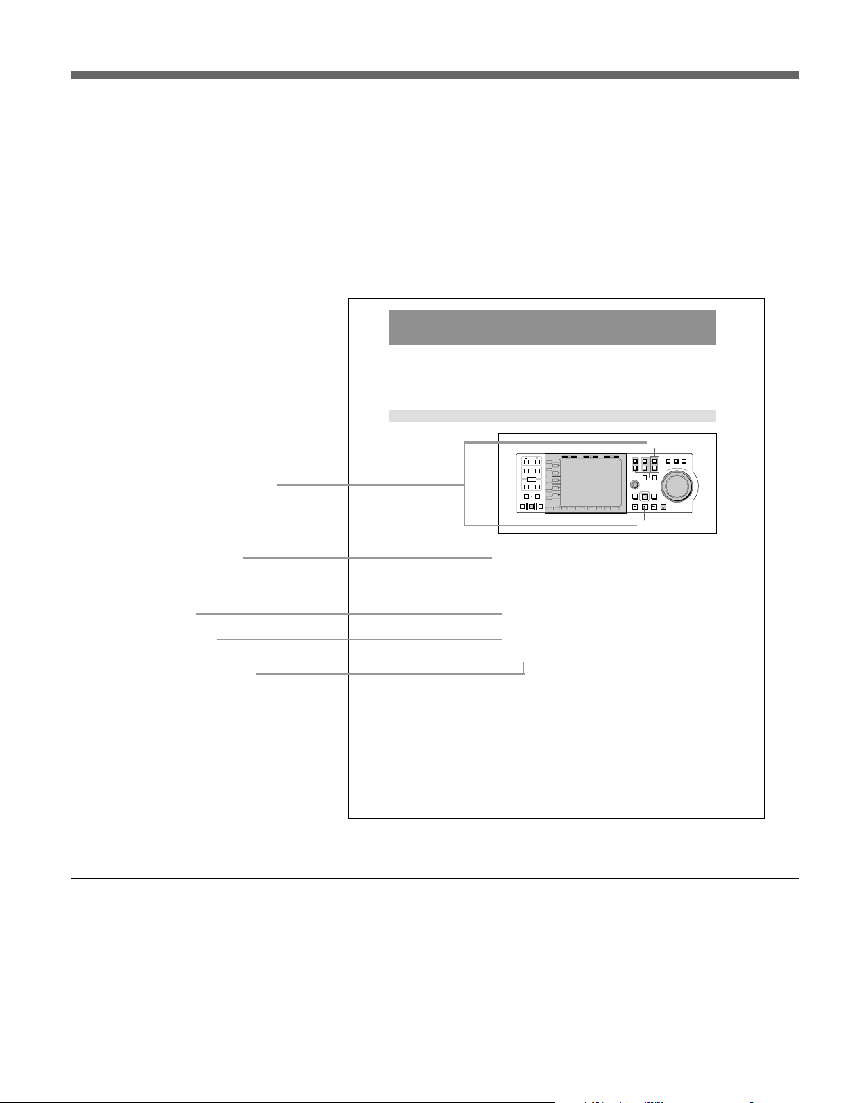
Using this manual
Descriptions of operating procedures
The numerals attached to buttons and switches in the illustrations refer to
corresponding step numbers in the operating procedure. Additionally, affected
switches and indicators which should be checked are indicated.
The first time a technical term appears it is defined in a footnote. Where
required, a cross-reference (in italics) shows the page in this manual or in
another manual where related information may be found.
5-2 Playback Operations
Available playback methods are as follows:
• Normal playback
• Variable speed playback, in jog, shuttle, or variable mode
5-2-1 Normal Playback
Numbers on switches etc. refer to
steps in procedure
Step number in procedure
Cross-reference
Results of a step and
related information
Description of step operation
5-2 (E)
Chapter 5 Playback
PB EE PB
L1
L2
L3
L4
L5
L6
L7
L8
L9
L10
L11
B1 B2 B3 B4 B5 B6 B7
MODE SHIFT
HOLD RESET TC/UB TIMER SEL
CONTROL
PREROLL EDIT
Normal speed playback
TRIM
IN OUT
AUDIO
ENTRY
OUT
IN
DELETE
DMC EDIT
MEMORY
AUTO EDIT
REVIEW
PREVIEW
1
Set the playback audio levels and video process values on the meter panel
of the MAV-555.
2
Select the playback port using the PORT SELECT button.
3
Select the material to be played back.
To select the material, in material mode carry out LOAD.
For details, see section 3-2, “Material Mode” (page 3-3).
4
Press the PLAY button.
Playback starts.
5
To stop playback, press the STOP button.
Example of procedure description
2
1
R1
P1
PORT SELECT
EXT
R2/
P2
2
P3
RECORDER
PLAYER
MULTI
REC
REW PLAY F. FWD STOP
4
SHUTTLE
JOG VAR
F
O
E
R
S
W
R
E
A
V
R
E
D
R
5
Related manuals
• In addition to this manual, an Installation Manual for this control panel is
supplied. It provides details of connections between the control panel and the
MAV-555, and of installing the control panel in the MAV-555. Be sure to
ask a Sony service person to carry out the installation of this control panel in
the MAV-555, and make the connections.
• Read this manual in conjunction with the manuals for the MAV-555.
About This Operation Manual 5 (E)
Page 8

Page 9

1-1 BKMA-505 Overview
The BKMA-505 is a dedicated control panel for use with the MAV-555
Multiaccess Video Disk Recorder. This unit provides a rich range of
functions to exploit the suitability of a hard disk as a nonlinear editing
device. The adoption of a large colour liquid crystal display enables
monitoring of record and play screens, and enables GUI operation.
MAV-555, MAV-555A, or MAV-555SS Ver. 2.32 is required in order
to use this version of BKMA-505.
1-2 Features
VTR-like user interface
For ease of use by users familiar with VTRs such as the DVW digital
Betacam recorders, a VTR-like panel layout is adopted. The MAV-555 can
be handled with the operability of a conventional VTR, and thus
introduction is smooth.
Chapter 1 Overview
Multi-port operation
Using this control panel, all of the internal ports of the MAV-555 can be
operated.
Use of 6.4-inch colour liquid crystal display
To display high-function information such as MAV-555 multi-port
operations reliably and clearly, the large (display area 130 x 97 mm) and
high-resolution (640 × 480 pixel) colour liquid crystal display is used. As
well as providing full information display functions including monitoring,
this also provides GUI operability.
Operations exploiting the features of a nonlinear device
Using this control panel, you can take full advantage of the MAV-555 hard
disk recorder’s capabilities as a non-linear device. The following operations
can be performed.
• Material data stored in the MAV-555 can be edited immediately,
regardless of the actual length of completed material. Further,
modifications can also be made immediately once editing is complete.
• Multiple material items can be recorded or played back simultaneously.
• Material can be edited as it is being recorded.
Direct input of numeric values
Timecode and user’s bit values can be directly entered as numeric values,
using function keys.
Chapter 1 Overview 1-1 (E)
Page 10

1-2 Features
Management functions for material
This control panel provides material management functions for the material
held on the MAV-555 (material mode). In material mode, as well as
displaying lists of material and detailed information on each item, functions
are provided that allow operations such as sorting, renaming, and deleting
items of material.
Edit Using EFFECT
When editing in Audio Channel mode, you can use material edited with the
Effect Transition feature of the BKMA-560 optional board installed in the
MAV-555.
Note
When operating from the BKMA-505, materials with patterns held on the
BKMA-561 cannot be specified.
A/V Data Transfer
When the BKMA-540 optional board is installed in the MAV-555, you can
transfer (send/receive) A/V data through an SDTI.
Time Difference Function
This function allows you to make reservations to record, preview, and play
material (Timer Rec/Play mode). In Timer Rec/Play mode, in addition to
being able to make various settings for Cue Sheet units, you can also sort
event lists, delete Cue Sheets, and register templates.
Simultaneous playback function for two materials
This function allows you to set the IN and OUT points, and the playback
port of two different pieces of material, such as a material that uses effects
and a key signal material. With a single operation, you can load and unload
the material and then simultaneously play back the two pieces of material
that you have set (Dual Play mode).
MAV-555A and MAV-555SS support
The BKMA-505 supports the MAV-555A and the MAV-555SS (which
supports Super Motion cameras). When using the MAV-555SS in SS
mode, it is possible to use -3/3 to 3/3 times playback speed with the
BKMA-505.
1-2 (E) Chapter 1 Overview
Page 11
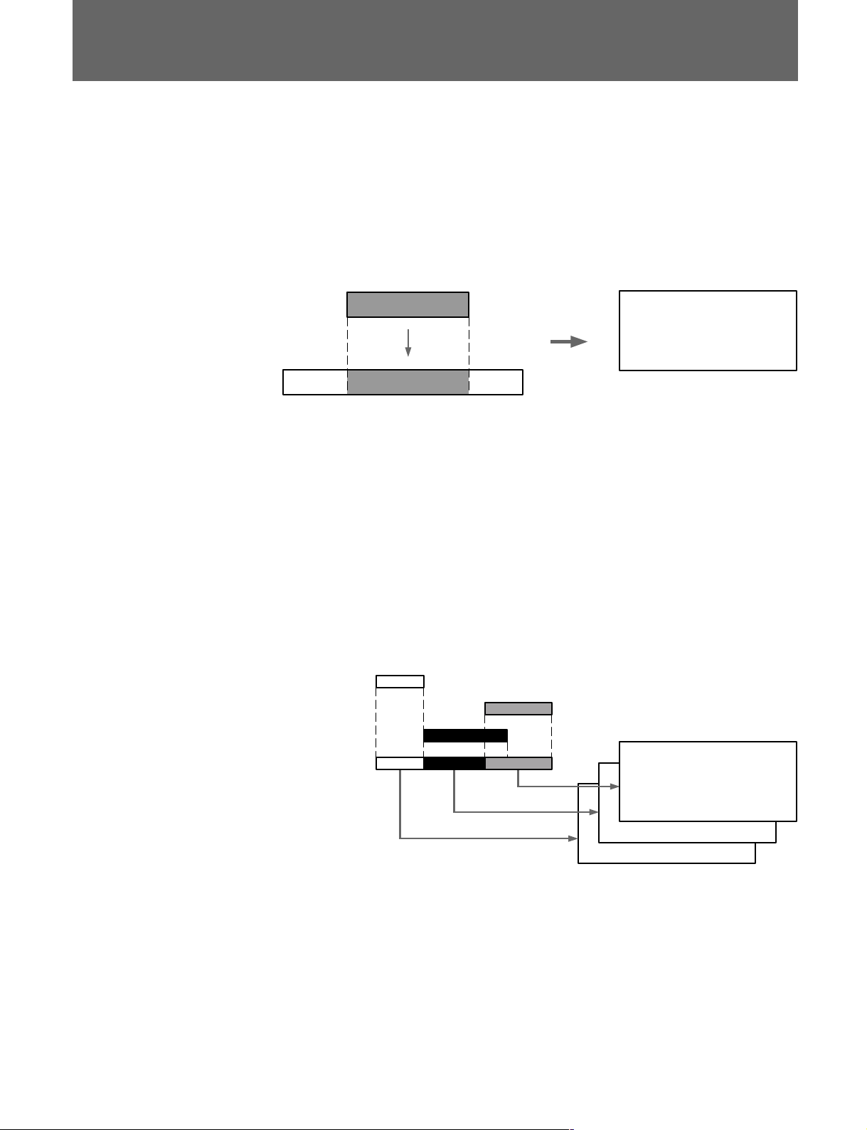
1-3 Overview of Edit Data Management
Source Materials
Program (Edit Data Pages)
SRC. OUT
SRC. IN
SRC. NAME
DST. OUT
DST. IN
PAGE NO.
3
1
2
Destination Material
One of the features of this control panel is its ability to manage multiple
edit points, allowing recordings to be modified (through retouch editing)
from the control panel. The control panel manages data equivalent to one
edit cut as one page. The following are recorded on one page: IN and OUT
points for original edit material (referred to below as source material), IN
and OUT points for edit destination material (referred to below as
destination material), and the source material name and page number.
SRC. IN SRC. OUT
Source
Destination
DST. IN
SRC. NAME
SRC. IN
SRC. OUT
Edit Data Page
DST. OUT
PAGE NO.
DST. IN
DST. OUT
A stack of pages for the same destination material is called a program. Page
numbers indicate the sequence of edit cuts in the destination material. By
tracing the contents of pages according to page number sequence, you can
reproduce the contents of the destination material from the beginning.
Because one page corresponds to an edit cut in the destination material, the
page number and overlap section of edit point data may change after
editing.
In the following diagram, the source material numbers indicate the editing
sequence, but the pages are arranged in the time sequence of the destination
material.
Once editing is complete, you can immediately call up pages for
modification. There is no need to play through the entire recording, as is
the case with ordinary linear editing. The control panel can only manage
one program at a time. A program is effective as long as a page is being
created or edited through continuous editing for a single destination
material. In other words, if you switch destination materials, the program
for the destination material that was being edited is cleared.
Chapter 1 Overview 1-3 (E)
Page 12

1-4 (E) Chapter 1 Overview
Page 13
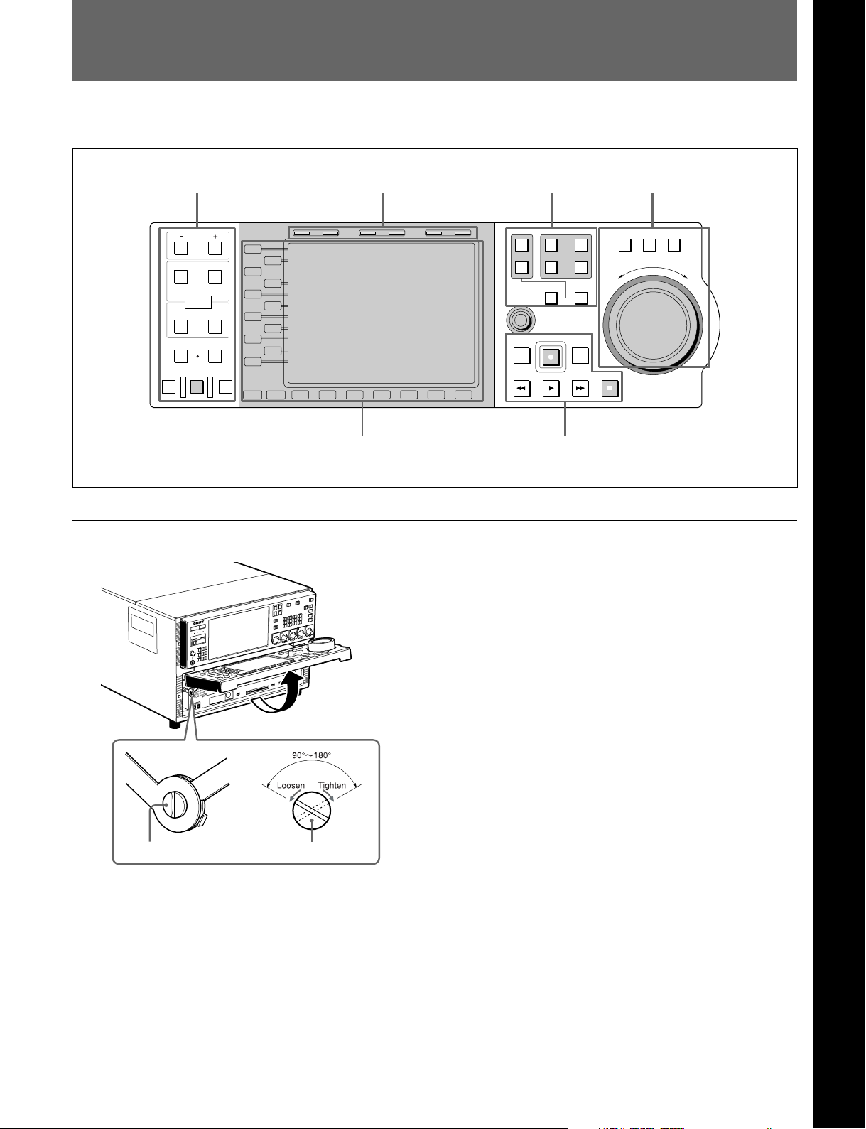
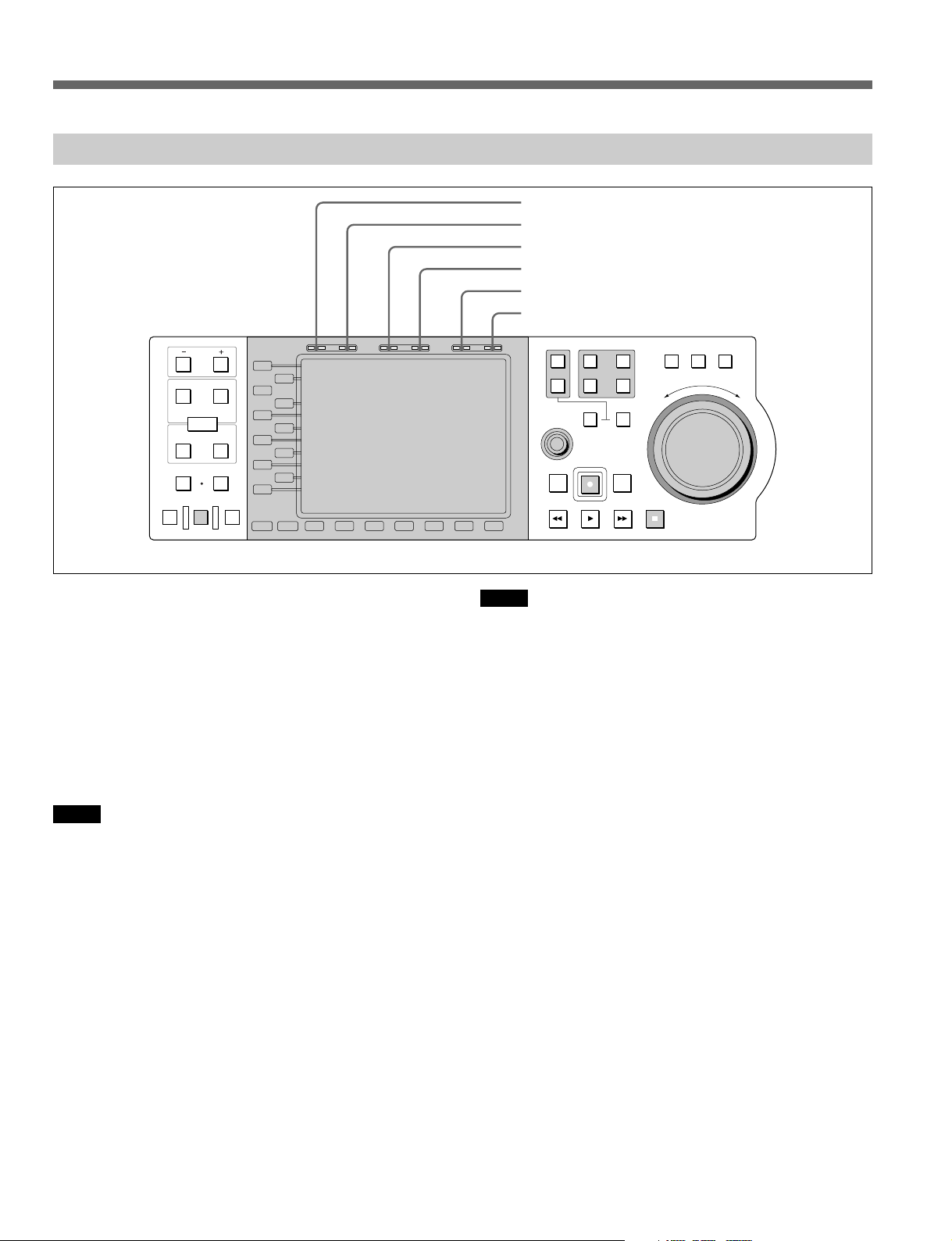
2-1 Front Side of Panel
This section describes the front panel divided into six sections, by function.
Editing operation section Timecode section Port select section Search operation section
Chapter 2 Name and Functions of Parts
HOLD RESET TC/UB TIMER SEL
PREVIEW
IN OUT
AUDIO
ENTRY
IN
DMC EDIT
MEMORY
AUTO EDIT
PB EE PB
TRIM
DELETE
OUT
REVIEW
L1
L2
L3
L4
L5
L6
L7
L8
L9
L10
L11
MODE SHIFT
B1 B2 B3 B4 B5 B6 B7
Function operation section and display Transport control section
Adjustment the stiffness of the control panel
SHUTTLE
1
R1
P1
PORT SELECT
EXT
R2/
2
MULTI
CONTROL
PREROLL EDIT
REW PLAY F. FWD STOP
PLAYER
REC
P2
P3
RECORDER
JOG VAR
F
E
S
R
E
V
E
R
O
R
W
A
R
D
Adjustment screws on both sides of the MAV-555 can
be tightened or loosened to change the stiffness of
the control panel as it opens and closes.
Turning the screw clockwise tightens the panel, and
turning it counterclockwise loosens it. The screw
rotates between 90° to 180°. Adjust as required.
However, please avoid opening and closing the control
panel when the screw is turned fully clockwise.
Adjustment screw Adjustment screw
Chapter 2 Name and Functions of Parts 2-1 (E)
Page 14
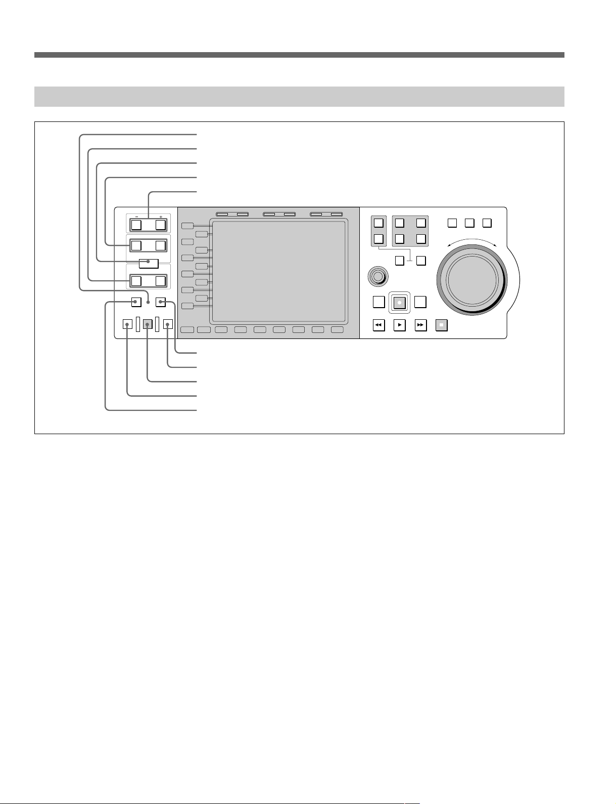
2-1 Front Side of Panel
2-1-1 Editing Operation Section
1 MEMORY indicator
2 IN/OUT buttons
3 ENTRY button
4 AUDIO IN/OUT buttons
5 TRIM buttons
PB EE PB
PREVIEW
IN OUT
AUDIO
ENTRY
IN
DMC EDIT
MEMORY
AUTO EDIT
TRIM
DELETE
OUT
REVIEW
L1
L2
L3
L4
L5
L6
L7
L8
L9
L10
L11
MODE SHIFT
B1 B2 B3 B4 B5 B6 B7
HOLD RESET TC/UB TIMER SEL
1
R1
P1
PORT SELECT
EXT
R2/
2
MULTI
CONTROL
PREROLL EDIT
REW PLAY F. FWD STOP
P3
PLAYER
REC
P2
RECORDER
SHUTTLE
JOG VAR
F
E
S
R
E
V
E
R
O
R
W
A
R
D
6 DELETE button
7 REVIEW button
8 AUTO EDIT button
9 PREVIEW button
0 DMC EDIT button
1 MEMORY indicator
In DMC Editing mode, this indicator flashes when the
interval between the IN and OUT points is played back
at a variable speed using the PREVIEW button. If the
OUT point is exceeded, the indicator lights.
2 IN/OUT buttons
Hold down this button and press the ENTRY button to
set the IN and OUT points. The button pressed lights
when the setting is made.
If you press this button after the points are set, the
values for IN and OUT points appear in the time data
display area.
3 ENTRY button
This button selects edit points.
Press this button while holding down one of the IN or
OUT buttons. Pressed together with the IN or OUT
button, it selects the IN or OUT point. Pressed together
with the AUDIO IN or AUDIO OUT button, it selects
the AUDIO IN or AUDIO OUT point. The button
pressed lights when the setting is made.
4 AUDIO IN/OUT buttons
This button sets AUDIO IN and OUT points separately
from those set for images. Hold down the ENTRY
button and press one of these buttons to set the audio IN
or OUT point. The button pressed lights when the
setting is made. If you press this button after the points
are set, the numeric values for the audio IN and OUT
points appear in the time data display area.
5 TRIM buttons
This button modifies selected edit points a frame at a
time. Holding down the IN, OUT, AUDIO IN, or
AUDIO OUT button, press either of the two TRIM
buttons. The screen jumps forward one frame if you
press the + button, and jumps back one frame if you
press the - button.
6 DELETE button
This button deletes selected edit points.
When you press either of the previously set (lit) IN or
OUT buttons together with this button, that edit point is
deleted and the button goes out or flashes. If the buttons
you pressed simultaneously flashes, you must specify
the edit point to be deleted.
2-2 (E) Chapter 2 Name and Functions of Parts
Page 15

7 REVIEW button
If you press this button after editing an interval, you can
view playback of the edited interval on the monitor.
8 AUTO EDIT button
Press this button after selecting an edit point to start auto
edit. If you press this button when no IN point is
selected, the time data at the time of pressing this button
is set as the IN point, and abbreviated editing starts.
9 PREVIEW button
After edit points have been set, this button allows you to
output the edit results screen on the monitor before
doing any actual edit recording. Pressing this button
does not start editing. If you press this button when no
IN point is selected, the time data at the time of pressing
this button is selected as the IN point, and preview runs.
0 DMC EDIT button
Press this button when you want to perform DMC
Editing (Dynamic Motion Control) and it lights. If you
hold down the button and turn the search dial, the initial
speed of the IN point is set. Furthermore, if you press
the button while it is lit, you can reconfirm the initial
speed set of the IN point.
Chapter 2 Name and Functions of Parts 2-3 (E)
Page 16
2-1 Front Side of Panel
2-1-2 Port Select Section
1 PORT SELECT buttons
PREVIEW
IN OUT
AUDIO
ENTRY
IN
DMC EDIT
MEMORY
AUTO EDIT
PB EE PB
TRIM
DELETE
OUT
REVIEW
L1
L2
L3
L4
L5
L6
L7
L8
L9
L10
L11
MODE SHIFT
B1 B2 B3 B4 B5 B6 B7
HOLD RESET TC/UB TIMER SEL
1 PORT SELECT buttons
P1, P2, R1, and R2/P3 buttons:
These select the internal port of the MAV-555 to which
operations on the control panel apply.
The button for the selected port lights (port P1 in the
following figure).
1
R1
P1
PORT SELECT
EXT
R2/
2
PLAYER
P2
P3
RECORDER
• When the MAV-555 is used in the 1 input/1 output
configuration, only P1 and R1 can be used.
• When the MAV-555 is used in the 2 input/2 output
configuration, P1 and P2 are playback ports, and R1
and R2 are recording ports.
Note
This button can be used irrespective of MAV-555 port
remote settings.
EXT1, EXT2 buttons:
These buttons select for operation the device connected
to the remote connector (IN/OUT1 (VTR), IN/OUT2
(VTR)) of the connector panel on the MAV-555. Each
button EXT1, EXT2 corresponds to the device
connected to IN/OUT1 (VTR), IN/OUT2 (VTR). When
you press a button, the button lights to indicate that the
port corresponding to that button is selected. If you
select EXT1 then R1 Port is displayed in the monitor,
and if you select EXT2 then R2 Port is displayed in the
monitor.
SHUTTLE
1
R1
P1
PORT SELECT
EXT
R2/
2
MULTI
CONTROL
PREROLL EDIT
REW PLAY F. FWD STOP
P3
PLAYER
REC
P2
RECORDER
JOG VAR
F
E
S
R
E
V
E
R
O
R
W
A
R
D
2 RECORDER button
3 PLAYER button
However, even when connected to the remote jack of the
MAV-555 connector panel if the connected device is set
for LOCAL, it cannot be selected.
The configuration and operation modes that can be
selected with the EXT1, EXT2 buttons are shown in the
table below.
1 input 2 input 1 input 3 input
/1 output /2 output /3 output /1 output
Panel EXT1 O EXT1 O EXT1 O EXT1 O
EXT2 × EXT2 O EXT2 × EXT2 f
DTR + Panel EXT1 f EXT1 f EXT1 f EXT1 f
EXT2 × EXT2 O EXT2 × EXT2 f
DTR + DTR × f ××
BVE Editor ××××
O Selectable
× Not selectable
f Not selectable during editing
Notes
• EXT1, EXT2 cannot be selected as the RECORDER.
• When you are using a 1 input/3 output or 3 input/
1 output configuration, if item 317 PANEL MODE
RECORDER PORT on the Expansion menu of the
MAV-555 is not set to R1P1, EXT1 cannot be selected
as the PLAYER.
For more details about how to use the MAV-555 Expansion
menu, see “3-4-3 Contents of the Expansion Menu” in the
MAV-555 Operation Manual.
2-4 (E) Chapter 2 Name and Functions of Parts
Page 17
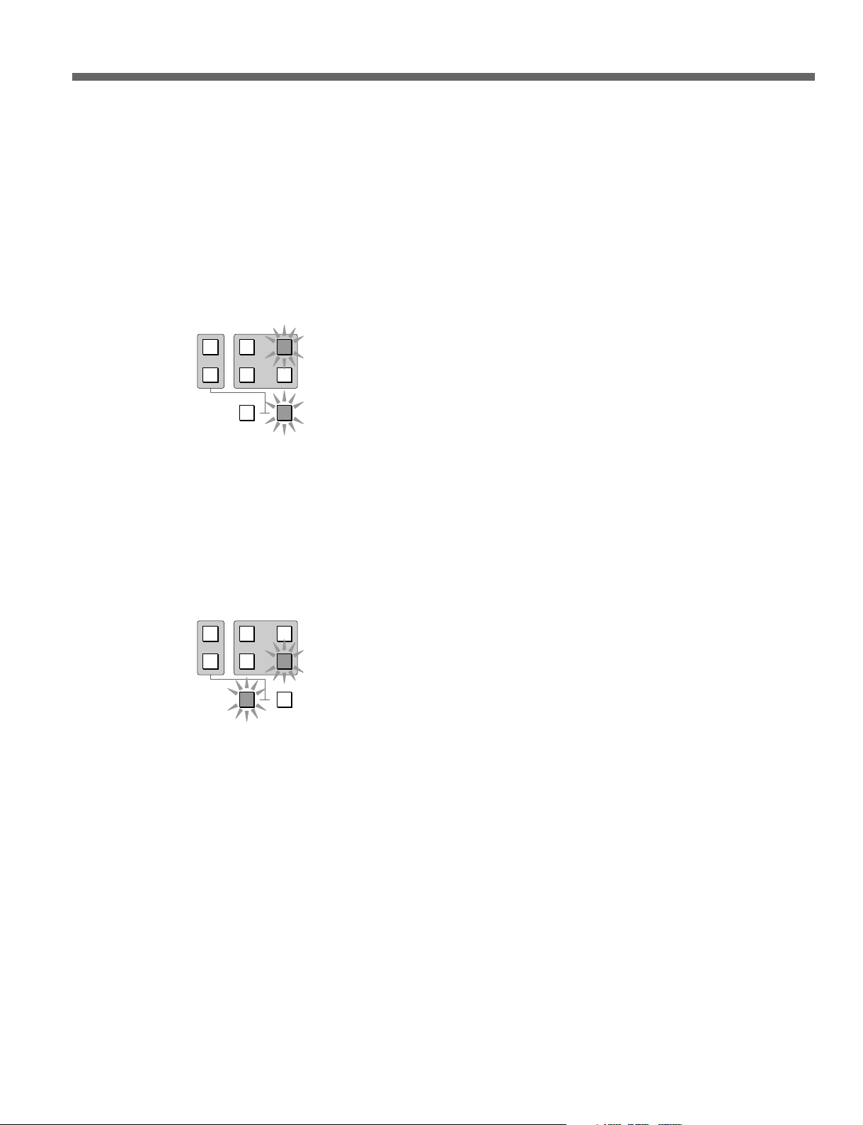
2 RECORDER button
This button selects the port (the RECORDER port) used
as the recorder during editing. Pressing this button
automatically selects the Recorder port according to the
setting of the 317 “PANEL MODE RECORDER
PORT” item in the MAV-555 Basic menu, and the
selected port button and RECORDER button both light.
For example, if the MAV-555 is set for R1P1, P1 is
specified as the RECORDER port and the panel lights as
shown in the following figure after you press the
RECORDER button.
1
R1
P1
EXT
PORT SELECT
R2/
2
PLAYER
P2
P3
RECORDER
3 PLAYER button
This button selects the port used as the player during
editing (the PLAYER port). You can switch the
PLAYER port by pressing this button simultaneously
with any one of the PORT SELECT buttons. For
example, if you press this button together with the P2
button, the lamps corresponding to these buttons light as
shown in the following figure and P2 is selected as the
PLAYER port.
1
R1
P1
EXT
PORT SELECT
R2/
2
PLAYER
P2
P3
RECORDER
Chapter 2 Name and Functions of Parts 2-5 (E)
Page 18
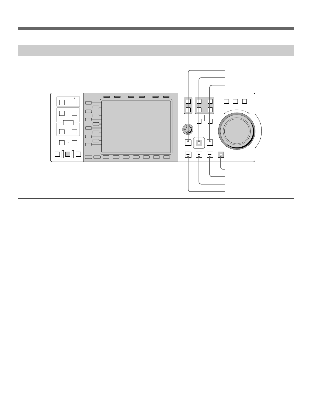
2-1 Front Side of Panel
2-1-3 Transport Control Section
PB EE PB
PREVIEW
IN OUT
AUDIO
ENTRY
IN
DMC EDIT
MEMORY
AUTO EDIT
TRIM
DELETE
OUT
REVIEW
L1
L2
L3
L4
L5
L6
L7
L8
L9
L10
L11
MODE SHIFT
B1 B2 B3 B4 B5 B6 B7
HOLD RESET TC/UB TIMER SEL
1
R1
P1
PORT SELECT
EXT
R2/
2
MULTI
CONTROL
PREROLL EDIT
REW PLAY F. FWD STOP
P3
PLAYER
REC
P2
RECORDER
1 PREROLL button
2 REC button
3 EDIT button
SHUTTLE
JOG VAR
E
S
R
E
V
E
R
4 STOP button
5 F FWD button
6 PLAY button
7 REW button
F
O
R
W
A
R
D
1 PREROLL button
Press this button to cue up to preroll points (the point
preceding the IN point preroll time) in material on the
hard disk.
By pressing this button simultaneously with the IN or
OUT button, you can jump to the corresponding edit
point.
2 REC (record) button
Hold down this button and press the PLAY button to
start recording.
3 EDIT button
To enter Recorder Edit mode to perform editing
operations such as editing voice-overs, press this button
while holding down the RECORDER button. The
RECORDER button and the R1 and P1 buttons (or the
R2 and P2 buttons) light. The RECORDER port is
automatically selected depending on the port selected on
the MAV-555 expansion menu 317 PANEL MODE
RECORDER PORT.
You can also press the B1 (Load) key while pressing
this button to load a material in a currently unused
recorder port.
4 STOP button
Press this button to stop playback or recording. This
stopped state is also referred to as “stop mode.”
If extension menu item 120 “OUTPUT REF LOCK” on
the MAV-555 is set to R1 or R2, and no signal is input
to the input connector, or it is set to REF and no external
reference signal is input to the REFERENCE input
connector (or is not synchronized to the input video
signal), the STOP button flashes.
5 F. FWD (fast forward) button
Press this button to fast forward.
By pressing this button while pressing and holding the
PREROLL button, you can cue up to the end of
material.
6 PLAY button
Press this button to start playback.
7 REW (rewind) button
Press this button to rewind.
By pressing this button while pressing and holding the
PREROLL button, you can cue up to the beginning of
material.
2-6 (E) Chapter 2 Name and Functions of Parts
Page 19
2-1-4 Search Operation Section
PB EE PB
PREVIEW
IN OUT
AUDIO
ENTRY
IN
DMC EDIT
MEMORY
AUTO EDIT
TRIM
DELETE
OUT
REVIEW
L1
L2
L3
L4
L5
L6
L7
L8
L9
L10
L11
MODE SHIFT
B1 B2 B3 B4 B5 B6 B7
HOLD RESET TC/UB TIMER SEL
1 VAR button
2 JOG button
3 SHUTTLE button
1
R1
PORT SELECT
EXT
R2/
2
P3
PLAYER
MULTI
CONTROL
REC
PREROLL EDIT
REW PLAY F. FWD STOP
4 Search dial
P1
P2
RECORDER
SHUTTLE
JOG VAR
F
E
S
R
E
V
E
R
O
R
W
A
R
D
1 VAR (variable) button
Press this button, turning it on, to play back in variable
mode using the search dial.
For details of variable mode, see the item for the search dial
(4).
2 JOG button
Press this button, turning it on, to play back in jog mode
using the search dial.
For details of jog mode, see the item for the search dial (4).
3 SHUTTLE button
Press this button, turning it on, to play back in shuttle
mode using the search dial.
For details of shuttle mode, see the item for the search dial
(4).
4 Search dial
This can be used for variable speed playback. Turn
clockwise for forwards playback, and counterclockwise
for reverse playback. Pressing the search dial toggles
between shuttle and jog modes or variable and jog
modes.
The operation of the search dial in each of shuttle, jog,
and variable modes is shown in the following table.
Playback mode
Shuttle mode
Jog mode
Variable mode
Operation and function
Press the SHUTTLE button, turning the
SHUTTLE button on, then turn the search
dial. Playback occurs at a speed determined
by the angular position of the search dial.
The range of playback speeds is as follows.
The range of playback speeds can be set
between 8 and 500 times normal speed in
MAV-555 extension menu 106 (MAXIMUM
SHUTTLE SPEED). However, the external
device selection remains in effect when an
external device is selected.
The search dial has notches at the still
image position and at +8 and -8 times
normal speed.
Press the JOG button, turning the JOG
button on, then turn the search dial.
Playback occurs at a speed determined by
the rotation rate of the search dial. The
range of playback speeds is from –4 to +4
times normal speed. The Search dial does
not have notches.
Press the VAR button, turning the VAR
button on, then turn the search dial.
Playback occurs noiselessly at a speed
determined by the angular position of the
search dial, and you can control the
playback speed finely within the range –1 to
+1 times normal speed. In the 1 input/
3 output configuration, the range of the
playback speed is ±2x normal speed.
However, the external device selection
remains in effect when an external device is
selected.
The search dial has notches at the still
image and ±1 speed positions.
Note that immediately after powering on the MAV-555
connected to this control panel, you should first return
the search dial to its central position.
Chapter 2 Name and Functions of Parts 2-7 (E)
Page 20
2-1 Front Side of Panel
2-1-5 Timecode Section
1 PB.EE button
2 PB button
3 HOLD button
4 RESET button
5 TC/UB button
6 TIMER SEL button
HOLD RESET TC/UB TIMER SEL
PREVIEW
IN OUT
AUDIO
ENTRY
IN
DMC EDIT
MEMORY
AUTO EDIT
PB EE PB
TRIM
DELETE
OUT
REVIEW
L1
L2
L3
L4
L5
L6
L7
L8
L9
L10
L11
MODE SHIFT
B1 B2 B3 B4 B5 B6 B7
1 PB.EE (playback/E-E) button
Pressing this button outputs the VIDEO or AUDIO input
signals on the monitor, according to the conditions set in
the MAV-555 expansion menu 108 AUTO EE
SELECT.
2 PB (playback) button
Pressing this button outputs the VIDEO or AUDIO
playback signals on the monitor.
Notes
• The above operations 1 and 2 have the same settings as
the MAV-555 basic menus 013 and 014 PB/EE
SELECT. Accordingly, any condition settings made
hereafter are applied.
• Effective with the P1, P2, and P3 ports. However, the
P3 port is only supported by the MAV-555A and
MAV-555SS.
3 HOLD button
Pressing this button displays a time data entry dialog
box on the liquid crystal display, and stops the advance
of values in the time counter display. Press once more to
clear the time data entry dialog box, and return the time
counter display to showing the currently read in values.
To set time data values, first press this button to stop the
advance of the data.
SHUTTLE
1
R1
P1
PORT SELECT
EXT
R2/
2
MULTI
CONTROL
PREROLL EDIT
REW PLAY F. FWD STOP
P3
PLAYER
REC
P2
RECORDER
JOG VAR
F
E
S
R
E
V
E
R
O
R
W
A
R
D
Notes
• The PORT SELECT buttons do not work from the
control panel while the HOLD button is being pressed.
If a port selection is changed from a controller other
than the control panel, such as the meter panel, the time
data input dialog box closes.
• When using Timer2, operation of the HOLD button is
disabled.
4 RESET button
When time data is displayed as Timer1 in the liquid
crystal display, pressing this button resets the time data.
Pressing this button while the time data dialog box is
displayed enters a zero in every digit.
5 TC/UB (time code/user’s bit) button
Pressing this button displays the user’s bit (UB) inserted
in the timecode on the currently selected port on the
liquid crystal display. If the TIMER SEL displayed is
LTC or VITC, the corresponding LTC or VITC user’s
bit are displayed.
When the user’s bit are displayed, pressing the TC/UB
button once more returns to the normal timecode (that is
time data other than user’s bit) display.
2-8 (E) Chapter 2 Name and Functions of Parts
Page 21

6 TIMER SEL (time data) button
This button selects the type of time data displayed on the
LCD. With an internal port currently selected (P1, P2,
R1, or R2/P3 lit) and with normal time data displayed
(LTC, VITC, TM1, or TM2), pressing the TIMER SEL
button cycles through the sequence: LTC → VITC →
TM1 → TM2 → LTC ... .
If the user’s bit is displayed, pressing the TIMER SEL
button toggles between the LTC user’s bit and VITC
user’s bit.
If EXT1 or EXT2 is selected (EXT1 or EXT2 button lit),
normal time data for only LTC (or VITC) and TM1 is
displayed. Further, when normal time data (LTC (or
VITC), TM1) is displayed, pressing the TIMER SEL
button cycles through the sequence LTC (or VITC) →
TM1 → LTC (or VITC) → ... . With EXT1 or EXT2
selected and with the user bit displayed, the TIMER
SELECT button is disabled.
Chapter 2 Name and Functions of Parts 2-9 (E)
Page 22
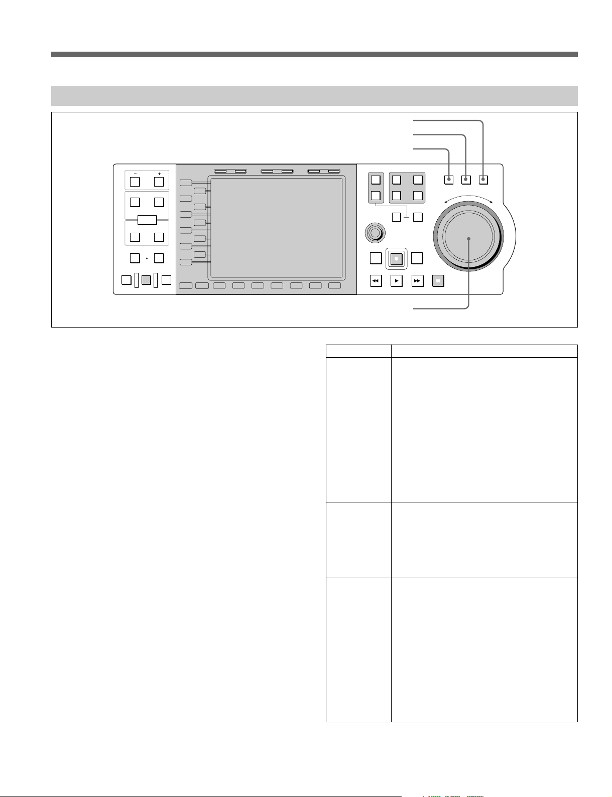
2-1 Front Side of Panel
2-1-6 Function Operation Section and Display
1 Function (L1 to L11) buttons
2 Liquid crystal display
HOLD RESET TC/UB TIMER SEL
3
Function (B1 to B7) buttons
PREVIEW
IN OUT
AUDIO
ENTRY
IN
DMC EDIT
MEMORY
AUTO EDIT
PB EE PB
TRIM
DELETE
OUT
REVIEW
L1
L2
L3
L4
L5
L6
L7
L8
L9
L10
L11
MODE SHIFT
B1 B2 B3 B4 B5 B6 B7
4 SHIFT button
5 MODE button
6 MULTI CONTROL knob
1 Function (L1 to L11) buttons
Each of these buttons is for executing the function
currently indicated to the right of the button (in the
function button display area). If nothing is currently
indicated for the button or the display is dimmed, the
button has no effect.
2 Liquid crystal display
The liquid crystal display in this control panel is divided
into four areas as shown in the following figure.
Function button function display area (L1 to L11)
Current port area
SHUTTLE
1
R1
P1
PORT SELECT
EXT
R2/
2
MULTI
CONTROL
PREROLL EDIT
REW PLAY F. FWD STOP
P3
PLAYER
REC
P2
RECORDER
JOG VAR
F
E
S
R
E
V
E
R
O
R
W
A
R
D
Current port area
This shows the following information specific to the
currently selected port:
• Port name
• Name of material
• Time data
• Timecode type, time data type (indication corresponding
to TC/UB button and TIMER SEL button settings)
• Operation status (transport status, and shuttle/jog/variable
mode status)
• REMOTE state
• Picture quality
• Position status
For details of the items shown in the current port area, see
Section 3-1, “Common Display Items (Current Port Area)” (page
3-1).
Function button function display
area (B1 to B7)
Operating mode information
display area
2-10 (E) Chapter 2 Name and Functions of Parts
Page 23
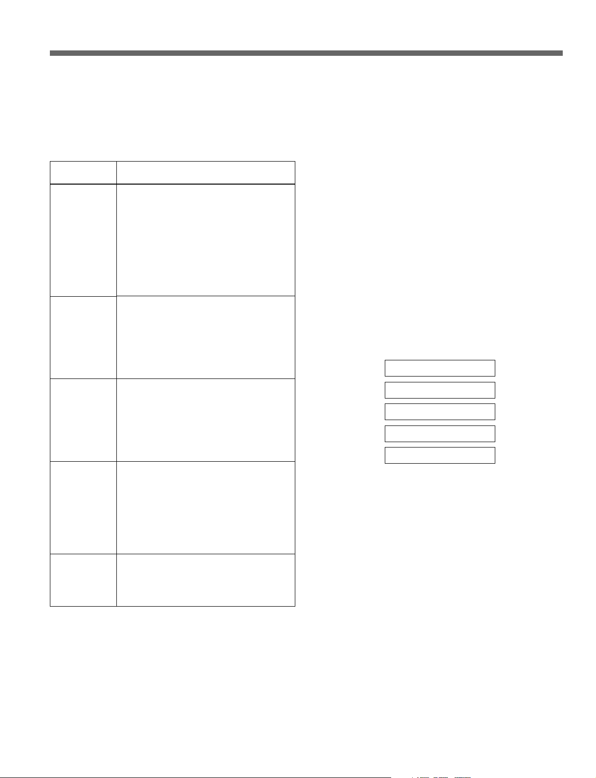
Operating mode information display area
This displays information for the current operating
mode specified using the MODE button (5) and
function buttons (1 and 3). The operating modes
and the information displayed in each mode are listed
in the following table.
Operating
mode
MATERIAL
(Material
mode)
EDIT
(Edit mode)
Timer Rec/Play
(Timer Rec/
Play mode)
Dual Play
(Dual Play
mode)
CP SETUP
(CP setup
mode)
Description of mode and information
shown
This mode is for material management
functions, such as displaying a list of the
material held on the MAV-555 hard disks,
searching, renaming, deleting, assigning to
ports, and canceling assignments. In this
mode, the following information is displayed.
• List of material
• Indication of active material
• Detailed information about specified items
of material
• Monitor screen
This mode is for carrying out editing.
In this mode, the following information is
displayed.
• Name of material being edited
• Stamp pictures of IN and OUT points on
material being edited
• List of timecodes and durations for
specified IN and OUT points
This mode allows you to carry out time
difference functions. Material recordings,
previews, and plays referred to as timer
events. The following information is
displayed for timer events.
• Event list display
• Specific event detailed information display
• Monitor screen
This mode is for playing back two different
pieces of material simultaneously. Material
settings are referred to as aliases. The
following information is displayed for
aliases.
• Alias list display
• Specific alias list detailed information
display, or specified port monitor screen
• Monitor screen
This mode is for making control panel
operation settings, such as the edit point
input method, LCD brightness, and date
style. Information displayed varies according
to items being set.
In addition to the operating mode display, various dialog
boxes appear in this area as operations require it.
3 Function (B1 to B7) buttons
Each of these buttons is for executing the function
currently indicated above the button (in the function
button display area). If nothing is currently indicated
above the button or the display is dimmed, the button
has no effect.
4 SHIFT button
While this button is held down, the functions currently
assigned to the function buttons change. While the
function assignment is changed, you can check in the
function button function display areas. Whether this
button functions or not is a function of the current
operating mode and status.
5 MODE button
The operating modes of the control panel are the
Material mode (MATERIAL), the Edit Mode (EDIT),
the Timer Rec/Play mode (Timer Rec/Play), the Dual
Play mode (Dual Play), and the CP setup mode (CP
SETUP). Press the MODE button to select the modes.
Material mode
Edit mode
Timer Rec/Play mode
Dual Play mode
CP setup mode
Pressing this button displays the names of the modes in
the function button function display area, and you can
then select the operating mode using the function
buttons (1).
For details of the control panel operating modes, see the item
for the liquid crystal display (2), “Operating mode
information display area.”
6 MULTI (multiple) CONTROL knob
This is used for cursor movement in the GUI displayed
on the liquid crystal display, and for inputting characters
for changing the names of materials
It can also be used to increase or decrease numeric
values input during edit operations (e.g., trimming).
Function button function display areas
These areas display the currently assigned functions
of the function buttons (1 and 3) to the left of and
below the liquid crystal display. Use the MODE
button (5) and SHIFT button (4) to change the
displays.
Chapter 2 Name and Functions of Parts 2-11 (E)
Page 24

2-1 Front Side of Panel
Note on the liquid crystal display
The liquid crystal display fitted to this unit is manufactured with
high precision technology, giving a functioning pixel ratio of at
least 99.99%. Thus a very small proportion of pixels (at most
0.01%) may be “stuck”, constantly on or constantly off. In
addition, over a long period of use, because of the physical
characteristics of the liquid crystal display, such “stuck” pixels may
appear spontaneously.
These problems have been kept to the absolute minimum, but are an
unavoidable characteristic of liquid crystal technology.
2-12 (E) Chapter 2 Name and Functions of Parts
Page 25

2-2 Rear Side of Panel
On the rear panel of the control panel is a dedicated port for connection to the
MAV-555. Using the cable supplied with the control panel, connect this port
to the CONTROL PANEL port at the bottom of the system set up panel on the
MAV-555. For details of the method of installing the control panel in the
MAV-555 and of connection, refer to the supplied Installation Manual.
Note
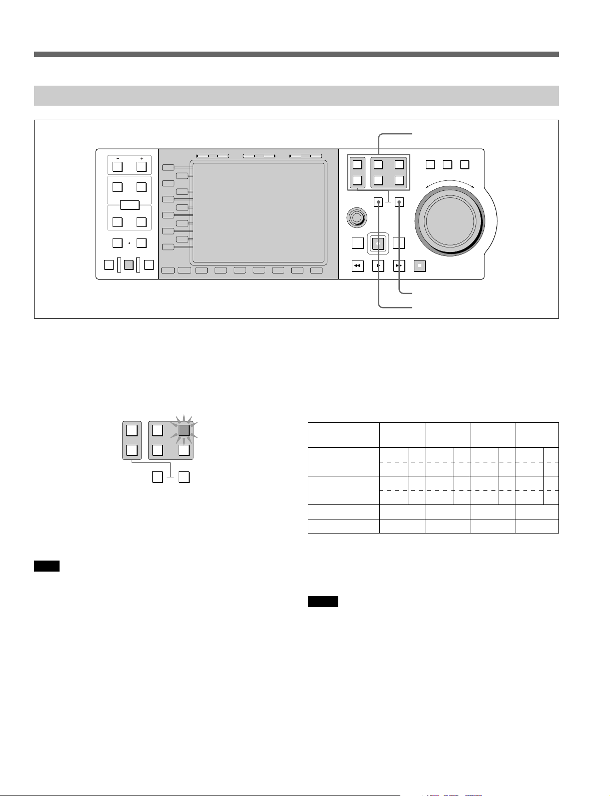
Be sure to ask a Sony service person to carry out the installation of this control
panel in the MAV-555, and make the connections.
Chapter 2 Name and Functions of Parts 2-13 (E)
Page 26

Page 27
3-1 Common Display Items (Current Port Area)
This section describes display items common to the operating modes
(material mode and setup mode) of the control panel, in the current port
area of the liquid crystal display.
3-1-1 Overview of Current Port Area
The current port area displays the same information regardless of the
operating mode of the control panel, and principally shows the operating
status of the port to which operations currently apply. Additionally it shows
important information about the system as a whole.
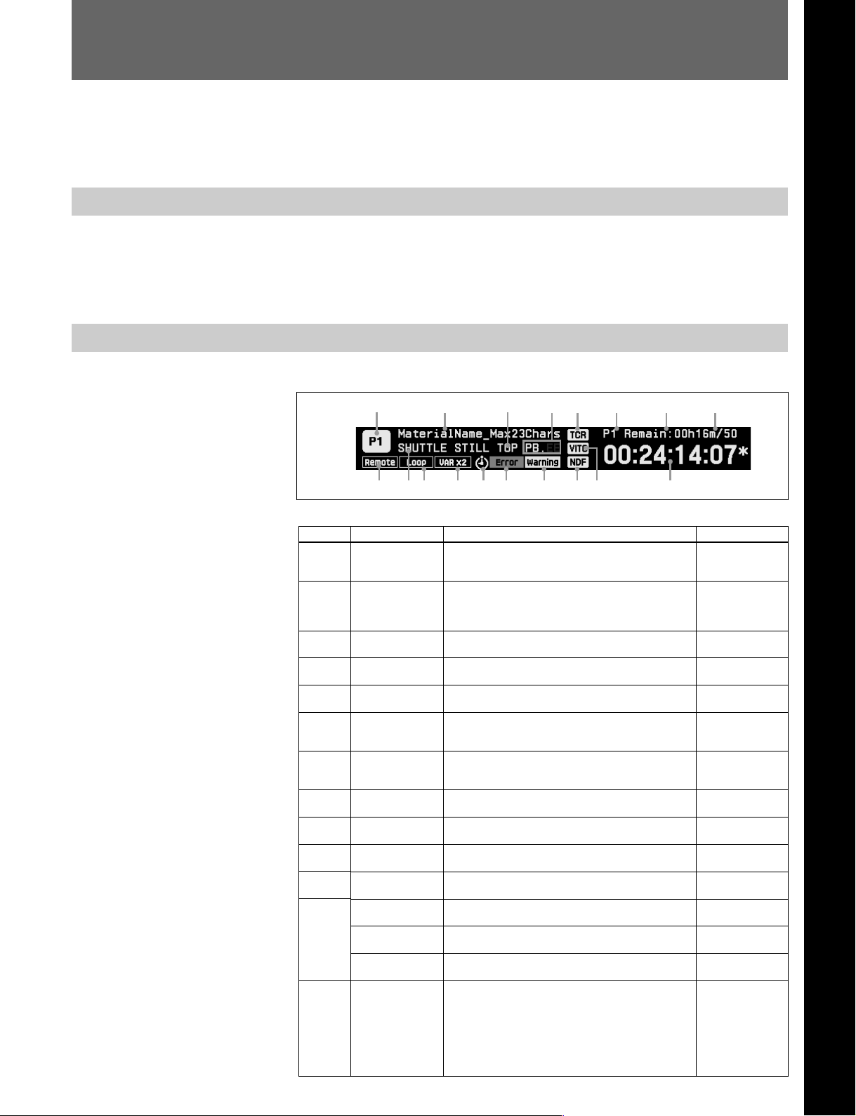
3-1-2 Display Items
The items displayed in the current port area are as follows.
Chapter 3 Operating Modes
Number
1
2
3
4
5
6
7
8
9
0
qa
qs
qd
9 0 qa
Name
Current port
Material name
Position status
PB.EE
Timecode type
Remain mode
Remain time
Picture quality
Remote/local
Current status
Loop mode
Rec Inhibit
Feed
Variable mode
Timer event icon
3
qs
qd
qf qg qh qj qk
Example of current port area display
Information displayed
This is the name of the port to which operations
currently apply.
This is the name of the material currently assigned
to the current port.
Indicates the position of the current port’s material.
Displays the current PB.EE settings and the monitor
status.
This shows whether the time data is TC or UB, and
whether a TCG value or a read-out value.
Specifies whether to indicate the remaining system
disk capacity or the remaining time of the material
assigned to port.
Displays the remaining time of material assigned to
port currently the subject of operation or the
remaining system disk capacity.
Displays the picture quality of the material assigned
to the port that is currently the subject of operation.
Indicates whether the current port is in the remote
state or the local state.
This is the current status of the current port’s
material.
Indicates the loop mode of the current port’s
material.
Lights when recording on the current port is
inhibited by the MAV-555 or external device setup.
Lights when material is loaded using A/V data
transfer through an SDTI.
Lights when material is loaded at 2× variable speed
when in 1 input/3 output configuration.
Displays the status of timer events.
541 267 8
Chapter 3 Operating Modes 3-1 (E)
Displays
P1, P2, R1, R2,
RP, EXT1, EXT2,
etc.
Character string
made up of
English numerals
and symbols
TOP, END, EOT
(no display)
PB.EE, PB,
(no display)
TCR, TCG, UBR,
UBG, T*R, U*R
Sys Remain,
P1 Remain,
R1 Remain etc.
**h**m
50, 40, 30
Remote,
(no display)
PLAY, REC, SEND,
RECEIVE, etc.
Loop, (no display)
Rec inhibit,
(no display)
Feed,
(no display)
Var ×2,
(no display)
Red: error event
Yellow: warning
event
White: standby
event
Flashes white:
operation event
(no display)
Page 28

3-1 Common Display Items (Current Port Area)
Number
qf
qg
qh
qj
qk
Name
Error
Warning
Drop-frame mode
Time data type
Time data
Information displayed
Appears when an error occurs in the MAV-555.
Appears when a warning occurs in the MAV-555.
Indicates the drop-frame mode of the time data for
the current port.
This is the time data type selected by the TIMER
SEL button.
Shows the specified time data.
Displays
ERROR,
(no display)
WARNING,
(no display)
DF, NDF
LTC, VITC, TM1,
TM2
Time data
Note
When material is loaded to the port that is currently the subject of operation,
the displayed contents of Remain mode indicate the amount of remaining
material (such as P1 Remain), and when material is not loaded (or when Auto
Extend is selected as the Record Loading Option in the Setup mode) it
automatically switches to remaining system disk capacity.
For details on the current port (RP), see “5-4 Basic Operations in BVE Mode” in the
MAV-555 Operation Manual.
3-2 (E) Chapter 3 Operating Modes
Page 29
3-2 Material Mode
3-2-1 Overview of Material Mode
The material mode is for managing material held on the MAV-555. In this
manual, recording units corresponding to the tape on a VTR, in other words,
video and audio units (files) that can be assigned to ports are called material.
In the material mode you can display a list of materials together with their
attributes, and select materials to work on from this list. One line of the
material list corresponds to a single material.
To select the material mode
To select the material mode, hold down the MODE button, then press function key L1.
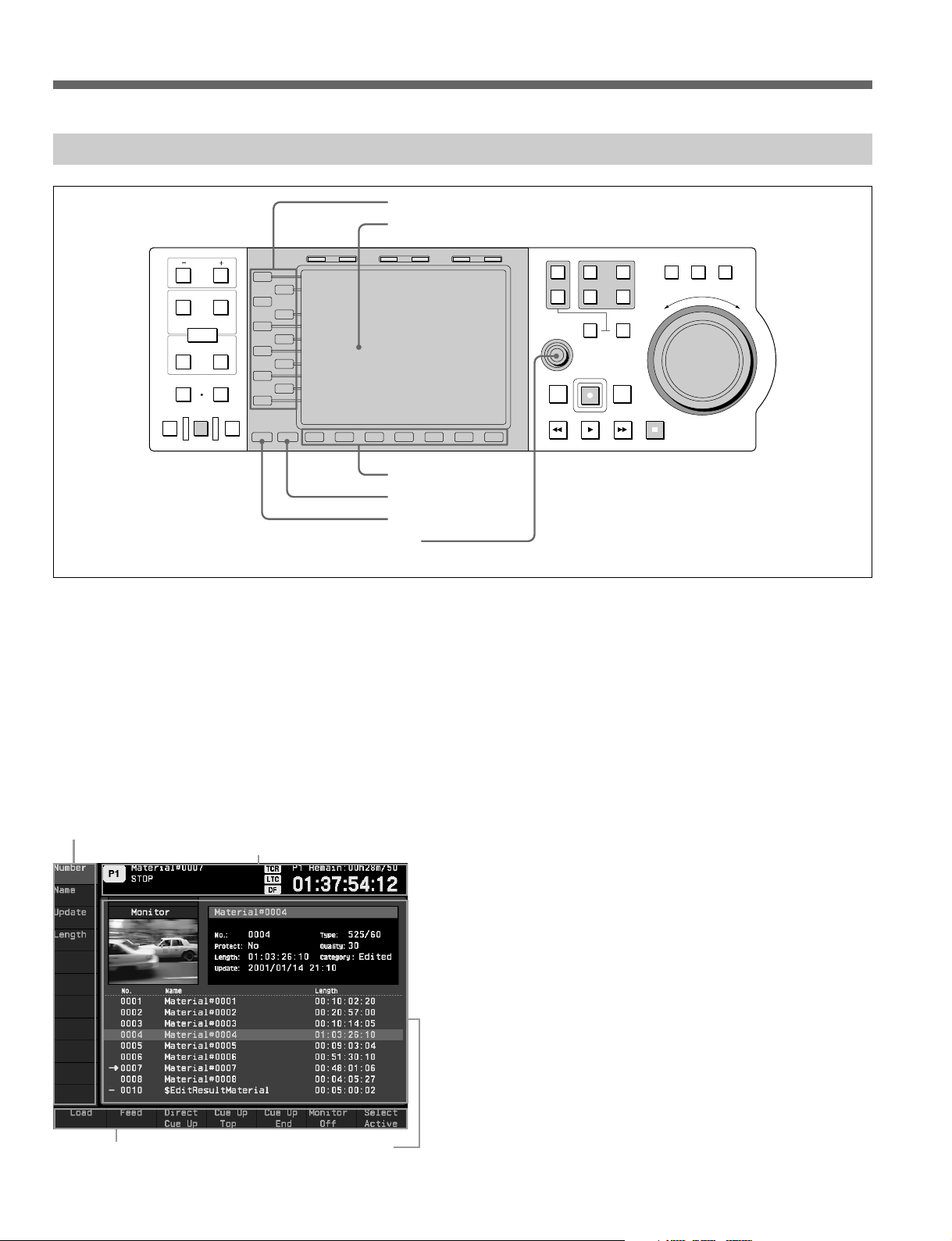
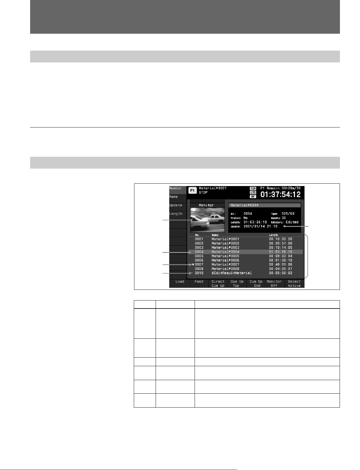
3-2-2 Display Items in Material Mode
The items displayed when material mode is selected are as follows.
Number
1
2
3
4
5
6
1
4
5
6
Name
Monitor screen
Selected
material
information
Material list
Cursor
n mark
–– mark
2
3
Example of display in material mode
Display contents
This displays the monitor screen for the port that is currently the
subject of operation, or a stamp picture of material selected by the
cursor in the material list. You can select the screen to be displayed
through the Material Monitor setting of the Setup mode or using the
B6 key.
This shows all the material attributes, such as the name, number,
length, and the update date of the material on which the cursor is
positioned.
This is a list of materials. One line corresponds to one material.
Use the MULTI CONTROL knob to move the cursor from one line
to another in the material list.
Indicates material assigned to the port that is currently the subject
of operation.
Indicates material assigned to ports other than that which is
currently the subject of operation.
By moving the cursor (4) from one line to another using the MULTI
CONTROL knob, you can select the material to which operations apply. For
material at the cursor position, all attributes are displayed.
If you turn the MULTI CONTROL knob while pressing the SHIFT key, the
cursor jumps ten items at a time.
Chapter 3 Operating Modes 3-3 (E)
Page 30
3-2 Material Mode
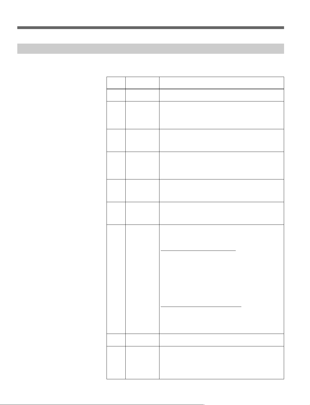
3-2-3 Key Assignments in Material Mode
In material mode, the function keys to the left of and below the liquid crystal
display (B1 to B7, and L1 to L11) are assigned to functions as follows.
Key
L1 - L4
B1
B2
B3
B4
B5
B6
B7
SHIFT
+B1
Function name
(caption)
(Sort keys)
Load
Feed
Direct Cue Up
Cue Up Top
Cue Up End
Monitor Auto/
On/Off
Select Active
Unload
(New Material)
Description
These sort the material list.
Assigns a material to the port currently the subject of
operation. This operation is only possible for a playback or
unused recorder port. When you assign a material to an
unused recorder port, press this key while pressing the
EDIT button.
This sets the transfer speed for A/V data transfer when you
hold down this key and turn the search dial. If you release
this key, the material is loaded at the transfer speed that
you set.
Displays Time Data Entry dialog box so you can set the
cue-up position. Cue up is executed for the current timer
mode. This feature is enabled only for material assigned to
the playback port to be operated or material assigned to the
EXT port.
Move to the beginning of the material assigned to the port
currently the subject of operation. This is only effective for
material assigned to the playback port currently the subject
of operation.
Move to the end of the material assigned to the port
currently the subject of operation. This is only effective for
material assigned to the playback port currently the subject
of operation.
Switches the type of image displayed on the monitor
(monitor image or stamp picture). Operation varies
according to the Material Monitor setting (Auto or Manual)
made in the Setup mode.
When Material Monitor is set to Auto:
Auto appears above the B6 button, indicating that display
automatically switches between the monitor screen and
stamp picture (the B6 button is not effective). When auto
switching is on, the monitor screen displays in the following
instances:
• When the playback port is the subject of operation and the
cursor is positioned on material assigned to that port
• When the recording port is the subject of operation
In all other instances, the stamp picture for the material
selected with the cursor is displayed.
When Material Monitor is set to Manual:
The indication above the B6 button is switched ON and
OFF each time you press the button. When the indication is
ON, a stamp picture is displayed for the material selected
by the cursor; when it is OFF, the monitor screen for the
port that is the subject of operation is displayed.
This moves the cursor to the material in the list that is
assigned to the port currently the subject of operation.
Unloads the material assigned to the port currently the
subject of operation. This is only effective for material
assigned to the port currently the subject of operation.
When BVE mode is the MAV-555 mode of operation and no
material is assigned to the RP port, you can assign new
material to the port by pressing this button.
3-4 (E) Chapter 3 Operating Modes
Page 31

Key
SHIFT
+B3
SHIFT
+B4
SHIFT
+ B5
SHIFT
+ B6
SHIFT
+ B7
Function name
(caption)
Cut Out
Material
Protect On/Off
Rename
Delete
Capture New
Stamp
Description
Cuts out an area from the loaded material that is currently
selected, and creates new material. VIDEO only or AUDIO
only cutouts are not possible.
Selects whether material can be deleted and whether
attributes can be changed.
Change name of the material.
Deletes material. All material not protected with the Protect
feature can be deleted with one execution (Batch Delete).
Use of Delete or Batch Delete is effective only for material
that is not assigned to any port.
Switches the stamp picture for material that is assigned to
the port that is currently the subject of operation.
* Material stamp screens can be numbered 0001 through
0999. When recording from the control panel, the material
destination screen is automatically recorded as the stamp
screen.
For details about how to enter time data, see section “3-7-1 Time Data Entry Dialog
Box” (page 3-42).
For Material Monitor settings, see section “3-6 CP Setup Mode” (page 3-34).
For details on BVE mode, see “5-4 Basic Operations in BVE Mode” in
the MAV-555 Operation Manual.
When EXT1 or EXT2 is designated as the port to be currently operated, the B1
key and SHIFT+B1 keys can be used as described below.
Key
B1
SHIFT+
B1
Function name
(caption)
Standby On/
Off
Eject
Description
Switches Standby On/Off for the external VTR assigned to
the current port to be operated.
Ejects the cassette mounted in the external VTR assigned
to the current port to be operated.
Chapter 3 Operating Modes 3-5 (E)
Page 32

3-2 Material Mode
3-2-4 Sorting the Material List
In material mode you can sort the material shown in the material list, using
material attributes as keys. A material has the following attributes:
Material name (NAME): A name for the material consisting of a
Material number (NUMBER): A number attached to the material
Material Length (LENGTH): The length of the material
Update date (UPDATE): The date and time of creation or last update
In addition, material has the following attributes:
Material protect (PROTECT): Shows whether material can be deleted and
Signal type (TYPE): Shows whether material was stored at 525/
Picture quality (QUALITY): Shows the picture quality of the material.
Material type (CATEGORY): Shows whether material is recorded (RAW)
maximum of 23 ASCII characters
of the material
whether attributes can be changed.
60, 625/50, 525/60SS, 625/50SS.
or edited (EDITED).
To sort the material list by specific attributes
To sort the material list, use the following procedure.
1 Enter material mode.
2 Press one of the function keys L1 to L4 according to the attribute by which
you want to sort. This sorts the material list in ascending order by the
attribute corresponding to the key.
Note
After sorting the cursor position does not move from the material selected
before the sort.
3-2-5 Selecting the Active Material (SELECT ACTIVE)
The material assigned to the port which is currently the subject of operation is
termed the “active material.” By pressing the SELECT ACTIVE key you can
rapidly select the active material.
To select the active material
3-6 (E) Chapter 3 Operating Modes
1 Press function key B7 (Select Active).
The cursor jumps to the line for the material assigned to the port currently
the subject of operation, and the active material is now selected.
Page 33

3-2-6 Loading and Unloading Material (LOAD/UNLOAD)
To assign a material to the port currently the subject of operation, press the
LOAD key. The LOAD operation corresponds to inserting a cassette in a
VTR.
To cancel the assignment of material to the port currently the subject of
operation, press the UNLOAD key. The UNLOAD operation corresponds to
ejecting a cassette from a VTR.
To load a material into the port currently the subject of operation
To load a material, use the following procedure.
1 With the MULTI CONTROL knob, move the cursor to the material that
you want to assign.
2 Press function key B1 (Load).
• The LOAD operation begins, and the material selected in step 1 is
assigned to the port currently the subject of operation.
• At the same time as assigning the material to the port, the system cues up
to the beginning of the material.
• After assigning the material, you can use the transport buttons and search
dial to carry out various playback operations.
For details of playback operations, see Chapter 5, “Playback.”
Notes
• LOAD can only be executed for a playback or unused recorder port.
• Depending on the 0006: Load Without Unloading setting made in the Setup
mode, you may need to manually unload material before loading. See section
“3-6 CP Setup Mode” (page 3-34).
To unload the material from the port currently the subject of operation
To unload material press the B1 (unload) button while holding down the shift
key. The material is unloaded, and the port that is currently the subject of
operations is released.
Note
If there is no material assigned to the port that is currently the subject of
operation, the “Unload” caption on the SHIFT+B1 key is dimmed, indicating
that the key is not valid.
Chapter 3 Operating Modes 3-7 (E)
Page 34

3-2 Material Mode
To load a material in a currently unused recorder port
When the recorder port currently the subject of operation is unused, you can
load material to it by using the EDIT button and function key B1 (Load).
1 With the MULTI CONTROL knob, move the cursor to the material that
you want to assign.
2 Press function key B1 (Load) while pressing the EDIT button.
• The LOAD operation begins, and the material selected in step 1 is
assigned to the port currently the subject of operation. At the same time,
the system cues up the end of the material.
• If the power goes off during loop recording, you can reassign material
and resume recording.
For details about function keys, see section “3-2-3 Key Assignments in
Material Mode” (page 3-4).
Notes
• It only possible to load loop recorded material in this way. It is not possible
to load material recorded normally.
• It is not possible to load a material this way when using the MAV-555SS in
SS mode.
• It is not possible to load the following types of material. If you attempt to
load one of these types of material, when you press the EDIT button the
“Load” caption on the B1 (Load) key is dimmed, indicating that the key is
not valid.
- SS material (recorded in SS mode)
- Material loaded to a different port
- Material for which the Protect attribute is “Protected”
- Material for which the Category attribute is “Edited”
• The settings of loaded material comply with CP Setup mode items 0001:
Record Allocate Length and 0002 Record Loading Option. Because of these
settings, if a material is long, loading is possible, but it is not possible to
record from the end of the material.
If you want to record from the end of the material, modify the allocated
record length in CP Setup mode item 0001: Record Allocate Length.
• If you stop loop recording when System Remain has reached zero (0), it is
not possible to reload the same material to an unused recorder port because
System Remain is zero.
To switch the material in the material list
Material assigned to the port that is currently the subject of operation can be
switched in the material list using the F.FWD and REW buttons. To switch the
material, 0007: Material Index Jump in the Setup mode must be set to an item
other than Disable.
For settings, see section “3-6 CP Setup Mode” (page 3-34).
3-8 (E) Chapter 3 Operating Modes
Page 35

3-2-7 Deleting and Renaming Material (DELETE/RENAME)
In material mode you can delete a material or change the material
name. It is also possible to delete or change the name of material that is
not assigned to any port.
To delete material
To delete material, use the following procedure.
1 In the material list, move the cursor to the material you want to delete.
2 Hold down the SHIFT key, and press B6 (Delete).
A dialog box appears to ask you to confirm the deletion. To cancel the
deletion, press B6 (Cancel) here.
3 To confirm the deletion, hold down the SHIFT key, and press B7 (OK).
Note
If the selected material is opened on any port, it cannot be deleted. In this case,
first unload the material, then repeat the delete operation.
For details of unloading material, see section “3-2-6 Loading and Unloading Material
(LOAD/UNLOAD)” (page 3-7).
To delete materials in one batch
Materials held on the MAV-555 that are not protected with the Protect feature
can be deleted in one batch. To delete materials in one batch, use the following
procedure.
1 Display the select material information for all the materials that you want
to delete, and then confirm that the Protect attribute is set to No. If a
material that you want to delete is set for Protected, hold down SHIFT, and
press B4 (Protect On/Off) to cancel Protect.
For material that you do not want to delete, set the Protect attribute to
Protected.
2 In the material list, select the one material that you want to delete.
3 Hold down the SHIFT key, and press B6 (Delete). A dialog box appears to
ask you to confirm the deletion. To cancel the deletion, press B6 (Cancel).
4 Hold down the SHIFT key, and press B4 (Batch Delete).
5 A dialog box appears to ask you to confirm the deletion. To cancel the
deletion, press B6 (Cancel).
Chapter 3 Operating Modes 3-9 (E)
Page 36

3-2 Material Mode
To rename material
6 To confirm the deletion, hold down the SHIFT key and press B7 (OK).
Notes
• If any selected material is currently open on a port, you can execute Batch
Delete but the open file cannot be deleted. In this case, unload the opened
material, and then repeat the Batch Delete (or Delete) operation.
• During Batch Delete execution, no other operation can be conducted from the
control panel.
For details about unloading material, see section “3-2-6 Loading and Unloading
Material (LOAD/UNLOAD)” (page 3-7).
To rename material, use the following procedure.
1 In the material list, move the cursor to the material you want to rename.
2 Hold down the SHIFT key, and press B5 (Rename).
A text input dialog box appears to allow you to enter a name.
3-2-8 STEP Operation
3 Enter the new name for the material.
For details of the method of entering text in the dialog box, see section “3-7-2
Text Entry Dialog Box,” (page 3-44).
4 To carry out the renaming, press B7 (OK).
To cancel the renaming, instead of B7, press B6 (Cancel).
Notes
• It is not possible to rename material to a name which conflicts with the name
of an existing material.
• Material names can be up to twenty-three letters long.
• The slash “/”, percent “%”, underscore “_”, and dollar sign “$” are reserved
by the system. When modifying material names, never use “/” and do not use
“%”, “_”, or “$” as the first character.
The STEP operation can now be used with the loaded material.
You can easily search for edit points in specific STEP increments that, until
now, were difficult to jump to in increments for Frames and Fields using the
search dial.
To use STEP
3-10 (E) Chapter 3 Operating Modes
1 In the CP Setup mode set “0015 Step Unit” to the desired value.
2 Hold down the Shift key and press the TRIM button (+ or –).
The STEP command is executed using the value you selected for the Step
Unit in the CP Setup mode.
Page 37

3-3 Edit Mode
This section introduces the edit mode and explains edit mode display and basic
operation.
For the basic edit operation sequence, see Chapter 6, “Editing.”
3-3-1 Overview of Edit Mode
Edit mode allows you to edit data and manage it. Edit data can be managed as
pages with IN and OUT points set for source material and destination material,
or as a stack of pages called a program.
In edit mode, PLAYER and RECORDER edit points are displayed on the LCD
display.
Pages and programs are basic concepts related to editing through the control panel.
For details on these items, see section “1-3 Overview of Edit Data Management”
(page 1-3).
In the edit mode, in order to conduct batch editing for Assemble/All, Video,
Audio for the Video/Audio mode, an Audio Channel mode is available for
separate editing of four audio channels. While editing in the Audio Channel
mode, you can use material edited with the Effect Transition feature of the
optional board BKMA-560.
Video/Audio Mode
Edit Mode
Audio Channel Mode
Selecting Edit Mode
To switch between these editing modes, use the 2003: Channel Selection
Mode feature in the CP Setup mode.
For details about the CP Setup mode, see section “3-6 CP Setup Mode” (page 3-34).
Note
With Audio Channel mode selected, material cannot be handled in units of
pages.
For details about pages, see section “6-1 Overview of Editing Operations” (page 6-1).
To select the edit mode, hold down the MODE button, then press function key
L2.
Chapter 3 Operating Modes 3-11 (E)
Page 38

3-3 Edit Mode
3-3-2 Overview of the Video/Audio Mode
This section describes the display items and key assignments when the Video/
Audio mode is selected in the Edit mode.
Items Displayed in the Video/Audio Mode
The items displayed in the Video/Audio mode are as follows.
qd
5 1 2
3
Number
1
2
3
4
5
6
7
8
9
qg
qf
6
9
Name
Editing mode
Source
material name
OUT point
stamp picture
IN point stamp
picture
Monitor display
area
Recorder IN
point
Recorder OUT
point
Recorder
duration
Player IN point
4
qs 70
Example of Video/Audio mode display
Information displayed
Indicates whether editing is in the page insert mode or the
page overlay mode.
Name of the material opened on the PLAYER port that is to
be used as the edit source.
The stamp picture for the PLAYER OUT point.
The stamp picture for the PLAYER IN point.
Shows the monitor screen of the device that is being
controlled.
The time data (TM2) for the recorder IN point. Displays both
V (video) and A (audio) IN points during/when split editing.
The time data (TM2) for the recorder OUT point. Displays
both V (video) and A (audio) OUT points during/when split
editing.
The duration between recorder edit intervals. Displays both
V (video) and A (audio) duration during/when split editing.
The time data for the player IN point. During split editing,
both V (video) and A (audio) IN points are displayed.
qa 8
3-12 (E) Chapter 3 Operating Modes
Page 39

Number
0
qa
qs
qd
qf
qg
Name
Player OUT
point
Player duration
Cursor
Channel
Total time
Page
Information displayed
The time data for the player OUT point. During split editing,
both V (video) and A (audio) OUT points are displayed .
The duration between player edit intervals. During split
editing, both V (video) and A (audio) duration are displayed.
Move between IN, OUT, and DUR using the MULTI
CONTROL knob. Moves between V/A if used with SHIFT
during split editing.
Indicates the appropriate channel combination for edit point
data.
Displays the total duration up to the current page or the total
duration for program operation, according to how the Total
Time Type is set in the CP Setup mode.
The current position of the page currently being processed
in the program on the control panel.
For details about the Total Time Type setting, see “Summary of control panel setup
items” (page 3-34).
Notes
• Edit points set automatically are marked with a “ . ” on the end.
• If selected edit points do not exist in the material, the edit point flashes on the
display.
• If the side of the stamp screen is marked with an “*”, that stamp screen is the
2nd field. Since operations such as cue-up are performed with respect to the
1st field, you can cue up to images other than stamped pictures.
Chapter 3 Operating Modes 3-13 (E)
Page 40

3-3 Edit Mode
Key Assignments in the Video/Audio Mode
The following is a list of the function keys (L1 to L7 and B1 to B7) on the left
and bottom sides of the LCD in the Video/Audio mode.
Key
L1
L2
L3
B1
B2
B3
B4
B5
B7
SHIFT+B1
SHIFT+B2
SHIFT+B3
SHIFT+B4
SHIFT+B5
SHIFT+B6
SHIFT+B7
IN (or
OUT) +
B4
Function name
(caption)
Assemble/All
Video
Audio
Current TC
Entry
Manual TC
Entry
Editing Mode
LastEdit
UndoEdit
Search
(Cancel Move/
Paste/Delete/
Modify)
BS
FS
1st Edit
Copy Page
Paste Page
Delete Page
Move Page
LAST X
Description
Selects all channels as edit channels.
Specifies Video as the editing channel.
Specifies Audio (all channels) as the editing channel.
Inputs the current time code as the edit point.
Allows you to enter a recognized time code as an edit
point. After IN and OUT points have been input, you can
enter DUR (duration).
Switches insert mode between insert and overlay when
editing pages.
Restores all edit points (PLAYER IN/OUT/DUR and
RECORDER IN/OUT/DUR) to their status immediately
before the most recent edit, or immediately before the
most recent preview.
Cancels the content of the most recent edit. However,
only the most recent edit can be deleted.
Runs a search for edit points.
If you press this button immediately after performing Move
Page, Copy Page, Paste Page, and Delete Page
operations, or modifying pages, you can cancel edit
operations for the page you have just edited.
Moves to the previous page of the currently displayed
page. Data is modified after moving to the previous page,
and this button is ineffective until the modifications are
confirmed using AUTO EDIT.
Moves to the next page of the currently displayed page.
This button is disabled until AUTO EDIT confirms data
correction of a page after it has been moved.
Clears the current program so a new program can be
created.
Copies page data.
Pastes copied page data onto a new page.
Deletes pages.
Moves pages.
Restores the last changed edit point to its previous status.
3-14 (E) Chapter 3 Operating Modes
Page 41

3-3-3 Overview of the Audio Channel Mode
This section describes the display items and key assignments when Audio
Channel mode is selected for the edit mode. Material cannot be handled in
units of pages in the Audio Channel mode.
Items Displayed in the Audio Channel Mode
The items displayed in the Audio Channel mode are as follows.
5 1 2
Number
1
2
3
4
5
6
7
8
9
0
qd
qf
6
9
Name
Editing mode
Source
material name
OUT point
stamp picture
IN point stamp
picture
Monitor display
Recorder IN
point
Recorder OUT
point
Recorder
duration
Player IN point
Player OUT
point
3
4
qg
qh
qj
qk
ql
w;
wa
ws
wd
0
qs
7
qa 8
Information displayed
Indicates whether editing is in the page insert or page
overlay mode.
Name of the material opened on the PLAYER port that is to
be used as the edit source.
The stamp picture for the PLAYER OUT point.
The stamp picture for the PLAYER IN point.
Shows the monitor screen of the device that is being
controlled.
The time data (TM2) for the Recorder IN point. Displays
both V (video) and A (audio) IN points during split editing.
The time data (TM2) for the Recorder OUT point. Displays
both V (video) and A (audio) OUT points during split editing.
The duration between recorder edit intervals. Displays both
V (video) and A (audio) duration during split editing.
The time data for the Player IN point. Displays both V
(video) and A (audio) IN points during split editing.
The time data for the Player OUT point. Displays both V
(video) and A (audio) OUT points during split editing.
Chapter 3 Operating Modes 3-15 (E)
Page 42

3-3 Edit Mode
Number
qa
qs
qd
qf
qg
qh
qj
qk
ql
w;
wa
ws
wd
Name
Player duration
Cursor
Channel
Total time
Effect pattern
Effect pattern
no.
Video
transition time
Audio
transition time
Border width
Border
luminance
Border
saturation
Border hue
Soft width
Information displayed
The duration between Player edit intervals. Displays both V
(video) and A (audio) duration during split editing.
Moves between IN, OUT, and DUR using the MULTI
CONTROL knob. Moves between V/A if used with SHIFT
during split editing.
Indicates the appropriate channel combination for edit point
data.
The length of the destination material, or the duration from
the beginning of the destination material to the OUT point,
determined by the Total Time Type selection in the CP
Setup mode.
The pattern of the video effect to be edited.
The number of the video effect to be edited.
The transition time in units of frames for the video effect.
Nothing is displayed if an effect pattern disabled for video
transition time is selected.
The audio transition time.
The width of the video effect. Nothing is displayed if an
effect pattern disabled for border is selected.
The border luminance (Lum) of the video effect. Nothing is
displayed if an effect pattern disabled for border is selected.
The border saturation (Sat) of the video effect. Nothing is
displayed if an effect pattern disabled for border is selected.
The border hue (Hue) of the video effect. Nothing is
displayed if an effect pattern disabled for border is selected.
The soft width of the video effect (Width). Nothing is
displayed if an effect pattern disabled for soft is selected.
For details about the Total Time Type setting, see “Summary of control panel setup
items” (page 3-34).
Notes
• Edit points set automatically are marked with a “ . ” at the end.
• If selected edit points do not exist in the material, the edit points flashes on
the display.
• If the side of the stamp screen is marked with an “ * ”, that stamp screen is
the 2nd field. Since operations such as cue-up are performed with respect to
the first field, you can cue up to images other than stamped pictures.
3-16 (E) Chapter 3 Operating Modes
Page 43

Key Assignments in Audio Channel Mode
The following is a list of the function keys (L1 to L7 and B1 to B7) on the left
and bottom sides of the LCD in the Audio Channel mode.
Key
L1
L2
L3 to L6
B1
B2
B3
B4
B5
B6
B7
SHIFT +
L1 to L11
SHIFT +
B3
IN (or
OUT) +
B4
Function name
(caption)
Assemble/All
Video
Ch1 to Ch4
Current TC
Entry
Manual TC
Entry
Editing Mode
Last Edit
Undo Edit
Effect
Search
Effect Shortcut
1st Edit
LAST x
Description
Selects all channels as edit channels.
Specifies Video as the editing channel.
Specifies each Audio channel (Ch1 to Ch4) as the editing
channel.
Inputs the current time code as the edit point.
Allows you to enter a desired time code as an edit point.
After entering the IN and OUT points, you can enter DUR
(duration).
Switches insert mode between insert and overlay when
editing pages.
Restores all editing points (Player IN/OUT/DUR and
Recorder IN/OUT/DUR) to the status immediately before
the previous edit or preview.
Cancels the content of the most recent edit. However,
only the most recent edit can be deleted.
Displays the Effect dialog box so you can specify the
effect to be used for editing.
For details, see “3-7-5 Effect Dialog Box” (page 3-48).
Runs a search for edit points.
Retrieves one of the effects registered under keys L1 to
L11 as shortcuts, and specifies the selected effect to be
used for the current edit.
For details about registering and deleting shortcuts, see “Using
Shortcuts” (page 3-51).
Clears the current program so you can create a new
program.
Restores the last changed edit point to its previous status.
Chapter 3 Operating Modes 3-17 (E)
Page 44

3-3 Edit Mode
3-3-4 Clearing Programs
To clear programs
Only one program at a time can be managed from the control panel. Therefore,
all open programs must be cleared before beginning new editing jobs.
Programs can be cleared as follows:
1 Hold down the MODE key and press L2 (EDIT), or press the PLAYER
button or the RECORDER button to enter the edit mode.
2 Hold down the SHIFT key and press B3 (1st Edit).
A dialog box opens and asks you to confirm that you want to clear the
program.
3 To confirm clearing the program, hold down the SHIFT key and press B7
(OK).
A Text Entry dialog box opens and displays the default
EditResultMaterial#xxxx
where “xxxx” is an automatically incremented consecutive number.
Treating material during editing
3-18 (E) Chapter 3 Operating Modes
4 You can now change the material name as you desire. Use the Text Entry
dialog box to enter a new material name. The material name has a
maximum length of 23 alphanumeric characters.
For details about how to enter text in a Text Entry dialog box, see section “3-7-2
Text Entry Dialog Box”, (page 3-44).
5 Press B7 (OK) to clear the program.
The new material name takes effect and the Text Entry dialog box closes.
Notes
• In order to cancel the program clear procedure, press B6 (Cancel) at Step 3 or
Step 5 to close the dialog box.
• If a material file already exists with the material name you choose in Step 4, a
dialog box will open to tell you that the material name you have chosen is
already in use. In this case you will not be able to clear the program.
• The slash “/”, percent “%”, underscore “_”, and dollar sign “$” are reserved
by the system. When modifying material names, never use “/” and do not use
“%”, “_”, or “$” as the first character.
Destination material (material currently being managed as a program) can be
assigned to the playback port from material mode and played back the same as
ordinary material. However, if you assign destination material to a playback
port, you cannot add new edit points or modify existing edit points in edit
mode. In order to do this, you must voluntarily unload all assigned destination
material.
For how to unload material, see section “3-2-6 Loading and Unloading Material”
(page 3-7).
Page 45

3-3-5 Inputting Editing Points
To input edit points
Until now, there were two methods of inputting edit points: using the same IN
button, or OUT button and ENTRY button that is used for VTR, and inputting
edit point values from the control panel’s GUI.
For a more detailed explanation of editing operations, see Chapter 6, “Editing.”
Input edit points as follows:
1 Move the cursor to the edit point you want to input (either the IN point or
the OUT point) using the MULTI CONTROL knob.
2 Input the time data.
Input time data using the CURRENT TC ENTRY command or the
MANUAL TC ENTRY command.
2-1 If you press the B1 key (CURRENT TC ENTRY), the current time
data is input.
2-2 If you press the B2 key (MANUAL TC ENTRY), the Time Data
Entry dialog box appears, and you can input optional time data.
For the Time Data Entry dialog box, see section “3-7-1 Time Data Entry
Dialog Box” (page 3-42).
Note
If either the IN or OUT point is input, you can input edit interval length by
moving the cursor to duration (DUR) and running the MANUAL TC ENTRY
command.
Chapter 3 Operating Modes 3-19 (E)
Page 46

3-3 Edit Mode
3-3-6 Searching for Edit Points
To search for edit points using the on-screen command buttons, move the
cursor to the edit point you want to search for (either an IN point or an OUT
point) using the MULTI CONTROL knob, and press the B7 key (SEARCH).
You can also search by simultaneously pressing the IN or OUT button together
with PREROLL, the same as with the VTR.
3-3-7 Restoring Previous Editing Points
Recalling the Last Editing Point Edited or Previewed (LAST EDIT)
The value of the last point edited or previewed can be recalled.
To restore last point edited
1 After editing the point with AUTO EDIT, press Last Edit (B4).
The last point edited (Player IN/OUT/DUR point, or Recorder IN/OUT/
DUR point) is displayed. Only the last point registered can be displayed.
2 Correct the edit point as required.
To restore last point previewed
1 To return the previous status of the last edit point that was changed, press
Last Edit (B4).
The data for the edit point when Preview was last executed is displayed.
For details about changing the edit point, see “To modify selected edit points” (page
6-16).
3-20 (E) Chapter 3 Operating Modes
Page 47

Restoring a Changed Edit Point to the Original Value (LAST X)
If you make a mistake while entering new data for an edit point, you can
restore the original entry quickly with the LAST X key.
1 Press the RECORDER or PLAYER key select the device for which you
want to display the edit point.
2 Hold down either the IN or OUT button for the edit point that you want to
restore, and press the B4 key (Last X).
The last edit point changed is displayed.
3 Press these keys again to delete the value before the change and display the
data after it was changed. Hold down the IN or OUT button, and press the
B4 key (Last X) to alternate the display between the original value and the
new value.
Note
When the MAV-555 is switched off, all previous edit points held on the MAV555 are lost. For this reason, once the MAV-555 is switched off the edit points
specified before it was switched off cannot be recovered.
Chapter 3 Operating Modes 3-21 (E)
Page 48

3-3 Edit Mode
3-3-8 Edit Cancel
Canceling the Previous Edit
The content of editing can be canceled immediately after it has been edited.
Only the content of the previous edit can be canceled.
Use the following procedure to cancel the previous edit.
1 Press the AUTO EDIT key to execute editing.
2 Press B5 (Undo Edit). A dialog box appears and asks you to confirm that
you want to cancel the previous edit. If you want to cancel the operation,
press B6 (Cancel). The edited data is canceled and the previous data before
editing is restored.
3 To cancel the contents the previous edit, hold down the SHIFT key and
press B7 (OK).
The immediately previous edit is canceled and the display jumps to the site
of the canceled edit. If an editing point does not exist, the display jumps to
the last position in the file.
Note
When the MAV-555 is switched off, the contents of the previous edit held on
the MAV-555 are lost. For this reason, once the MAV-555 is switched off the
contents of a previous edit cannot be deleted.
3-22 (E) Chapter 3 Operating Modes
Page 49

3-4 Time Difference Function
3-4-1 Overview of Timer Rec/Play Mode
Timer Rec/Play mode allows you to record material in units of cue sheets, and
then preview them or select them for play.
A cue sheet is the material obtained from a single recording, preview, or play,
referred to as timer events. A single cue sheet can be created from up to 3
timer events.
Recording
Sets items such as the type, port, start date,
and time for preset recording.
Cue sheet
All cue sheet settings can be made in the Cue Sheet dialog box. For details, see section
“3-7-6 Cue Sheet Dialog Box” (page 3-54).
Notes
• An external device cannot be used to handle timer event data.
• Up to 10 cue sheets can be preset.
• The first 4 seconds of recorded material cannot be previewed.
• If the port is on standby or being executed, any operations on the port are
prohibited except for pressing the PLAY and REC buttons. However, if the
play start position (Position) is set to “Manual”, it is also possible to use the
search operation section.
Selecting Timer Rec/Play Mode
To select Timer Rec/Play mode, hold down the MODE button and press the
L3 function key.
3-4-2 Items Displayed in Timer Rec/Play Mode
Preview
Play
Sets whether material is previewed.
Sets items such as the type, port, start date,
and time for preset play.
The items displayed when Timer Rec/Play mode is selected are as follows.
2
1
7
5
6
Example of display in Timer Rec/Play mode
Chapter 3 Operating Modes 3-23 (E)
3
4
Page 50

3-4 Time Difference Function
Number
1
2
3
4
5
6
7
Name
Monitor screen
Date & time
Selected event
information
Event list
Cursor
Sub cursor
Status
Information displayed
This displays the monitor screen that is currently selected.
This displays the current date and time.
This displays timer event information for the timer event
selected by the cursor in the event list.
This is an event list. One line corresponds to one event.
Use the MULTI CONTROL knob to move the cursor from
one line to another in the event list.
This indicates the event specified on the cue sheet that
corresponds to the event on which the cursor is positioned.
This displays the operation status of the current event.
…….: In Standby mode.
STANDBY: Material has been opened.
EXECUTE: Recording, playing, or previewing.
DONE: Finished recording, playing, or previewing.
ERROR: An error has occurred.
WARNING: A warning has occurred.
3-4-3 Key Assignments in Timer Rec/Play Mode
In Timer Rec/Play mode, the function keys to the left and below the liquid
crystal display (L1 to L3, and B1 to B6) are assigned to the following
functions.
Key
L1 – L3
B2
B3
B4
B5
SHIFT
+B6
Function name
(caption)
(Sort keys)
New Cue
Sheet
Modify Cue
Sheet
Scroll Left
Scroll Right
Delete Cue
Sheet
Description
These sort the event list.
Displays the Cue Sheet dialog box so you can create a
new cue sheet.
Retrieves the cue sheet for the event on which the cursor
is positioned in the event list so you can modify it.
Scrolls left through the event list.
Scrolls right through the event list.
Deletes the cue sheet for the event on which the cursor is
positioned in the event list.
3-24 (E) Chapter 3 Operating Modes
Page 51

3-4-4 Sorting the Event List
In Timer Rec/Play mode, you can sort the events selected with the cursor in
the event list, using event attributes as keys. The following three attributes can
be used for sorting:
Event start time (START): The start time of the selected event.
Event end time (END): The end time of the selected event.
Port (PORT): The port used for the selected event.
In addition, events selected with the cursor have the following attributes:
Date: The date the selected event is executed.
Type (TYPE): Event type (REC, PLAY, PVW)
To sort the event list by specific attributes
To sort the event list, use the following procedure.
1 Enter Timer Rec/Play mode.
Type (1 Time, Loop, Daily, Weekly)
Port (R1, R2, R3, P1, P2, P3)
Trigger (Auto, Manual, Delay)
2 Press one of the function keys L1 to L3 according to the attribute by which
3-4-5 Creating New Cue Sheets
You can create a new cue sheet when you want to make recording, preview, or
play settings.
To create a new cue sheet
1 Press function key B2 (New Cue Sheet).
you want to sort the list. This sorts the event list in ascending order by the
attribute corresponding to the key.
The new Cue Sheet dialog box opens and you can make detailed event
settings.
For details on the Cue Sheet dialog box, see section “3-7-6 Cue Sheet Dialog
Box” (page 3-54).
Chapter 3 Operating Modes 3-25 (E)
Page 52

3-4 Time Difference Function
3-4-6 Modifying the Contents of Cue Sheets
You can retrieve cue sheets for existing events modify the recording, preview,
and play settings.
To modify the contents of cue sheets
1 Move the cursor to the event for which you want to modify the contents.
2 Press function key B3 (Modify Cue Sheet).
The existing Cue Sheet dialog box opensand you can modify event
settings.
For details on the Cue Sheet dialog box, see section “3-7-6 Cue Sheet Dialog
Box” (page 3-54).
Notes
• You cannot modify events that display the status DONE or ERROR.
• You can only modify the End time for events that display the status
STANDBY or EXECUTE.
• When the displayed status of a recording event is STANDBY or EXECUTE
and the end time of that event is changed so that the recording time exceeds
the available capacity, the original end time is used for recording instead of
the new one.
3-4-7 Deleting Cue Sheets
To delete cue sheets of existing events, use the following procedure.
1 In the event list, move the cursor to the event that you want to delete.
2 Hold down the SHIFT key and press B6 (Delete Cue Sheet).
A dialog box appears to ask you to confirm the deletion. To cancel, press
B6 (Cancel) here.
3 To confirm the deletion, hold down the SHIFT key and press B7 (OK).
All the settings of the selected cue sheet are deleted.
3-26 (E) Chapter 3 Operating Modes
Page 53

3-5 Dual Play Mode
3-5-1 Overview of Dual Play Mode
In Dual Play mode, you can set items such as the IN and OUT points, and
playback port information for KEY signal material and material to which you
want to add effects. This mode allows you to load or unload material in a
single operation and perform the synchronized playback of two set materials .
Moreover, you can specify an image as the foreground effect (the image is
entered when the effect is enabled) and another as the background effect. An
“alias” is a data structure that contains information about these two different
types of material, and is configured as follows.
Name
Sets the alias name.
Alias
Selecting Dual Play Mode
Loop
Foreground
Background
IN point, OUT point, duration
Port
IN point, OUT point, duration
Port
Specifies whether loop playback is enabled or
not.
Makes IN and OUT point, duration, and port
settings for the material specified as the
foreground.
Makes IN and OUT point, duration, and port
settings for the material specified as the
background.
All alias settings can be made in the Alias Sheet dialog box. For details, see section
“3-7-8 Alias Sheet Dialog Box” (page 3-61).
Note
You can create up to 400 alias settings.
To select Dual Play mode, hold down the MODE button, and then press
function key L4.
Chapter 3 Operating Modes 3-27 (E)
Page 54

3-5 Dual Play Mode
3-5-2 Items Displayed in Dual Play Mode
The items displayed in Dual Play mode are as follows.
1
2
Number
1
2
3
4
5
4
5
Name
Monitor display
Selected alias
information
Alias list
Cursor
t mark
3
Example of Dual Play mode display
Information displayed
Displays the monitor image of the port that is the subject of
operation. When the alias is being loaded or set, the image
at the port that is the subject of operation is automatically
displayed.
Shows all the attributes, such as the name, number,
material name, update date, material length, and loop
settings of the alias on which the cursor is positioned in the
alias list.
CP Setup mode 4006: When Alias Stamp mode is set to FG
Only, the foreground IN point stamp screen is displayed,
and when it is set to Both, both the foreground and
background IN point stamp pictures (see the display
example below) are displayed.
This is an alias list. One line corresponds to one alias.
Use the MULTI CONTROL knob to move the cursor from
one line to another in the alias list.
Indicates aliases that are currently loaded in Dual Play
mode.
3-28 (E) Chapter 3 Operating Modes
Page 55

3-5-3 Key Assignments in Dual Play Mode
In Dual Play mode, the function keys to the left and below the liquid crystal
display (L1 to L11, and B1 to B7) are assigned to the following functions.
Key
L1 – L4
B1
B2
B3
B4
B5
B6
B7
SHIFT
+B1
SHIFT
+B3
SHIFT
+B5
SHIFT
+B6
SHIFT
+B7
Function name
(caption)
(Sort keys)
Load Alias
New Alias
Modify Alias
Cue Up Top
Cue Up End
Direct Cue Up
Select Active
Unload Alias
Match Frame
Rename Alias
Delete Alias
Capture New
Stamp
Description
Sort the alias list.
Loads the alias on which the cursor is positioned.
Opens the alias creation dialog box to allow you to create
a new alias.
Opens the Alias Sheet dialog box of the alias on which the
cursor is positioned in the alias list to allow you to modify
its contents.
Moves to the top of the alias material that is currently
loaded.
Moves to the end of the alias material that is currently
loaded.
Displays the time data input dialog box to specify the cue
up position. Cue up is performed in the current Timer
mode.
Moves the cursor to the alias currently the subject of
operation in the alias list.
Unloads the alias currently the subject of operation.
Corrects unmatched aliases. The alias not currently the
port is matched to the current port.
Allows you to change the name of the alias on which the
cursor is positioned in the alias list.
Deletes the alias on which the cursor is positioned in the
alias list.
Updates the stamp picture of the currently loaded alias.
When you press this combination of buttons, the screen
that appears on the monitor is recorded as the new stamp
picture. Perform this operation after moving the cursor
onto the currently loaded alias. The screen cannot be
recorded when “None” is specified in CP Setup mode
4006: Alias Stamp Mode.
Chapter 3 Operating Modes 3-29 (E)
Page 56

3-5 Dual Play Mode
3-5-4 Sorting the Alias List
In Dual Play mode, you can sort events selected with the cursor in the alias
list, using alias attributes as keys. The following four attributes can be used for
sorting:
Alias number (NUMBER): Number attached to the alias.
Alias name (NAME): Name of the alias consisting of a maximum of 23 ASCII
characters.
Update date (DATE): Date and time of creation or last update of the alias.
Alias length (LENGTH): Length of the material set to the alias.
Note
CP Setup mode 4001: Displays the three attributes selected in Display
Attributes.
To sort the alias list by specific attributes
To sort the alias list, use the following procedure.
1 Enter Dual Play mode.
2 Press one of the function keys L1 to L4 according to the attribute by which
you want to sort. This has the effect of sorting the alias list in ascending
order according to the attribute of the pressed key.
Note
Prior to sorting, the cursor does not move from the selected material.
3-5-5 Selecting the Active Alias (SELECT ACTIVE)
The alias currently the subject of operation in Dual Play mode is referred to as
the “active alias”. By pressing the SELECT ACTIVE key you can rapidly
select the active alias.
To select the active alias
1 Press function key B7 (SELECT ACTIVE).
The cursor jumps to the line of the alias currently loaded and the active
alias is now selected.
3-30 (E) Chapter 3 Operating Modes
Page 57

3-5-6 Loading and Unloading an Alias (LOAD ALIAS/UNLOAD ALIAS)
To load an alias in Dual Play mode, press the Load Alias key.
To cancel loading an alias that is loaded in Dual Play mode, press the Unload
Alias key.
To load an alias
To load an alias, use the following procedure.
1 With the MULTI CONTROL knob, move the cursor to the alias that you
want to assign.
2 Press function key B1 (Load Alias).
• The LOAD operation begins and the alias selected in step 1 is assigned.
• After loading the alias, you can use the transport buttons and search dial
to carry out various synchronized playback operations.
Note
Depending on the Load Without Unloading setting made in CP Setup mode
4007, you may need to unload an alias manually before loading another. See
section “3-6 CP Setup Mode” (page 3-34).
To unload an alias
To unload an alias, hold down the SHIFT key and press the B1 (Unload Alias)
button. The alias is unloaded and loading in Dual Play mode is released.
Note
If no alias is loaded, the “Unload Alias” caption on the SHIFT+B1 key is
dimmed, indicating that the key is not valid.
Chapter 3 Operating Modes 3-31 (E)
Page 58

3-5 Dual Play Mode
3-5-7 Creating a New Alias
You can create a new Alias Sheet when you want to handle two materials
simultaneously in Dual Play mode.
To create a new Alias Sheet
1 Press function key B2 (New Alias).
The new Alias Sheet dialog box opens and you can make detailed alias
settings.
For details on the Alias Sheet dialog box, see section “3-7-8 Alias Sheet Dialog
Box” (page 3-61).
3-5-8 Modifying the Contents of Alias Sheets
You can retrieve the alias sheet for an existing alias and modify its material,
IN point, OUT point, and duration settings.
To modify the contents of an Alias Sheet
1 Move the cursor to the alias of which you want to modify the contents.
2 Press function key B3 (Modify Alias).
The Alias Sheet dialog box opens allowing you to modify the alias
settings.
For details on the Alias Sheet dialog box, see section “3-7-8 Alias Sheet Dialog
Box” (page 3-61).
Note
You cannot modify the contents of the alias that is currently loaded in Dual
Play mode.
3-32 (E) Chapter 3 Operating Modes
Page 59

3-5-9 Deleting and Renaming an Alias (DELETE ALIAS/RENAME ALIAS)
In Dual Play mode, you can delete an alias or change its name. It is also
possible to delete or change the name of an alias that is not loaded in Dual
Play mode.
Note
Performing the 099: ALL ERASE item on the MAV-555 Setup menu, deletes
all aliases.
To delete an alias
To delete an alias, use the following procedure.
1 In the alias list, move the cursor to the alias that you want to delete.
2 Hold down the SHIFT key and press B6 (Delete Alias).
A dialog box appears to ask you to confirm the deletion. To cancel the
deletion, press B6 (Cancel).
3 To confirm the deletion, hold down the SHIFT key and press B7 (OK).
To rename an alias
Note
If the selected alias is opened in Dual Play mode, it cannot be deleted. In this
case, first unload the alias, then repeat the delete operation.
For details on unloading an alias, see section “3-5-6 Loading and Unloading an Alias
(LOAD ALIAS/UNLOAD ALIAS)” (page 3-31).
To rename an alias, use the following procedure.
1 In the alias list, move the cursor to the alias that you want to rename.
2 Hold down the SHIFT key and press B5 (Rename Alias).
A text input dialog box appears to allow you to enter a name.
3 Enter the new name for the alias.
For details on the method of entering text in the dialog box, see section “3-7-2
Text Entry Dialog Box” (page 3-44).
4 To apply the new name, press B7 (OK).
To cancel the renaming, press B6 (Cancel).
Notes
• It is not possible to rename an alias to the name of an existing alias.
• Alias names can be up to twenty-three characters long.
• The slash “/”, percent “%”, underscore “_”, and dollar sign “$” are reserved
by the system. When renaming an alias, never use “/” and do not use “%”,
“_”, or “$” as the first character.
Chapter 3 Operating Modes 3-33 (E)
Page 60

3-6 CP Setup Mode
3-6 CP Setup Mode
3-6-1 Overview of CP Setup Mode
CP Setup mode allows you to make settings that affect control panel
operations. The settings are divided into the following six categories:
“General”, for general control panel settings; “Material”, for settings related to
Material mode; “Edit”, for settings related to Edit mode; “Timer Rec/Play”, for
settings related to Timer Rec/Play mode; “Dual Play”, for settings related to
Dual Play mode; and “Port” to make individual port settings.
Summary of control panel setup items
The following table lists the items that can be set in the CP setup mode.
Factory default settings are enclosed in boxes under “Settings.”
Category
General
Setup
Number
0001
0002
0003
0004
0005
0006
Name
Record Allocate
Length
Record Loading
Option
Record Picture
Quality
Record Material
Unload
Playback Loading
Option
Load Without
Unloading
Settings
Time data
00:30:00:00
None
Auto Extend
Loop
Individual
30 (Mbps)
40 (Mbps)
50 (Mbps)
Device Setting
Unload
Unload/Stop
SHIFT+STOP>Unload
None
Loop
Individual
Disable
On Stop
Anytime
Description
Specifies the amount of time allocated for recording. Times of less
than one minute cannot be specified. Further, the amount of
space allocated may exceed that specified by a few frames.
When you want to specify a recorder port (R1 to R3), General
Setup item 0002: Record Loading Option must be set to
“Individual”.
Sets the options for loading material to the recorder port.
None: Recording stops if the recording time set in the General
Setup item 1001: Record Allocate Length is exceeded.
Auto Extend: Recording time is automatically extended within the
possible range.
Loop: Material is loop recorded for the amount of recording time
set in the General Setup item 1001: Record Allocate Length.
Individual: Makes optional settings of recorder ports (R1 to R3).If
Edit Setup item 2005: 1st Edit Option is set to “Blank”, a blank
material of the length set in the General Setup item 0001: Record
Allocate Length is loaded.
Specifies the quality of the image when the material starts
recording. When Device Setting is selected, the value set for the
035 VIDEO COMP. RATE item in the MAV-555 Setup menu is
used.
Sets the method used to unload the material assigned to the
recording port.
Unload: Pressing Unload key performs normal unloading.
Unload/STOP: To unload, press the Unload key or the STOP
button.
SHIFT+STOP>Unload: Holding down the SHIFT key pressing
STOP stops operation and unloading is possible (unload status).
Specifies whether loop playback is conducted.
When you want to specify a player port (P1 to P3), set to
“Individual”.
Sets whether material currently assigned is automatically
unloaded when other material is loaded to the port.
Disable: Automatic unloading is disabled.
On Stop: Automatic unloading takes place only when playback is
stopped.
Anytime: Automatic unloading is possible at any time.
3-34 (E) Chapter 3 Operating Modes
Page 61

Category
General
Setup
Number
0007
0008
0009
0010
0011
0012
Name
Material Index
Jump
Material Prefix
Multi Ctrl. Vert.
Motion
Multi Ctrl. Push
Function
LCD Brightness
Jog Dial
Response
Settings
Disable
REW/FFWD
SHIFT+REW/FFWD
ASCII characters
(up to 18 characters)
Material#
Turn CW > Up
Turn CCW > Up
Disable
Identical to B1
High
Mid
Low
Type1: -1 to +1
Type2: -4 to +4
Type3: -4 to +4
Description
Sets whether the F.FWD and REW buttons can be used to switch
material assigned to the port that is the subject of operation.
Disable: The F.FWD and REW buttons cannot be used to switch
material.
REW/FFWD: If you press the F.FWD or REW button, material
preceding or following that appearing in the material mode
screen’s material list is selected. With this setting, the F.FWD and
REW buttons cannot be used to fast forward or rewind.
SHIFT+REW/FFWD: Material preceding or following that
appearing in the material mode screen’s material list is selected
when you hold down the SHIFT key and press either the F.FWD
or REW button.
* Whether material can be switched also depends on the Load
Without Unloading setting.
Specifies the prefix for material names when material is created
through the control panel.
Sets the vertical direction of cursor movement when the MULTI
CONTROL knob is rotated.
Sets operation when the MULTI CONTROL knob is pushed. If Identical
to B1 is selected, it performs the same operation as the B1 key.
Adjusts the brightness of the LCD.
Sets how the speed of dial movement and the playback speed
interrelate with one another in the jog mode. If the value you
select is different from the value specified for the 107 MAXIMUM
JOG SPEED item in the MAV-555 Setup menu, then the smaller
value of the two is used.
Type1: Playback speed adjusted linearly within the range -1 to
+1x normal speed.
Type2: Playback speed adjusted within the range -4 to +4x
normal speed. The speed is adjusted in ±1 increments,
regardless of the speed of rotation of the dial.
Type2
Playback speed
FWD
+4
+1
REVERSE
-1
-4
REVERSE
FWD
Dial rotation speed
Type3: Playback speed adjusted linearly in the range -4 to +4x
normal speed.
Type3
REVERSE
REVERSE
Playback speed
FWD
+4
FWD
Dial rotation speed
-4
Chapter 3 Operating Modes 3-35 (E)
Page 62

3-6 CP Setup Mode
Category
General
Setup
Material
Setup
Edit Setup
Number
0013
0014
0015
1001
1002
1003
2001
2002
2003
Name
Enforced EE
Operation
Material
Numbering
Step Unit
Display Attributes
Date Format
Material Monitor
Edit Point Entry
Method
Auto Edit
Emulation
Channel Selection
Mode
Settings
Disable
Enable
Unused Smallest
Incremental
None
1 Field
1 Frame
2 Frames
5 Frames
1 Second
No.+Name+Length
No.+Name+Update
No.+Name+Others
MM/DD/YYYY
DD/MM/YYYY
YYYY/MM/DD
MM/DD
DD/MM
Auto
Manual
With Entry
Alone
On
On with SHIFT
Off with SHIFT
Video/Audio
Audio Channel
Description
Specifies whether enforced EE operation is used or not.
The 109 “ENFORCED EE INTERFACE” item in the MAV-555
Setup menu must be set to “enable”.
Specifies how 4-digit numbers are assigned as material names to
automatically created files.
Unused smallest: Assigns the smallest currently unused number.
Incremental: Increments the largest currently used number and
assigns this number. When 9999 is reached, then operates same
as “Unused smallest”.
Sets the size of the jump during STEP operation.
Sets the combination of material attributes displayed in the
material list on the material mode screen.
The details of Others are as follows:
P (Protect): P (Protect), no display
T (Type): 525, 625, 525SS, 625SS
Q (Quality): 30, 40, 50
C (Category): R (Raw), E (Edited)
Specifies the date display format.
If MM/DD or DD/MM is selected, then in place of the year (YYYY)
the seconds and number of frames are displayed.
Sets whether the type of screen displayed in the monitor display
area on the material mode screen (monitor image or stamp
picture) automatically switches according to the current operation
status.
Auto: Switches automatically.
Manual: Can be switched manually.
Sets whether IN and OUT points are entered during editing by
pressing the IN or OUT button by itself, or by pressing it together
with the ENTRY button.
Makes Auto Edit emulation settings.
The full time is required for editing when using Auto Edit
emulation.
On: Auto Edit emulation is always used.
On with SHIFT: Auto Edit emulation is used when the AUTO EDIT
button is pressed while holding down the SHIFT key.
Off with SHIFT: Auto Edit emulation is used when you press the
AUTO Edit button without holding down the SHIFT key.
Specifies the channel selection mode. If this selection is changed
during editing, the setting after switching will be reflected the next
time you execute 1st Edit.
Video/Audio: If you want to select Assemble/All, Video, Audio
together for editing, select Video/Audio. With Video/Audio
selected, you can handle material in units of pages.
Audio Channel: Select when you want to select each audio
channel independently for editing.
3-36 (E) Chapter 3 Operating Modes
Page 63

Category
Edit Setup
Timer
Rec/Play
Setup
Dual Play
Setup
Number
2004
2005
2006
2007
3001
3002
3003
3004
3005
3006
3007
4001
4002
4003
Name
Total Time Type
1st Edit Option
Blank Material
Start TC
Audio Transition
Unit
Record Standby
Time
Record Offset
Play Standby
Time
Play Offset
Preroll Time
Postroll Time
Buzzer On Error
Display Attributes
Date Format
Alias Prefix
Settings
Whole Program
Up to Current Page
None
Blank
Import Source
Time Data
00:00:00:00
Millisecond
Frame
ASAP
1 min
5 min
10 min
15 min
30 min
60 min
0 Frame
0 to 10 Frame
ASAP
1 min
5 min
10 min
15 min
30 min
60 min
0 Frame
0 to 10 Frame
0 sec
0 to 15 sec
0 sec
0 to 15 sec
On
Off
No.+Name+Length
No.+Name+Update
MM/DD/YYYY
DD/MM/YYYY
YYYY/MM/DD
MM/DD
DD/MM
Alias#
ASCII characters
(maximum of 18)
Description
Selects the type of time displayed for the duration total time.
Video/Audio mode
Whole Program: Displays the duration total for the entire program.
Up to Current Page: Displays the duration total up to the current
page.
Audio Channel mode
Whole Program: Displays the length of the destination material.
Up to Current Page: Displays the duration from the beginning of
the destination material to the current OUT point (enabled OUT,
AUDIO OUT near the end) when you are entering the required
edit points during editing.
Specifies the operation options for 1st Edit.
None: No operation option specified.
Blank: Creates a Blank material for $EditResultMaterial with the
length specified by the “0001: Record Allocate Length” item in the
General Setup menu.
Import Source: Creates material for $EditResultMaterial, picked
up from the material on the currently open PLAYER port.
Specifies the start time (TM2) when “Blank” is specified for Edit
Setup 2005: 1st Edit Option.
Selects the units displayed for the Audio Transition Time.
Specifies the standby time of the recording.
When ASAP is specified, the device enters Standby mode as
soon as the port resource becomes available.
Specifies the offset of the recording.
Specifies the standby time of the play.
When ASAP is specified, the device enters Standby mode as
soon as the port resource becomes available.
Specifies the offset of the play.
Specifies the preroll time.
Specifies the postroll time.
Specifies whether a buzzer sounds or not when errors occur.
Sets the combination of material attributes displayed in the alias
list on the Dual Play mode screen.
Specifies the date format.
If MM/YY or DD/YY is selected, then in place of the year (YYYY),
the seconds and number of frames are displayed.
Specifies the prefix of the material name when the alias is created
using the control panel.
Chapter 3 Operating Modes 3-37 (E)
Page 64

3-6 CP Setup Mode
Category
Dual Play
Setup
Port
Setup
Number
4004
4005
4006
4007
5001
5002
5003
5004
5005
5006
5007
5008
5009
Name
Alias Numbering
Alias Point Entry
Method
Alias Stamp Mode
Load Without
Unloading
Record Loading
Option R1
Record Loading
Option R2
Record Loading
Option R3
Record Allocate
Length R1
Record Allocate
Length R2
Record Allocate
Length R3
Play Loading
Option P1
Play Loading
Option P2
Play Loading
Option P3
Settings
Unused Smallest
Incremental
With Entry
Alone
None
FG Only
Both
Disable
On Stop
AnyTime
None
Auto Extend
Loop
Time data
00:30:00:00
None
Loop
Description
Specifies how 4-digit numbers are assigned as alias names to
automatically create aliases.
Unused Smallest: Assigns the smallest unused number.
Incremental: Increments the largest used number and assigns the
number. When 400 is reached, the function behaves the same as
“Unused Smallest”.
When the Alias Sheet is set, this sets whether or not IN and OUT
points are entered by pressing the IN or OUT button by itself, or
by pressing it together with the ENTRY button.
Sets the display of the selected alias display area.
None: Displays alias details.
FG Only: Displays the foreground IN point stamp screen. Can
display a maximum of 200 screens.
Both: Displays both the foreground and background stamp
screens. Can display a maximum of 100 foreground and 100
background screens, respectively.
Specifies whether or not the alias currently assigned is unloaded
when loading the alias that is the subject of operation in Dual Play
mode.
Disable: Not unloaded automatically.
On Stop: Unloaded only when playback is stopped.
AnyTime: Always unloaded automatically .
Makes optional settings when loading material to a recorder port
(R1 to R3).
None: When the time set as the R1, R2, or R3 Record Allocate
Length in Port setup 5004, 5005, and 5006 elapses, recording
stops.
Auto Extend: Automatically extends recording time within
acceptable limits.
Loop: When the time set as the R1, R2, or R3 Record Allocate
Length in Port setup 5004, 5005, and 5006 elapses, loop
recording starts.
Specifies the amount of time to be allocated to each of the
recording ports (R1 to R3) at the time of recording. You cannot
specify a time of less than one minute. Note that the actual
allocated capacity exceeds the quantity specified here by a few
frames.
Sets whether to perform loop playback that a playback port (P1 to
P3).
3-38 (E) Chapter 3 Operating Modes
Page 65

To select the CP setup mode
To select the CP setup mode, hold down the MODE button, then press
function key L5.
3-6-2 Display Items in CP Setup Mode
The items displayed in the CP setup mode are as follows.
3
1
2
Number
1
2
3
4
5
Name
Category
Item number
Item name
Item setting
Cursor
5
4
Example of CP setup mode display
Information displayed
Indicates the category of the currently displayed setup itme.
The number of the setup item.
The name of the setup item.
The setting of the setup item.
Move one item at a time using the MULTI CONTROL knob.
Chapter 3 Operating Modes 3-39 (E)
Page 66

3-6 CP Setup Mode
3-6-3 Key Assignments in CP Setup Mode
In the CP setup mode, the function keys to the left of and below the liquid
crystal display (B1 to B7, and L1 to L11) are assigned to functions as follows
Key
L1
L2
L3
L4
L5
L6
L7
B1
SHIFT+B6
Function name
(caption)
General Setup
Material Setup
Edit Setup
Timer Rec/Play
Setup
Dual Play Setup
Port Setup
Software Version
Set
Reset All
3-6-4 Carrying Out Control Panel Setup
For setup, use the following procedure.
1 Enter CP setup mode.
2 Press L1 (General Setup), L2 (Material Setup), L3 (Edit Setup), L4 (Timer
Rec/Play Setup), L5 (Dual Play Setup), or L6 (Port Setup) to select the
category containing the item you want to set.
The category settings corresponding to the key pressed are displayed.
Description
Displays the General category’s settings screen.
Displays the Material category’s settings screen.
Displays the Edit category’s settings screen.
Displays the Timer Rec/Play category settings screen.
Displays the Dual Play category settings screen.
Displays the possible port settings screen.
Displays the software version of BKMA-505.
Display a dialog box for changing the setting of the
currently selected item on the screen.
Returns all setup values to default settings.
3-40 (E) Chapter 3 Operating Modes
3 Using the MULTI CONTROL knob, move the cursor to the item you want
to change.
4 Press B1 (Set).
A dialog box appears corresponding to the setting selected in Step 3.
To leave the selected item unchanged, press B6 (Cancel) here. The dialog
box closes and display returns to the previous screen.
5 Enter the setting value.
Depending on the item being set, enter the desired setting using the
MULTI CONTROL knob or function keys.
6 To save the new setting, press B7 (OK).
See section “3-7 Dialog Box Operations” (page 3-42) for details on setting values
in the various dialog boxes.
Page 67

3-6-5 Returning All Settings to Default Settings
Setup items changed in Setup mode can be returned to their default values as
follows.
1 Enter CP Setup mode.
2 Hold down the SHIFT key and press (Reset All).
A dialog box appears asking whether you want to reset all settings. To
leave the settings unchanged, press B6 (Cancel) here. The dialog box
closes and display returns to the previous screen.
3 To reset the settings, hold down the SHIFT key and press B7 (OK).
Chapter 3 Operating Modes 3-41 (E)
Page 68

3-7 Dialog Box Operations
3-7 Dialog Box Operations
This section gives an overview of the method of operation in the various
dialog boxes that appear during operation of the control panel.
3-7-1 Time Data Entry Dialog Box
The time data entry dialog box appears when data is to be entered in time data
format.
Time data entry dialog box display and key assignments
Key
L1 to L9
L10
L11
SHIFT+L1 to L6
B2
B3
B4
B6
B7
Example time data entry dialog box
Function name (caption)
1 to 9
0
00
A to F
Backspace
-
+
Cancel
OK
Description
Enter numeric digits 1 to 9.
Enter numeric digit 0.
Enter numeric digit 00.
Enter letter A to F (for user bit entry only).
Delete the last character entered.
Subtract from the selected portion of the
time data currently being entered.
Add to the selected portion of the time
data currently being entered.
Cancel the entry, and close the dialog box.
Confirm the entry, and close the dialog box.
3-42 (E) Chapter 3 Operating Modes
Page 69

Entry in the time data entry dialog box
In the time data entry dialog box, use the following principles to enter a
numeric value.
Entry method
• Using the L keys as a numeric keypad, enter a value.
• New digits are always added at the least significant position, and the previous
value is shifted up by one digit. Once the value has reached eight digits,
further entry causes the most significant digit to be lost.
• Press B2 (Backspace) to delete the lowest digit, and shift the other digits
down (digits which were lost from the most significant digit position because
more than eight digits were entered are not restored).
• While the time data entry dialog box is displayed, pressing the RESET key
clears all digits to zero.
Adding or subtracting from the time data
When you press the B3 (Direct Cue Up) key in material mode, the B2 (Manual
TC Entry) in edit mode, or the B6 (Direct Cue Up) key in Dual Play mode,
you can add to or subtract from the time data.
• Press the B3 (-) or B4 (+) key accordingly when you want to subtract from
or add to the displayed time data.
For example, if you want to subtract one second from the time data, press the
B3 (-) key and enter “100”.
Confirming the entered time data value
• To confirm the entered time data value, press B7 (OK). If there are high-end
digits not entered, they are filled with zeros at this point. To cancel the entry,
and return to the state before you opened the dialog box, instead of B7, press
B6 (Cancel).
• If an invalid value is input for the time data, the value reverts to that which
was previously displayed and the dialog remains open.
Chapter 3 Operating Modes 3-43 (E)
Page 70

3-7 Dialog Box Operations
3-7-2 Text Entry Dialog Box
The text entry dialog box appears when data is to be entered as a text string,
such as a material name. Using the MULTI CONTROL knob, you enter a
string by selecting characters one at a time from any of three character sets:
capital letters, lowercase letters, and symbols.
Text entry dialog box display and key assignments
Key
L1 to L9
L10
L11
B1
B2
B3
B6
B7
SHIFT+B1
Example text entry dialog box
Function name (caption)
1 to 9
0
Type
Set
Backspace
All Clear
Cancel
OK
Set
Description
Enter numeric digits 1 to 9.
Enter numeric digit 0.
Switches the character selection in the
sequence capitals → lowercase →
symbols → capitals.
Enters the currently highlighted character
at the character cursor position.
Delete the last character entered.
Clears the character string from the input
buffer.
Cancel the entry, and close the dialog box.
Confirm the entry, and close the dialog box.
Enters the currently highlighted character
at the character cursor position.
3-44 (E) Chapter 3 Operating Modes
Page 71

Entry in the text entry dialog box
In the text entry dialog box, use the following principles to enter a text string.
Entry method
• You enter the text string in the input buffer (the box above the character set)
• Enter letters and symbols using L11 (Type), the MULTI CONTROL knob,
• When a letter character set is displayed, hold down the SHIFT key to
• You can enter digits directly, using the L keys as a numeric keypad.
• Press B2 (Backspace) to delete the character to the left of the character input
• When there is a limit on the number of characters, it is not possible to enter
Confirming the entered text string
• To confirm the entered text value, press B7 (OK). This enables the string
in the text entry dialog box.
and the B1 (Set) key.
Each time you press the L11 (Type) key the character selection switches in
the sequence: capitals → lowercase → symbols → capitals. Turn the MULTI
CONTROL knob to select the character you want to enter, then press the B1
(Set) key (or press the MULTI CONTROL knob) to enter the selected
character at the character cursor position in the input buffer.
temporarily switch between capitals and lowercase.
cursor.
more than this number.
entered in the input buffer, and closes the text entry dialog box.
To cancel the entry, and return to the state before you opened the dialog box,
instead of B7, press B6 (Cancel).
Chapter 3 Operating Modes 3-45 (E)
Page 72

3-7 Dialog Box Operations
3-7-3 List Dialog Boxes
List dialog boxes offer a choice of items, one or more of which can be
selected.
List dialog box display and key assignments
Key
Function name (caption)
B6
Cancel
B7
OK
Operations in a confirmation dialog box
• You can change selections by moving the cursor between items with the
MULTI CONTROL knob.
• After making all desired selections, press B7 (OK). Selections are confirmed
and the dialog box closes. To close the dialog box and return to the previous
display without confirming the selections, press B6 (Cancel).
Example of a list dialog box
Description
Cancels selections and closes the dialog box.
Confirms selections and closes the dialog box.
3-46 (E) Chapter 3 Operating Modes
Page 73

3-7-4 Confirmation Dialog Boxes
Confirmation dialog boxes display a message to the user, and also appear in
cases (such as when deleting material) where the user is required to confirm
the operation.
Confirmation Dialog Boxes display and Key Assignments
Key
B6
B7
SHIFT+B7
Operations in a confirmation dialog box
• When a message is displayed, read the message, then press B7 (OK). This
closes the dialog box.
• When the dialog box appears for executing a command such as deleting
material, to confirm carrying out the command, hold down the SHIFT key,
and press B7 (OK). This executes the command and closes the dialog box. To
cancel execution of the command, press B6 (Cancel) to close the dialog box
without executing the command.
Example of confirmation dialog box
Function name (caption)
Cancel
OK
OK
Description
Cancels commands, etc. (In the case of
messages, the key is disabled.)
Closes messages and dialog boxes.
Closes dialog boxes of irreversible operations
(such as deleting material).
Chapter 3 Operating Modes 3-47 (E)
Page 74

3-7 Dialog Box Operations
3-7-5 Effect Dialog Box
Effect dialog box display
In the Audio Channel mode, press the B6 (Effect) key to open the Effect
dialog box. Use the Effect dialog box to specify effects for the material that
you are currently editing.
For details about how to use effects in editing, see “6-6 Edits Using Effects” (page 6-
30).
1
2
Number
1
2
3
4
5
6
7
8
9
0
qa
Name
Cursor
Pattern
selection area
Selected
pattern
Effect pattern
number
Transition time
Audio
transition time
Border width
Border
luminance
Border
saturation
Border hue
Soft
qa
7
Effect Dialog Box
Information displayed
Pattern targeted for selection.
All effect patterns which can be used.
Currently selected pattern.
Number of the currently selected effect pattern.
Video transition time setting.
Audio transition time setting.
Border width setting.
Border luminance setting.
Border saturation setting.
Border hue setting.
Soft width effect setting.
0
985 643
3-48 (E) Chapter 3 Operating Modes
Page 75

Effect Dialog Box Key Assignments
The following is a list of function keys (L1 to L11 and B1 to B7) and a
description of how they are used in the Effect dialog box.
Key
L1
L2
L3
L4
L5
L6
L7
L8
L11
B1
B2
B3
B4
B6
B7
SHIFT+L1
to
SHIFT+L9
SHIFT+10
SHIFT+B2
SHIFT+B3
Function name
(caption)
Pattern
Trans Time
Audio Trans
Time
Border W
Border L
Border S
Border H
Soft
Manual Trans
Next Param
Auto Trans
Memory
Shortcut
Fit Audio
Trans
Cancel
OK
1 to 9
0
Backspace
Delete
Shortcut
Description
Moves the cursor to the effect pattern selection area.
Moves the cursor to the transition time setting.
Moves the cursor to the audio transition time setting.
Moves the cursor to the border setting.
Moves the cursor to the border luminance setting.
Moves the cursor to the border saturation setting.
Moves the cursor to the border hue setting.
Moves the cursor to the soft effect setting.
Allows the fader position to be moved with the MULTI
CONTROL knob.
Selects the next parameter, the next selection from the
currently selected parameter.
Conducts auto transition with the current settings.
Enabled only when transition time is set for a pattern
which can be set.
Sets the device in the shortcut registration standby
mode.
For details about registering and deleting shortcuts, see
“Using Shortcuts” (page 3-51).
Sets the audio transition time to the current transition
time settings. Rounded up if less than 1ms.
Cancels all current effects selected in the Effect dialog
box for editing and closes the dialog box.
Sets all current effects selected in the Effect dialog box
for editing and closes the dialog box.
Allows you to enter digits 1 to 9 into the currently
selected parameter at the left-most digit. These keys are
disabled when a parameter that does not allow number
entry is selected.
Allows you to enter a zero into the currently selected
parameter at the left-most digit. This key is disabled
when a parameter that does not allow number entry is
selected.
Deletes the entry to left of the current position in the
currently selected parameter. This key is disabled when
a parameter that does not allow number entry is
selected.
Sets the device in the shortcut deletion standby mode.
For details about registering and deleting shortcuts, see
“Using Shortcuts” (page 3-51).
Chapter 3 Operating Modes 3-49 (E)
Page 76

3-7 Dialog Box Operations
Using the Effect Dialog Box
You can use the Effect dialog box to select important elements and apply them
to effect parameters.
To enter effects
• Press an L key to select the parameter that you want to set. You can also
press the B1 key (Next Param) to select the next parameter.
• For parameters other than Pattern and Manual Trans, rotate the MULTI
CONTROL dial to the left or right to increase or decrease the numeric
settings in ±1 increments. Press and hold down the SHIFT key as your rotate
the MULTI CONTROL dial to change the settings in larger increments (100
for the audio transition time, 10 for all other settings).
• For parameters other than Pattern and Manual Trans, press SHIFT + L key to
enter numbers directly. If an entry exceeds the maximum entry allowed for
the parameter, the left-most digit is deleted.
• When Manual Trans is selected, you can move the fader position with the
MULTI CONTROL knob. At this time the fader position mark is displayed at
the top of the monitor display. If a border or the soft effect has been selected,
you can confirm the effect of changes on the monitor as you make
adjustments by changing the fader position and parameters.
• Press the B2 key (Auto Trans) to perform auto transition operation and
confirm the value of the current setting for video effect operation. During
auto transition operation, press the B2 key (Auto Trans) to halt transition, and
then press it again to re-start transition. When the fader position is at a
position other than either end, when you perform auto transition the operation
stops at the fader position.
• Press the B4 key (Fit Audio Trans) to synchronize the audio transition time
with the currently selected transition time (rounded up if less than 1ms).
• Pressing the RESET button restores all the initial settings for the parameters
of the currently selected effect pattern.
3-50 (E) Chapter 3 Operating Modes
To enter effect settings
• Press the B7 (OK) key to save and enable the effect settings. After you press
the B7 (OK) key the entries in the Effect dialog box are applied to the edit
data.
• If you want to cancel the Effect dialog box entries and return to the settings in
effect before you opened the dialog box, press the B6 (Cancel) key, not the
B7 (OK) key.
Notes
• For effect patterns supported by the BKMA-560, only the parts of a pattern
displayed in the pattern selection area can be used for editing.
• The fader position is reset to zero when the Effect dialog box is opened and
closed.
• The upper limit for both video and audio transition time is 10 seconds.
• In the 1 input/3 output configuration and P3 Port selected as the Player, when
the Player device is selected by pressing the PLAYER button, the Effect
dialog box cannot be opened. Select the recorder device with the
RECORDER button, then open the Effect dialog box.
Page 77

Using Shortcuts
Registering frequently used effects as shortcuts which can be easily recalled
and applied can shorten the amount of time for editing. Up to 11 shortcuts can
be registered. To recall a registered shortcut, in the Audio Channel mode hold
down the SHIFT key and press an L key (L1 to L11).
This section will show you how to register a shortcut, delete shortcuts that are
no longer needed, and recall and apply a shortcut during editing.
To register a shortcut
PREVIEW
IN OUT
IN
DMC EDIT
TRIM
AUDIO
ENTRY
MEMORY
AUTO EDIT
DELETE
PB EE PB
L1
L2
L3
L4
L5
REVIEW
L6
L7
L8
L9
L10
L11
B1 B2 B3 B4 B5 B6 B7
MODE SHIFT
OUT
HOLD RESET TC/UB TIMER SEL
1
R1
P1
PORT SELECT
EXT
R2/
2
P2
P3
RECORDER
PLAYER
MULTI
CONTROL
REC
PREROLL EDIT
REW PLAY F. FWD STOP
SHUTTLE
JOG VAR
F
E
S
R
E
V
E
R
O
R
W
A
R
D
431
1 In the Audio Channel mode press the B6 (Effect) key to open the Effect
dialog box.
2 Perform the settings in the Effect dialog box. For details, see “Using the
Effect Dialog Box” (page 3-50).
3 Press the B3 (Memory Shortcut) key to set the BKMA-505 in the shortcut
registration standby mode. The following keys are enabled for use.
L1 to L11
B6 (Cancel)
B7 (Apply)
Press one of these keys to select the key where you want to
register as a shortcut the current effects displayed in the open
Effect dialog box.
Press to leave the shortcut registration standby mode without
registering a shortcut.
Press to register the current effect settings as a shortcut and
leave the shortcut registration standby mode.
4 Press the L key (L1 to L11) where you want to register the current settings
as a shortcut.
5 Press B7 key (Apply) to register the shortcut.
Notes
• If press an L key where a shortcut is already registered, the new shortcut will
write over the previously registered shortcut.
• The L keys (L1 to L11) all flash when the unit is in the shortcut registration
standby mode.
Chapter 3 Operating Modes 3-51 (E)
Page 78

3-7 Dialog Box Operations
To delete a shortcut
PREVIEW
IN OUT
IN
DMC EDIT
TRIM
AUDIO
ENTRY
MEMORY
AUTO EDIT
DELETE
PB EE PB
L1
L2
L3
L4
L5
REVIEW
L6
L7
L8
L9
L10
L11
B1 B2 B3 B4 B5 B6 B7
MODE SHIFT
OUT
HOLD RESET TC/UB TIMER SEL
1
R1
P1
PORT SELECT
EXT
R2/
2
MULTI
CONTROL
PREROLL EDIT
REW PLAY F. FWD STOP
PLAYER
REC
P2
P3
RECORDER
SHUTTLE
JOG VAR
F
E
S
R
E
V
E
R
O
R
W
A
R
D
321
1 In the Audio Channel mode press the B6 (Effect) key to open the Effect
dialog box.
2 Press SHIFT+B3 (Delete Shortcut) to enter the shortcut delete standby
mode. The following keys are enabled for use.
L1 to L11
B3 (All Clear)
B6 (Cancel)
B7 (Apply)
Press an L key to designate the key that holds the shortcut that
you want to delete.
Press to delete all shortcut registered under the L keys.
Press to leave the shortcut deletion standby mode without
deleting any shortcuts.
Press to delete the shortcut and leave the shortcut deletion
standby mode.
3 Press the L key (L1 to L11) that holds the shortcut that you want to delete.
If you want to delete all registered shortcuts, press the B3 key (All Clear).
4 Press the B7 key (Apply) to delete the shortcuts.
Note
The L keys (L1 to L11) all flash when the unit is in the shortcut deletion
standby mode.
3-52 (E) Chapter 3 Operating Modes
Page 79

To recall and apply a shortcut
To recall a registered shortcut and apply it to the current edit, in the Audio
Channel mode hold down the SHIFT key and then press one of the L keys (L1
to L11). After you press the keys in the Audio Channel mode, the contents of
the shortcut registered under the selected key is displayed in the L1 to L11
function display area as shown below.
Number
1
2
3
4
5
1
Name
Effect pattern
Transition time
Audio
transition time
Border
Soft
2
3
4 5
Information displayed
Shortcut effect pattern.
Shortcut video transition time (frames).
Displayed when audio transition time of the shortcut is not
zero.
Displayed when the border width of the shortcut is not zero.
Displayed when soft width of the shortcut is not zero.
Chapter 3 Operating Modes 3-53 (E)
Page 80

3-7 Dialog Box Operations
3-7-6 Cue Sheet Dialog Box
In the Timer Rec/Play mode, press the B2 (New Cue Sheet) or B3 (Modify
Cue Sheet) key to open the following Cue Sheet dialog box. Use the Cue Sheet
dialog box to make event settings to record, preview, and play material.
8
qs
9
qd
1
2 0
3 qa
4
5
6 qf
7 qg
Number
1
2
3
4
5
Items displayed in the Cue Sheet dialog box
Name
Recording type
(Record)
Recording start
date (Date)
Recording start
time (Start)
Recording end
time (End)
Recording
duration (Duration)
Information displayed
Selects a recording type from the following:
Off: Does not record.
1 Time: Records continuously.
Loop: Records continuously for the duration set in 5
Recording duration.
Daily: Performs the set recording daily.
Weekly: Performs the set recording weekly.
Selects the recording port
R1
R2
R3
Selects the recording trigger.
Auto: The device records both standby and record
commands.
Manual: The device records a standby command, but no
record command is issued. Use this when you want to
issue record commands from GPI and 9-pin remote.
When the recording type is 1 Time or Loop:
Sets the start date for recording.
When the recording type is Weekly:
Sets the start day for recording.
Sets the start time for recording. (hh:mm:ss)
Sets the end time for recording. (hh:mm:ss)
Sets the recording duration. (hh:mm:ss)
3-54 (E) Chapter 3 Operating Modes
Page 81

Number
6
7
8
9
0
qa
qs
qd
qf
qg
Name
Recording rate
(Quality)
Preview (Preview)
Material name
Play type (Play)
Play start date
(Date)
Play start time
(Start)
Play end time
(End)
Play duration
(Duration)
Play delay (Delay)
Play start position
(Position)
Information displayed
Selects the recording rate of the material being recorded
from the following:
Device setting: The value set for the 035 VIDEO COMP.
RATE item in the MAV-555 Setup menu is used.
30: 30 Mbps
40: 40 Mbps
50: 50 Mbps
Selects whether material is previewed and, if Preview is
set, selects a port.
Off: The material is not previewed.
P1
P2
P3
Displayed when no material is being recorded.
Selects the play type from the following:
Off: The material is not play.
1 Time: The material is play only once.
Daily: The set play is performed daily.
Weekly: The set play is performed weekly.
Selects the play port.
P1
P2
P3
Selects the play trigger.
Auto: The device outputs both standby and play commands.
Manual: The device issues a standby command, but
does not issue a play command. Use this when you want
to issue record commands from GPI and 9-pin remote.
Delay: Effective when the recording trigger is set to
Manual. The device issues a standby or play command
for the delay specified for recording.
When the play type is 1 Time:
Sets the start date for play.
When the play type is Weekly:
Sets the start day for play.
Sets the start time for play. (hh:mm:ss)
Sets the end time for play. (hh:mm:ss)
Sets the play duration. (hh:mm:ss)
Sets a play delay. (hh:mm:ss) The shortest delay
between recording and play events on the same Cue
Sheet is 5 seconds.
Sets the material play start position (TM2). To switch
between Auto and Manual, press the B5 key while
pressing the SHIFT key.
Auto (hh:mm:ss:ff): Sets the play start position time
code.
Manual: Allows to set the play start position manually
during JOG, VAR, and SHUTTLE playback. (Cannot be
performed during playback initiated with the PLAY
button.)
Chapter 3 Operating Modes 3-55 (E)
Page 82

3-7 Dialog Box Operations
Notes
• When displaying material names for 8, “To Be Created” is displayed
dimmed for material that has not yet started recording.
• Preview is delayed 4 seconds from recording.
• Events that finish without any anomalies are automatically deleted after
postroll time.
• If 1 Recording type is set to Loop, make sure that the value set for qf Play
delay is smaller than that set for 5 Recording duration.
• When the 1 Recording type is set to Manual, an error results if recording is
not started by a Manual recording event before reaching the play standby
time.
Key Assignments in the Cue Sheet Dialog Box
The following is a list of the Cue Sheet dialog box function keys (L1 to L11
and B1 to B7) and a description of how they are used.
Key
L1
L2
L3
L4
L5
L6
L7
L8
L9
L10
L11
B1
B3
B6
B7
SHIFT
+L1 to L11
SHIFT+B1
SHIFT+B3
SHIFT+B5
Function name
(caption)
Material
R Type
R Date
R Start
R End
R Dur
P Type
P Date
P Start
P End
P Dur
Next
Memory
Template
Cancel
OK
Prev
Delete
Template
Manual/Auto
Description
Moves the cursor to the material name.
Moves the cursor to the recording type (Record).
Moves the cursor to the recording start date (Date).
Moves the cursor to the recording start time (Start).
Moves the cursor to the recording end time (End).
Moves the cursor to the recording duration (Dur).
Moves the cursor to the play type (Play).
Moves the cursor to the play start date (Date).
Moves the cursor to the play start time (Start).
Moves the cursor to the play end time (End).
Moves the cursor to the play duration (Dur).
Selects the next attribute, the selection that follows the
currently selected event attribute.
Sets the device in Template Registration Standby mode.
For details on registering and deleting templates, see “Using
Templates” (page 3-58).
Cancels all current settings in the Cue Sheet dialog box
and closes the dialog box.
Sets all current settings in the Cue Sheet dialog box and
closes the dialog box.
Allows you to retrieve templates.
Selects the previous attribute, the selection that
precedes the currently selected event attribute.
Sets the device in Template Deletion Standby mode.
For details on registering and deleting templates, see “Using
Templates” (page 3-58).
Selects between Auto (time code setting) and Manual
(manual setting) of the play start position (Position).
3-56 (E) Chapter 3 Operating Modes
Page 83

Entries in the Cue Sheet dialog box
In the Cue Sheet dialog box, use the following principles to enter event
attributes.
Entry method
• Use either the B1 (Next) key, or hold down the SHIFT key and use the B1
(Prev) key to select the attribute that you want to set. For detailed attribute
settings, use the MULTI CONTROL knob to enter a value.
• The duration and end time are linked, so if you set one, the other is set
automatically.
• If the current date and time, registered events, or other items do not match
those set on the Cue Sheet, the invalid item flashes and you cannot close the
dialog box using the B7 (OK) key until the invalid value is set correctly.
• The play reservation must be specified on the same Cue Sheet as the recorded
material reservation.
• The play delay must be shorter than the loop recording duration only when
the loop recording play type is set to 1 Time.
• If multiple events are set to the same port on the Cue Sheet, there must be an
interval of at least 1 minute between the end time of the previous event and
the start time of the next event. This applies to both recording and play.
Confirming entries in the dialog box
• To confirm entered events, press B7 (OK). The Cue Sheet dialog box closes
and the entered attributes are set.
• To cancel the entry, press B6 (Cancel). The entry is cancelled and the dialog
box returns to its previous state (before it was opened).
Possible combinations of recording types (Record) and play types
(Play)
Record
Off 1 Time Loop Daily Weekly
Play Off –
1 Time ✕✕
Daily ✕ ✕
Weekly
✕✕
Possible
✕ Not possible
Note
When 1 Recording Type is set to Daily or Weekly, it is not possible to select
the Manual play trigger in 9 Play Type or set qf Play delay.
Chapter 3 Operating Modes 3-57 (E)
Page 84

3-7 Dialog Box Operations
Using Templates
You can register frequently used events as templates. You can register up to 11
templates. To recall a registered template, in the Timer Rec/Play mode, hold
down the SHIFT key and press an L key (L1 to L11).
This section shows how to register templates, and delete templates that are no
longer needed.
To register templates
4
HOLD RESET TC/UB TIMER SEL
1, 31
4
1
R1
P1
PORT SELECT
EXT
R2/
2
MULTI
CONTROL
PREROLL EDIT
REW PLAY F. FWD STOP
PLAYER
REC
P2
P3
RECORDER
SHUTTLE
JOG VAR
F
E
S
R
E
V
E
R
O
R
W
A
R
D
PREVIEW
IN OUT
IN
DMC EDIT
TRIM
AUDIO
ENTRY
MEMORY
AUTO EDIT
DELETE
PB EE PB
L1
L2
L3
L4
L5
REVIEW
L6
L7
L8
L9
L10
L11
B1 B2 B3 B4 B5 B6 B7
MODE SHIFT
OUT
1 In Timer Rec/Play mode, press the B2 (New Cue Sheet) key or the B3
(Modify Cue Sheet) key to open the Cue Sheet dialog box.
2 Perform the settings in the Cue Sheet dialog box. (See “Entries in the Cue
Sheet dialog box” (page 3-57).)
3 Press the B3 (Memory Template) key to set the BKMA-505 in Template
Registration Standby mode. The following keys are enabled for use.
Key
L1 to L11
B6
B7
Function name
(caption)
Template
Cancel
Apply
Description
Press one of these keys to select the key where you
want to register the settings currently displayed in
the open Cue Sheet dialog box as a template.
Press to leave Template Registration Standby mode
without registering a template.
Press to register the template and leave Template
Registration Standby mode.
3-58 (E) Chapter 3 Operating Modes
4 Press the L key (L1 to L11) where you want to register the current settings
as a template.
5 Press the B7 (Apply) key to register the template.
Page 85

Note
In step 4, if you press an L key where a template is already registered, the
newer template overwrites the previously registered template. The L keys (L1
to L11) all flash when the unit is in Template Registration Standby mode.
To delete a template
3
HOLD RESET TC/UB TIMER SEL
1, 2, 32
41
1
R1
P1
PORT SELECT
EXT
R2/
2
P2
P3
RECORDER
PLAYER
MULTI
CONTROL
REC
PREROLL EDIT
REW PLAY F. FWD STOP
SHUTTLE
JOG VAR
F
E
S
R
E
V
E
R
O
R
W
A
R
D
PREVIEW
IN OUT
IN
DMC EDIT
TRIM
AUDIO
ENTRY
MEMORY
AUTO EDIT
DELETE
PB EE PB
L1
L2
L3
L4
L5
REVIEW
L6
L7
L8
L9
L10
L11
B1 B2 B3 B4 B5 B6 B7
MODE SHIFT
OUT
1 In Timer Rec/Play mode, press the B2 (New Cue Sheet) key or the B3
(Modify Cue Sheet) key to open the Cue Sheet dialog box.
2 Hold down the SHIFT key and press B3 (Delete Template) key to enter
Template Delete Standby mode. The following keys are enabled for use.
Key
L1 to L11
B3
B6
B7
Function name
(caption)
Template
All Clear
Cancel
Apply
Description
Press an L key to designate the key that holds the
template that you want to delete.
Press to delete all the templates registered under
the L keys.
Press to leave Template Deletion Standby mode
without deleting any templates.
Press to delete the template and leave Template
Deletion Standby mode.
3 Press the L key (L1 to L11) that holds the template that you want to delete.
If you want to delete all the registered templates, press the B3 (All Clear)
key.
4 Press the B7 (Apply) key to delete the template.
Note
The L keys (L1 to L11) all flash when the unit is in Template Deletion
Standby mode.
To recall a template
To recall a registered template, in Timer Rec/Play mode when the Cut Sheet
dialog is displayed, hold down the SHIFT key and press one of the L keys (L1
to L11). If you press the SHIFT key in Timer Rec/Play mode when the Cut
Sheet dialog is displayed, the template numbers registered under the L keys
(L1 to L11) are displayed in the L1 to L11 function display area.
Chapter 3 Operating Modes 3-59 (E)
Page 86

3-7 Dialog Box Operations
3-7-7 Warning Dialog Box
Warning dialog box display
In Timer Rec/Play mode, a buzzer sounds when recording or play fails, and the
Warning dialog box appears when “ERROR” is displayed in the event status
column. When “WARNING” is displayed in the event status column, the
Warning dialog box does not appear.
Selected information display column messages
When an error or warning event is selected with the cursor in Timer Rec/Play
mode, the error or warning message is displayed in the selected event's
information display column.
Event status
ERROR
WARNING
Displayed message
Timer Event Standby
Failed.
Timer Event Start Failed.
Timer Event Unload
Failed.
Timer Event Material
Unloaded.
Waiting For Manual
Record Trigger Time
Over.
Timer Event Expired.
Port Resource For Timer
Event Unavailable.
Lack Of Remain Time
For Timer Event.
Unexpected Material Is
Unloaded.
Manual Record Should
Be Started.
Description
The device failed to enter Standby (OPEN
or Cue Up).
The device failed to start (Rec or Play).
The device failed to unload.
The material was closed while recording or
playing.
The device did not start recording when
the manual recording timer event output
was enabled.
The reserved start date of the 1 Time or
Loop timer events expired. (When the
power was turned on.)
When the power is turned on, the specified
port for timer events does not exist.
Insufficient recording space for recording
in Standby mode.
The specified file was not opened at the
port in Standby mode.
Manual event recording did not start when
the play standby time was reached.
3-60 (E) Chapter 3 Operating Modes
Page 87

Operations in the Warning dialog box
• A buzzer sounds when the Warning dialog box is displayed and “Buzzer On
Error” (3007) is set to “On” in CP Setup mode.
• Press the B7 (OK) key to stop the buzzer or close the Warning dialog box.
3-7-8 Alias Sheet Dialog Box
In Dual Play mode, press the B2 (New Alias) or B3 (Modify Alias) key to
open the following Alias Sheet dialog box. Use the Alias Sheet dialog box to
set the IN points, OUT points, duration, or ports used for two different
materials as a single alias.
Items Displayed in the Alias Sheet Dialog Box
1
3
4
5
7 8
Number
Name
Alias name (Alias
1
Name)
Loop playback
2
(LOOP)
Foreground
3
material name
(FG Material)
4
Background
material name
(BG Material)
5
Foreground
information
6
Forground port
(PORT)
7
Background
information
Background port
8
(PORT)
Information displayed
Displays the alias name of the alias currently the subject
of operation.
Specifies whether or not loop playback is enabled for
the alias currently the subject of operation.
Displays the material name of the material specified as
the foreground.
Displays the material name of the material specified as
the background.
Displays the IN point, OUT point, and duration of the
material specified as the foreground.
Displays the port that is the subject of operation for the
material specified as the foreground.
Displays the IN point, OUT point, and duration of the
material specified as the background.
Displays the port that is the subject of operation for the
material specified as the background.
2
6
Chapter 3 Operating Modes 3-61 (E)
Page 88

3-7 Dialog Box Operations
Key Assignments in the Alias Sheet Dialog Box
The following is a list of Alias Sheet dialog box function keys (L1 to L11 and
B1 to B7) and a description of how they are used.
Key
L1
L2
L3
L4
L5
L6
L7
L8
L9
L10
L11
B1
B2
B6
B7
SHIFT+B1
Function name
(caption)
Alias Name
FG Material
BG Material
FG IN
FG OUT
FG DUR
FG Port
BG IN
BG OUT
BG DUR
BG Port
Next
Name Entry
Cancel
OK
Prev
Description
Moves the cursor to the alias name.
Moves the cursor to the foreground material name (FG
Material).
Moves the cursor to the background material name (BG
Material).
Moves the cursor to the foreground material IN point.
Moves the cursor to the foreground material OUT point.
Moves the cursor to the foreground material duration.
Moves the cursor to the foreground material port.
Moves the cursor to the background material IN point.
Moves the cursor to the background material OUT point.
Moves the cursor to the background material port.
Moves the cursor to the background material port.
Selects the next attribute of the alias currently the
subject of operation.
Opens the dialog box allowing to rename the alias
currently the subject of operation.
Closes the Alias Sheet dialog box without saving the
current settings.
Closes the Alias Sheet dialog box and saves the current
settings.
Selects the previous attributeof the alias currently the
subject of operation.
Entries in the Alias Sheet dialog box
In the Alias Sheet dialog box, use the following principles to enter alias
attributes.
Entry Method
• Use the B1 (Next) key, or hold down the SHIFT key and use the B1 (Prev)
key to select the attribute that you want to set. For detailed attribute settings,
use the MULTI CONTROL knob to enter values.
• The duration and end time are linked, so if you set one, the other is set
automatically.
• When the material name, IN point, OUT point, or duration are selected with
the cursor, the material specified at the port currently the subject of operation
is opened and you can set the IN and OUT points using the IN/OUT button.
• When the settings of the file name, IN point, OUT point, or port are invalid,
the display flashes and the screen cannot be closed by pressing the B7 (OK)
key.
3-62 (E) Chapter 3 Operating Modes
Page 89

Note
Depending on the Alias Point Entry Method setting made in CP Setup mode
4005 using the IN/OUT button, the method for setting the IN and OUT points
differs. For details, see Section 3-6 “CP Setup Mode” (page 3-34).
Confirming Entries in the Dialog Box
• To confirm the alias, press B7 (OK). The Alias Sheet dialog box closes and
the attributes are set.
• To cancel the operation, press B6 (Cancel). The operation is cancelled and
the dialog box returns to its previous state (before it was opened).
Chapter 3 Operating Modes 3-63 (E)
Page 90

3-8 BVE Mode
3-8 BVE Mode
This section explains operation of the control panel in the BVE mode of the
MAV-555 and describes the information displayed on the control panel.
For more information about the BVE mode, refer to “5-4 Basic Operation in BVE
Mode”of the MAV-555 operation manual.
3-8-1 Material Copy (Load Copy)
Materials can be easily copied in the BVE mode with Load Copy. Use the
procedure below to copy materials.
1 In the material mode load the material that you want to copy.
If the material that you want to copy is already loaded, place the cursor
above he material and the B1 button is enabled for Load Copy.
2 Press the B1 (Load Copy) button.
The material is copied and the copied material is loaded on the
corresponding port.
For details about naming copied material, see “5-4 Basic Operation in BVE Mode” in
the MAV-555 operation manual.
3-8-2 Reserving MAV-555 Operation Area
When the operation areas on the MAV-555 become full, one of the following
messages will be displayed on the LCD:
• Cut Entry Full. Press OK to Package.
• Edit Entry Full. Press OK to Initialize Files.
To continue editing when these messages appear, allocate additional work
space from the BKMA-505.
You can do this by holding down the SHIFT key and pressing B7 (OK) while
the message is displayed on the LCD.
For details about the operation area, see “5-4 Basic Operation in BVE Mode” in the
MAV-555 operation manual.
3-8-3 BVE Mode Material Name Display
3-64 (E) Chapter 3 Operating Modes
In the MAV-555 BVE mode, in order to temporarily create a material starting
with “%”, only in the MAV-555 BVE mode a material starting with “%”
cannot be displayed.
Page 91

3-9 A/V Data Transfer
With the BKMA-540 optional board installed in the MAV-555, it is possible to
perform A/V data transfers (sending/receiving) through an SDTI. In the
description below, the SEND mode and RECEIVE mode both refer the A/V
data transfer.
Notes
• A/V data transfer cannot be executed when the MAV-555 is in any mode
other than the panel mode.
• Data can be sent only on the P1 Port and received only on the R1 Port.
• Data cannot be sent and received simultaneously.
• Data transfer cannot be executed if a material is loaded on either the P1 Port
or R1 Port.
• The cut-out or edit taken from the material cannot be transferred. However,
when the cursor is moved in Material mode, “Edited” appears in Category of
the selected material information column, indicating that transmission is not
possible.
• When the optional BKMA-520 is installed in the MAV-555 and a transfer is
performed, on the monitor SEND or RECEIVE cannot be displayed.
• Editing cannot be performed if P1 Port and R1 Port are loaded together in the
SEND or RECEIVE mode.
•“Auto Extend” operation can be executed normally regardless of the CP
Setup 0002 “Record Loading Option” setting with a material loaded in the
RECEIVE mode.
• The Capture New Stamp operation cannot be executed for a material loaded
in the SEND or RECEIVE mode.
• Transfer is not possible with the MAV-555SS.
Chapter 3 Operating Modes 3-65 (E)
Page 92

3-9 A/V Data Transfer
3-9-1 SEND Mode (Data Sending)
PREVIEW
IN OUT
IN
DMC EDIT
TRIM
AUDIO
ENTRY
MEMORY
AUTO EDIT
DELETE
3
PB EE PB
L1
L2
L3
L4
L5
REVIEW
L6
L7
L8
L9
L10
L11
B1 B2 B3 B4 B5 B6 B7
MODE SHIFT
OUT
HOLD RESET TC/UB TIMER SEL
CONTROL
PREROLL EDIT
2
1
R1
P1
PORT SELECT
EXT
R2/
2
MULTI
REW PLAY F. FWD STOP
PLAYER
REC
P2
P3
RECORDER
61, 6
SHUTTLE
JOG VAR
E
S
R
E
V
E
R
64
1 If a material is loaded on either P1 or R1, unload it.
For details about how to load and unload materials, see “3-2-6 Loading and
Unloading Material (LOAD/UNLOAD)”, (page 3-7).
2 Select P1 Port.
3 Move the cursor to the material that you want to load.
4 Press and hold down B2 (Feed) and do not release it until Step 5.
While holding down B2 (Feed), turn the search dial to set the transfer
speed. As you turn the search dial, the Feed Speed item (“Feed Speed
x.xx” where x.xx is the speed) changes at the current status position in the
current port area.
Right t Feed Speed 2.00 (Transfer speed: 2.00x)
Left t Feed Speed 1.00 (Transfer speed: 1.00x)
If no adjustment is done with the search dial, the transfer speed is set
automatically for 2.00x.
F
O
R
W
A
R
D
3-66 (E) Chapter 3 Operating Modes
5 Release B2 (Feed) to load the material selected with the cursor at the speed
selected in Step 4 (SEND mode).
6 You can now use the following buttons and keys to handle the material
loaded in the SEND mode.
PLAY: Executes SEND
STOP: Pauses SEND
SHIFT+B1: Unloads
After pressing the STOP button to pause, press the PLAY button to resume
sending.
Note
When the R1 button is pressed, the material sent is displayed on the monitor or
in the monitor display area of the BKMA-505.
Page 93

3-9-2 RECEIVE Mode (Data Receiving)
TRIM
DELETE
L1
L3
L5
OUT
L7
L9
L11
REVIEW
MODE SHIFT
PREVIEW
IN OUT
IN
DMC EDIT
AUDIO
ENTRY
MEMORY
AUTO EDIT
1 If a material is loaded on either P1 or R1, unload it.
For details about how to load and unload materials, see “3-2-6 Loading and
Unloading Material (LOAD/UNLOAD)”, (page 3-7).
2 Select R1 Port.
3 Hold down B2 (Feed) and then press the PLAY and REC buttons together.
The new material is loaded at the maximum speed (2.00x) and data
receiving begins. This new material is assigned a material name with the
pre-defined four-digit format and saved.* You will see “RECEIVE 2.00”
displayed for the current status display in the current port area of the LCD.
PB EE PB
L2
L4
L6
L8
L10
B1 B2 B3 B4 B5 B6 B7
HOLD RESET TC/UB TIMER SEL
2
1
R1
PORT SELECT
EXT
R2/
2
P3
PLAYER
RECORDER
MULTI
CONTROL
REC
PREROLL EDIT
REW PLAY F. FWD STOP
3, 41, 443
SHUTTLE
P1
P2
JOG VAR
F
E
S
R
E
V
E
R
O
R
W
A
R
D
4 You can now use the following buttons and keys to handle the material
loaded in the RECEIVE mode.
PLAY+REC: Executes RECEIVE
STOP: Pauses RECEIVE
SHIFT+B1: Unloads
After pressing the STOP button to pause, press the PLAY+REC button to
resume receiving.
*The material name format is defined in the CP Setup Mode with the 0008
“Material Prefix” feature as a character string with a four-digit suffix.
Chapter 3 Operating Modes 3-67 (E)
Page 94

Page 95

4-1 Preparations for Recording
4-1-1 Switch Settings
Switch settings on the MAV-555
Carry out the selection of input video and audio signals, recording level
adjustment, and so on, on the meter panel of the MAV-555.
Refer to section “4-1 Preparations for Recording” in the MAV-555 Operation
Manual.
Switch settings on this control panel
Before recording, make any necessary settings with the buttons shown
below. Refer to the pages shown in parenthesis.
PB EE PB
L1
L2
L3
L4
L5
L6
L7
L8
L9
L10
L11
B1 B2 B3 B4 B5 B6 B7
MODE SHIFT
PREVIEW
IN OUT
IN
DMC EDIT
AUDIO
ENTRY
MEMORY
AUTO EDIT
TRIM
OUT
DELETE
REVIEW
1 TC/UB button, TIMER SEL button
HOLD RESET TC/UB TIMER SEL
2 PORT SELECT button
RECORDER
SHUTTLE
P1
P2
E
S
R
E
V
E
R
1
R1
PORT SELECT
EXT
R2/
2
P3
PLAYER
MULTI
CONTROL
REC
PREROLL EDIT
REW PLAY F. FWD STOP
JOG VAR
Chapter 4 Recording
F
O
R
W
A
R
D
1 TC/UB button, TIMER SEL button: select the time data.
2 PORT SELECT button: select the recording port.
Chapter 4 Recording 4-1 (E)
Page 96

4-2 Time Data Settings
4-2 Time Data Settings
Selecting the time data to be displayed
The time data which can be displayed on this control panel are as follows.
When an internal port (P1, P2, R1, or R2/P3 is selected, the
corresponding button lights)
TC (Time Code)
UB (User Bit) ✕✕
Selectable
✕ Not selectable
• Pressing the TIMER SEL button cycles the display through the sequence
LTC → VITC → TM1 → TM2.
• Pressing the TC/UB button toggles between TC and UB display. During TC
display, the TCG indicator appears in the liquid crystal display, and during
UB display the UBG indicator appears (for a playback port, the indicator
switches between TCR and UBR ). Since TM1 and TM2 have no UB, the
TM1/TM2 indications do not change if you press the TC/UB button.
• On the RECORDER port timer mode attributes are also saved. Further, when
the same port is selected for both the Player and Recorder, you can switch the
timer mode setting simultaneously as you press the PLAYER button and the
RECORDER button.
• The following figure is a state transition diagram illustrating the time data
display relation to the TIMER SEL and TC/UB buttons.
LTC VITC TM1 TM2
TIMER SEL
TIMER SEL
TM1 TM2
LTC -TC
TC/UB
LTC -UB
TIMER SEL TIMER SEL
VITC -TC
TC/UB TC/UB TC/UB
TIMER SEL
VITC -UB
TIMER SEL
EXT1, EXT2 Selected (EXT1, EXT2 buttons light)
LTC/VITC TM1
TC (Time Code)
UB (User Bit) ✕
Selectable
✕ Not selectable
• Pressing the TIMER SEL button toggles the setting between LTC (or VITC)
and TM1.
• Pressing the TC/UB button toggles the setting between LTC (or VITC) and
UB. For LTC (or VITC) the TCR indicator lights at the top of the LCD, and
for UB the UBR indicator lights at the top of the LCD. However, there is no
UB for TM1 so when TM1 is displayed pressing the TC/UB key will not
change the display.
4-2 (E) Chapter 4 Recording
Page 97

Setting Time Code (TC, UB, Timer1)
1 Use the TIMER SEL and TC/UB keys to display the time data that you
want to set.
2 Press the HOLD button.
A dialog box appears on the liquid crystal display.
PREVIEW
IN OUT
IN
DMC EDIT
TRIM
AUDIO
ENTRY
MEMORY
AUTO EDIT
DELETE
123
PB EE PB
L1
L2
L3
L4
L5
REVIEW
L6
L7
L8
L9
L10
L11
B1 B2 B3 B4 B5 B6 B7
MODE SHIFT
OUT
HOLD RESET TC/UB TIMER SEL
1
R1
P1
PORT SELECT
EXT
R2/
2
P2
P3
PLAYER
RECORDER
MULTI
CONTROL
REC
PREROLL EDIT
REW PLAY F. FWD STOP
SHUTTLE
JOG VAR
F
E
S
R
E
V
E
R
O
R
W
A
R
D
4
Time Code Setting
3 Press L1 to L10, SHIFT+L1 to L6 to enter a value for the desired time
code (or user bit).
To clear the value to all zeros, press the RESET button.
4 Press the B7 (OK) button to enter the time code setting and close the
dialog box.
Notes
• Even if the dialog box cannot be displayed by pressing the HOLD button in
step 2, pressing the RESET button clears all digits to zero if TM1 is selected
on the MAV-555.
• If no material is assigned to the port, Timer1 cannot be set.
• If invalid time data is entered, the dialog box will not close even if you press
the B7 (OK)
• With the 633 to 635 TCG MODE item in the MAV-555 Expansion menu set
to INTERNAL/PRESET the MAV-555 Recorder port can be set to TCG
regardless of the signal selected for the REGEN MODE.
• With the 633 to 635 TCG MODE item in the MAV-555 Expansion menu set
to INTERNAL/REGEN the MAV-555 Recorder port can be set to TCG if the
signal is not selected for the REGEN MODE.
• If VITC is set it will not be reflected unless VITC is set for ON in the 636 to
638 REC VITC SELECT item of the MAV-555 Expansion menu.
• If ID CODE PRESET is not set for USER BIT in the 633 to 635 TCG MODE
item of the MAV-555 Expansion menu, the user bit setting cannot be
performed.
• When EXT1 or EXT2 is selected on the BKMA-505 for the port to be
operated, of the above settings only TM1 is possible.
Chapter 4 Recording 4-3 (E)
Page 98

4-3 Specifying Picture Quality
4-3 Specifying Picture Quality
Every time you record material from the BKMA-505, you can select the
desired picture quality for each material before it is registered.
Notes
• When the MAV-555 is in the BVE mode, you cannot specify the picture
quality from the BKMA-505.
• If you change the picture quality after registration of a material has begun,
until the material has been unloaded, the quality of the material being
registered cannot be changed.
• When the disk capacity is shown in the remain time display for the current
port, this is an estimate based on the setting for the 035 VIDEO COMP.
RATE item in the MAV-555 Setup menu.
• When a material of different picture quality is edited, the higher picture
quality is displayed in the material selection information.
Specifying Picture Quality for Registration
1 In the 0003 Record Picture Quality item of the CP Setup mode, enter the
value for the desired picture quality.
2 Registration begins.
For details, see “Record Picture Quality” in “3-6 CP Setup Mode” (page 3-34).
4-4 (E) Chapter 4 Recording
Page 99

4-4 Recording Operations
To record, use the following procedure.
TRIM
IN OUT
AUDIO
ENTRY
OUT
IN
DELETE
DMC EDIT
MEMORY
AUTO EDIT
REVIEW
PREVIEW
1 Set the recording audio levels on the meter panel on the MAV-555.
2 Use the PORT SELECT button to select the port on which you will record.
PB EE PB
L1
L2
L3
L4
L5
L6
L7
L8
L9
L10
L11
B1 B2 B3 B4 B5 B6 B7
MODE SHIFT
HOLD RESET TC/UB TIMER SEL
2
1
R1
P1
PORT SELECT
EXT
R2/
2
P2
P3
RECORDER
PLAYER
MULTI
CONTROL
REC
PREROLL EDIT
REW PLAY F. FWD STOP
34
SHUTTLE
JOG VAR
F
E
S
R
E
V
E
R
O
R
W
A
R
D
3 Hold down the REC button and press the PLAY button.
Recording starts. At this point:
• If no material is assigned to the selected recording port, a new material is
automatically assigned.
• If material is already assigned to the selected recording port (and the
MAV-555 is stopped after recording), the new recording starts from the
point where the previous recording was stopped.
4 To stop recording, press the STOP button.
Notes
• The name of a newly created material consists of the name (up to 18
characters long) specified in CP Setup mode’s Material Prefix plus a 4-digit
number.
• After once unloading material, it is not possible to add new recording to the
end of that material by normal recording operations (it is not possible to
LOAD the material on a recording port).
• When new material is created, before recording the STOP button flashes
momentarily when the new material is loaded, informing you that material
has been loaded.
Chapter 4 Recording 4-5 (E)
Page 100

4-4 Recording Operations
4-4-1 Loop Recording
To execute loop recording
You can now record from the beginning to end of a material and store it as a
loop.
Note
You cannot specify loop recording from the BKMA-505 with the MAV-555 in
the BVE mode.
1 In the CP Setup mode select “Loop” for 0002 “Record Loading Option”.
When you want to specify a recorder port (R1 to R3), set to “Individual”.
CP setup mode items 5001, 5002, and 5003 “Record Loading Option R1
(R2 or R3)” become effective, and “LOOP” becomes available. At the
same time CP setup mode items 5004, 5005, and 5006 “Record Allocate
Length R1 (R2 or R3)” become effective and time can be allocated to each
recording port (R1 to R3) at the time of recording.
2 Use the PORT SELECT button to select the Port where you want to
record.
3 Hold down the REC button and press the PLAY button to start recording.
You will see “LOOP” displayed in the current port area of the LCD
display.
Notes
• If the reference points in a program are overwritten when loop recording, you
can update the program and continue editing.
• If the power goes off during loop recording, turn on the power, and at an
unused recorder port, press function key B1 (Load) while pressing the EDIT
button and reload the appropriate material. Resume loop recording.
For details about loading material, see section “3-2-6 Loading and Unloading
Material (LOAD/UNLOAD)” (page 3-7).
4-6 (E) Chapter 4 Recording
 Loading...