

Sony BKM-48X Installation And Maintenance Manual

ANALOG INPUT EXP ANSION ADAPT OR
BKM-48X
INST ALLATION AND MAINTENANCE MANUAL
[Japanese/English]
1st Edition
Serial No. 2000001 and Higher
WARNING
This manual is intended for qualified service personnel only.
To reduce the risk of electric shock, fire or injuly, do not perform any servicing other than that contained in the
operating instructions unless you are qualified to do so. Refer all servicing to qualified service personnel.

SAFETY CHECK-OUT
After correcting the original service problem, perform the
following safety checks before releasing the set to the customer:
1. Check the area of your repair for unsoldered or poorly-soldered
connections. Check the entire board surface for solder splashes
and bridges.
2. Check the interboard wiring to ensure that no wires are “pinched”
or contact high-wattage resistors.
3. Check that all control knobs, shields, covers, ground straps, and
mounting hardware have been replaced. Be absolutely certain
that you have replaced all the insulators.
4. Look for unauthorized replacement parts, particularly transistors,
that were installed during a previous repair Point them out to the
customer and recommend their replacement.
5. Look for parts which, though functioning, show obvious signs
of deterioration. Point them out to the customer and recommend
their replacement.
6. Check the line cord for cracks and abrasion. Recommend the
replacement of any such line cord to the customer.
1(P)


TABLE OF CONTENS
1. OPERATING INSTRUCTIONS ..................................................1-1(E)
2. SERVICE INFORMATIONS
2-1. BHA Board Removal and Check ............................................................2-1(E)
3. CIRCUIT ADJUSTMENTS
3-1. Preparations for BHA Board Adjustments..............................................3-1(E)
3-1-1. When mounting to BVM........................................................3-1(E)
3-1-2. When mounting to HDM ....................................................... 3-1(E)
3-2. GBR Mode ..............................................................................................3-4(E)
3-2-1. GBR Level Adjustment .......................................................... 3-4(E)
3-3. YPBPR Mode ...........................................................................................3-5(E)
3-3-1. YPBPR Level Adjustment........................................................3-5(E)
3-4. EXT VIDEO OUT Mode (When mounting to BVM Only) ...................3-6(E)
3-4-1. VIDEO OUT Level Adjustment.............................................3-6(E)
3-5. EXT YC OUT Mode (When mounting to BVM Only) ..........................3-6(E)
3-5-1. PY, PC OUT Level Adjustment..............................................3-6(E)
3-6. Frequency Characteristics Adjustment....................................................3-7(E)
4. CIRCUIT OPERATIONS ...............................................................4-1(E)
5. SEMICONDUCTORS ........................................................................... 5-1
6. EXPLODED VIEWS ..............................................................................6-1
6-1. BKM-48X .................................................................................................... 6-1
7. ELECTRICAL PARTS LIST ..............................................................7-1
8. BLOCK DIAGRAMS
8-1. BHA (1/2) Block Diagram ........................................................................... 8-1
8-2. BHA (2/2) Block Diagram ........................................................................... 8-2
9. DIAGRAMS
9-1. Printed Wiring Boards.................................................................................. 9-1
9-2. Schematic Diagrams.....................................................................................9-5
1


8(E)
For customers in the USA
This equipment has been tested and found to comply with
the limits for a Class A digital device, pursuant to Part 15 of
the FCC Rules. These limits are designed to provide
reasonable protection against harmful interference when the
equipment is operated in a commercial environment. This
equipment generates, uses, and can radiate radio frequency
energy and, if not installed and used in accordance with the
instruction manual, may cause harmful interference to radio
communications. Operation of this equipment in a residential
area is likely to cause harmful interference in which case the
user will be required to correct the interference at his own
expense.
You are cautioned that any changes or modifications not
expressly approved in this manual could void your authority
to operate this equipment.
The shielded interface cable recommended in this manual
must be used with this equipment in order to comply with the
limits for a digital device pursuant to Subpart B of Part 15 of
FCC Rules.
For customers in Canada
This Class A digital apparatus meets all requirements of the
Canadian Interference-Causing Equipment Regulations.
Pour les utilisateurs au Canada
Cet appareil numérique de la classe A respecte toutes les
exigences du Règlement sur le matériel brouilleur du
Canada.
Für Kunden in Deutschland
Dieses Produkt kann im kommerziellen und in begrenztem
Maße auch im industriellen Bereich eingesetzt werden. Dies
ist eine Einrichtung, welche die Funk-Entstörung nach Klasse
B besitzt.
English
INSTALLATION MANUAL
[English]
1st Edition
Serial No. 2000001 and Higher
HD Analog Input Expansion Adaptor
BKM-48X
OPERATING INSTRUCTIONS
SECTION 1
This section is extracted from
installation manual.
1-1(E)
1-2(E)
1(E)
Table of Contents
Overview ........................................................................... 2(E)
Using with BVM-Series Video Monitors........................2(E)
Functions..................................................................... 2(E)
Using the Input and Output Connectors ..................... 3(E)
Combination of Multiple Adaptors............................. 3(E)
Using with HDM-Series Video Monitors ....................... 5(E)
Functions..................................................................... 5(E)
Using the Input and Output Connectors ..................... 5(E)
Specifications .................................................................... 6(E)
Installing into Video Monitors ........................................ 7(E)
English
2(E)
Using with BVM-Series Video Monitors
OFF
ON
OFF
ON
SW1
SW2
SW3
SW4
SW5
SW6
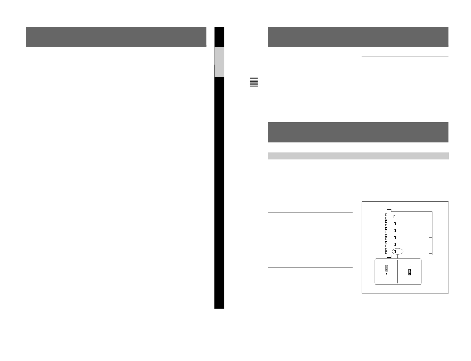
To set the grounded mode, insert the jumper-pins into
the ON slot and the center slot. To set the floating
mode, insert the jumper-pins into the OFF slot and the
center slot.
The factory preset is grounded mode.
Floating mode is useful for rejecting common mode
noise.
Overview
Functions
The BKM-48X HD Analog Input Expansion Adaptor
is a video signal input adaptor for BVM-Series and
HDM-Series video monitors.
When installed in an input option slot on the rear panel
of the video monitor, it provides video input and
output connectors for the monitor.
Expansion of Analog Composite Inputs
The BKM-48X is not equipped with decoders, but if
decoder adaptors are installed in other input option
slots, you can use them to decode analog composite
signals input to the BKM-48X.
Expansion of analog component inputs is also
possible.
Analog Input and Output Signal
Connectors
The BKM-48X is equipped with six input and six
output connectors. You can input two Y/R–Y/B–Y,
RGB or YC signals, or six analog composite signals
to the input connectors. The types of analog
composite signals that may be input vary depending
on the input adaptors installed in other input option
slots (see page 4(E)).
Floating System
Each input connector can be selected to either
floating or grounded mode by the switches on the
board (SW1 to SW6, shown in the figure on the right
column).
Grounded mode Floating mode
About the Software Version of the Monitor
Installed
The following software versions are necessary to use
the BKM-48X with your monitor.
• For BVM-E, -F series monitor : Version 1.30 or later
• For BVM-G series monitor : Version 1.00 or later
• For HDM series monitor : Version 1.10 or later
If the software version of your monitor is previous to
those listed above, contact your nearest Sony dealer or
Sony service facility for an upgrade.
3(E)
Using the Input and Output
Connectors
For information about installing the BKM-48X in a video
monitor input option slot, see “Installing into Video
Monitors” (page 7 (E)).
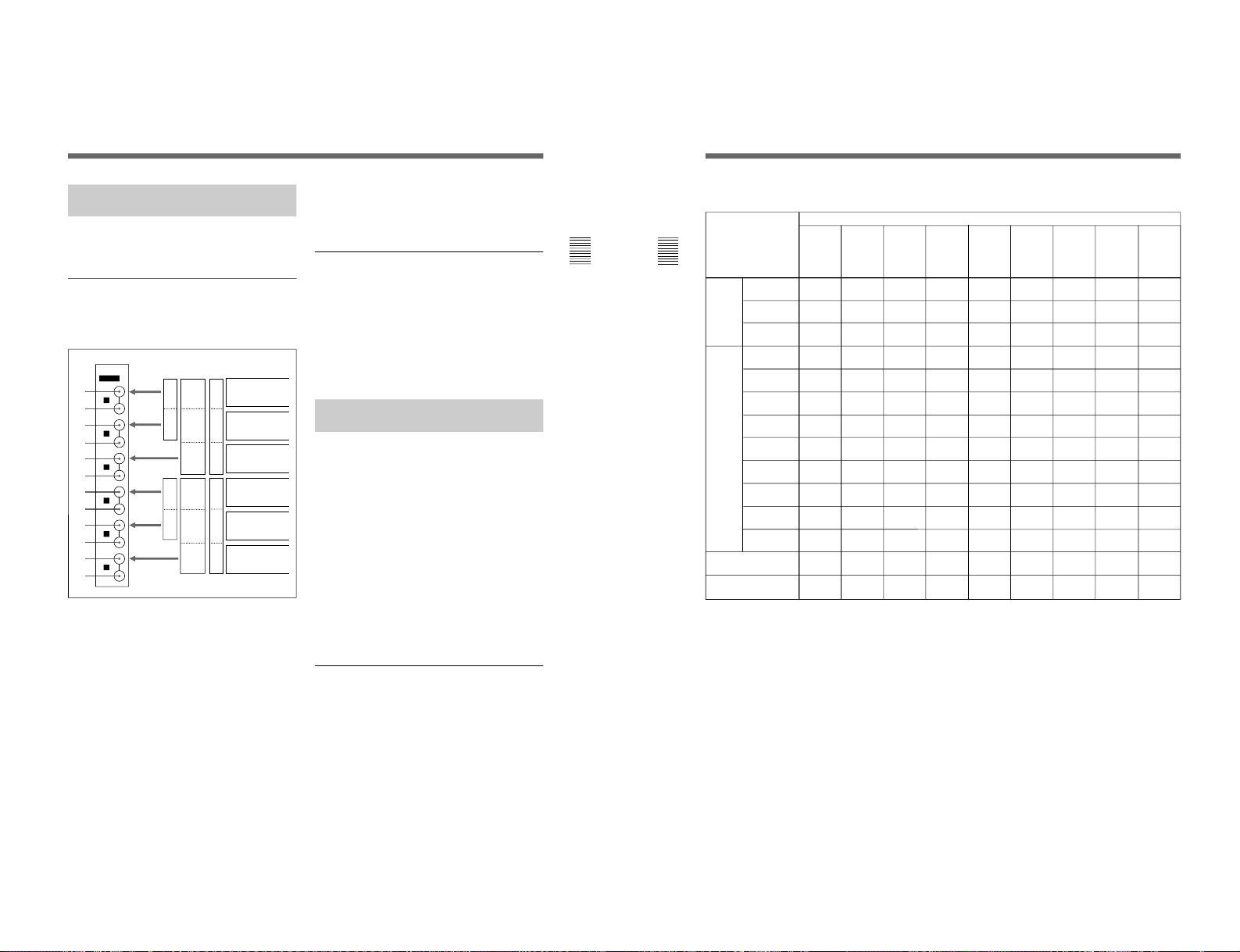
Configuration of Input/Output Connectors
and Signals that may be Input
The configuration of the input and output connectors
and the signals that may be input are shown below.
Input of analog composite signals
You can input analog composite signals to connectors
1, 3, 5, 7, 9, and !¡. You can obtain loopthrough output of those signals from connectors 2,
4, 6, 8, 0, and !™, respectively. If you do not
wish to use loop-through output, attach 75-ohm
terminators to connectors 2, 4, 6, 8, 0, and !™.
Input of Y/R–Y/B–Y, RGB, or YC signals
When inputting Y/R–Y/B–Y or RGB signals, you can
input Y or G signals to connectors 1 and 7, B–Y or
B signals to connectors 3 and 9, and R–Y or R
signals to connectors 5 and !¡.
When inputting YC signals, you can input Y signals to
connectors 1 and 7, and C signals to connectors 3
and 9. (Connectors 5 and !¡ are not used).
You can obtain loop-through output of the above signals
G
B
R
Y
B–Y
R–Y
Y
C
G
B
R
Y
B–Y
R–Y
Y
C
Analog
composite
signals
Analog
composite
signals
Analog
composite
signals
Analog
composite
signals
Analog
composite
signals
Analog
composite
signals
from connectors 2, 4, 6, 8, 0, and !™,
respectively. If you do not wish to use loop-through
output, attach 75-ohm terminators to connectors 2,
4, 6, 8, 0, and !™.
Assigning Input Signals to Connectors
Before inputting signals to the BKM-48X, you must
specify the type and format of the signal that will be
input to each connector. To assign input signals to
each connector, use the on-screen INPUT
CONFIGURATION menu of your video monitor.
For information about using the INPUT CONFIGURATION
menu, refer to the manual of your video monitor.
Combination of Multiple
Adaptors
You can configure an input and output connector panel
by installing any combination of adaptors in the input
option slots on the rear panel of the video monitor.
By combining adaptors of different types, you gain
access to a wider range of input signals than would be
possible with a single adaptor type. The input signals
made available by different combinations of adaptor
types are shown in the table on the next page.
The number of input option slots varies with video
monitors, and to specify signal types for each input
connector, use the on-screen INPUT
CONFIGURATION menu of your video monitor.
For information about the input option slots and using the
INPUT CONFIGURATION menu, refer to the manual of
your video monitor.
Internal Connections between Decoders
When you install a decoder adaptor (BKM-20D/21D/
24N/25P/26M/27T), it is connected to the other
adaptors installed in your video monitor’s input option
slots over an internal bus. Therefore, if you install a
decoder adaptor for a given signal, you can decode that
signal even when it is input to another adaptor.
IN
OUT
ANALOG
IN
OUT
IN
OUT
IN
OUT
IN
OUT
IN
OUT
4
5
6
1
2
3
1
3
5
7
9
!¡
2
4
6
8
0
!™
4(E)
6
BKM-26M
PAL-M
Decoder
Adaptor
r: Independent input possible
®: Input possible when used with decoder adaptor
Combinations of adaptors and input signals made available
Y/C
PAL
BKM-21D
SDI Multi
Decoder
Adaptor
Adaptor name
BKM-24N
NTSC
Decoder
Adaptor
BKM-25P
PAL
Decoder
Adaptor
BKM-27T
TriStandard
Decoder
Adaptor
BKM-22X
SDI Input
Expansion
Adaptor
BKM-28X
Analog
Input
Expansion
Adaptor
Composite
NTSC
Composite
PAL
Composite
NTSC
Composite
PAL
Composite
PAL-M
Component
525/625
Composite
SECAM
Y/R–Y/B–Y
525/625
RGB
525/625
Y/C
NTSC
Serial
digital
input
Analog
input
r
r
r
r
r
®
®
r
r
r
®
®
®
r
r
r
®
r
®
®
r
r
r
®
®
r
®
r
r
r
r
®
r
r
r
r
r
®
®
®
®
®
®
®
r
r
®
®
®
®
r
r
®
®
®
®®
®
BKM20D SDI
4:2:2
Decoder
Adaptor
r
®
®
®
r
r
Number of analog
input
Number of digital
inputs
Y/C
PAL-M
3366 63
3
3–
–
–
–3
®
®
®
®r
®
®
®
BKM-48X
HD Analog
Input
Expansion
Adaptor
®
®
®
®
r
r
®
®
6
–
®
Using with BVM-Series Video Monitors
1-3(E)
1-4(E)
5(E)
OFF
ON
OFF
ON
SW1
SW2
SW3
SW4
SW5
SW6
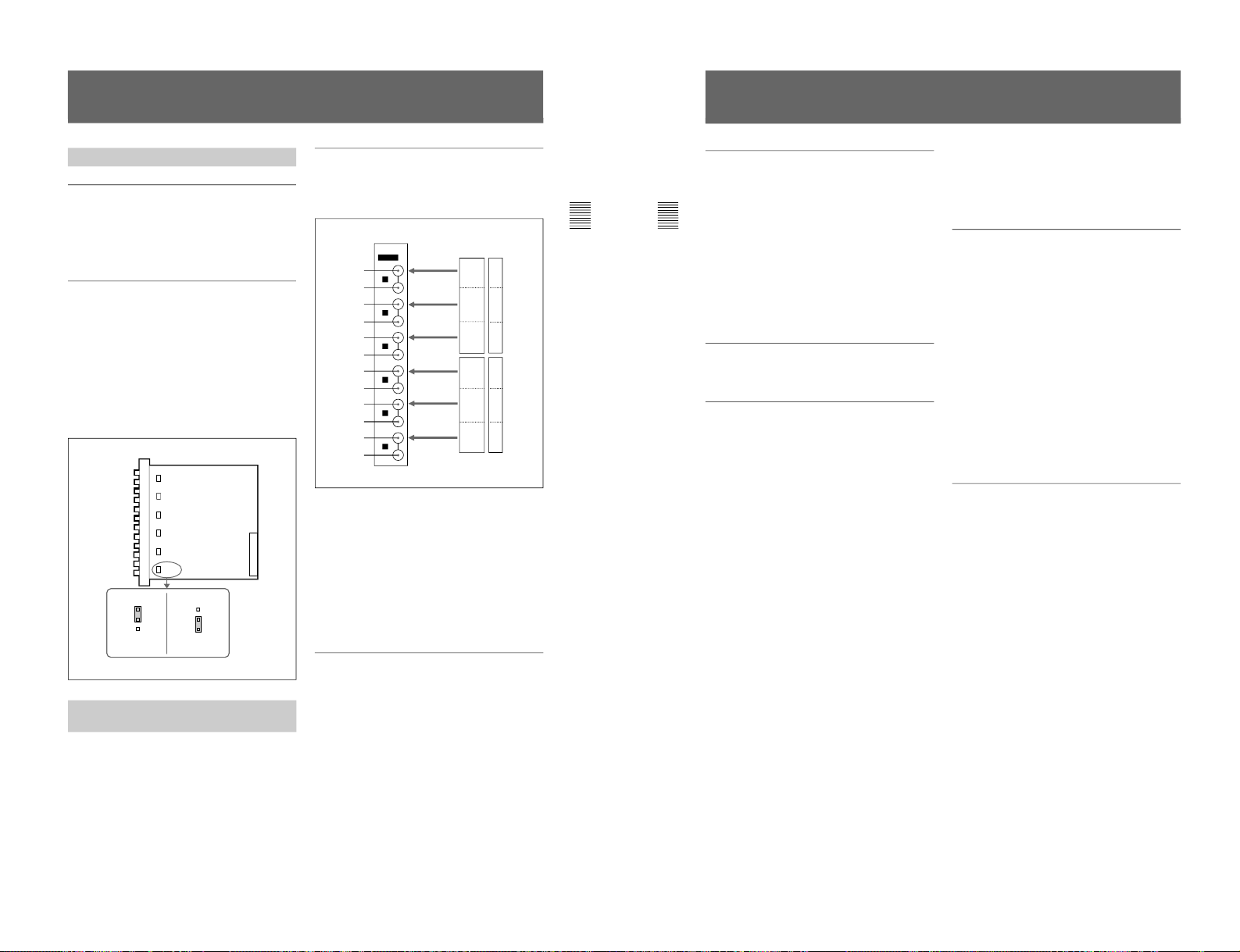
Configuration of Input/Output Connectors
and Signals that may be Input
The configuration of the input and output connectors
and the signals that may be input are shown below.
Input of Y/P
B/PR
or GBR signals
When inputting Y/P
B/PR
or GBR signals, you can input
Y or G signals to connectors 1 and 7, P
B
or B
signals to connectors 3 and 9, and P
R
or R signals to
connectors 5 and !¡.
You can obtain loop-through output of the above
signals from connectors 2, 4, 6, 8, 0, and !™,
respectively. If you do not wish to use loop-through
output, attach 75-ohm terminators to connectors 2,
4, 6, 8, 0, and !™.
Assigning Input Signals to Connectors
Before inputting signals to the BKM-48X, you must
specify the type and format of the signal that will be
input to each connector. To assign input signals to
each connector, use the on-screen INPUT
CONFIGURATION menu of your video monitor.
For information about using the INPUT CONFIGURATION
menu, refer to the manual of your video monitor.
IN
OUT
ANALOG
IN
OUT
IN
OUT
IN
OUT
IN
OUT
IN
OUT
4
5
6
1
2
3
Using with HDM-Series Video Monitors
Functions
Analog Input and Output Signal
Connectors
The BKM-48X is equipped with input and output
connectors for two signal paths. You can input Y/P
B/PR
or GBR signals to the input connectors.
Floating System
Each input conector can be selected to either floating
or grounded mode by the switches on the board (SW1
to SW6, shown in the figure below).
To set the grounded mode, insert the jumper-pins into
the ON slot and the center slot. To set the floating
mode, insert the jumper-pins into the OFF slot and the
center slot.
The factory preset is grounded mode.
Floating mode is useful for rejecting common mode
noise.
Using the Input and Output
Connectors
For information about installing the BKM-48X in a video
monitor input option slot, see “Installing into Video
Monitors” (page 7 (E)).
G
B
R
Y
P
B
P
R
G
B
R
Y
P
B
P
R
1
3
5
7
9
!¡
2
4
6
8
0
!™
Grounded mode Floating mode
6(E)
Aperture compensation (Y/R–Y/B–Y)
Off: 0 dB
On: 2 to 6 dB (5 MHz)
Return loss 43 dB min. (10 MHz, 75-ohm
terminated)
Signal Characteristics (Using with HDMSeries Video Monitors)
Analog component (Y/P
B/PR
, GBR) signals
Signal level
Y/P
B/PR
Y: 1 Vp-p ±6 dB
P
B
: 0.7 Vp-p ±6 dB
P
R
: 0.7 Vp-p ±6 dB
G/B/R 1 Vp-p ±6 dB (sync on G)
Frequency characteristics
Y 50 Hz to 30 MHz ±1dB
P
B/PR
50 Hz to 30 MHz ±1dB
G/B/R 50 Hz to 30 MHz ±1dB
Chrominance signal/luminance signal
Delay time error
30 nsec max.
Gain error 5% max.
Return loss 43 dB min. (10 MHz, 75-ohm
terminated)
Accessory Supplied
Installation Manual (1)
Design and specifications are subject to change
without notice.
General
Power requirements +5 V, ±6 V, ±15 V (supplied
from the monitor)
Power consumption 6W
Recommended operating temperature
20°C to 30°C (68°F to 86°F)
Permissible operating temperature
0°C to 35°C (32°F to 95°F)
Operating humidity 0% to 90% (no condensation)
Maximum external dimensions (w/h/d)
25 × 256 × 245 mm
(
31
/32 × 101/8 × 93/4 inches)
Mass 660g (1lb 7 oz)
Input/Output Connectors
BNC × 6, high impedance, with loop-through output
Signal Characteristics (Using with BVMSeries Video Monitors)
Analog composite signals
Signal level 1 Vp-p +3 dB/–6 dB
Return loss 43 dB min. (10 MHz, 75-ohm
terminated)
YC signals
Signal level Y: 1 Vp-p ±6 dB
C: 0.286 Vp-p ±6 dB (NTSC
burst signal level)
0.3 Vp-p ±6 dB (PAL burst
signal level)
Analog component (Y/R–Y/B–Y, RGB) signals
Signal level
Y/R–Y/B–Y Y: 1 Vp-p ±6 dB
R–Y: 0.7 Vp-p ±6 dB
B–Y: 0.7 Vp-p ±6 dB
R/G/B 1 Vp-p ±6 dB (sync on G)
Frequency characteristics
Y 50 Hz to 10 MHz ±1dB
R–Y/B–Y 50 Hz to 6 MHz ±1dB
R/G/B 50 Hz to 30 MHz ±1dB
Chrominance signal/luminance signal
Delay time error
30 nsec max.
Gain error 5% max.
Specifications
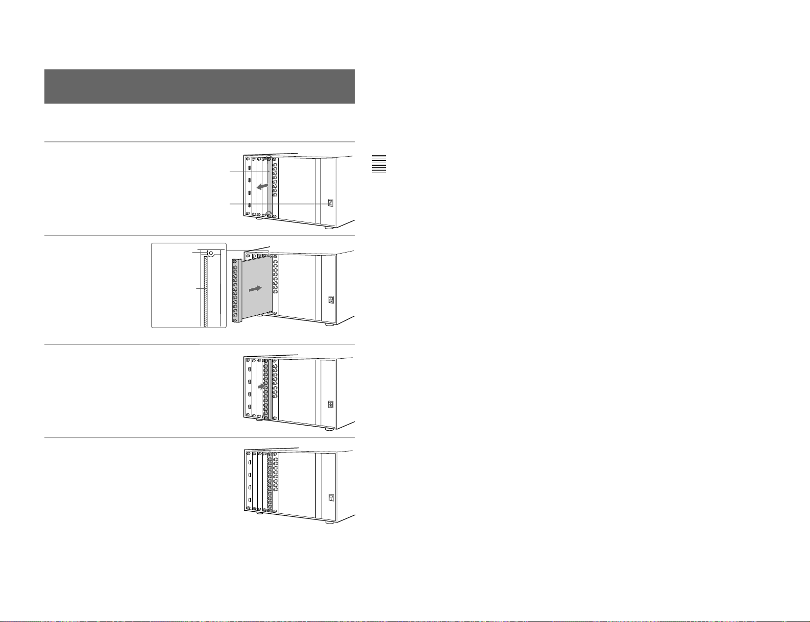
7(E)
1
Remove the cover of an input
option slot on the rear panel
of your video monitor.
2
Insert the adaptor below the
alignment mark on the left of
the upper screw hole of the slot.
3
Push the adaptor in until it is
firmly seated in the connector
inside your video monitor.
4
Tighten the both screws to
retain the adaptor.
Installing into Video Monitors
Check to be sure that the
video monitor’s MAIN POWER
switch is off.
Cover of an input option slot
Alignment mark
Always turn your video monitor’s MAIN POWER
switch off before installing or removing adaptor.
The BKM-48X can be installed in any input option
slot.
Insert the adaptor
below the mark.
The material contained in this manual consists of
information that is the property of Sony Corporation and is
intended solely for use by the purchasers of the equipment
described in this manual.
Sony Corporation expressly prohibits the duplication of any
portion of this manual or the use thereof for any purpose
other than the operation or maintenance of the equipment
described in this manual without the express written
permission of Sony Corporation.
Le matériel contenu dans ce manuel consiste en
informations qui sont la propriété de Sony Corporation et
sont destinées exclusivement à l’usage des acquéreurs de
l’équipement décrit dans ce manuel.
Sony Corporation interdit formellement la copie de quelque
partie que ce soit de ce manuel ou son emploi pour tout
autre but que des opérations ou entretiens de l’équipement
à moins d’une permission écrite de Sony Corporation.
Das in dieser Anleitung enthaltene Material besteht aus
Informationen, die Eigentum der Sony Corporation sind,
und ausschließlich zum Gebrauch durch den Käufer der in
dieser Anleitung beschriebenen Ausrüstung bestimmt sind.
Die Sony Corporation untersagt ausdrücklich die
Vervielfältigung jeglicher Teile dieser Anleitung oder den
Gebrauch derselben für irgendeinen anderen Zweck als die
Bedienung oder Wartung der in dieser Anleitung
beschriebenen Ausrüstung ohne ausdrückliche schriftliche
Erlaubnis der Sony Corporation.
1-5(E)

SECTION 2
SERVICE INFORMATIONS
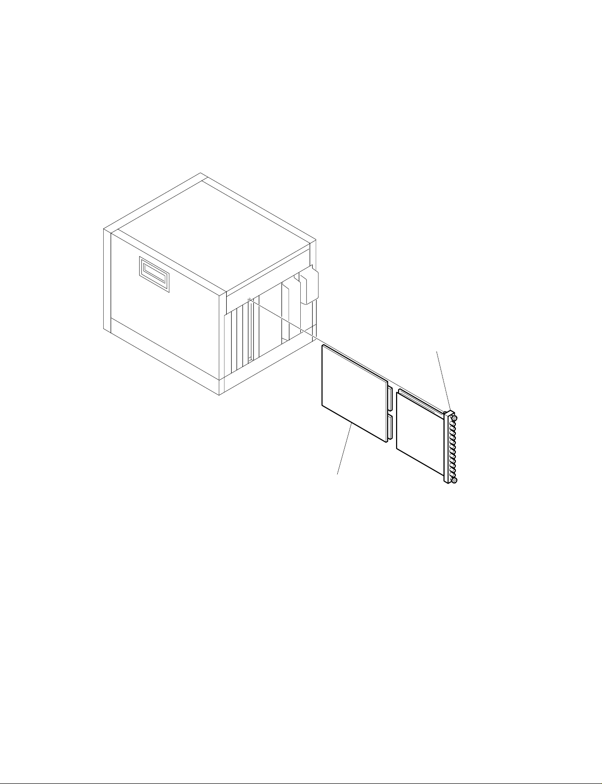
2-1. BHA BOARD REMOVAL AND CHECK
1 BHA board
(Loosen two panel stopper screws.)
2 Extension board (Z board)
* Insert the Z board into the slot.
And insert the BHA board into the connector on the Z board.
2-1(E)


SECTION 3
CIRCUIT ADJUSTMENTS
The BKM-48X is an optional board for the HDM series, BVM
series, and therefore will not operate on its own. To adjust
and measure it, BKM-48X must be mounted with the HDM
series monitor, BVM series monitor . The HDM series monitor, BVM series monitor used in these adjustments should
satisfy the respective specifications.
3-1. PREPARATIONS FOR BHA BOARD
ADJUSTMENTS
3-1-1. When mounting to BVM
Set as follows in the INPUT CONFIGURATION menu of
the SETUP menu.
• 01 CH
FORMAT ...............RGB
SLOT NO. .............. n (Set to the slot number with the
BHA inserted)
INPUT NO............. 123
SYNC MODE ........ INT
• 02 CH
FORMAT ...............YUV
Same as 01 CH for others
• 03 CH
FORMAT ...............NTSC 0
SLOT NO. .............. n (Set to the slot number with the
BHA inserted)
INPUT NO............. 1
YC SEP .................. COMP
SYNC MODE ........ INT
APERTURE........... OFF
FILTER .................. OFF
CONTROL............. PRESET
H PHASE............... 000
3-1-2. When mounting to HDM
Set as follows in the INPUT CONFIGURATION menu of
the SETUP menu.
• 01 CH
FORMAT ...............GBR
SLOT NO. .............. n (Set to the slot number with the
BHA inserted)
INPUT NO.............123
SYNC MODE ........ INT
• 02 CH
FORMAT ...............YPBPR
Same as 01 CH for others
• 03 CH
FORMAT ...............GBR
INPUT NO.............456
Same as 01 CH for others
• 04 CH
FORMAT ...............YC NTSC 0
Same as 03 CH for others
• 05 CH
FORMAT ...............RGB
INPUT NO............. 456
Same as 01 CH for others
* Mount together with the BKM-24N or BKM-27T.
3-1(E)
 Loading...