

Sony BKM-38H Installation Manual
CONTROLLER ATTACHMENT STAND
BKM-38H
安全のための注意事項を守らないと、火災や
人身事故になることがあります。
このインストレーションマニュアルには、事故を防ぐための重要な注意事
項と製品の取り扱いかたを示してあります。このインストレーションマ
ニュアルをよくお読みのうえ、製品を安全にお使いください。お読みに
なったあとは、いつでも見られるところに必ず保管してください。
INSTALLATION MANUAL
[Japanese/English/French/German/Italian/Spanish]
[Simplified Chinese/Traditional Chinese/Korean]
1st Edition (Revised 1)
日本語
安全のために
警告表示の意味
このインストレーションマニュア
ルおよび製品では、次のような表
示をしています。表示の内容をよ
く理解してから本文をお読みくだ
さい。
下記の注意を守らないと、
火災や感電により死亡や大けがに
つながることがあります。
この表示の注意事項を守らないと、
火災や感電などにより死亡や大け
がなど人身事故につながることが
あります。
この表示の注意事項を守らないと、
事故によりけがをしたり周辺の物
品に損害を与えたりすることがあ
ります。
注意を促す記号
油煙、湯気、湿気、ほこりの多い場所では設
置・使用しない
上記のような場所で設置・使用すると、火災や感電の原因と
なります。取扱説明書に記されている使用条件以外の環境で
の設置・使用は、火災や感電の原因となります。
モニターとスタンドの間に指を挟まない
挟み込まれると、けがの原因となることがあります。
組み立ての際には、モニターの電源を切って
電源プラグを抜く
モニターの電源を接続したまま、本スタンドとの組み立てを
行うと、モニターと本スタンドに電源コードをはさみ、感電
の原因となることがあります。組み立ての際にはモニターの
電源を切り、電源プラグを抜いてください。
行為を禁止する記号
行為を指示する記号
安全のために / 警告
2
指定された接続ケーブルを使
う
この取扱説明書に記されている接続ケー
ブルを使わないと、火災や故障の原因と
なることがあります。
組み立てる際は必ず付属のネ
ジを使う
重いモニターは2 人以上で開
梱・運搬する
モニターは、見た目より重量がありま
す。開梱や運搬は、けがや事故を防ぐた
め、必ず 2人以上で行ってください。1
人で行うと、腰を痛めることがありま
す。
組立て作業は2 人以上で行う
モニターとコントロールユニットを連結
する時は、2 人以上で行ってください。
1 人で行うと、腰を痛めたり、けがの原
因となることがあります。
組み立て作業時に手や指をは
さまない
モニターとコントロールユニットを組み
立てる際、モニターとコントロールユ
ニットの間や、モニターと作業台の間で
手や指をはさみ、けがの原因となること
があります。
違うネジを使用すると、ゆるんだり、外
れたりしてけがの原因となることがあり
ます。
運搬時は、電源コードや接続
コードをはずす
転倒などによるけがの原因となることが
あります。
指定以外の機器には使用しな
い
指定以外の機器を取り付けると、落下、
転倒してけがの原因となることがありま
す。
電源コードや接続コードの上
にスタンドを置いたり、乗り
越えたりしない
断線したり、ショートしたりして火災や
感電の原因となることがあります。
JP
不安定な場所に設置しない
ぐらついた台の上や傾いたところなどに
設置すると、モニターが落ちたり、倒れ
たりしてけがの原因となることがありま
す。また、設置・取付け場所の強度を充
分にお確かめください。
不安定な状態で設置作業をし
ない
必ず水平な場所でモニターを取り付けて
ください。転倒してけがの原因となるこ
とがあります。
注意
3
製品の上に乗らない、重いも
のを載せない
倒れたり、落ちたり、壊れたりして、け
がの原因となることがあります。
改造しない
改造すると強度が低下し、モニターが転
倒してけがの原因となることがありま
す。
シャープエッジには素手で触
れない
機器の開梱、運搬、設置、分解の際はけ
がを防ぐため保護手袋を着用してくださ
い。
注意
4
目次
概要...........................................................................................................................6
特長 ...............................................................................................................6
設置寸法 ........................................................................................................6
部品構成 ........................................................................................................6
組み立て ...................................................................................................................7
スタンドとコントロールユニットを連結する...............................................7
スタンドとモニターを連結する ....................................................................8
お使いになる前に、必ず動作確認を行ってください。故障その他に伴う
営業上の機会損失等は保証期間中および保証期間経過後にかかわらず、
補償はいたしかねますのでご了承ください。
目次
5
概要
特長
BKM-38H は、LCD ビデオモニター PVM-L2300や25型の
業務用ビデオモニター BVM シリーズに、モニターコント
ロールユニット BKM-16R を取り付け可能なスタンドです。
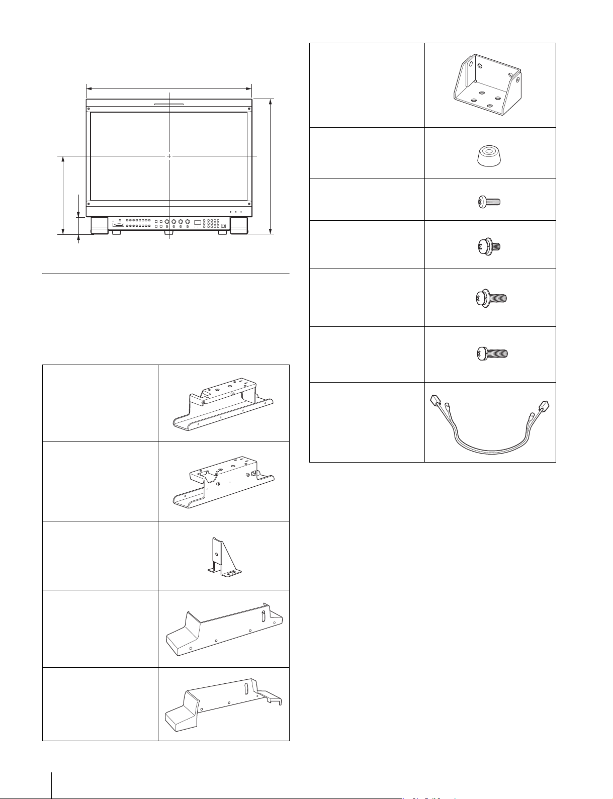
部品構成
BKM-38H は以下の部品で構成されています。組み立てを始
める前に、部品がすべてそろっていることをお確かめくださ
い。
スタンド(右)× 1
モニターとコントロールユニットを連結可能
モニターとコントロールユニット BKM-16R を連結すること
ができます。
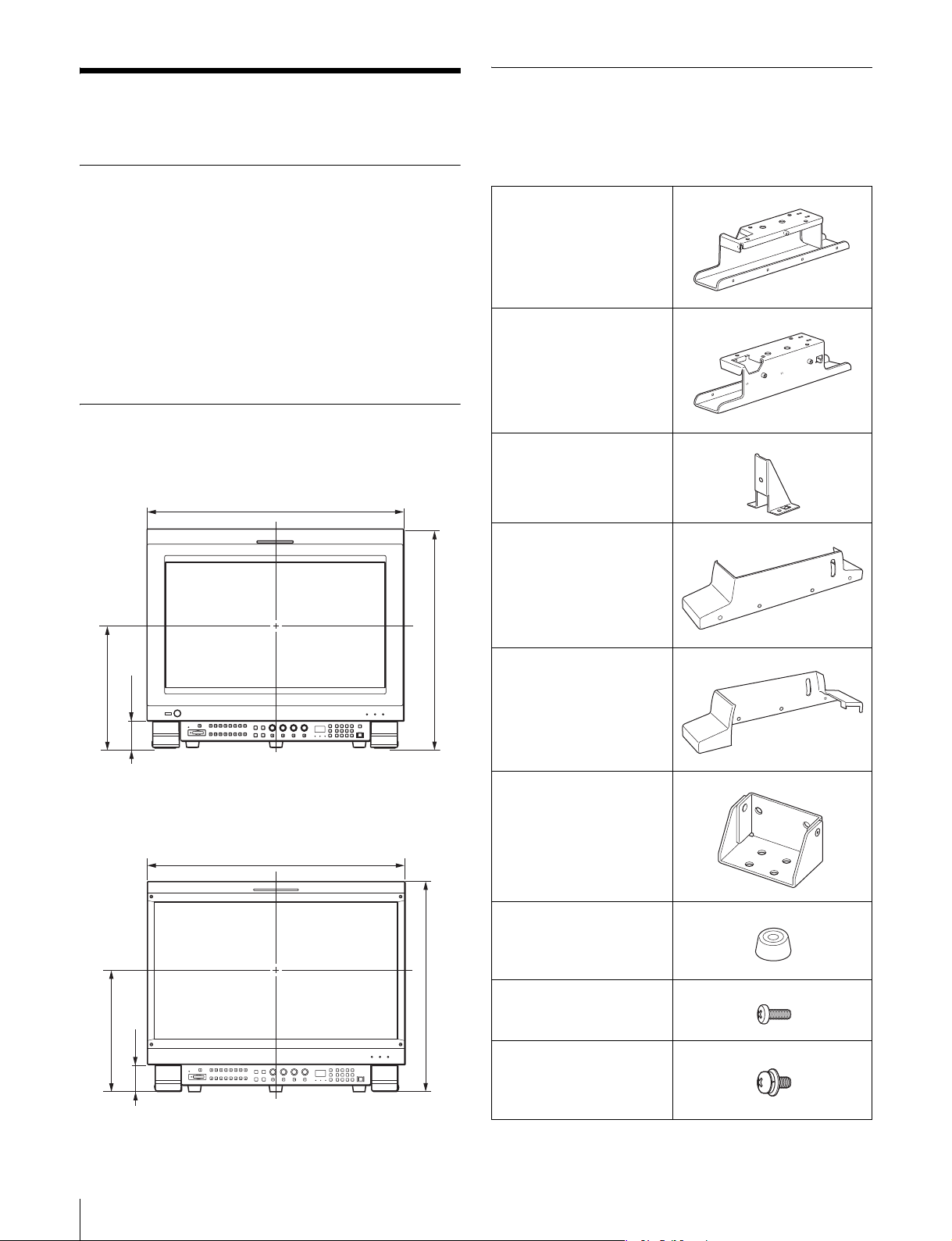
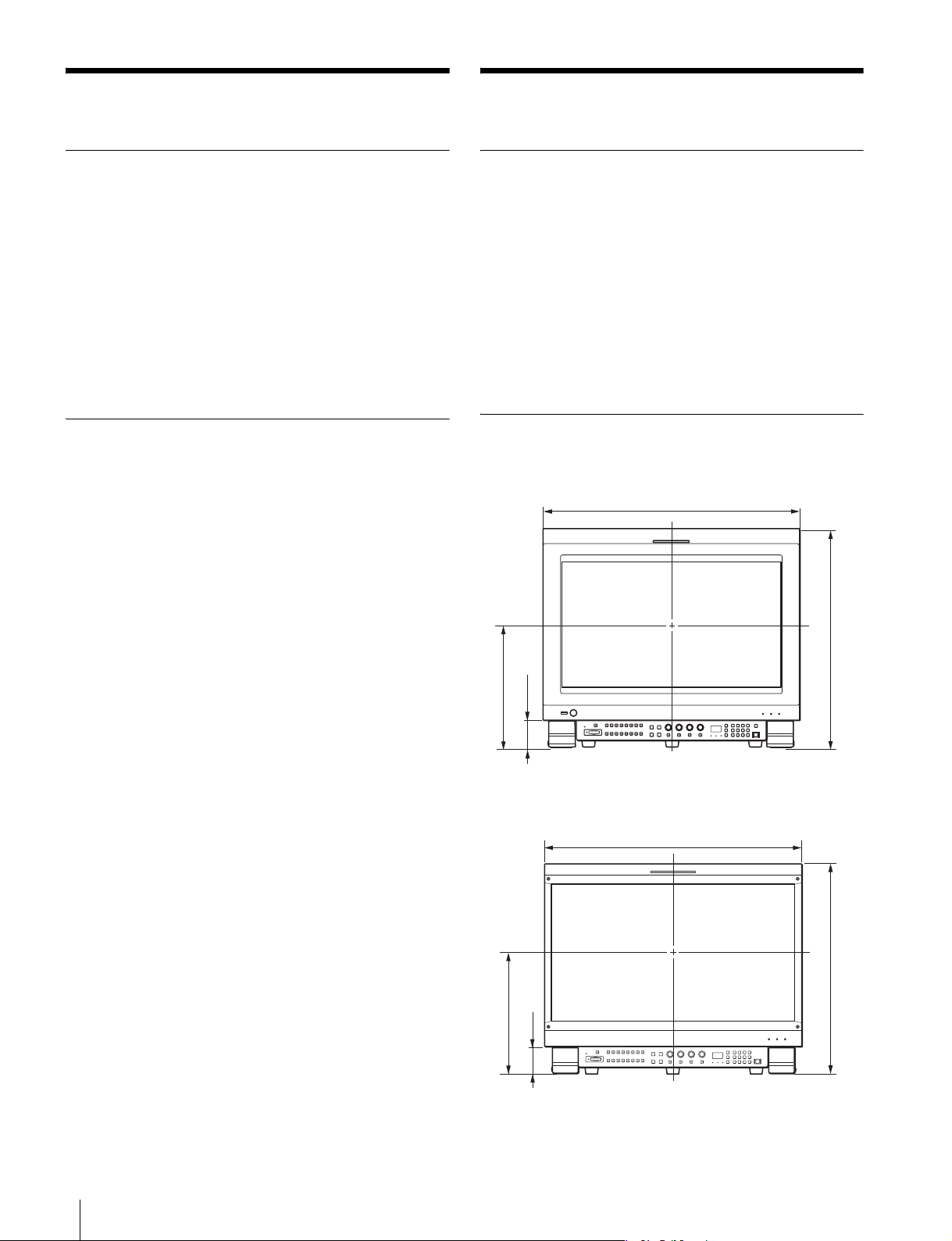
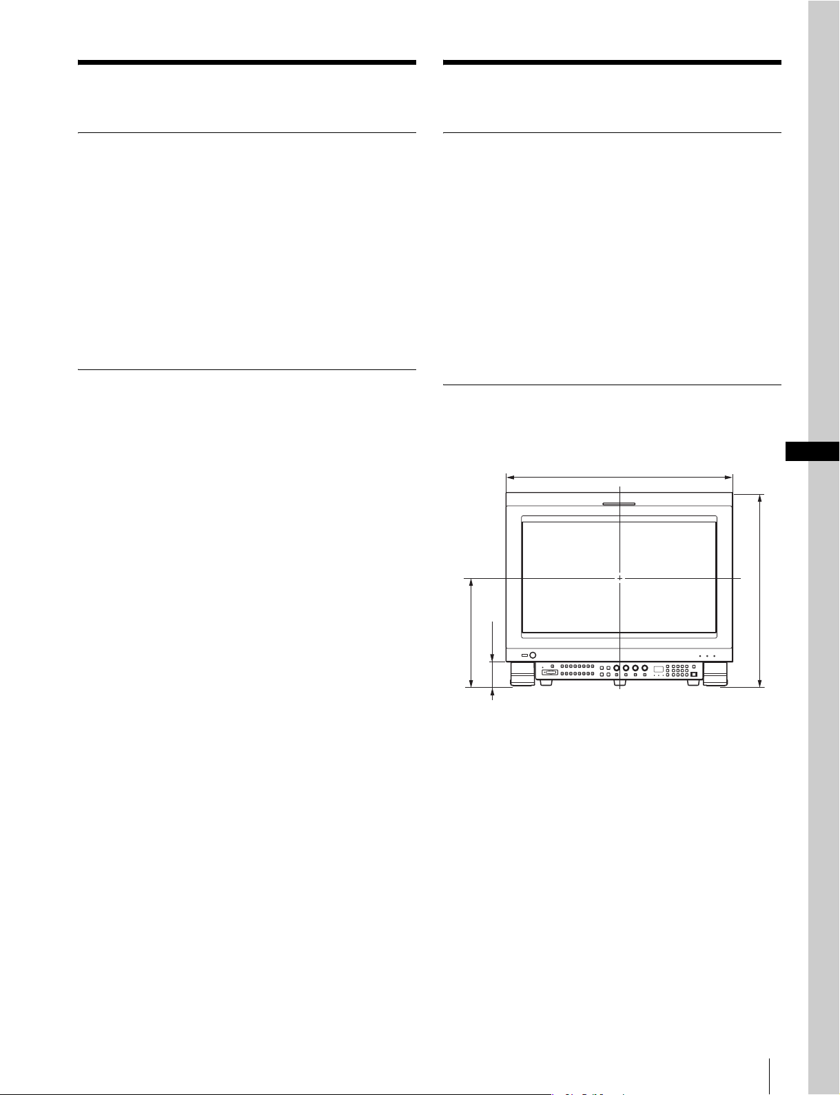
設置寸法
ユニットを取り付けたとき(PVM-L2300 モニター)
565.5
481.3
271.3
61.3
スタンド(左)× 1
プレート× 2
カバー(右)× 1
カバー(左)× 1
ユニットを取り付けたとき(BVM シリーズモニター)
576.0
271.6
61.6
概要
6
単位:mm
469.6
単位:mm
ジョイント× 2
足× 2
ネジ A(3 × 8)× 8
ネジ B(4 × 8)× 6
ネジ C(4 ×16)× 4
ネジ D(4 ×16)× 2
( 平ワッシャーなし)
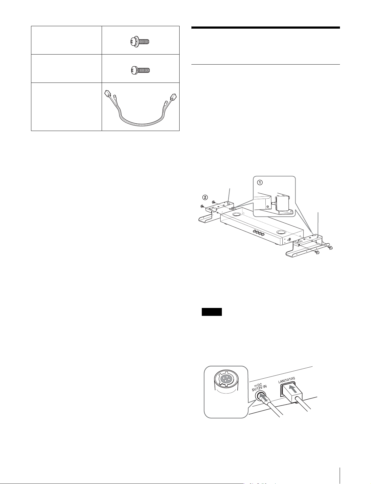
組み立て
スタンドとコントロールユニットを連
接続ケーブル× 1
結する
スタンドを使ってモニターとコントロールユニットを連結す
ることができます。
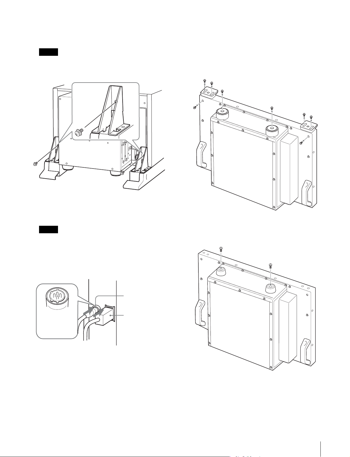
1
1 コントロールユニットをスタンドうしろの突起部分
に押し当てる。
2 ネジ C(4 × 16)2 本ずつを使って、コントロールユ
ニットの両側面にスタンド(左)およびスタンド
(右)を取り付ける。
スタンド(左)
スタンド(右)
ネジ C
2
付属の接続ケーブルを、コントロールユニット背面の
DC5V / 12VIN 端子および LAN(10 / 100)端子に
接続する。
ご注意
DC5V / 12VIN 端子にケーブルをつなぐときは、ケー
ブル両端の凸凹を確認し、必ず凹側をコントロールユ
ニットに接続してください。つなぐときは、ケーブル先
端の形と DC
て、差し込んでください。
凹コネクターを
差し込む
5V /12VIN 端子の形をあわせるようにし
組み立て
7
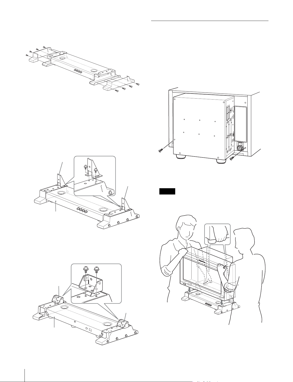
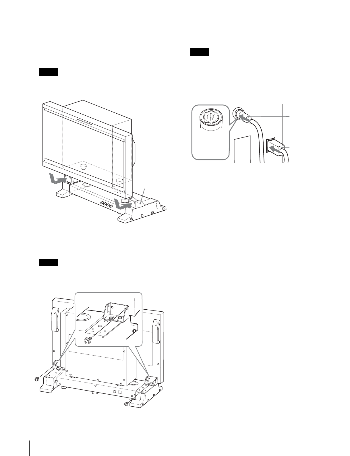
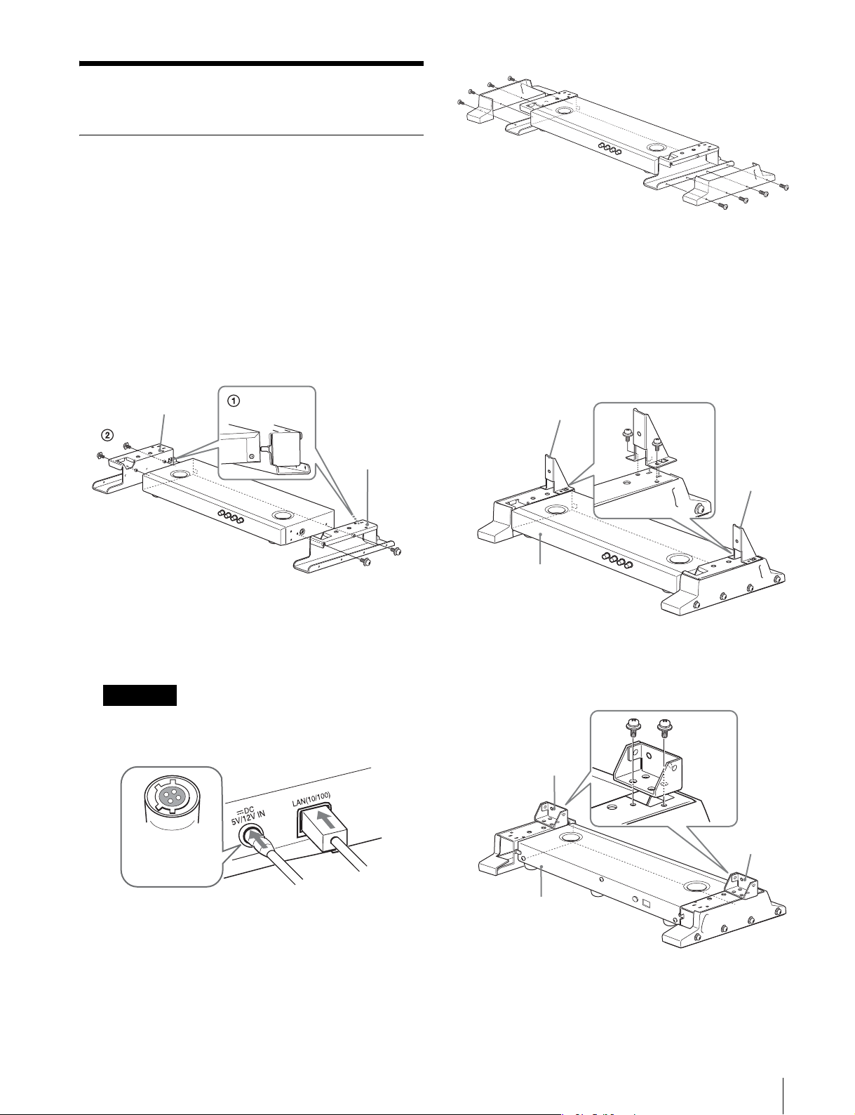
3
ネジ A(3 × 8)4 本ずつを使って、カバー(左)および
カバー(右)をスタンド(左)とスタンド(右)に取り
付ける。
4
PVM-L2300 と BVM シリーズでは手順が異なります。
PVM-L2300 の場合
スタンド(左)およびスタンド(右)のスリットにプ
レートを差し込み、ネジ B(4×8)2 本ずつを使って
固定する。
プレート
ネジ B
ネジ A
スタンドとモニターを連結する
BVM シリーズのモニターについては、「BVM シリーズモニ
ター」(9 ページ)をご覧ください。
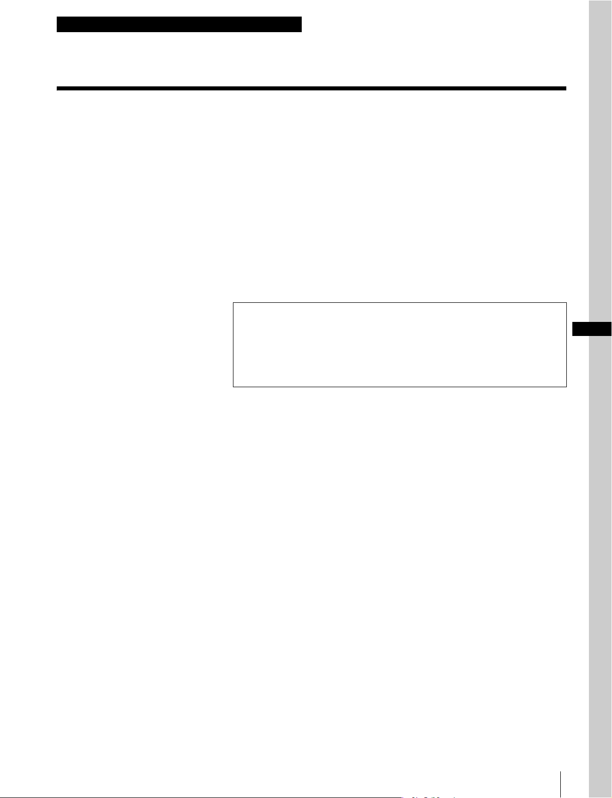
PVM-L2300 モニター
1
モニター裏側のネジ 2 本をはずす。
プレート
コントロールユニット
前面
BVM シリーズの場合
スタンド(左)およびスタンド(右)にジョイントを載
せて、ネジ B(4 × 8)2 本ずつを使って固定する。
ネジ B
ジョイント
ジョイント
2
モニターの前足をスタンド前側の溝に差し込む。
ご注意
プレートにモニターをぶつけないでください。モニター
に傷がつくおそれがあります。
8
コントロールユニット
背面
組み立て
3
付属のネジ B(4 × 8)2 本を使って、モニターとスタン
ドを固定する。
ご注意
モニターとスタンドをネジ B で固定するときは、モニ
ターが動かないように支えてください。
ネジ B
BVM シリーズモニター
1
モニターを逆さにする。
2
モニター底面の足 4 個と、モニター背面のネジ(左右 1 か
所ずつ)をはずす。
4
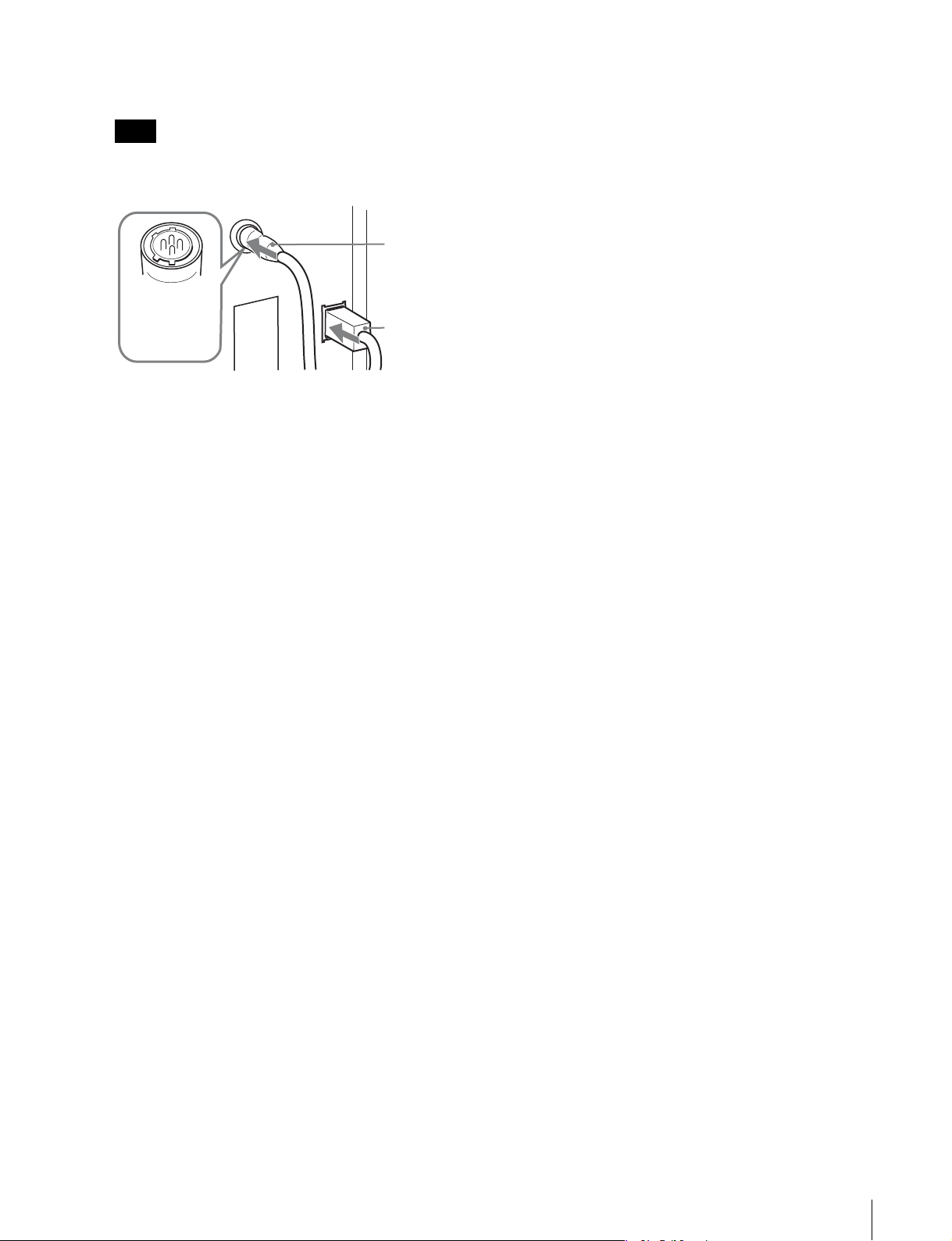
接続ケーブルのコネクターを、モニター側面の DC5V
OUT
端子および LAN(10 / 100)端子に接続する。
ご注意
DC5VOUT 端子にケーブルをつなぐときは、ケーブル
両端の凸凹を確認し、必ず凸側をモニターに接続してく
ださい。つなぐときは、ケーブル先端の形と DC5V
OUT 端子の形を合わせるようにして、差し込んでくだ
さい。
DC5VOUT
端子
凸コネクターを
差し込む
LAN(10 / 100)
端子
3
ネジ D(4 × 16)を使って、付属の足 2 個をモニター底面
に取り付ける。
ネジ D
組み立て
9
4
モニターを元の向きに戻し、スタンドを取り付けたコン
トロールユニットの上にモニターを載せる。
6
接続ケーブルのコネクターを、モニター側面の DC5V
OUT 端子および LAN(10 / 100)端子に接続する。
モニター背面にジョイントを押し当てるようにして載せ
てください。
ご注意
ジョイントにモニターをぶつけないでください。モニ
ターに傷がつくおそれがあります。
ジョイント
ご注意
DC5VOUT 端子にケーブルをつなぐときは、ケーブル
両端の凸凹を確認し、必ず凸側をモニターに接続してく
ださい。つなぐときは、ケーブル先端の形と DC5V
OUT 端子の形を合わせるようにして、差し込んでくだ
さい。
DC5VOUT
端子
凸コネクターを
差し込む
LAN
(10 / 100)
端子
5
ネジ B(4 × 8)2 本を使って、モニターとスタンドを固
定する
ご注意
モニターとスタンドをネジ B で固定するときは、モニ
ターが動かないように支えてください。
ネジ B
10
組み立て
English
Before operating the unit, please read this manual
thoroughly and retain it for future reference.
Table of Contents
Precautions ..........................................................................12
On Safety ..................................................................................12
On Installation...........................................................................12
Overview...............................................................................12
Features.....................................................................................12
Dimensions ...............................................................................12
Components ..............................................................................13
Assembly..............................................................................14
Joining the Stand and the Control Unit.....................................14
Joining the Stand and the Monitor............................................15
Note
Always verify that the unit is operating properly before use. SONY WILL NOT BE
LIABLE FOR DAMAGES OF ANY KIND INCLUDING, BUT NOT LIMITED TO,
COMPENSATION OR REIMBURSEMENT ON ACCOUNT OF THE LOSS OF
PRESENT OR PROSPECTIVE PROFITS DUE TO FAILURE OF THIS UNIT,
EITHER DURING THE WARRANTY PERIOD OR AFTER EXPIRATION OF THE
WARRANTY, OR FOR ANY OTHER REASON WHATSOEVER.
GB
Table of Contents
11
Precautions
Overview
On Safety
• Do not install the attachment stand in a location near a
heat source, such as a radiator or air duct, or in a place
subject to excessive dust or humidity.
• Be careful not to catch your finger between the monitor
and the attachment stand.
• When you assemble the attachment stand, turn off the
monitor power before unplugging the cable. If you attach
the attachment stand with the monitor is power on, the
cable may become trapped between the monitor and the
attachment stand, and this may lead to electric shock.
On Installation
• When you unpack, carry, attach or disassemble the
attachment stand, do so with the help of another person,
to avoid personal injury.
• Install the attachment stand on a steady table. If the
attachment stand is installed on a wobbly or sloping
surface, the monitor may full off and may cause personal
injury. Make sure that the installation location is
sufficiently strong.
• The use of connecting cables other than those supplied
may lead to fire and/or other damage.
• The use of screws other than those supplied may lead to
injury, because they may become loose or fall out.
• To carry the monitor, disconnect the connecting cables,
to avoid accidents or personal injury.
• The attachment stand is designed for use with the
monitor. Never use it for another purpose. If you do, it
may cause personal injury.
• Be careful not to snag the power cord or connecting cord
on the attachment stand, and do not step over them,
which could result in disconnection or electric shock.
• Do not climb on the attachment stand or place anything
heavy on it, as this may cause you to fall and injure
yourself or the monitor to crash to the floor.
• If you disassemble or modify the attachment stand, it
may lead to personal injury.
• Do not touch any sharp points of the attachment stand
with bare hands. When you unpack, carry, attach, or
disassemble the attachment stand, wear protective gloves
to avoid injury.
Features
The BKM-38H Controller Attachment Stand is an
attachment stand for joining a Sony PVM-L2300 LCD
Video Monitor or a Sony 25-type professional video
monitor of the BVM series and a Sony BKM-16R Monitor
Control Unit.
Joining the monitor and the control unit
The BKM-38H is for joining a monitor and a BKM-16R
control unit.
Dimensions
When the unit is attached (PVM-L2300 monitor)
3
565.5 (22
/2)
/4)
1
3
61.3 (2
271.3 (10
When the unit is attached (BVM series monitors)
576.0 (22
/4)
/2)
3
1
/8)
481.3 (19)
Unit: mm (inches)
3
/4)
/2)
1
469.6 (18
Precautions / Overview
12
61.6 (2
271.6 (10
Unit: mm (inches)
Components
The BKM-38H consists of the components mentioned
below. Make sure that you have all the components before
beginning assembly.
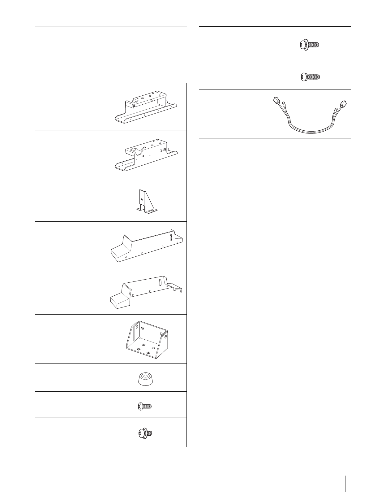
Right stand (1)
Left stand (1)
Plate (2)
Screws C (4 × 16) (4)
Screws D (4 × 16) (2)
(without flat washer)
Connecting cable (1)
Right cover (1)
Left cover (1)
Joints (2)
Legs (2)
Screws A (3 × 8) (8)
Screws B (4 × 8) (6)
Overview
13
Assembly
Joining the Stand and the Control
Unit
You can join a control unit to a monitor, using the
attachment stand.
1
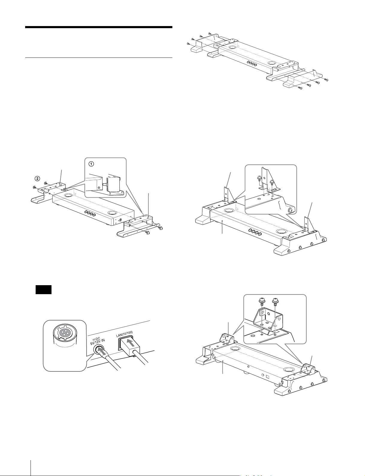
1 Fit the control unit into the projection of the
attachment stand to join them together.
2 Attach the left and right stands to the sides of the
control unit, using two screws C (4 × 16) each.
Left stand
Right stand
Screw C
2
Connect the supplied connecting cable to the DC 5V/
12V IN and LAN (10/100) connectors on the rear panel
of the control unit.
Note
4
Attach the plates or joints to the stands to suit the
models.
For PVM-L2300 monitor
Engage the notches of the left and right stands in the
projections on the bottom of the plates and fix them
securely using two screws B (4 × 8) each.
Plate
Screw B
Front of the
control unit
For BVM series monitors
Place the joints on the left and right stands and fix them
securely using two screws B (4 × 8) each.
Screw A
Plate
Be sure to plug the female connector of the cable onto
the DC 5V/12V IN connector on the control unit.
Connect the
female connector
to the control unit.
3
Attach the left and right covers to the stands, using four
screws A (3 × 8) each.
Assembly
14
Screw B
Joint
Joint
Rear of the
control unit
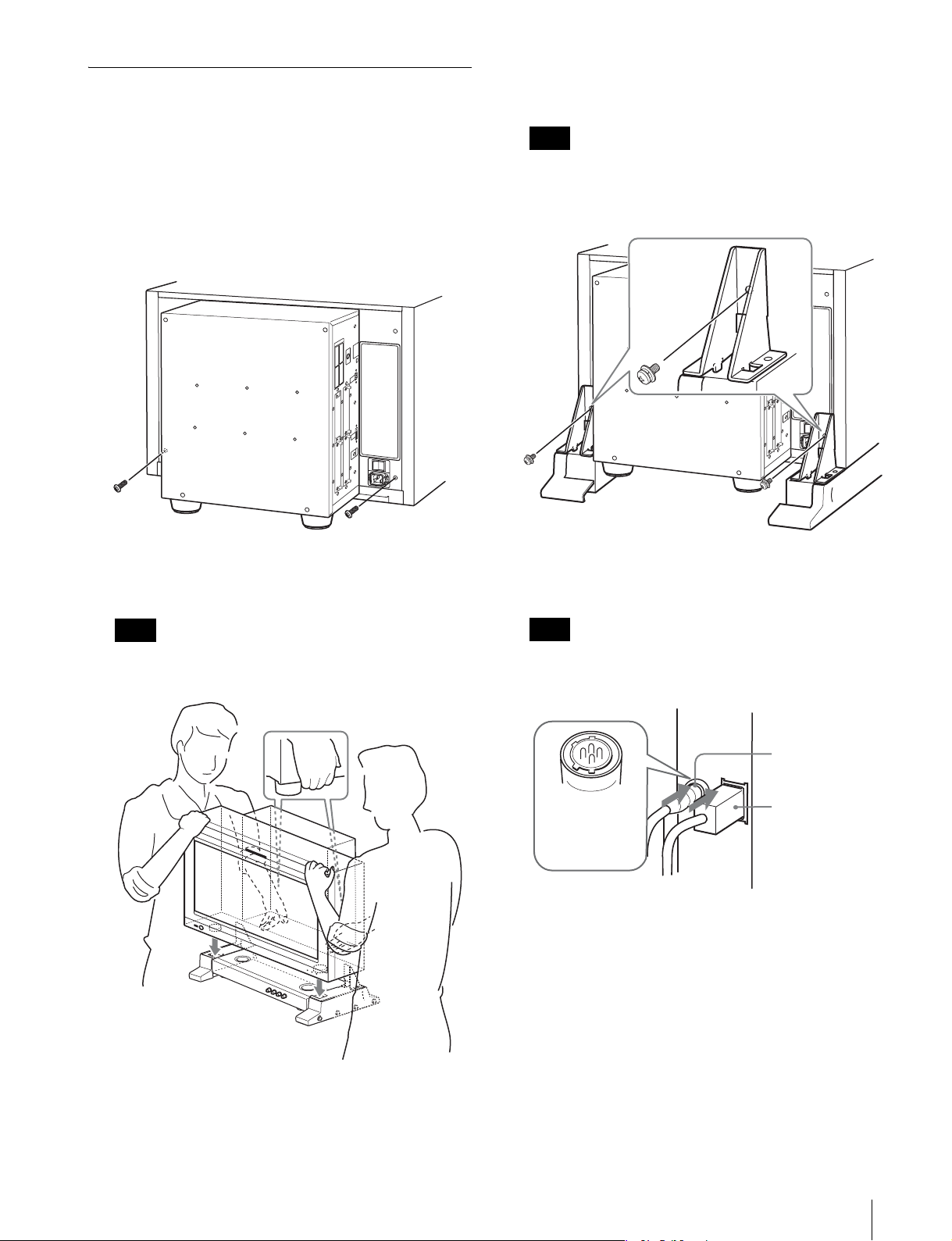
Joining the Stand and the Monitor
3
Attach the stands to the monitor, using two screws B (4
× 8).
For BVM series monitors, see “ BVM series monitors”
(page 16).
PVM-L2300 monitor
1
Remove two of the screws on the back of the monitor.
2
Fit the front stands of the monitor into the front hole of
the attachment stand.
Note
When you fasten screws B to attach the stand to the
monitor, hold the monitor securely against the
mounting surface.
Screw B
4
Plug the connecting cable into the DC 5V OUT and
LAN (10/100) connectors at the side of the monitor.
Note
Protect the monitor from scratches as you carry it
around the plate.
Note
Be sure to plug the male connector of the cable into the
DC 5V OUT connector on the monitor.
DC 5V OUT
connector
Plug the male
connector into
DC 5V OUT on
the monitor.
LAN (10/100)
connector
Assembly
15
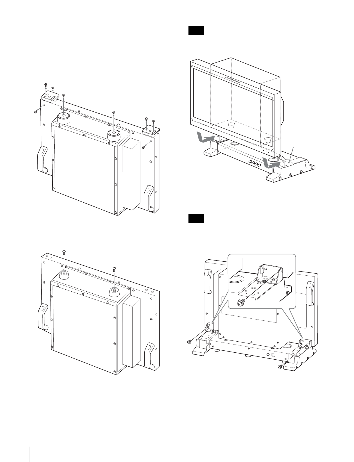
BVM series monitors
Note
1
Turn the monitor upside down.
2
Remove the four legs from the bottom of the monitor,
and remove both left and right screws from the rear of
the monitor.
Protect the monitor from scratches as you manipulate
it around the joints.
Joint
5
Secure the monitor to the stand, using two screws B (4
× 8).
3
Attach the supplied two legs to the bottom of the
monitor, using screws D (4 × 16).
Screw D
Note
When you fasten screws B to secure the monitor to the
stand, hold the monitor securely against the mounting
surface.
Screw B
4
Turn the monitor upright and place the monitor on the
control unit with the stands attached.
Fit the rear of the monitor into the joints to join them
together.
Assembly
16
6
Plug the connecting cable into the DC 5V OUT and
LAN (10/100) connectors at the side of the monitor.
Note
Be sure to plug the male connector of the cable into the
DC 5V OUT connector on the monitor.
DC 5V OUT
connector
Plug the male
connector into
DC 5V OUT on
the monitor.
LAN (10/100)
connector
Assembly
17
Français
Avant d’utiliser l’appareil, veuillez lire attentivement ce
manuel et le conserver pour future référence.
Table de matières
Précautions ......................................................................... 19
Sécurité.....................................................................................19
Installation ................................................................................19
Présentation ........................................................................ 19
Caractéristiques ........................................................................19
Dimensions...............................................................................19
Composants ..............................................................................20
Montage ............................................................................... 21
Assemblage du socle et de l’unité de commande.....................21
Assemblage du socle et du moniteur........................................22
Remarque
Vérifiez toujours que l’appareil fonctionne correctement avant l’utilisation. Sony
n’assumera pas de responsabilité pour les dommages de quelque sorte
qu’ils soient, incluant mais ne se limitant pas à la compensation ou au
remboursement, à cause de la perte de profits actuels ou futurs suite à la
défaillance de cet appareil, que ce soit pendant la période de garantie ou
après son expiration, ou pour toute autre raison quelle qu’elle soit.
18
Table de matières
Précautions
Présentation
Sécurité
• N’installez pas l’appareil près d’une source de chaleur
(radiateur ou bouche de chaleur, par exemple) ou dans un
endroit exposé à une poussière ou une humidité
excessive.
• Veillez à ne pas vous coincer un doigt entre le moniteur
et le socle de montage.
• Lorsque vous installez le socle de montage, mettez le
moniteur hors tension avant de débrancher le câble.
Sinon, le câble risque d’être coincé entre le moniteur et
le socle de montage et provoquer une électrocution.
Installation
• Déballez, transportez, fixez ou désassemblez le socle de
montage à l’aide d’une autre personne, afin d’éviter toute
blessure.
• Installez le socle de montage sur une table stable. Si vous
installez le socle de montage sur une surface glissante ou
bancale, le moniteur risque de tomber et de vous blesser.
Vérifiez que l’emplacement d’installation est
suffisamment stable.
• L’utilisation d’autres câbles de connexion risque de
provoquer un incendie et/ou d’autres dommages.
• L’utilisation d’autres vis peut provoquer des blessures
car elles risquent de se desserrer et de tomber.
• Pour transporter le moniteur, débranchez les câbles de
connexion afin d’éviter des accidents ou des blessures.
• Le socle de montage doit être utilisé avec le moniteur. Ne
l’utilisez pas à d’autres fins car il pourrait tomber et vous
blesser.
• Veillez à ne pas accrocher le câble d’alimentation ou le
câble de connexion sur le socle de montage et à ne pas les
piétiner car cela pourrait entraîner une déconnexion ou
une électrocution.
• Ne montez pas sur le socle de montage et ne placez rien
de lourd dessus, car vous risquez de tomber et de vous
blesser. Le moniteur risque également de tomber.
• Vous risquez de vous blesser si vous désassemblez ou
modifiez le socle de montage.
• Ne touchez aucun point saillant du socle de montage sans
porter de gants. Lorsque vous déballez, transportez, fixez
et désassemblez le socle de montage, portez des gants de
protection pour ne pas vous blesser.
Caractéristiques
Le socle de montage du contrôleur BKM-38H permet
d’assembler un moniteur vidéo LCD Sony PVM-L2300 ou
un moniteur vidéo professionnel de type 25 Sony de la
série BVM et une unité de commande de moniteur Sony
BKM-16R.
Assemblage du moniteur et de l’unité de
commande
Le BKM-38H permet d’assembler un moniteur et une unité
de commande BKM-16R.
Dimensions
Lorsque l’unité est fixée (moniteur PVM-L2300)
3
/8)
Unité : mm (pouces)
481,3 (19)
)
4
/
3
271,3 (10
)
/
1
61,3 (2
565,5 (22
2
FR
Précautions / Présentation
19
Lorsque l’unité est fixée (moniteurs de la série
BVM)
3
576,0 (22
/4)
Joints (2)
/2)
1
/4)
3
271,6 (10
/2)
1
61,6 (2
Unité : mm (pouces)
469,6 (18
Composants
Le BKM-38H est constitué des composants suivants.
Vérifiez que vous disposez de tous les composants avant de
commencer le montage.
Socle droit (1)
Patas (2)
Vis A (3 × 8) (8)
Vis B (4 × 8) (6)
Vis C (4 × 16) (4)
Vis D (4 × 16) (2)
(sans rondelle plate)
Câble de connexion (1)
Socle gauche (1)
Plaque (2)
Capot droit (1)
Capot gauche (1)
20
Présentation
Montage
Assemblage du socle et de l’unité de
commande
Vous pouvez assembler une unité de commande et un
moniteur à l’aide du socle de montage.
1
1 Placez l’unité de commande dans la partie saillante
du socle de montage pour les assembler.
2 Montez le socle droit et le socle gauche sur les côtés
de l’unité de commande au moyen de deux vis C
(4 × 16) pour chacun.
Socle gauche
Socle droit
Vis C
2
Connectez le câble de connexion fourni aux
connecteurs DC 5V/12V IN et LAN (10/100) sur le
panneau arrière de l’unité de commande.
Remarque
4
Fixez les plaques ou les joints aux socles pour suivre
les modèles.
Pour le moniteur PVM-L2300
Placez les encoches du socle droit et du socle gauche
dans les parties saillantes en bas des plaques et fixezles correctement au moyen de deux vis B (4 × 8) pour
chacune.
Plaque
Vis B
Plaque
Avant de l’unité de
commande
Pour les moniteurs de la série BVM
Placez les joints des socles gauche et droit et fixez-les
fermement à l’aide de deux vis B (4 × 8) chacun.
Vis A
Branchez le connecteur femelle du câble dans le
connecteur DC 5V/12V IN sur l’unité de commande.
Branchez le connecteur femelle
dans l’unité de
commande.
3
Fixez le capot droit et le capot gauche sur les socles au
moyen des quatre vis A (3 × 8) pour chacun.
Joint
Arrière de l’unité de
commande
Vis B
Joint
Montage
21
 Loading...