

Sony BKM-16R Operation Manual

MONITOR CONTROL UNIT
BKM-16R
OPERATION MANUAL [English]
1st Edition (Revised 3)

Before operating the unit, please read this manual
thoroughly and retain it for future reference.
WARNING
To reduce the risk of fire or electric shock, do not
expose this apparatus to rain or moisture.
To avoid electrical shock, do not open the
cabinet. Refer servicing to qualified personnel
only.
For the customers in Europe
This product with the CE marking complies with the EMC
Directive issued by the Commission of the European
Community.
Compliance with this directive implies conformity to the
following European standards:
• EN55103-1: Electromagnetic Interference(Emission)
• EN55103-2: Electromagnetic Susceptibility(Immunity)
This product is intended for use in the following
Electromagnetic Environment: E4 (controlled EMC
environment, ex. TV studio).
This unit has no power switch.
When installing the unit, incorporate a readily accessible
disconnect device in the fixed wiring, or connect the power
plug to an easily accessible socket-outlet near the unit. If
a fault should occur during operation of the unit, operate
the disconnect device to switch the power supply off, or
disconnect the power plug.
Using this unit at a voltage other than 120 V may require
the use of a different line cord or attachment plug, or both.
To reduce the risk of fire or electric shock, refer servicing
to qualified service personnel.
IMPORTANT
The nameplate is located on the bottom.
For the customers in the U.S.A.
This equipment has been tested and found to comply with
the limits for a Class A digital device, pursuant to Part 15
of the FCC Rules. These limits are designed to provide
reasonable protection against harmful interference when
the equipment is operated in a commercial environment.
This equipment generates, uses, and can radiate radio
frequency energy and, if not installed and used in
accordance with the instruction manual, may cause
harmful interference to radio communications. Operation
of this equipment in a residential area is likely to cause
harmful interference in which case the user will be
required to correct the interference at his own expense.
The manufacturer of this product is Sony Corporation, 17-1 Konan, Minato-ku, Tokyo, Japan.
The Authorized Representative for EMC and product
safety is Sony Deutschland GmbH, Hedelfinger Strasse
61, 70327 Stuttgart, Germany. For any service or
guarantee matters please refer to the addresses given in
separate service or guarantee documents.
This apparatus shall not be used in the residential area.
For the customers in Europe, Australia and New
Zealand
WARNING
This is a Class A product. In a domestic environment, this
product may cause radio interference in which case the
user may be required to take adequate measures.
You are cautioned that any changes or modifications not
expressly approved in this manual could void your
authority to operate this equipment.
All interface cables used to connect peripherals must be
shielded in order to comply with the limits for a digital
device pursuant to Subpart B of Part 15 of FCC Rules.
This device complies with Part 15 of the FCC Rules.
Operation is subject to the following two conditions: (1)
this device may not cause harmful interference, and (2) this
device must accept any interference received, including
interference that may cause undesired operation.
For customers in Canada
This Class A digital apparatus complies with Canadian
ICES-003.
2

Table of Contents
Features ................................................................................. 4
Available Monitors and Functions ...................................... 5
Location and Function of Parts ........................................... 6
Front Panel..................................................................................6
Rear Panel...................................................................................9
Inserting/Ejecting the “Memory Stick” ............................. 10
Notes on “Memory Stick” ........................................................ 10
Mounting the Unit in a Rack............................................... 12
Connections ........................................................................ 12
Connecting the Monitor............................................................ 12
Connecting the Multiple Units with the LAN ..........................13
Specifications...................................................................... 14
Dimensions.......................................................................... 15
Table of Contents
3

Features
The BKM-16R is a control unit for the BVM/PVM series
business & professional video monitor. Use it to power
monitors on and set in standby mode, perform menu
operations, and carry out monitor setup and adjustment.
For monitors connectable to this unit and usable functions,
see page 5.
Remote control function (Ethernet control)
The unit controls up to 32 monitors by the Ethernet
(10BASE-T/100BASE-TX) connection. Up to four units
are connected to one monitor in single mode. You can
control individual monitors or monitor groups simply by
entering the monitor ID number or group ID number. You
can also execute the same operation on all connected
monitors, or put all connected monitors into the same setup
and adjustment state.
Setup and adjustment with the “Memory Stick”
You can use a “Memory Stick” to save and load monitor
setup and adjustment data. If your system includes more
than one monitor, you can use the “Memory Stick” to
exchange data between monitors. This makes it easy to put
all monitors in your system into the same setup and
adjustment state.
This function is available for BVM series monitors (except
BVM-A series) and PVM-L series monitors.
Rack mounting
You can mount the unit in an EIA standard 19-inch rack
with the supplied rack mount brackets and screws.
Assignable function key
Other functions are assigned to the F1 to F16 buttons in the
Controller menu of the monitor.
This function is available for BVM series monitors (except
BVM-A series) and PVM-L series monitors.
4
Features
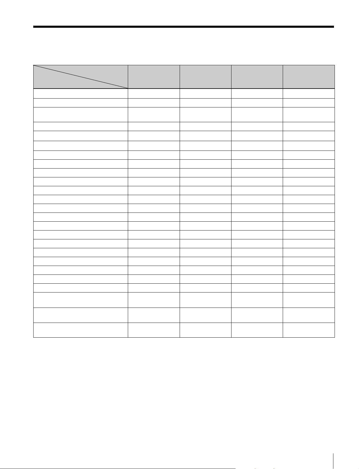
Available Monitors and Functions
For details on how to use each function, refer to the manual of your monitor.
Monitor BVM-A series BVM series
Available
function
Setup/adjustment with “Memory Stick”
CAPTURE
Function assignment to function
buttons
SCAN
H DELAY
V DELAY
MONO
APT
Aperture modification adjustment
COMB
CHAR OFF
COL TEMP
16:9
NATIVE SCAN
BLUE ONLY
R, G, B OFF
MARKER
Marker display mode setting
CHROMA UP
Menu operation
MONITOR I/O
Monitor selection
Display mode setting for the display
window
MANUAL adjustment buttons and
knobs
Picture adjustment presetting on
MANUAL adjustment knobs
a: available
– : not available
except BVM-A
–
– aa –
–
aaaa
aaa
aaa
aaaa
aaa –
aaaa
aaa –
aaa –
aaaa
aaaa
– aaa
aaaa
aaa –
aaaa
aaaa
aaa –
aaaa
aaaa
aaaa
aaa –
b)
a
aaaa
a)
a
b)
a
b)
a
a)
a
b)
a
b)
a
except PVM-L
–
–
c)
a
c)
a
b)
a
PVM-L series PVM series
a) Only compatible with monitors of the same series.
b) Some buttons and knobs may not function, depending on the input signal.
For details on limitations with each type of input signal, refer to the manual of your monitor.
c) H/V DELAY function is enabled when either the H DELAY or V DELAY button is pressed.
It is not possible to enable only H DELAY or V DELAY independently.
Available Monitors and Functions
5
Location and Function of Parts
For functions available with your monitor, see page 5.
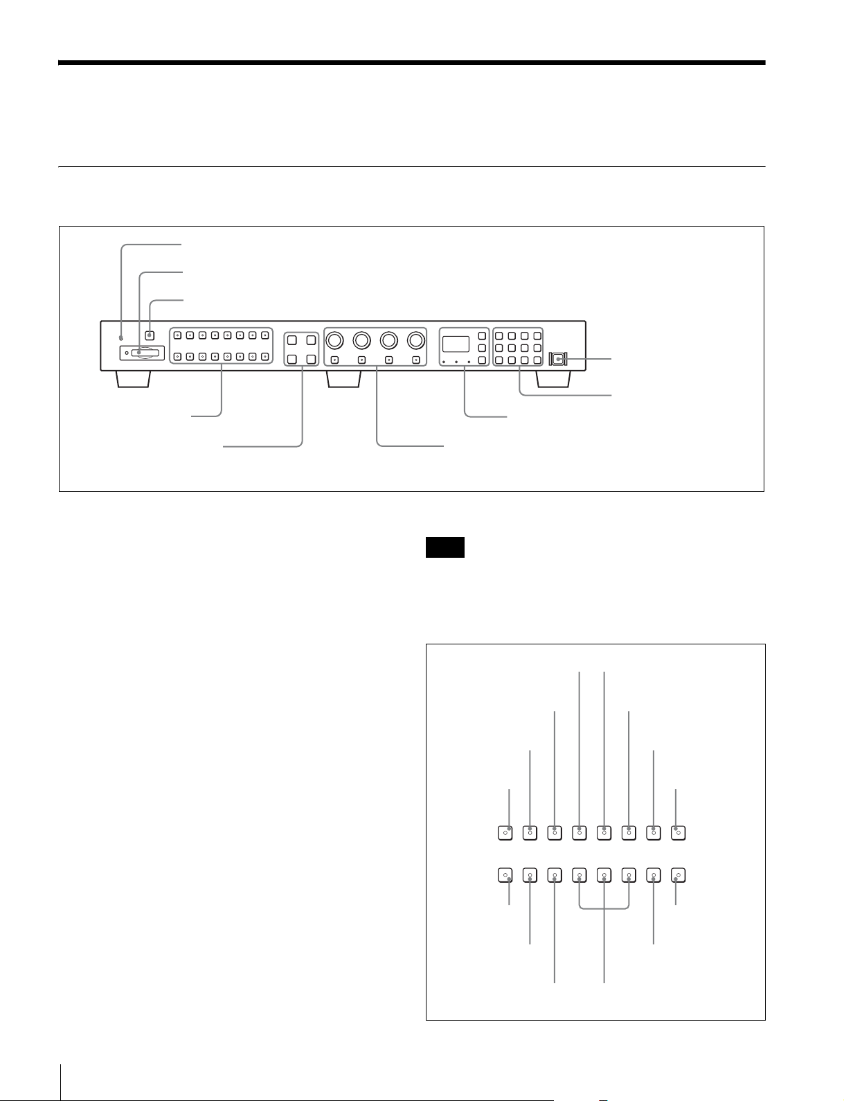
Front Panel
1 OPERATE lamp
2 Memory Stick insertion slot
3 CAPTURE button
4 Function buttons
6 MONITOR I/1 switch
7 Numeric keypad
8 Monitor selection buttons and lamps
5 Menu operation buttons
a OPERATE lamp
The lamp lights when the unit is turned on.
b Memory Stick insertion slot
The standard and duo type “Memory Stick” is available.
Insert the “Memory Stick” (optional).
When you use a “Memory Stick Micro”, do so after
attaching the M2 adaptor (optional).
For inserting/ejecting the “Memory Stick”, see page 10.
The setting and adjustment data saved in the “Memory
Stick” are only compatible with monitors of the same
series.
It is not possible to load the data stored in the “Memory
Stick” inserted in this slot to a monitor that does not
support the “Memory Stick,” or save the setting/adjustment
data in the “Memory Stick” inserted in this slot to such a
monitor.
c CAPTURE button
Press to capture the 3G/HD-SDI input signal as the still
picture in frame.
9 MANUAL adjustment buttons and knobs
You can assign other functions to the F1 to F16 buttons.
Note
The button may not function due to the input signal. For
the limitations with each type of signal, refer to the manual
of your monitor.
Factory preset setting
MONO button
V DELAY button
H DELAY button
SCAN button
SCAN
F1
16 : 9
F9
H DELAY V DELAY
F2 F3 F8
NATIVE
BLUE
SCAN
ONLY
F10 F11 F16
APT button
COMB button
CHAR OFF button
CHAR
MONO
APT COMB
F4 F5 F6 F7
R OFF G OFF B OFF MARKER
F12 F13 F14 F15
OFF
COL TEMP button
COL
TEMP
CHROMA
UP
d Function buttons
Press to change the operation conditions for the monitor.
Each time the button is pressed, the LED on the button
turns on and turns off, and the operation conditions are
changed. (The LED may not turn on depending on the
function.)
Location and Function of Parts
6
16:9 button
NATIVE SCAN button
BLUE ONLY button
CHROMA UP
button
MARKER button
R, G, B OFF buttons
 Loading...